Tuning Interface to Improve Corrosion Resistance of Electroless Ni-P Coating on AZ31B Alloy

School of Materials Science and Engineering, Xi’an University of Technology, Xi’an 710048, China
*
Author to whom correspondence should be addressed.
Metals 2018, 8(5), 328; https://doi.org/10.3390/met8050328
Submission received: 28 March 2018
/
Revised: 18 April 2018
/
Accepted: 26 April 2018
/
Published: 8 May 2018
Abstract
:Interface is crucial to enable desirable service performances of coatings on substrates. In this paper, Ni-P coatings were prepared on AZ31B alloy by using electroless plating, with the coating/substrate interface being tuned to improve the corrosion resistance. The interface tuning involved a phosphate treatment prior to the electroless plating, which created a uniform surface of the Mg substrate and finally led to Ni-P plating coatings with enhanced density during the electroless plating. Electrochemical testing was performed to compare the corrosion properties between the Ni-P coatings with and without phosphate treatment. The experimental results evidently showed that the introduction of phosphate treatment, especially after an annealing treatment, greatly improved the corrosion resistance. The underlying mechanisms, revealed by microstructural examinations, were that the phosphate treatment reduced the substrate surface roughness and likely promoted a high and uniform nucleation intensity of the Ni-P coating. Corrosion processes of the unannealed and annealed Ni-P coatings with an interfacial phosphate layer were further clarified for comparison.
1. Introduction
Due to their unique properties such as low density, high specific strength, good thermal conductivity, castability, and relatively high stiffness [1,2,3], magnesium (Mg) alloys can be potentially used in automotive, aerospace, electronics, chemical, and other fields. However, practical applications of the Mg alloys are highly limited by their poor corrosion resistance [4,5].
A uniform coating prepared by surface treatment methods is usually adopted to modify physical and chemical properties of metal materials, in particular to enhance the corrosion resistance. Electroless nickel (EN) coating is one of the common surface treatment methods, which has been widely employed to produce corrosion-resistant Ni-based coatings [6,7,8,9,10,11]. The corrosion resistance depends highly on the quality of EN coatings. In nanocrystalline Ni-P coatings, for example, a good corrosion resistance was found to be always associated with a high density [12,13]. To prepare dense nanocrystalline Ni-P coatings, the key is to reach a high nucleation as well as a low growth rate in coating formation, which are sensitive to many factors, such as the bath composition, preparation conditions, and characteristics of substrate [1,14,15,16,17].
Experimental results have showed that the growth rate of electroless Ni-P plating was accelerated in acid baths, causing dense hard coatings to form. While keeping the bath composition and preparing conditions unchanged, the growth rate of the EN coating relied mainly on the characteristics of substrate [18,19,20,21]. In particular, the substrate surface or interface between the coating and the substrate played a critical role in determine the coating quality. Previous reports demonstrated that a relatively rough substrate rather than a smooth one promoted a rapid formation of the Ni-P coating [22,23]. However, the Ni-P coatings derived from rapid formation usually contain cauliflower-like granules in large sizes, which are apt to yield high porosity and hence reduce the corrosion resistance.
The effect of substrate surface roughness on Ni-P coatings in alkaline baths has been extensively studied for steel substrates and Mg substrates [12,13,19,20,21]. In the case of Mg substrate, the corrosion resistance of Ni-P coatings is dominated by not only the coating quality but also the interfacial bonding, both depending on the Mg substrate surface condition. Although some studies have used a ground-polish with diamond paste to reduce the substrate surface roughness [23], the impact of surface roughness on the microstructure, interfacial bonding, and final electrochemical performance of the Ni-P coatings produced in the acid bath has not been systematically analyzed and discussed. In this paper, a phosphate treatment will be applied to create a phosphate layer on Mg substrate before Ni-P electroless plating. The influence of the phosphate layer on microstructure and interfacial bonding of the subsequent Ni-P coating will be investigated deeply. The electrochemical properties of the coatings with a tuned interface will be analyzed and discussed in comparison with those with no interfacial tuning.
2. Experimental Procedures
The substrate used in the present work is commercial AZ31B cast magnesium alloy. Rectangular coupons of the Mg alloy (10 × 15 × 3 mm3) were ground gradually from 1000 down to 3000 grit using silicon carbide papers, and were subsequently subjected to the pre-treatment process (Table 1).
The pre-treatment processes were as follows: (i) Alkaline cleaning was firstly performed to remove oils and greases from the coupons surface; (ii) Secondly, a phosphate treatment was adopted to reduce the substrate surface roughness; (iii) Finally, fluoride activation was applied.
To minimize air exposure and reduce atmospheric oxidation, the samples were rinsed thoroughly with deionized water and as quickly as possible after each step during the pre-treatment processing. After pre-treatment, the specimens were immersed in the EN plating acid bath (Table 1) for 20 min at 80 °C.
The structure of the Ni-P coatings were characterized by using Siemens X-ray diffractometer 5000 (XRD) equipped with a Cu Kα X-ray source. The surface morphology of the specimens was examined by using FEI QUANTA 2000 scanning electron microscopy (SEM) together with EDS analyses to determine the chemical composition of the deposits. Surface roughness of the samples was examined and measured by using a OLYMPUS Laser Scanning Confocal Microscopy (LSCM) instrument. At least five measurements on each side of the coupons were recorded to obtain an average value. Corrosion resistance was characterized by using the electrochemical method. The electrochemical tests were carried out on a CHI604D electrochemical workstation by using a classical three-electrode cell with platinum as the counter electrode. Saturated Ag/AgCl was used as the reference electrode, and the coating samples with 1 cm2 exposed area as the working electrode. All samples for electrochemical test were left standing for 600 s prior to the test in order to obtain stable open circuit potential (OCP). Potentiodynamic polarization was measured at a scan rate of 2 mVs−1 at room temperature in 3.5 wt % NaCl solution. The corrosion resistance was also measured under immersion in 3.5 wt % NaCl solution with pH 7 at room temperature. The sample surface was examined at regular intervals, in which the time for etch pits appearing can be recorded. After immersion testing, the surface morphology of samples was observed with SEM to understand the corrosion behavior.
The examination of adhesion was performed by using a WS-2005 single scratch tester. The critical load (LC) value was confirmed by the scratch tracks and acoustic emission signals, at which the coating exhibited adhesion failure or was removed from the substrate. The chronologies of the abrupt changes along the profile determined the critical loads on the scratch track. Acoustic emission signals were measured with a 200 μm tip radius cone-shaped diamond indenter under a loading rate of 50 N/min, loading range of 0–50 N, sliding speed of 10 mm/min, and scratch length of 10 mm.
3. Results and Discussions
3.1. Pre-Treatment Process and the Ni-P Electroless Plating Layer
The surface morphology and roughness of the AZ31B alloy substrate were greatly affected by the pre-treatment process. In this paper, two kinds of pre-treatment processes were adopted for comparison. One was alkaline cleaning followed directly by activation. The other was alkaline cleaning, phosphate treatment, and finally activation. The difference between the two pre-treatment processes is that one includes, while the other does not include, the phosphate treatment. Since the phosphate treatment created a phosphate layer on the Mg substrate, the two pre-treatment processes caused different substrate surfaces. After pre-treatment, the samples were subjected to electroless plating to produce Ni-P coatings. Two Ni-P coatings with different interfaces were accordingly obtained: one was Ni-P coating with interfacial phosphate layer (abbreviated NPC/Phosphate), and the other was Ni-P coating with no interfacial layer (abbreviated NPC).
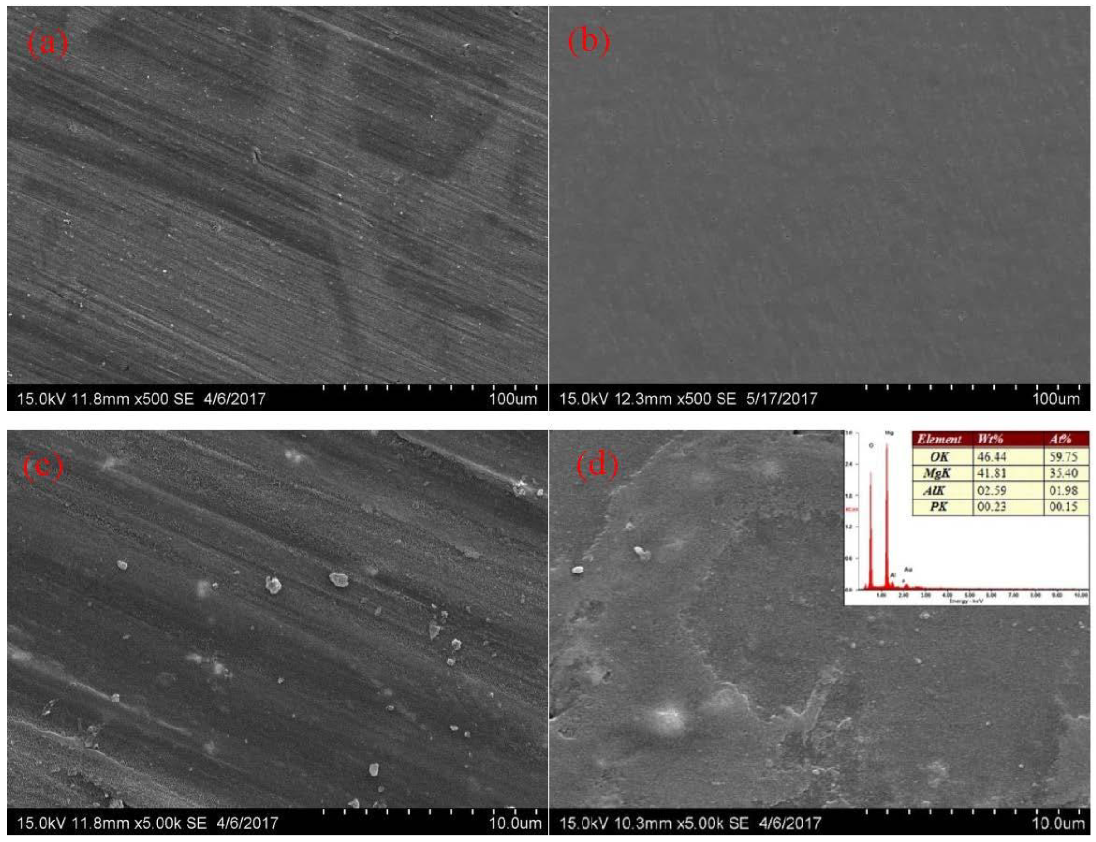
Figure 1 shows representative laser scanning confocal microscopy images to compare the sample surface morphology after every step during pre-treatment processing. The values of surface roughness (Ra) are accordingly given together with the images. It is quantitatively revealed that the final surface roughness of the substrate after pre-treatment processing was 0.71 ± 0.02 µm and 8.53 ± 0.22 µm, respectively, with and without phosphate treatment. The surface roughness was remarkably reduced after the phosphate process. Surface morphology of the substrates after phosphate treatment was further examined by using SEM, as typically shown in Figure 2. There were obvious scratches and pores on the surface of samples without phosphate treatment (Figure 2a,c). These surface defects were ready to serve as nucleation sites for the subsequent Ni-P coating formation. On the contrary, the surface of samples with phosphate treatment was uniform and smooth, free of scratches and pores (Figure 2b,d). The smooth and defect-free surface is favorable for the uniform formation of Ni-P coatings. EDX analysis was inserted in Figure 2d, it could be seen that the phosphate layer consist of Al, Mg, O, and P.
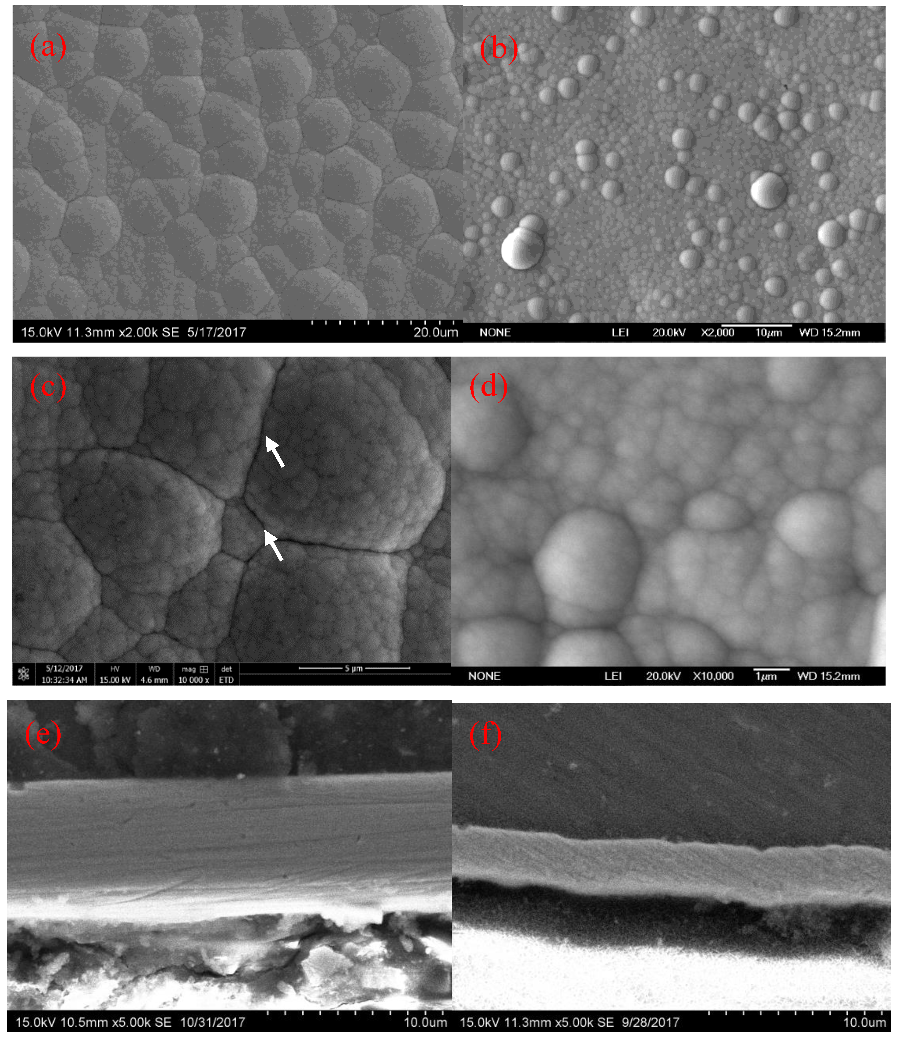
After pre-treatment, the Ni-P coatings were deposited on the Mg substrates by using the electroless plating. The relative technology parameters of the electroless plating are given in Table 1. Representative SEM images in Figure 3 show morphology of the Ni-P coatings derived from the two different pre-treatment processes, that is, NPC (Figure 3a,c) and NPC/Phosphate (Figure 3b,d), respectively. Cauliflower-like patterns are evident on both the two Ni-P coatings. However, the cauliflower-like domains in the two coatings are much different in size. The NPC has cauliflower-like domains (~1.0 to 20.0 µm) greater than those in the NPC/Phosphate (~0.5 to 2 µm). Additionally, there are clear cracks in the NPC as marked by white arrows in Figure 3c, while, in the NPC/Phosphate, no obvious cracks are detected.
Cross-sectional microstructure examinations demonstrate that the coating thickness of NPC and NPC/Phosphate are about 10 µm and 3 µm, respectively, as shown in Figure 3e,f. It is estimated that the plating rates were 30 µm/h and 9 µm/h, respectively, provided that the deposition time was both 20 min. The plating rate of Ni-P coating on the rough surface seems to be faster than on the smooth one. This is consistent with the previous report by Liu and Gao [2] that a greater deposition rate was achieved when a roughened AZ91 Mg substrate was used for electroless plating of Ni. Research by Meenan et al. [24] also pointed that the Pd growth depended strongly on surface roughness during the electroless deposition on tungsten oxide films, and smooth surfaces led to a uniform thickness. In present Ni-P coating on AZ31B alloy, it was similarly found that the slower deposition rate resulted in a uniform thickness. However, the adhesion between the coating and alloy substrate was weak, which was evaluated by the scratch test. The coating surface was drawn across by a diamond indenter as the applied load increased linearly from 0 to 50 N, with acoustic emission signals and frictional forces recorded accordingly. Experimental results showed that the critical load was about 28 N and 13 N for the NPC and NPC/Phosphate, respectively, which can be used to characterize the adhesion strength between the coating and the substrate [25]. It is estimated that the adhesion strength of the NPC was greater than that of the NPC/Phosphate. Ranjbar et al. [26], Zhao et al. [27], and Liu and Gao [28] also concluded that a substrate with a rougher surface improved the adhesion of the Ni-P film.
X-ray diffraction patterns of the NPC and NPC/Phosphate are presented in Figure 4, both displaying a broad diffraction peak at 44.8°. It is evident that the coatings have grains in nano-crystalline size. Available previous reports showed similar results and the broad diffraction pattern was interpreted as (1 1 1) plane of a face centered cubic phase of nickel with crystallite size of 1.2 nm [29,30]. Chemical composition of the coatings from EDX measurements demonstrated a phosphorus content of 3–4 wt % in both the two coatings. The phosphorus dissolved in the nickel lattice, disturbing the atomic arrangement, should be partially responsible for the formation of small grains (nano-crystalline) [23,31].
3.2. Corrosion Resistance of the NPC and NPC/Phosphate
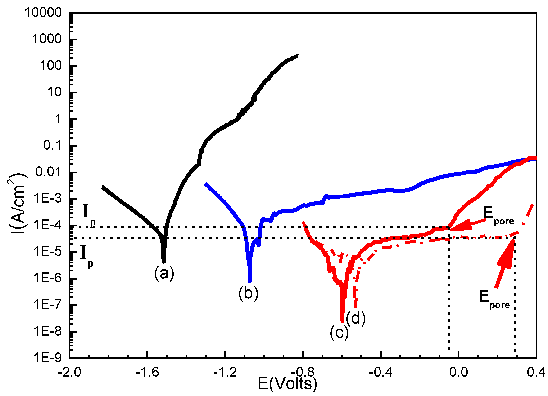
Potentiodynamic polarization curves of the AZ31B alloy, the NPC, and the NPC/Phosphate were shown in Figure 5 for comparison, which were measured in neutral 3.5 wt % NaCl solution. A significant shift in the corrosion potential () (Table 2) to a more positive value could be observed for the Ni-P coated samples by comparing with the bare substrate alloy, indicative of a good corrosion resistance resulting from the Ni-P coating. However, the corrosion current density () (Table 2) of the NPC coated alloy, extracted from the Tafel extrapolation on the potentiodynamic polarization curves(OCP ± 0.2 V vs. Sat. Ag-AgCl), was almost the same as the substrate alloy, which should be related to a high porosity in the coatings, caused by the high plating rate. The porosity could be determined on basis of the potentiodynamic polarization curves [32], following the equation below. The evaluations are listed in Table 2.
where P is the total coating porosity, is the polarization resistance of the substrate alloy, is the polarization resistance of the coated alloy, is the difference in corrosion potential between the coated alloy and the substrate, and is the anodic Tafel slope.
It is well known that Mg is one of the most electrochemically active metals. This means that the EN coatings should be cathodic to the substrate, and hence they can only serve as a physical barrier against corrosion. The remarkable potential difference between the substrate and the coated alloy will yield pore corrosion, once cracks and pores are presented. In other words, defect-free coatings are of special importance [33,34].
The corrosion current density () of the NPC/Phosphate is 1.26 × 10⁻⁶ A/cm2, obviously smaller than that of the NPC sample and bare Mg sample. In addition, it could be seen from the anodic branch that there was a current plateau at potentials E ~ −0.04 V vs. Sat. Ag-AgCl (, pore potential) for the NPC/Phosphate, showing a clear passivation behavior. Two distinct potential regimes are evident: within the first regime from the open circuit potential to ca. −0.04 V vs. Sat. Ag-AgCl, the current density raises very slowly and a current plateau is observed. The current density in the plateau part (at ca. −0.04 V vs. Sat. Ag-AgCl), , is about 8.75 × 10⁻⁵ A/cm2 in the 3.5 wt % NaCl solution. Within the second regime at potential E greater than −0.04 V vs. Sat. Ag-AgCl, the current increases rapidly with the applied potential. Samples preserve their shiny appearance up to −0.04 V vs. Sat. Ag-AgCl. This also means that the Ni-P coating on the alloy pre-treated with phosphate process exhibits corrosion resistance superior to that without phosphate process, as well as the bare Mg alloy.
As mentioned above, two main influencing factors dominate the corrosion resistance of the Mg alloy with Ni-P coatings. One is coating density, and the other is the interfacial bonding between the coating and the substrate. The denser the coating and the stronger the interfacial bonding, the higher the corrosion resistance is. In present Mg alloy with Ni-P coatings, the sample derived from phosphate treatment has an adhesion strength smaller than that without phosphate treatment, while the former displays corrosion resistance better than the latter. This implies that the effect of coating density on the corrosion resistance predominates over the effect of interfacial bonding in present Ni-P coating on Mg alloy. However, the corrosion resistance of NPC/Phosphate will be further improved if the interfacial bonding could be strengthened.
In order to increase the adhesion NPC/Phosphate, the samples were heated or annealed at 150 °C for 2 h to release the internal stress. The LC measured with scratch test was evaluated to be 30 N for the annealed NPC/Phosphate, which was much greater than its unannealed counterpart (13 N) and also slightly greater than the NPC sample. After tuning the interface, the corrosion resistance of the NPC/Phosphate samples was further improved. An immersion test at room temperature in 3.5 wt % NaCl solution was additionally used to characterize the corrosion resistance and the corrosion behavior of the unannealed and annealed NPC/Phosphate samples. The obvious appearance of etch pits were found after 6 and 28 days for the unannealed and annealed NPC/Phosphate samples, respectively.
Surface morphologies of the unannealed NPC/Phosphate after the immersion test are shown in Figure 6. The unannealed NPC/Phosphate showed a shiny appearance before immersion. With the time increases, some large cracks were found to form in the coatings (Figure 6a). Besides, the coating debonded from substrate, since the corrosion resulted in stress relief and interfacial delamination. Once the cracks formed, penetration of the corrosive electrolyte toward the Mg substrate grew rapidly and a strong galvanic response happened between the coating and the Mg substrate, leading to the formation of etch pits as illustrated in Figure 6b.
Evolution of surface morphologies of the annealed NPC/Phosphate during immersion test are shown in Figure 7. The Ni-P player was firstly passivated, see Figure 7a, and then the passivation layer was broken down and the corrosion of the Ni-P coating surface happened (Figure 7b), with a few black spots being visibly detected on the coating surface. Once the Ni-P coating was corroded and broken, galvanic corrosion was induced between the coating and the substrate, and the corrosion finally happened in the substrate (Figure 7c). Figure 7d representatively shows a deep etch pit observed in the annealed sample after 28 days immersion. The immersion test proved that the annealed NPC/Phosphate can effectively protect the Mg alloy from corrosion.
4. Conclusions
Electroless nickel plating was performed on AZ31B magnesium alloy, with different types of pre-treatment process for comparison: with and without a phosphate process. It was found that the phosphate process could effectively tune the interface by forming a phosphate layer on the substrate and hence remarkably reducing the surface roughness. In particular, after an annealing treatment, the coatings deposited on the substrate with the phosphate layer had a high density and a remarkably improved corrosion resistance. The underlying corrosion process of the Ni-P coating with interfacial tuning was different from those without phosphate treatment.
Author Contributions
Ruihong Wang designed the experiment, analyzed the mechanism and wrote the article, Beilei Ma collected the data. Ruihong Wang and Beilei Ma contributed equally to document retrieval, drawing charts and data analysis.
Acknowledgments
This work is financially supported by NSFC under No. 51771147.
Conflicts of Interest
The authors declare no conflicts of interest.
References
- Gu, C.; Lian, J.; Li, G.; Niu, L.; Jiang, Z. Electroless Ni-P plating on AZ91D magnesium alloy from a sulfate solution. J. Alloys Compd. 2005, 391, 104–109. [Google Scholar] [CrossRef]
- Liu, Z.; Gao, W. Electroless nickel plating on AZ91 Mg alloy substrate. Surf. Coat. Technol. 2006, 200, 5087–5093. [Google Scholar] [CrossRef]
- Guo, H.F.; An, M.Z. Growth of ceramic coatings on AZ91D magnesium alloys by micro-arc oxidation in aluminate-fluoride solutions and evaluation of corrosion resistance. Appl. Surf. Sci. 2005, 246, 229–238. [Google Scholar] [CrossRef]
- Hornberger, H.; Virtanen, S.; Boccaccini, A.R. Biomedical coatings on magnesium alloys—A review. Acta Biomater. 2012, 8, 2442–2455. [Google Scholar] [CrossRef] [PubMed]
- Hu, R.G.; Zhang, S.; Bu, J.F.; Lin, C.J.; Song, G.L. Recent progress in corrosion protection of magnesium alloys by organic coatings. Prog. Org. Coat. 2012, 73, 129–141. [Google Scholar] [CrossRef]
- Ranganatha, S.; Venkatesha, T.V.; Vathsala, K. Development of electroless Ni-Zn-P/nano-TiO2 composite coatings and their properties. Appl. Surf. Sci. 2010, 256, 7377–7383. [Google Scholar] [CrossRef]
- EI Mahallawy, N.; Bakkar, A.; Shoeib, M.; Palkowski, H.; Neubert, V. Electroless Ni-P coating of different magnesium alloys. Surf. Coat. Technol. 2008, 202, 5151–5157. [Google Scholar] [CrossRef]
- Seifzadeh, D.; Rajabalizadeh, Z. Environmentally-friendly method for electroless Ni-P plating on magnesium alloy. Surf. Coat. Technol. 2013, 218, 119–126. [Google Scholar] [CrossRef]
- Yuan, J.; Gao, Y.; Wang, J.H.; Hu, W.B. Preparation and corrosion resistance of Ni-P bilayer on magnesium alloy. Mater. Corros. 2017, 68, 1377–1388. [Google Scholar] [CrossRef]
- Winiarski, J.; Gałuszka, M.; Stankiewicz, A. Corrosion resistance of Ni-P\CePO4 coatings obtained from sol solutions. Mater. Corros. 2015, 66, 557–561. [Google Scholar] [CrossRef]
- Guo, S.Q.; Hou, L.F.; Guo, C.L.; Wei, Y.H. Characteristics and corrosion behavior of nickel-phosphorus coatings deposited by a simplified bath. Mater. Corros. 2017, 68, 468–475. [Google Scholar] [CrossRef]
- Vitry, V.; Kanta, A.-F.; Delaunois, F. Initiation and formation of electroless nickel-boron coatings on mild steel: Effect of substrate roughness. Mater. Sci. Eng. B 2010, 175, 266–273. [Google Scholar] [CrossRef]
- Yan, D.; Yu, G.; Hu, B.; Zhang, J.; Song, Z.; Zhang, X. An innovative procedure of electroless nickel plating in fluoride-free bath used for AZ91D magnesium alloy. J. Alloys Compd. 2015, 653, 271–278. [Google Scholar] [CrossRef]
- Gou, Y.N.; Huang, W.J.; Zeng, R.C.; Zhu, Y. Influence of pH values on electroless Ni-P-SiC plating on AZ91D magnesium alloy. Trans. Nonferrous Met. Soc. China 2010, 20, s674–s678. [Google Scholar] [CrossRef]
- Zuleta, A.A.; Correa, E.; Castaño, J.G.; Echeverría, F.; Baron-Wiecheć, A.; Skeldon, P.; Thompson, G.E. Study of the formation of alkaline electroless Ni-P coating on magnesium and AZ31B magnesium alloy. Surf. Coat. Technol. 2017, 321, 309–320. [Google Scholar] [CrossRef]
- Zhao, M.C.; Liu, M.; Song, G.L.; Atrens, A. Influence of pH and chloride ion concentration on the corrosion of Mg alloy ZE41. Corros. Sci. 2008, 50, 3168–3178. [Google Scholar] [CrossRef]
- Li, X.S.; Zhang, W.X.; Jiang, Z.H. Preparation and property evaluation of electroless Ni-P coatings on AZ91D magnesium alloy. Trans. Nonferrous Met. Soc. China 2007, 17, s835–s840. [Google Scholar]
- Dhinakaran, R.; Elansezhian, R.; Lalitha, A.A. Effect of nanoadditives with surfactant on the surface characteristics of electroless nickel coating on magnesium-based composites reinforced with MWCNT. Adv. Tribol. 2013, 2013, 1–10. [Google Scholar] [CrossRef]
- Sahoo, P. Optimization of electroless Ni-P coatings based on multiple roughness characteristics. Surf. Interface Anal. 2008, 40, 1552–1561. [Google Scholar] [CrossRef]
- Vitry, V.; Sens, A.; Kanta, A.F.; Delaunois, F. Experimental study on the formation and growth of electroless nickel-boron coatings from borohydride-reduced bath on mild steel. Appl. Surf. Sci. 2012, 263, 640–647. [Google Scholar] [CrossRef]
- Xavior, M.A.; Yarlagadda, P.K.D.V.; Gadhari, P.; Sahoo, P. Influence of process parameters on multiple roughness characteristics of Ni-P-TiO2 composite coatings. Procedia Eng. 2014, 97, 439–448. [Google Scholar]
- Krolikowski, A.; Butkiewicz, P. Anodic behavior of Ni P alloys studied by impedance spectroscopy. Electrochim. Acta 1993, 38, 1979–1983. [Google Scholar] [CrossRef]
- Crobu, M.; Scorciapino, A.; Elsener, B.; Rossi, A. The corrosion resistance of electroless deposited nano-crystalline Ni-P alloys. Electrochim. Acta 2008, 53, 3364–3370. [Google Scholar] [CrossRef]
- Meenan, B.J.; Brown, N.M.D.; Wilson, J.W. Characterisation of a PdCl2/SnCl2 electroless plating catalyst system adsorbed on barium titanate-based electroactive ceramics. Appl. Surf. Sci. 1994, 74, 221–233. [Google Scholar] [CrossRef]
- Stallard, J.; Poulat, S.; Teer, D.G. The study of the adhesion of a TiN coating on steel and titanium alloy substrates using a multi-mode scratch tester. Tribol. Int. 2006, 39, 159–166. [Google Scholar] [CrossRef]
- Ranjbar, M.; Garavand, N.T.; Mahdavi, S.M.; Irajizad, A. Electroless plating of palladium on WO3 films for gasochromic applications. Sol. Energy Mater. Sol. Cells 2010, 94, 201–206. [Google Scholar] [CrossRef]
- Zhao, H.; Huang, Z.; Cui, J. A new method for electroless Ni-P plating on AZ31 magnesium alloy. Surf. Coat. Technol. 2007, 202, 133–139. [Google Scholar] [CrossRef]
- Liu, Z.; Gao, W. The effect of substrate on the electroless nickel plating of Mg and Mg alloys. Surf. Coat. Technol. 2006, 200, 3553–3560. [Google Scholar] [CrossRef]
- Révész, Á.; Lendvai, J.; Loranth, J.; Padar, J.; Bakonyi, I.J. Nanocrystallization Studies of an Electroless Plated Ni-P Amorphous. Alloy. J. Electrochem. Soc. 2001, 148, C715–C720. [Google Scholar] [CrossRef]
- Totlani, M.K.; Athavale, S.N. Electroless Nickel for Corrosion Control in Chemical, Oil and Gas Industries. Corros. Rev. 2000, 18, 155–180. [Google Scholar] [CrossRef]
- Elsener, B.; Atzei, D.; Krolikowski, A.; Rossi Albertini, V.; Sadun, C.; Caminiti, R.; Rossi, A. From Chemical to Structural Order of Electrodeposited Ni22P Alloy: An XPS EDXD Study. Chem. Mater. 2004, 16, 4216–4225. [Google Scholar] [CrossRef]
- Chipatecua, Y.L.; Olaya, J.J.; Arias, D.F. Corrosion behaviour of CrN/Cr multilayers on stainless steel deposited by unbalanced magnetron sputtering. Vacuum 2012, 86, 1393–1401. [Google Scholar] [CrossRef]
- Song, Y.W.; Shan, D.Y.; Han, E.H. High corrosion resistance of electroless composite plating coatings on AZ91D magnesium alloys. Electrochim. Acta 2008, 53, 2135–2143. [Google Scholar] [CrossRef]
- Chen, X.M.; Li, G.Y.; Lian, J.S. Deposition of electroless Ni-P/Ni-W-P duplex coatings on AZ91D magnesium alloy. Trans. Nonferrous Met. Soc. China 2008, 18, s323–s328. [Google Scholar] [CrossRef]
Figure 1.
Representative Laser Scanning Confocal Microscopy images showing the sample surface after each pre-treatment step.
Figure 1.
Representative Laser Scanning Confocal Microscopy images showing the sample surface after each pre-treatment step.

Figure 2.
Representative SEM images showing surface morphologies of the AZ31B alloy pre-treated (a,c)without, and (b,d) with phosphate process. Note that (a,b) are in low magnification, while (c,d) in high magnification.
Figure 2.
Representative SEM images showing surface morphologies of the AZ31B alloy pre-treated (a,c)without, and (b,d) with phosphate process. Note that (a,b) are in low magnification, while (c,d) in high magnification.

Figure 3.
Representative SEM images showing the in-plane (a,c), and cross-sectional (e) morphology of the Ni-P coating with no interfacial layer (NPC); the in-plane (b,d), cross-sectional (f) morphology of the Ni-P coating with interfacial phosphate layer (NPC/Phosphate). Note that (a,b) are in low magnification, while (c,d) are in high magnification.

Figure 4.
XRD patterns of the NPC and NPC/Phosphate on AZ31B alloy.

Figure 5.
Polarization curves of (a) the bare Mg alloy substrate, (b) the NiPC, (c) unannealed and (d) annealed NPC/Phosphate, in a 3.5 wt % NaCl aqueous solution.
Figure 5.
Polarization curves of (a) the bare Mg alloy substrate, (b) the NiPC, (c) unannealed and (d) annealed NPC/Phosphate, in a 3.5 wt % NaCl aqueous solution.

Figure 6.
SEM images of unannealed NPC after immersion test showing (a) cracks, and (b) etch pits.

Figure 7.
Representative SEM images showing evolution in surface morphology of the annealed NPC/Phosphate during immersion test (a) passivation layer formation; (b) coating surface corrosion, (c) substrate corrosion, and (d) an etch pit.
Figure 7.
Representative SEM images showing evolution in surface morphology of the annealed NPC/Phosphate during immersion test (a) passivation layer formation; (b) coating surface corrosion, (c) substrate corrosion, and (d) an etch pit.


Table 1.
Bath Compositions and operating conditions of each process for Ni-P coating.
| Process | Compositions | Operating Conditions | |
|---|---|---|---|
| Temperature/°C | Time/min | ||
| Alkaline cleaning | Na3PO4•12H2O 20 g/L | 65 | 5 |
| NaOH 30 g/L | |||
| OP-10 3 mL/L | |||
| Phosphating | H3PO4 650 mL/L | 50 | 1 |
| C3H8O3 250 mL/L | |||
| C6H8O7 0.6 g/L | |||
| CuSO4•5H2O 0.4 g/L | |||
| Activation | HF (40%) 250 mL/L | 25 | 1 |
| Nickel plating | NiCO3·2Ni(OH)2•4H2O 12 g/L | 80 | 15 20 |
| NaH2PO2•H2O 20 g/L | |||
| C6H8O7 5 g/L | |||
| HF (40%) 12 mL/L | |||
| NH4HF 10 g/L | |||
| Thiourea 1 mg/L | |||
Table 2.
Results of potentiodynamic polarization curves of AZ31B substrate, different Ni-P coating in 3.5 wt % NaCl solution.
Table 2.
Results of potentiodynamic polarization curves of AZ31B substrate, different Ni-P coating in 3.5 wt % NaCl solution.
| Coating/Substrate | (×10−6 A/cm2) | (V vs. Sat. Ag-AgCl) | (V vs. Sat. Ag-AgCl) | (×10−5 A/cm2) | Porosity/% | /Ω | /V |
|---|---|---|---|---|---|---|---|
| AZ31B alloy substrate | 55.82 | −1.52 | - | - | - | 240.84 | 0.083 |
| Unannealed NPC | 19.80 | −1.08 | - | - | 6.78 × 10⁻³ | 354.96 | 0.12 |
| Unannealed NPC/Phosphate | 1.26 | −0.61 | −0.04 | 8.75 | 4.99 × 10⁻⁹ | 5282.61 | 0.027 |
| Annealed NPC/Phosphate | 2.06 | −0.53 | 0.29 | 2.03 | 4.76 × 10⁻²⁰ | 6231.70 | 0.046 |
© 2018 by the authors. Licensee MDPI, Basel, Switzerland. This article is an open access article distributed under the terms and conditions of the Creative Commons Attribution (CC BY) license (http://creativecommons.org/licenses/by/4.0/).
Share and Cite
MDPI and ACS Style
Ma, B.; Wang, R. Tuning Interface to Improve Corrosion Resistance of Electroless Ni-P Coating on AZ31B Alloy. Metals 2018, 8, 328. https://doi.org/10.3390/met8050328
AMA Style
Ma B, Wang R. Tuning Interface to Improve Corrosion Resistance of Electroless Ni-P Coating on AZ31B Alloy. Metals. 2018; 8(5):328. https://doi.org/10.3390/met8050328
Chicago/Turabian StyleMa, Beilei, and Ruihong Wang. 2018. "Tuning Interface to Improve Corrosion Resistance of Electroless Ni-P Coating on AZ31B Alloy" Metals 8, no. 5: 328. https://doi.org/10.3390/met8050328
Note that from the first issue of 2016, this journal uses article numbers instead of page numbers. See further details here.