Article

Microstructure, Mechanical Properties and Welding of Low Carbon, Medium Manganese TWIP/TRIP Steel

1
COMTES FHT a.s., Prumyslova 995, 334 41 Dobrany, Czech Republic
2
Department of Materials Science and Engineering, Ohio State University, Columbus, OH 43210, USA
3
New Technologies—Research Centre, University of West Bohemia, Univerzitni 8, 306 14 Plzen, Czech Republic
*
Author to whom correspondence should be addressed.
Metals 2018, 8(4), 263; https://doi.org/10.3390/met8040263
Submission received: 13 March 2018 / Revised: 4 April 2018 / Accepted: 9 April 2018 / Published: 12 April 2018
(This article belongs to the Special Issue Medium-Mn Steels, a Promising Type of the 3rd Generation Steels)

Abstract

:
Manganese twinning induced plasticity (TWIP) steels are attractive materials for the automotive industry thanks to their combination of strength and excellent toughness. This article deals with basic microstructural and mechanical properties of sheet metal of two heats of low-carbon medium-manganese steel with different aluminium levels. Microstructure observation was carried out using optical and scanning electron microscopy. Electron backscatter diffraction (EBSD) and X-ray diffraction were used for phase analysis. In an experiment that focused on the weldability of both materials, sheet metals were laser-welded using various laser power settings, with and without shielding gas. Various combinations of joints between materials of the two heats and sheet metal conditions were tested (work-hardened upon cold rolling + annealed). Mechanical properties of the weld joints were determined using miniature tensile testing and conventional hardness measurement. The strengths of miniature specimens of the weld metal were very close to the strength of the base material.

1. Introduction

Steels with Mn, Si, and Al in fairly high concentrations show high plasticity and strength when deformed thanks to the mechanical twinning (TWIP steels) or to martensitic transformation induced by deformation (TRansformation Induced Plastisity–TRIP steels) [1,2,3,4]. The outstanding and excellent properties of TWIP steels—superior formability and high energy-absorption, with high potential application in lightweight automobile, make this material the best candidate for automotive crashworthy constituents that require higher mechanical performance and also a good weldability [5,6].
An important factor determining the type of deformation mechanism in these types of steels is their stacking fault energy (SFE). The stacking fault energy (SFE) is defined as the difference in energy per unit fault area between faulted and perfect structures [7]. For SFE with values that are greater than 18 mJ/m2, the TWIP effect has a tendency to occur, for lower values, the TRIP effect is leading, with an α′  martensite phase being formed for SFE values that are below 12 mJ/m2. The SFE also depends strongly on the chemical composition and the experimental temperature of the tested steel. In steels with an Mn content (wt %) below 15%, the TRIP effect takes over, while for an Mn content that is higher than 25%, the TWIP effect is leading. It means that in an Mn content in the range 15–25%, both TRIP and TWIP effects coexist [4] and combine the final properties of both types of the above-mentioned steels (TRIP and TWIP). Mechanical properties of these steels are influenced by the formation of ε and α′  martensite during cooling and/or plastic deformation. It is documented that TRIP steels show better mechanical strength while the steels with TWIP effect reach better elongation to fracture [5]. Hence, the high ductility coexisting with the high level of strength can be acquired in developed TRIP/TWIP steels [8]. Another important factor for the existence of ε and α′-martensite is the carbon level. At lower carbon contents, martensite transformation occurs even in steels with high manganese content that is above 25%. Carbon can suppress martensitic transformation, but the particular volume of C that can be added is restricted due to the possible formation of M3C carbides [9]. To retain TWIP steels’ capacity to be welded to other standard non-manganese advanced high strength steels, it should be important to keep carbon level low.
Aluminium is a rather special alloying element in TWIP/TRIP steels. It plays an important role in suppressing hydrogen embrittlement. It is expected to reduce interior residual stress levels and increase the SFE. In addition, it should contribute to the formation of an oxide coating (alumina), which inhibits hydrogen absorption by the surface [10]. The role of the aluminium alloying has been also considered in this study in an austenitic cold rolled steel Fe–15.0Mn–0.1C–0.5 ÷ 1.5Al (wt %) in order to found the relation between microstructure evolution, occurrences of phase transformation, strain-hardening mechanisms, deformation behaviour, and mechanical properties.
Weldability of TWIP steels is crucial for their applications in the automotive industry. Several studies have focussed on the influence of welding conditions on the mechanical properties of weld joints of TWIP steels with dissimilar chemical compositions [11,12]. They found out that chemical inhomogeneities have a substantial effect on the presence or absence of second phases, such as ε martensite and α′ martensite. In summary, it can be specified that the welding of TWIP steels is not similar to either low-alloy or standard Cr-Ni austenitic steels due to substantial metallurgical dissimilarities [12].

2. Materials and Methods

The chemical compositions of steels in this experiment are given in Table 1. Basically, the only difference between both of the heats is the amount of aluminium (0.38% vs. 1.40%). Both heats were cast in a vacuum induction furnace into a round ingot mould. After casting, the ingots were hot forged at 1100 °C. These ingots were then forged into slabs with a cross-section of 280 × 130 mm. The slabs were then hot-rolled into strips to a final thickness of 8 mm. These strips were annealed at 850 °C for 2 h. After pickling, the annealed strips were cold-rolled with 2 inter-operation annealing to 1.2 mm of final thickness. Specimens of these strips upon 40% reduction were then annealed at 950 °C. The mechanical properties of these sheets were measured on standard tensile test samples, according to the EN ISO 6892-1.
The specimens were prepared by means of standard metallographic techniques of grinding and subsequent polishing. Their microstructures were revealed by two-stage etching: first with 10% Nital, and then with the Klemm’s II colour reagent [13]. Specimens for electron backscatter diffraction (EBSD) were electrolytically polished with a Struers Lectropol (Struers ApS, Ballerup, Denmark) machine and the A2 reagent at 35 V for approximately 20 s. The microstructures were documented using a Zeiss Axio Observer (Carl Zeiss Microscopy GmbH, Jena, Germany) optical microscope. EBSD analysis was performed and scanning electron micrographs taken by means of Jeol 7400F microscope and an HKL Nordlys EBSD camera from Oxford Instruments (Tubney Woods, UK).
Phase analysis by X-ray diffraction was carried out at room temperature using a Bruker D8 Discover diffractometer (Bruker AXS GmbH, Karlsruhe, Germany). The diffracted radiation was detected by means of a one-dimensional detector. A cobalt X-ray source has been used (λ = 0.1790307 nm). The instrument was equipped with a polycapillary lens that was focusing the primary X-ray beam into a circular spot with a diameter of 2 mm.
Laser welding of the experimental sheet metal was performed using the Trumpf TruDisk 5002 equipment (TRUMPF GmbH + Co. KG, Ditzingen, Germany) with the BEO D70 welding head. It is a diode-pumped Yb:YAG solid-state disk laser offering a maximum power of 5 kW. The laser radiation wavelength is 1030 nm. The laser beam is delivered to the work peace by the optical fibre of 200 μm in diameter.
The laser welding head was mounted on a Fanuc M 710iC/50 robot (FANUC, Oshino, Japan). Using an adjustment ring on the collimation optics, the laser beam can be defocused. By this means, the area of interaction between the laser and the workpiece material can be altered. The welding head also enables the shielding gas for welding to be supplied via plain as well as multi-nozzle. Accurate positioning of the working beam with respect to the workpiece is effected by a pilot spot and line lasers and with the aid of camera equipment. In this experiment, laser beam welding was used to make lap joints of sheets of two base metal compositions (heats T15-81 and T15-82) using three levels of laser power from 1350 to 1950 watts (see Table 2). Laser beam spot size had ~600 µm circle shape with Gaussian power distribution. The focus position was set to f0 mm on the sheet surface.
Various combinations of joints between the materials of the two heats and sheet metal (with a thickness of 1.2 mm each) conditions were tested (work-hardened upon cold rolling + annealed). Table 2 specifies the configuration of the weld joints.
Where shielding gas was used, its flow was set at 24 L/min. For all of the weld joints, the welding speed, Ws, was set at 20 mm/s. Shielding gases are required in many welding processes, and especially Laser welding. Shielding gases are used to provide an atmosphere that is conducive to welding—one without the presence of oxygen, hydrogen, or other elements that would cause weld defects. The amount of shielding gasses that are required are dependent on the welding process and the materials being welded. High energy welding processes, such as laser beam welding and electron beam welding, penetrate very deeply into a weld, and this causes a large area being fused, which means that there is more surface area for impurities to reach. Therefore, laser beam welding requires the use of sufficient amounts of high quality shielding gasses. Without shielding gas, welds show porosity and a high susceptibility to cracking. This cracking would be Hydrogen induced cracking (HIC), due to the obvious presence of hydrogen and oxygen in the atmosphere [14].
Heat input Q (1) as a characterization of the welding process is closely related to line energy LE which can be calculated using the Formula (2).
Q = LE × E
LE = (P × 60)/(WS × 1000)
where E is laser energy transfer efficiency, LE is line energy in kilojoules per millimetre, P is power in watts, and Ws is welding speed in mm/min. Line energy (LE) was calculated:
  • For 1350 W: 0.0675 kJ/mm
  • For 1650 W: 0.0825 kJ/mm
  • For 1950 W: 0.0975 kJ/mm
As the power is increased, line energy also increases; as is expected. But, even with the highest power and theoretical maximum efficiency (E = 1.0), the heat input (Q) of 0.0975 kJ/mm is an extremely low value. This data explains the very small heat affected zones consistent with the experiment. The configuration of the weld joints is shown in the figure below (Figure 1). Two sheets of the experimental material were overlapped and welded through the centre of the overlap area to ensure proper weld penetration.
Various combinations of joints between materials of the two heats and sheet metal conditions were tested (work-hardened upon cold rolling + annealed). Table 2 specifies the configuration of the weld joints. Where shielding gas was used, its flow was set at 24 L/min. For all of the weld joints, the welding speed Ws was set at 20 mm/s.
The properties of the welds were tested by means of standard Vickers hardness measurement across the weld section and by means of a miniature tensile test (MTT) on samples that were manufactured from the bottom sheet, top sheet, and the weld metal itself (see Figure 1). The method of testing by means of miniaturized tensile specimens has proved to be effective in earlier studies [15,16,17,18,19] and the values of mechanical properties are fully comparable with the results of standard tensile tests. A certain disadvantage of MTT tests is the frequent dispersion of the measured values. This is due to the small sample sizes and thus their increased sensitivity to various microstructural defects. On the other hand, this phenomenon may be beneficial since a subsequent analysis of sample microstructure and fracture areas focused on samples exhibiting reduced mechanical properties will help to detect the above-mentioned defects.

3. Results and Discussion

3.1. Microstructure Properties of Sheets in Initial States before Welding

The joints combined two sheet metal conditions for two heats. One condition was obtained by cold rolling and the other by annealing at 950 °C for 3 h. Both of the conditions were thoroughly documented in earlier work from the perspective of grain size and volume fraction of phases [20]. The differences between the heats consisted in the amounts of austenite, α′-martensite, and ε-martensite. Figure 2 presents the microstructures of both heats in both conditions: after cold rolling, and after annealing. It shows that the annealed material of the T15-81 heat contained less ε-martensite (etching with Klemm’s reagent shows ε-martensite colourless, it looks white in micrographs) than T15-82. This was confirmed by X-ray diffraction, whose results are given in Table 3. The colours of the other phases are as follows [13]: α′-martensite blue to dark brown, γ-austenite yellow to brown, EBSD analysis also confirmed the presence of all the above mentioned phases (see Figure 3).
The annealed microstructures of both the materials (T15-81 and T15-82) consisted of austenite and two martensite variants: α′ and ε. The amount of ε-martensite increased with aluminium content. This is inconsistent with the findings of Ryu et al. [10] who reported a beneficial reduction in the ε-martensite amount, owing to alloying with aluminium. This difference in behaviour may be related to the difference in the carbon content. Ryu et al. worked with materials containing 0.6% carbon, whereas the sheet metals in this study contained no more than 0.12% C. It appears that carbon interacts in a certain way with aluminium and contributes to reducing the proportion of ε-martensite. Cold rolling affects the microstructure with deformation-induced transformation processes. Cold rolling, which causes an increasing of the strain in the sheet induces twinning in γ (FCC—austenite), such twins further transform to ε (HCP—martensite) and ε transforms to α′ (BCC—martensite). The larger the introduced strain, the greater the amount of martensite.

3.2. Mechanical Properties of Sheets in Initial States before Welding

Mechanical properties of sheet metals prior to welding are reported in Table 4 and in the graphs in Figure 4. Engineering stress-strain curves (Figure 4) show a substantial increase in the elongation of the samples due to the annealing process.

3.3. Microstructure of the Welds

Macrographs of the weld joints are shown in Figure 5a,b. Figure 5a is a macrograph of weld joint 2, which was made of two annealed T15-82 sheets using the power of 1950 W. Clearly, higher power leads to full penetration in both of the sheets. Figure 5b is a macrograph of the weld joint between an annealed T15-82 sheet and a cold-rolled T15-82 sheet that was made using the power of 1650 W. Full penetration has not been achieved across the thicknesses of both the sheets, as documented here. The heat-affected zone is well visible in the bottom sheet T15-82c.
Due to the high energy density of solid-state laser welding, heat-affected zones are known to be very small and thin. The heat input due to laser welding is extremely low because of the narrow laser beam, which has a very defined area that effects the weld.
The weld zone of all the welds is made up of columnar grains that are typical of laser welding (see Figure 6). The weld can be observed as having a microstructure that is oriented down and away from the centre of the weld. This is consistent with the “keyhole” phenomenon that is associated with laser welding.
The microstructure of two weld metals welded with different power (1950 W and 1350 W) were analysed by means of EBSD. These were the sample 2 (1950 W) and sample 5 (1350 W). EBSD results show that the microstructure consists of α′-martensite—yellow, ε-martensite—red; γ-austenite—blue, so as the microstructure of the base metal. The distribution of these phases respects the microstructure decomposition of the phases that is caused by melting and subsequent solidification (see Figure 7). Also, the difference between these two welds in the phase composition is caused by the different cooling rate. The higher power 1950 W caused higher heat input into the welded specimen 2, thus the cooling rate in the weld metal was slower in comparison to the specimen 5 with lower heat input (1350 W). This difference in the cooling rate resulted in the higher amount of austenite (ca. 16%) in the coarser microstructure of specimens’ 2 weld metal, together with the lower amount of α′ (BCC) martensite (ca. 33%) in comparison to the higher amount of α′ martensite (43%) and lower content of austenite (ca. 10%) in the fine microstructure of the weld metal in the specimen 5. These variances caused the difference in the hardness performance of these welds with various welding powers (see Section 3.4). In general, α′ and ε-martensite content in the weld metal is higher in comparison with the base material of the annealed sheets, and hence the hardness of the welds is higher than the annealed base material.
The microstructure of the heat affected zones of the specimens of cold rolled steel shows slight grain growth, which would explain why the hardness was diminished in that area. However, the grains in the annealed sheets did not grow, therefore the hardness did not decrease in that region. Figure 8a–d shows the fusion border between the weld metal and the base material in both sheet conditions (i.e., cold-rolled and annealed) for T15-81 and T15-82.

3.4. Microhardness of the Welds

The hardness values of the specimens varied significantly based on the composition of the two sheets that were being welded. For specimens 1 through 6, the composition and laser power were varied. Compositions of T15-82 and T15-82 annealed were welded with laser power levels of 1950, 1650, and 1350 watts. Compositions of T15-82 annealed and T15-82 annealed were welded using the same power levels. Figure 8 demonstrates the effects of varying the welding power on post-weld hardness in weld joints T15-82a + T15-82c (Figure 9a) and T15-82a + T15-82a (Figure 9b).
As the graphs show, lower welding power results in a higher hardness of the weld metal. The most notable manifestation of this relationship can be seen in the joints of two identical annealed sheets T15-82 (Figure 9b). The explanation of this behaviour was discussed above in Section 3.3.
Another trend of weld metal hardness emerges from the comparison between joints that was made by gas-shielded welding (Ar) and by welding without shielding gas (Figure 10). In welds that were made by gas-shielded welding, the range and mean value of hardness at the weld centre were 257–365 HV1 and 322 HV1, respectively. In joints made without shielding gas, these parameters were 260–390 HV1 and 335 HV1, respectively. These values were only obtained from weld joints that were made with the welding power of 1650 W. It is possible to conclude that, in the case of welding with the same welding power of 1650 W, the higher hardness in the weld metal corresponds with higher hardness of base material. For example, the specimens 8, 11, and 12 with higher hardness of base material exhibit higher hardness in the weld metal in comparison to the specimen 7 with a lower hardness of both base metal and the weld.

3.5. Mechanical Properties according to Miniature Tensile Tests

The results of testing miniature tensile specimens positioned across the welds are listed in Table 5, including tensile strengths. The specimens exhibited generally good tensile strengths, over 1000 MPa—more than 80% of the base material in an annealed state; also, the yield strength was typically above 250 MPa. Welds made without shielding gas (welds 14–20) had a lower tensile strength than the ones of the same composition with shielding gas applied during welding. Without shielding gas, these welds performed significantly worse in many aspects than their shielded counterparts. This is most likely due to imperfections, impurities, and contamination from the air associated with welding without shielding. Also, the specimens that were made up of two annealed plates had a higher strain percentage. The plates made up of one cold rolled plate and one annealed plate varied in performance.
Selected specimens were examined by metallographic techniques in order to describe the location in which fracture occurred. The example in Figure 10 demonstrates that the fracture occurred in the weld. This holds for both cold-rolled and annealed sheets. In specimens with annealed sheets (Figure 11b) necking and elongation in the heat-affected zone is visible where ductility increased owing to heat effects on the material.
Engineering stress—elongation diagrams in Figure 12 show data for specimens that were chosen as representatives of various weld joint combinations. Where different sheet metal states were combined (annealed and non-annealed), the differences in strength and elongation are readily apparent.
Remarkable results were obtained from miniature tensile tests of specimens from the weld metal (Table 6). The main limiting factor of the weld metal was the value of elongation. This parameter was very low for welds 1–4, and therefore the YS (σ0.2) could not be evaluated.
However, the values of YS were very good for most of the specimens, and they usually exceeded the YS of both base material T15-81 and T15-82 in the annealed state. However, the variance of the measured values was large. The average tensile strength of argon-shielded welds was 954 ± 176 MPa. Non-shielded welds reached lower YS of 864 MPa, but a higher standard deviation of ±199 MPa. Fracture surfaces of the specimens, which had shown that very low ultimate and yield strength were examined. Figure 12 shows that the fracture surfaces of specimens with low YS and TS contained defects: porosity.
In most of the samples, intergranular brittle fracture dominated, combined with small areas of transgranular ductile fracture (Figure 13c,d). This behaviour explains the low values of elongation. There were observed numerous pores and non-metallic inclusions in the microstructure of the welds welded without the protection of shielding gas. The inclusions were mostly the complex Al/Mn/Si oxides and nitrides (Figure 14a,b).
Some samples exhibited good values of both YS and elongation. The best elongation was reached with specimen 13. The fracture area of this sample mostly shows the ductile failure (Figure 15a–c).

4. Conclusions

Using laser beam welding, both sheets in various treated conditions were joined successfully. Due to the process of annealing, the microhardness of welds in the annealed steel sheets is much lower than in the cold rolled steel. This produces a hardness curve of one sheet with lower hardness, increasing the hardness in the weld zone, and lower hardness again after the weld. The specimens that are comprised of cold rolled sheets exhibit similar curves with higher values of hardness in the base metal, then lower hardness in the weld zone, and then harder again in the base metal. In the weld zone, the microstructure plays a significant role in the hardness values. During the welding process, the microstructure homogenizes and the grains become refined to a size that is in between that of the cold rolled steel and the annealed steel. This would explain why the cold rolled hardness decreases in the weld zone, but increases in the annealed plate. Measurement has shown that higher hardness is obtained in welds with lower welding power. A similar trend can be identified by comparing joints that are made by gas-shielded welding and by welding without the protective atmosphere of argon. Welds that are made without shielding gas showed higher hardness.
Miniature specimens oriented perpendicularly to the weld axis exhibited relatively good yield strength and ultimate strength. Stress-strain diagrams indicate the relatively high elongation of the specimens. Poorer properties were found in the welds made without shielding gas. Although specimens that were oriented transversally fractured in the weld metal, specimens made entirely from the weld metal did not exhibit significantly poor mechanical properties, the lowest is the elongation that is given by the brittle fracture behaviour. Mean yield strength of the weld metal in joints made by gas-shielded welding exceeds the yield strength of both the annealed base metals (391 MPa on average). Their ultimate strength was approximately 950 MPa. Large variance of results for welds made without shielding gas is due to greater number of defects in the welds. The mean ultimate strength was above 850 MPa.

Acknowledgments

These results were created under the project entitled Development of West-Bohemian Centre of Materials and Metallurgy No.: LO1412, financed by the Ministry of Education, Youth and Sports of the Czech Republic.

Author Contributions

Pavel Podany and Martina Koukolikova designed the experiments and analysed the microstructure of base metal; Christopher Reardon analysed the microstructure of welds, measured hardness and evaluated the tensile tests; Radek Prochazka performed all mini-tensile tests; Ales Franc designed and performed the laser welding experiment. Pavel Podany wrote the paper.

Conflicts of Interest

The authors declare no conflict of interest.

References

  1. Kim, Y.G.; Kim, T.W.; Han, J.K.; Chang, R.W. Development of new austenitic Fe-Mn-Al-C steels for automotive applications. Key Eng. Mater. 1993, 84, 461–472. [Google Scholar] [CrossRef]
  2. Grässel, O.; Krüger, L.; Frommeyer, G.; Meyer, L.W. High strength Fe-Mn-(Al, Si) TRIP/TWIP steels development—Properties—Application. Int. J. Plast. 2000, 16, 1391–1409. [Google Scholar] [CrossRef]
  3. Frommeyer, G.; Brüx, U.; Neumann, P. Supra-ductile and high-strength manganese-TRIP/TWIP steels for high energy absorption purposes. ISIJ Int. 2003, 43, 438–446. [Google Scholar] [CrossRef]
  4. Escobar, D.P.; de Dafé, S.S.F.; Santos, D.B. Martensite reversion and texture formation in 17Mn-0.06C TRIP/TWIP steel after hot cold rolling and annealing. J. Mater. Res. Technol. 2015, 4, 162–170. [Google Scholar] [CrossRef]
  5. Saha, D.C.; Cho, Y.; Park, Y.D. Metallographic and fracture characteristics of resistance spot welded TWIP steels. Sci. Technol. Weld. Join. 2013, 18, 711–720. [Google Scholar] [CrossRef]
  6. Wang, T.; Zhang, M.; Xiong, W.; Liu, R.; Shi, W.; Li, L. Microstructure and tensile properties of the laser welded TWIP steel and the deformation behavior of the fusion zone. Mater. Des. 2015, 83, 103–111. [Google Scholar] [CrossRef]
  7. Bleck, W. Characterisation of High Mn Steels by New Numerical and Experimental Tools. In Proceedings of the 1st International Conference on High Manganese Steels: HMnS 2011, Seoul, Korea, 15–18 May 2011. [Google Scholar]
  8. Asghari, A.; Zarei-Hanzaki, A.; Eskandari, M. Temperature dependence of plastic deformation mechanisms in a modified transformation-twinning induced plasticity steel. Mater. Sci. Eng. A 2013, 579, 150–156. [Google Scholar] [CrossRef]
  9. Song, S.W.; Kwon, Y.J.; Lee, T.; Lee, C.S. Effect of Al addition on low-cycle fatigue properties of hydrogen charged high-Mn TWIP steels. Mater. Sci. Eng. A 2016, 667, 421–430. [Google Scholar] [CrossRef]
  10. Ryu, J.H.; Kim, S.K.; Lee, C.S.; Suh, D.-W.; Bhadeshia, H.K.D.H. Effect of aluminium on hydrogen-induced fracture behaviour in austenitic Fe-Mn-C steel. Proc. R. Soc. A 2012, 469. [Google Scholar] [CrossRef]
  11. Mujíca, L.; Weber, S.; Pinto, H.; Thomy, C.; Vollertsen, F. Microstructure and mechanical properties of laser-welded joints of TWIP and TRIP steels. Mater. Sci. Eng. A 2010, 527, 2071–2078. [Google Scholar] [CrossRef]
  12. Roncery, L.M.; Weber, S.; Theisen, W. Welding of twinning-induced plasticity steels. Scr. Mater. 2012, 66, 997–1001. [Google Scholar] [CrossRef]
  13. Vander Voort, G. Metallography: Principles and Practice; McGraw-Hill Book Co.: New York, NY, USA, 1999. [Google Scholar]
  14. Philips, D.H. Fundamentals and Principles of High Energy Density Welding. In Welding Engineering: An Introduction; Wiley: Hoboken, NJ, USA, 2016; Volume 1. [Google Scholar]
  15. Rund, M.; Procházka, R.; Konopík, P.; Džugan, J.; Folgar, H. Investigation of Sample-size Influence on Tensile Test Results at Different Strain Rates. Procedia Eng. 2015, 114, 410–415. [Google Scholar] [CrossRef]
  16. Konopik, P.; Dzugan, J.; Rund, M. Determination of Fracture Toughness in the Upper Shelf Region Using Small Sample Test Techniques. In Proceedings of the Metal 2015: 24th International Conference on Metallurgy and Materials, Brno, Czech Republic, 3–5 June 2015; pp. 710–715. [Google Scholar]
  17. Dzugan, J.; Konopik, P.; Rund, M.; Prochazka, R. Determination of Local Tensile and Fatigue Properties with the Use of Sub-Sized Specimens. In ASME 2015 Pressure Vessels and Piping Conference Volume 1A: Codes and Standards, Boston, MA, USA, 19–23 July 2015; ASME: New York, NY, USA; ISBN 978-0-79-185692-5.
  18. Dzugan, J.; Prochazka, R.; Konopik, P. Low Cycle Fatigue Tests with the Use of Miniaturized Test Specimens. In Proceedings of the Pressure Vessels and Piping (PVP-2017), Waikoloa, HI, USA, 16–20 July 2017. [Google Scholar]
  19. Podany, P.; Martinek, P. Thermomechanical processing of micro-alloyed steel. Mater. Tehnol. 2014, 48, 855–859. [Google Scholar]
  20. Podany, P.; Dlouhy, J.; Koukolikova, M.; Martinek, P.; Prochazka, R.; Kubina, T.; Duchek, M. Phase Composition of 15Mn-0.1C-0.4/1.4Al-Si TRIP/TWIP Steels after Cold Rolling and Annealing. In Proceedings of the 2016 7th International Conference on Mechanical and Aerospace Engineering (ICMAE), London, UK, 18–20 July 2016; pp. 121–126. [Google Scholar]
Figure 1. Weld configuration and sampling locations for mini-tensile specimens (C—cross, WM—weld metal).
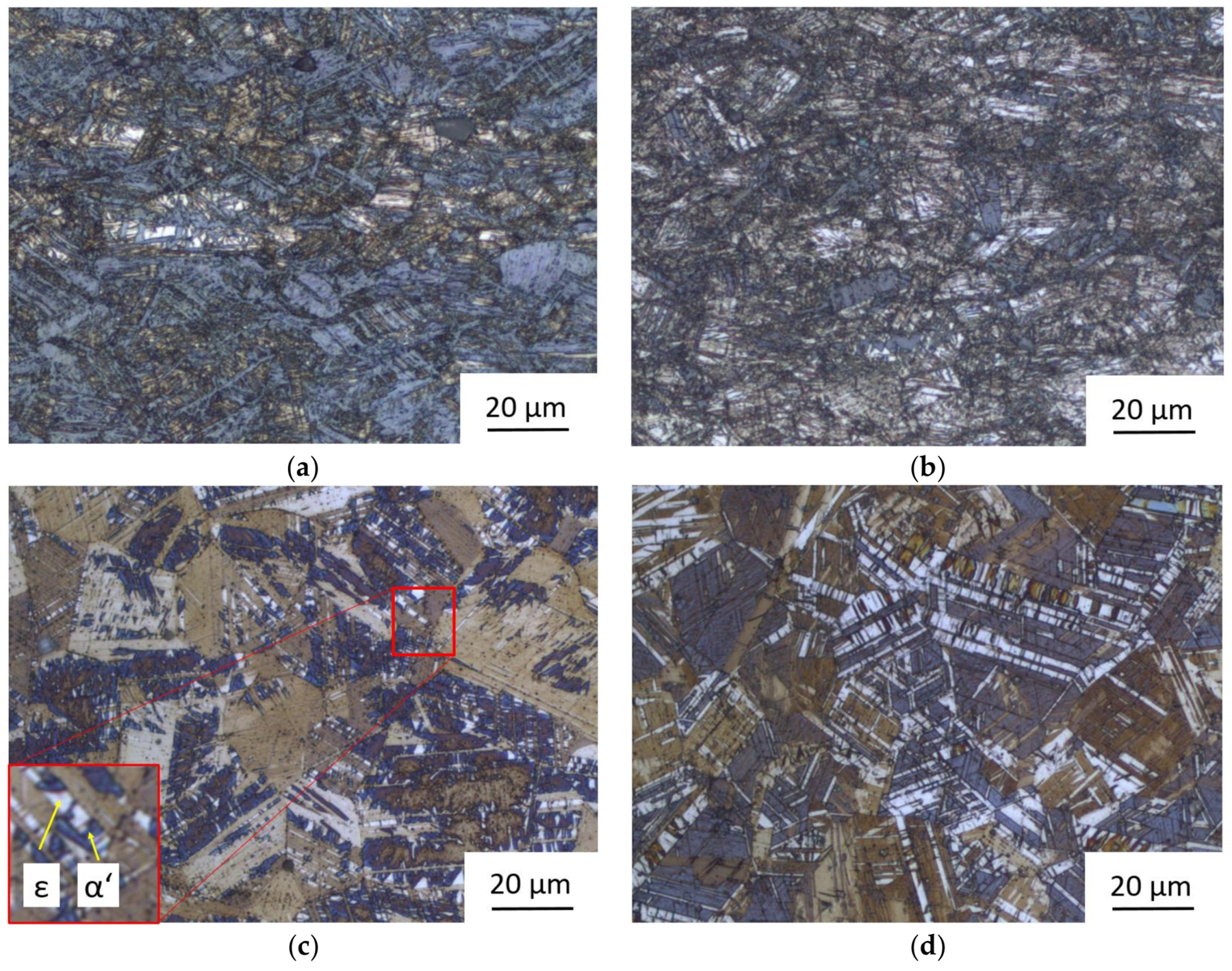
Metals 08 00263 g001
Figure 2. Microstructures of cold rolled and annealed state of both TWIP (Twinning induced plasticity) sheets: (a) Cold rolled sheet T15-81; (b) Cold rolled sheet T15-82; (c) Sheet T15-81 with the lower volume fraction of ε-martensite; and, (d) Sheet T15-82 with the higher volume fraction of ε-martensite.
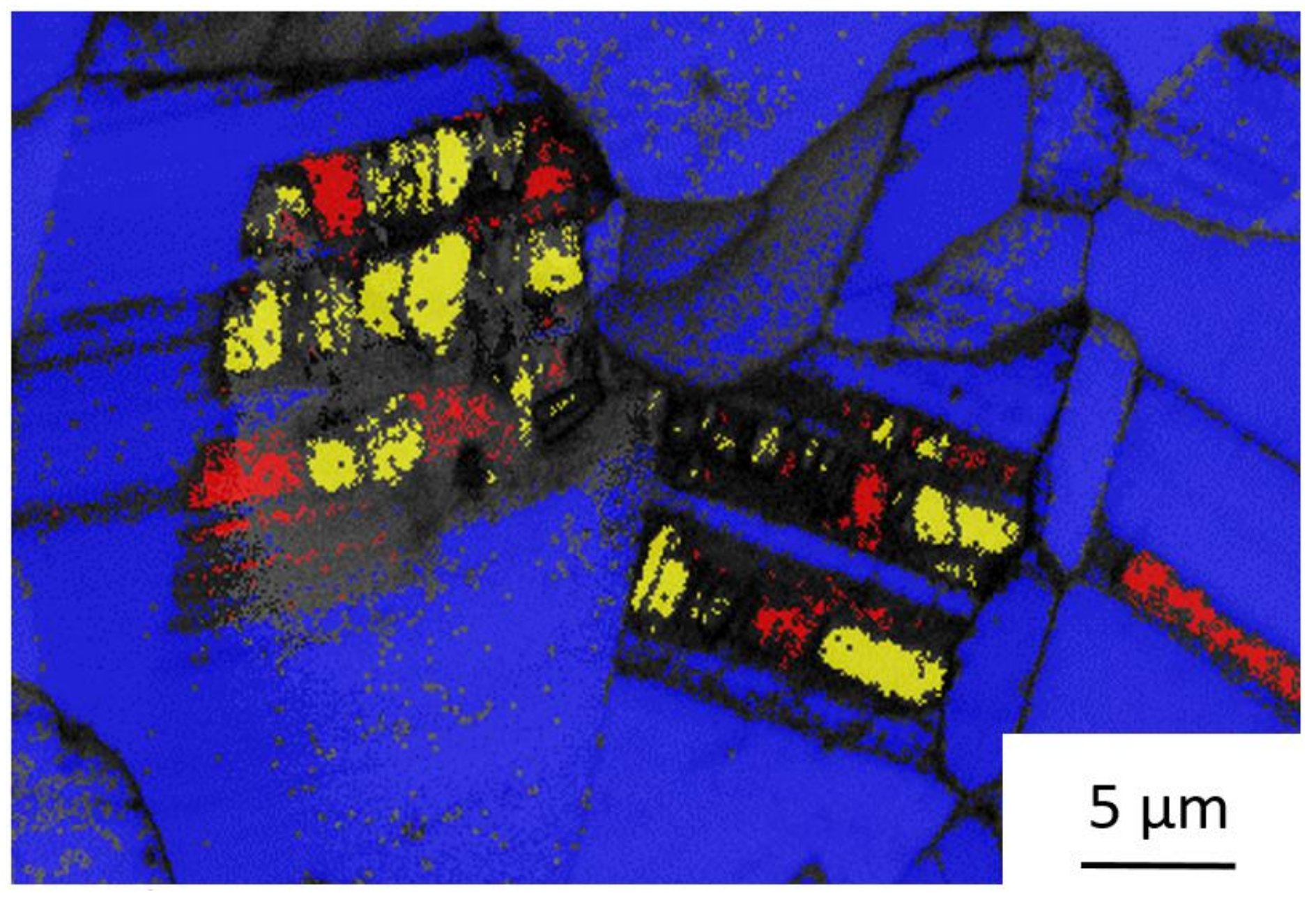
Metals 08 00263 g002
Figure 3. Electron backscatter diffraction (EBSD) analysis—identification of phases in annealed sheet T15-81: (α′-martensite—yellow, ε-martensite—red; γ-austenite—blue).
Metals 08 00263 g003
Figure 4. Engineering stress-strain curves of sheets in as cold rolled and annealed states: (a) T15-81; and, (b) T15-82.
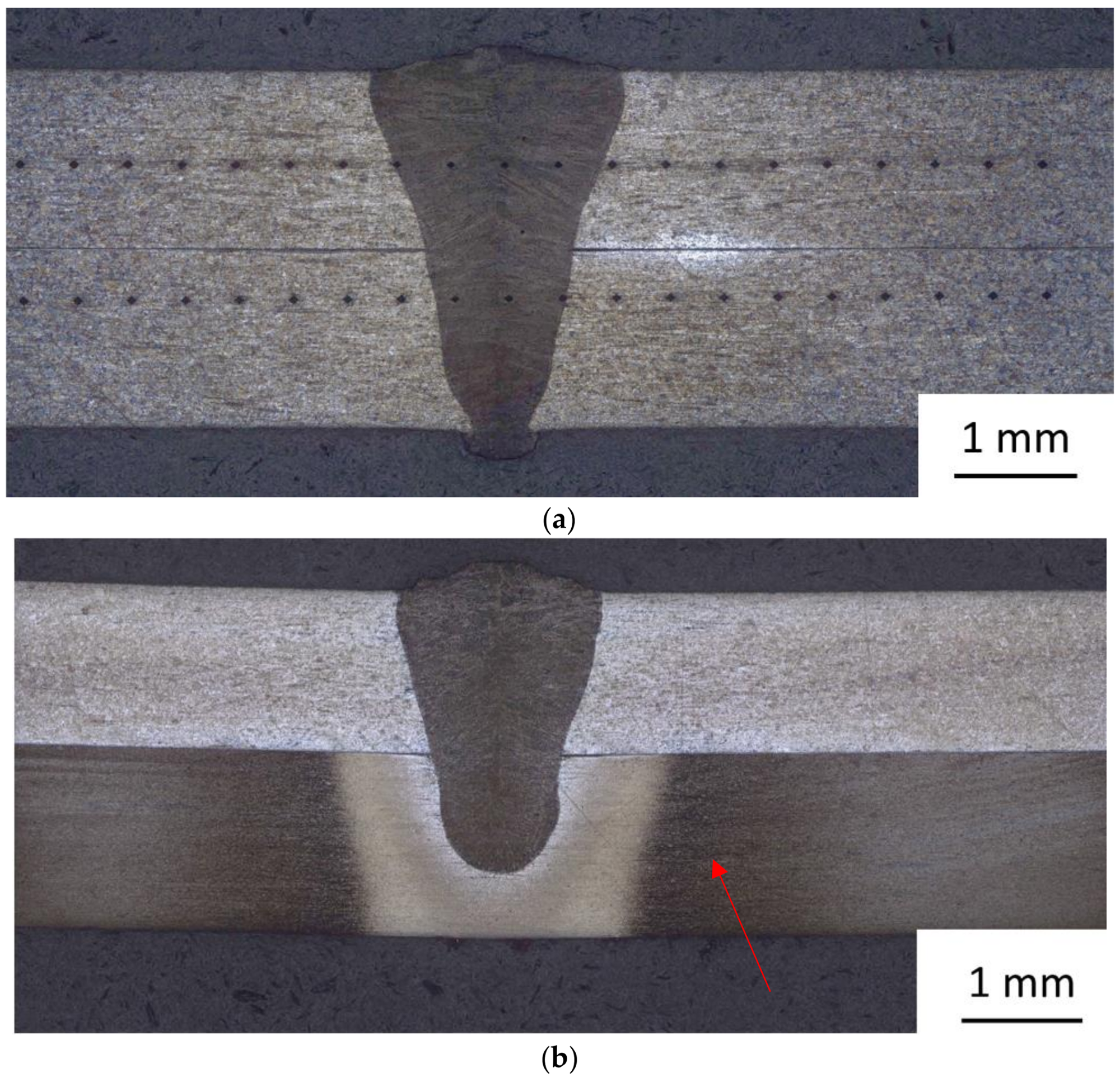
Metals 08 00263 g004
Figure 5. Macrostructure of welds with different combinations of sheets and laser power: (a) T15-82a + T15-82a welded with 1920 W; and, (b) T15-82a + T15-82c welded with 1650 W with heat affected zone marked with arrow.
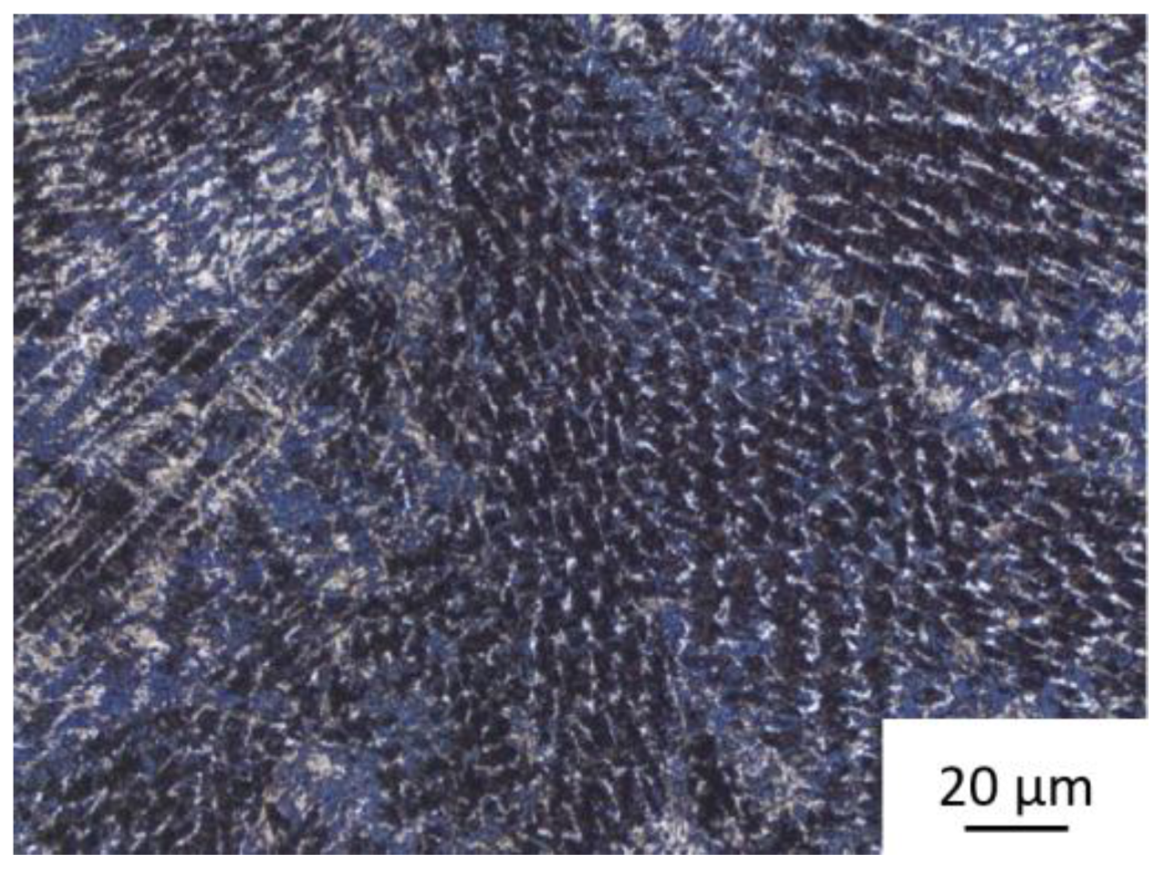
Metals 08 00263 g005
Figure 6. Typical microstructure of the weld metal.
Metals 08 00263 g006
Figure 7. The EBSD analyses (with same magnification for all figures) of weld metals welded with different powers: (a) analysed locality in the weld 2 (1950 W); (b) Phase map of the analysed locality in weld 2—α′-martensite—yellow, ε-martensite—red; γ-austenite—blue; (c) analysed locality in the weld 5 (1350 W); (d) Phase map of the analysed locality in weld 5—α′-martensite—yellow, ε-martensite—red; and, γ-austenite—blue.
Metals 08 00263 g007
Figure 8. The fusion border between the weld metal and the heat-affected zone in the welded sheets: (a) T15-81c (cold-rolled condition); (b) T15-81a (annealed condition); (c) T15-82c (cold-rolled condition); and, (d) T15-82a (annealed condition).
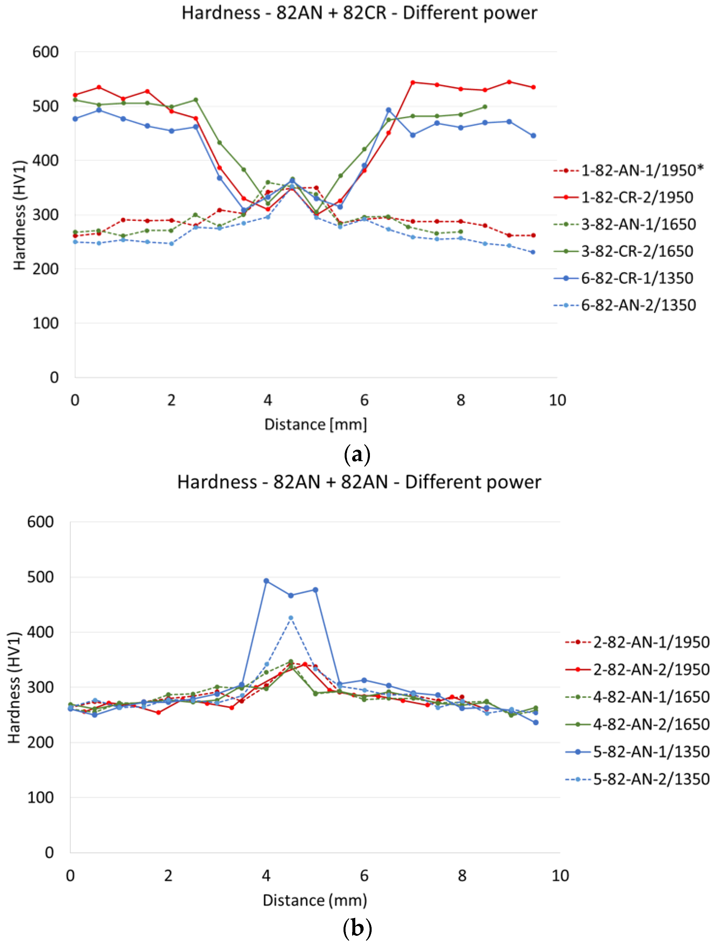
Metals 08 00263 g008
Figure 9. Hardness of weld joints made with various laser power levels: (a) T15-82a + T15-82c; (b) T15-82a + T15-82a (*1-82-AN-1/1950 means: Sample ID 1, sheet T15-82, annealed, 1—upper sheet, power 1950 W).
Metals 08 00263 g009
Figure 10. Hardness of weld joints vs. the use of shielding gas: (a) Joints made by gas-shielded welding; and, (b) Weld joints made without shielding gas.
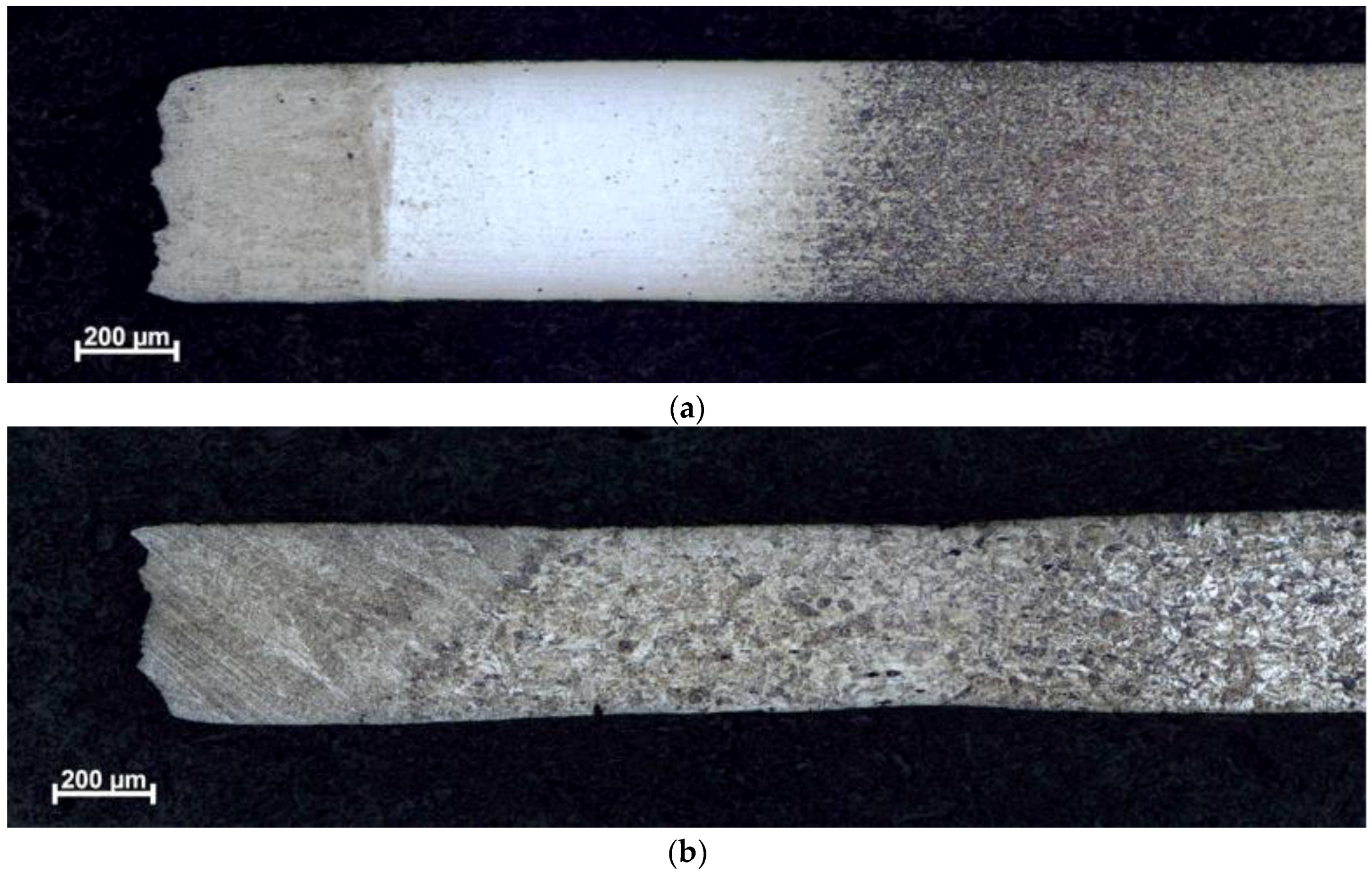
Metals 08 00263 g010
Figure 11. Microstructure on longitudinal sections through miniature tensile test specimens from weld 18 (the fracture is on the left): (a) Specimen of the top sheet T15-81c; and, (b) Specimen of the bottom sheet T15-82a.
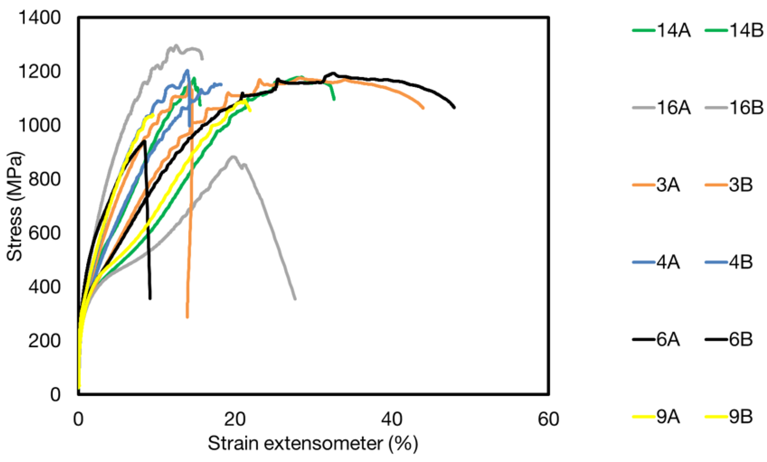
Metals 08 00263 g011
Figure 12. Engineering stress-strain diagrams of selected specimens: Ar shielded welds: weld 3—T15-82a + T15-82c (1650 W), weld 4—T15-82a + T15-82a (1650 W), weld 6—T15-82a + T15-82c (1650 W), weld 9—T15-81a + T15-82a; Not shielded welds: weld 14—T15-81a + T15-81a (1650 W), weld 16—T15-81a + T15-82a (1650 W), weld 19—T15-82a + T15-82c (1650 W).
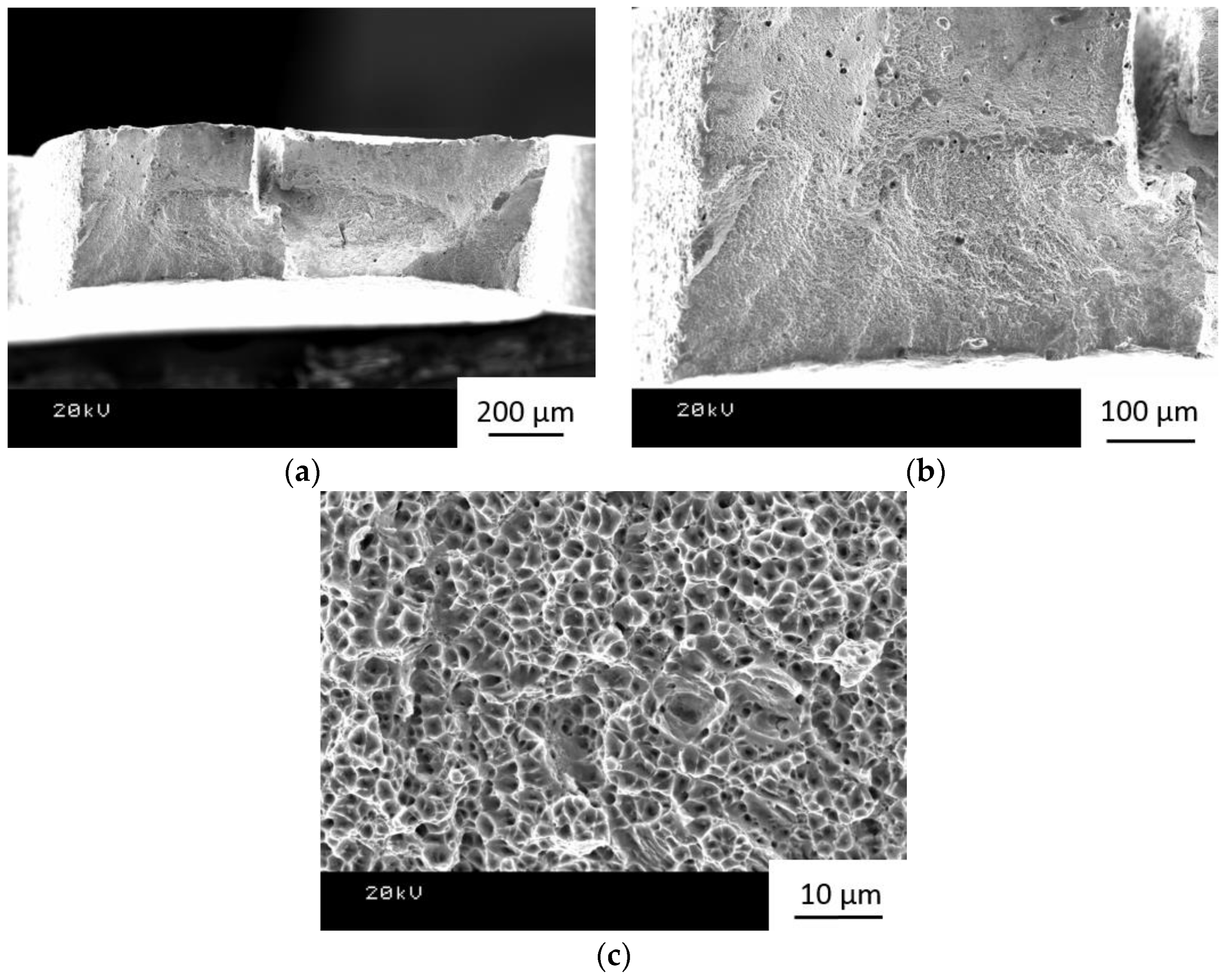
Metals 08 00263 g012
Figure 13. Fracture surface of 19_1 specimen: (a) View of the entire fracture surface; (b) Detail of the defect—pore in the corner of the fracture surface; (c) Predominantly intergranular fracture; and, (d) Detail of a ductile fracture region.
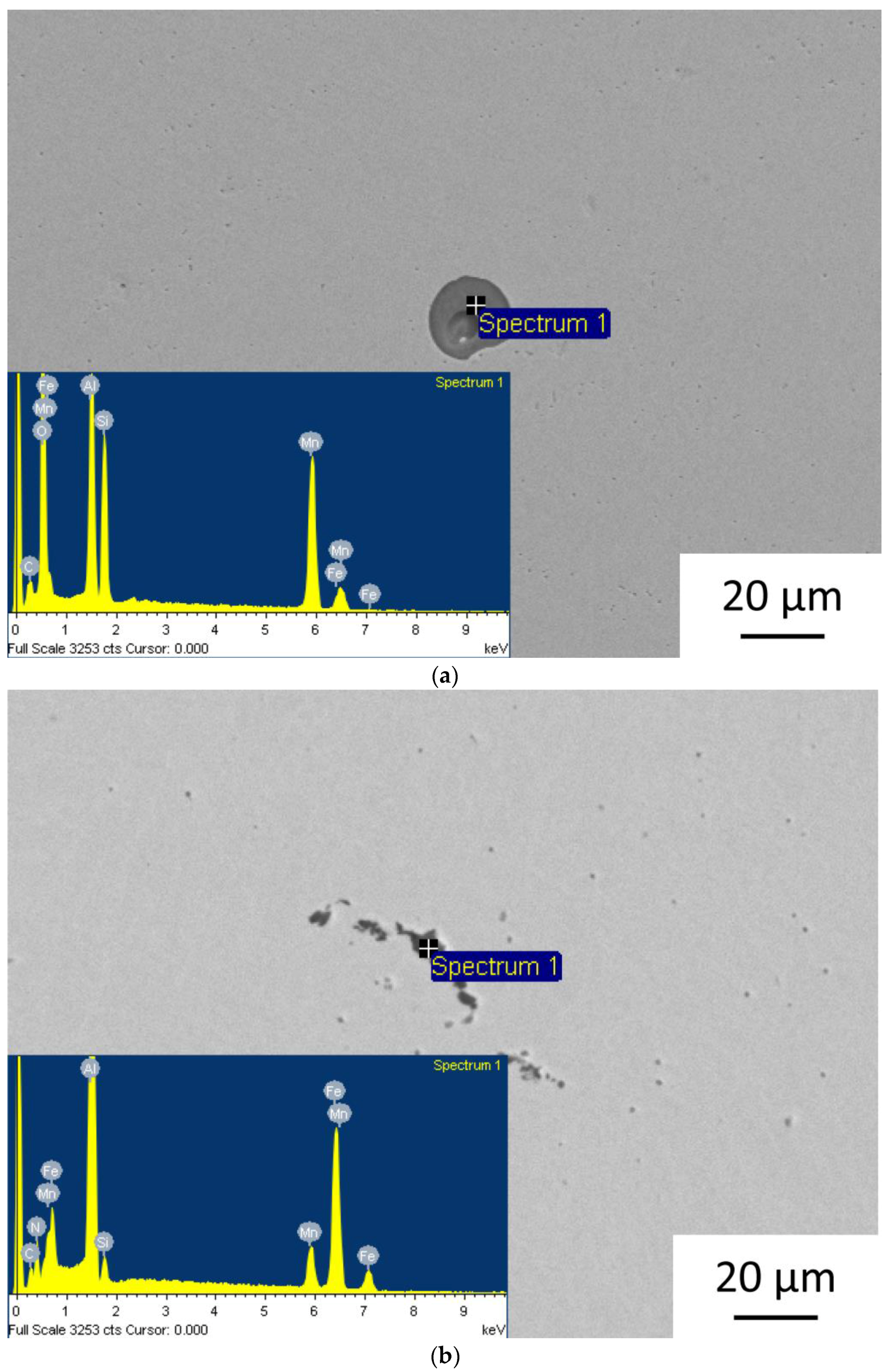
Metals 08 00263 g013
Figure 14. Inclusions in the microstructure of the weld of specimen 19: (a) Al/Mn/Si oxide; and, (b) AlMnSi nitride.
Metals 08 00263 g014
Figure 15. Fracture surface of 13_1 specimen: (a) View of the entire fracture surface; (b) Predominantly ductile fracture; and, (c) Ductile dimpled fracture region.
Metals 08 00263 g015
Table 1. The chemical composition of the experimental steel.
Heat No.Element (wt %)
MnSiAlCFe
T15/8115.11.580.400.12bal.
T15/8215.01.541.400.10bal.
Table 2. Laser welding parameters and configurations of welds of T15-81 and T15-82 sheet metals.
Sample IDPower (W)Shielding GasSheets Combination
11950ArT15-82a 1 + T15-82c 2
21950ArT15-82a + T15-82a
31650ArT15-82a + T15-82c
41650ArT15-82a + T15-82a
51350ArT15-82a + T15-82a
61350ArT15-82c + T15-82a
71650ArT15-81a + T15-81a
81650ArT15-82a + T15-82a
91650ArT15-81a + T15-82a
101650ArT15-81a + T15-82c
111650ArT15-82a + T15-81c
121650ArT15-82a + T15-82c
131650ArT15-81a + T15-81c
141650-T15-81a + T15-81a
151650-T15-82a + T15-82a
161650-T15-81a + T15-82a
171650-T15-81a + T15-82c
181650-T15-81c + T15-82a
191650-T15-82a + T15-82c
201650-T15-81a + T15-81c
1 a—annealed state of the sheet; 2 c—cold rolled state of the sheet.
Table 3. Volume fractions of phases determined by X-ray diffraction.
Sheetγ (FCC)α’ (BCC)ε (HCP)
T15-81-cold rolled10.072.018.0
T15-82-cold rolled11.062.027.0
T15-81-annealed37.932.529.6
T15-81-annealed43.18.548.4
Table 4. Mechanical properties of sheets T15-81 and T15-82 in cold rolled and annealed state.
SpecimenYS (MPa)TS (MPa)A5 (%)
T15-81-cold rolled147217427
T15-82-cold rolled126417187
T15-81-annealed257120038
T15-82-annealed300118434
Table 5. Mechanical properties of samples C (see Figure 1).
Weld SpecimenYS (MPa)TS (MPa)A5 (%)Weld SpecimenYS (MPa)TS (MPa)A5 (%)
1_A305.61272.133.011_A511.91184.717.0
1_B262.61270.515.511_B284.21224.832.0
2_A281.81235.534.212_A440.11029.420.0
2_B289.51195.516.012_B401.41256.119.0
3_A294.21174.444.013_A305.81170.122.0
3_B277.31158.214.013_B542.5946.76.7
4_A280.91203.714.014_A261.71143.415.5
4_B263.01154.118,214_B256.01177.532.5
5_A312.11149.938,815_A301.41271.320.0
5_B326.7992.48.115_B306.3936.99.5
6_A306.5940.09.116_A250.7870.827.5
6_B313.81192.647.616_B358.41295.416.0
7_A276.71207.021.217_A253.41257.018.5
7_B208.81176.933.317_B397.2904.26.4
8_A285.01021.18.918_A281.51202.816.3
8_B310.01215.89.518_B358.5595.53.0
9_A224.51081.82.019_A235.21054.610.0
9_B307.31038.96.519_B146.9290.72.3
10_A306.6913.010.020_A271.01120.021.0
10_B275.01207.917.520_B280.01148.020.4
Table 6. Mechanical properties of samples from weld metal—WM (see Figure 1).
Weld SpecimenYS (MPa)TS (MPa)A5 (%)Weld SpecimenYS (MPa)TS (MPa)A5 (%)
1_1-791.40.111_1397.01010.93.2
1_2-837.30.111_2388.9887.62.5
2_1-842.00.212_1342.8690.61.2
2_2-781.00.212_2364.71000.02.4
3_1-858.60.213_1374.51291.212.2
3_2-622.60.313_2309.71236.99.7
4_11046.41094.60.414_1278.71010.76.8
4_2-834.60.214_2262.21119.45.7
5_1401.0982.02.815_1658.8784.41.2
5_2379.1948.32.315_2618.5649.51.7
6_1370.1909.85.516_1428.1943.94.2
6_2414.71004.45.916_2432.8634.91.1
7_1279.41044.67.517_1366.8648.62.4
7_2284.11334.714.417_2395.21085.34.4
8_1374.3655.90.818_1401.3774.52.0
8_2349.0839.13.618_2372.8754.11.8
9_1376.31019.82.919_1420.2944.82.3
9_2369.5970.13.919_2404.5595.22.6
10_1315.41146.94.920_1293.6953.44.6
10_2307.71175.25.120_2282.81258.06.5

