1. Introduction
The die and mold industry plays a significant role in the manufacturing world [
1]. This is due to the fact that nearly all mass-produced parts are manufactured employing processes that include dies and molds, directly affecting not only the efficiency of the process, but also the quality of the product [
2]. Moreover, increasing demand in the automotive industry for high strength and lightweight components has led to the promotion and development of hot stamping (also known as Press Hardening) processes [
3]. Through this technique, a boron steel blank is heated until austenization at temperatures between 900 °C and 950 °C inside a furnace and then transferred to an internally cooled die set, where it is simultaneously stamped and quenched. The transformation of austenite into martensite occurs thanks to a rapid cooling of the blank, at a temperature range of 420–280 °C, along which the dies must be actively cooled at a minimum cooling rate of 27 °C·s
−1 [
4]. The temperature of the hot stamping tool must be kept below 200 °C in order to ensure the cooling of the blank, achieve high strength and prolong the lifespan of the tools [
5]. Thus, if the cooling ducts are not adequately designed, the temperature of the tool can be increased during the productive process, the quenching may not be successfully achieved and therefore, the final product would not meet requirements. Moreover, the temperature of the die could be non-homogeneous, resulting in hot areas where the quenching could not be achieved.
The efficiency of the cooling channels determines the characteristics and cooling time of the final part. Some authors [
6] relate low cooling rates and thermally induced surface defects on the component to an inadequate cooling system. These consequences could be avoided by the optimization and new arrangement of the cooling ducts. However, the cooling conduits are conventionally manufactured by drilling, hence only straight channels can be generated and often attain a not uniform heat transfer. This may lead to longer cycle times, unequal cooling and warp [
7]. Thus, the employment of traditional techniques for the manufacture of the inner cooling conducts of the stamping tools leads to restrictions on the final geometry of the parts.
Additive manufacturing technologies such as LMD have been developed within recent years, enabling the manufacture of high quality and fully dense metal parts. Reducing porosity is one of the main objectives in order to achieve good quality and mechanical properties in additively manufactured components. Some authors [
8,
9] perform meticulous studies in order to determine the effect of main process parameters on the metallurgy of the parts. Additive Manufacturing offer a real solution when manufacturing conformal cooling channels with complex geometries and, therefore, advance towards rapid cooling [
10].
There are two kinds of techniques for manufacturing conformal cooling ducts in hot stamping molds or dies: the layer-laminated method and the powder metallurgy-based additive manufacturing, belonging powder bed and powder nozzle technologies to the latter [
11]. On the one hand, by layer-laminated manufacturing, single layers are cut, stacked and then joined together in order to generate a final part. This technique is used for the production of plain and geometrically simple parts. For instance, Hölker et al. [
12] studied the design of straight holes in layered extrusion dies by joining lamellas with holes and thus creating cooling channels. On the other hand, components are additively built up layer by layer by locally melting a metal powder bed or stream, implying freeform manufacturing with nearly no geometric restrictions. These methods are usually performed to generate high complexity geometries and, regarding LMD, it is frequently combined with machining, giving rise to the so-called hybrid manufacturing.
Huskic et al. [
13,
14] investigated the integration of conformal cooling channels into forging dies and hot stamping tools by using Selective Laser Melting (SLM). Results showed that the hybrid die could withstand the mechanical loads originated during forging. In addition, Ahn et al. [
15] manufactured injection molds with conformal cooling ducts by combining direct metal rapid tooling and machining. As a result, the designed molds highly reduced the cooling time and required energy when compared to the conventional molds, improving the product quality. Müller et al. [
16] manufactured hybrid hot stamping dies by machining and additively building up inserts with conformal cooling ducts. As a result, the additively manufactured channels cooled six times faster than the conventional drilled channels. With regard to powder nozzle-based additive technologies, Vollmer et al. [
17] studied the integration and manufacturing of additively built up cooling channels for the fabrication of hot stamping tools. For this purpose, several grooves were machined and afterwards closed by LMD and finished by milling. From the literature review, it is noted that some research has been carried out in the field of conformal cooling and additive manufacturing. However, the number of references focusing on the application and suitability of these technologies to hot stamping tools is very limited. Hence, there exists a gap in the generation of conformal channels by depositing hot work steels, such as AISI H13 on CR7V-L, and the analysis of the resultant thermal and mechanical characteristics.
The present work aims to investigate the design and manufacturing of additively built up conformal cooling ducts, fabricated by combining LMD with 5-axis milling. Experimental study of laser metal deposition of AISI H13 tool steel powder on CR7V-L tool steel specimens has been carried out for the fabrication of the adaptive cooling channels. The performance of the channels is analyzed and compared to traditional straight ducts by metallurgical, mechanical tests and thermal analysis. Finally, the suitability of this process to a 3D geometry of higher complexity is investigated.
2. Materials and Methods
All experiments described in this work are performed on a 5-axis (three linear and two rotatory) conventional milling center rebuilt as a laser processing machine, named Kondia Aktinos 500 (Kondia, Elgoibar, Spain), whose work piece size capacity is 700 × 360 × 380 mm
3. In addition, a high power Yb:YAG fiber laser source, Rofin FL010 (ROFIN-SINAR Laser GmbH, Bergkirchen, Germany), is used, with a maximum power output of 1 kW, emitting wavelength of 1070 nm and pulse frequency range up to 5 kHz. The laser beam is guided through an optical multi-mode fiber from the laser source to the processing machine, generating a circular laser spot of 2 mm on the surface of the work piece, situated at a 200 mm focal distance. The powder is fed by means of a Sulzer Metco Twin 10-C powder feeder (Oerlikon Metco, Pfäffikon, Switzerland) and an in-house designed coaxial nozzle, EHU/Coax 2015 (UPV/EHU, Bilbao, Spain) [
18], while argon is used as both drag and shielding gas.
Three different materials are used along the present investigation in order to generate the final part: CR7V-L, AISI H13 (1.2344) (Flame Spray Technologies, Duiven, The Netherlands) and AISI 316L (1.4404) (Erasteel, Commentry, France). On the one hand, CR7V-L hot work tool steel by Kind and Co. Edelstahlwerk, Wiehl, Germany [
19] is a special high Cr-alloyed steel commonly used in hot work applications, such as hot forming tools of structural automobile parts. Furthermore, it is characterized by excellent high temperature strength and wear resistance, as well as good thermal fatigue resistance. On the other hand, AISI H13 is a Cr-Mo-V alloyed tool steel with a high level of resistance to thermal shock and fatigue and good temperature strength. Thus, these properties make AISI H13 particularly valuable for tooling. The chemical composition and thermal properties of the studied materials are shown in
Table 1 and
Table 2, respectively.
Hence, CR7V-L slabs are used as substrate and AISI H13 metallic powder as filler material so that the conformal cooling channels are closed. Both materials are compatible hot work tool steels with similar thermal properties, such as thermal conductivity and coefficient of thermal expansion. Besides, AISI 316L austenitic stainless steel is used as intermediate layer in order to relax internal stress and improve the weldability of the materials. Otherwise, the direct deposition of AISI H13 with no intermediate layer results in the cracking of the part. The preference of choosing AISI 316L instead of other interface materials such as nickel alloys is due to its higher thermal conductivity and ease of LMD.
The present investigation is performed on a 100 × 120 × 32 mm
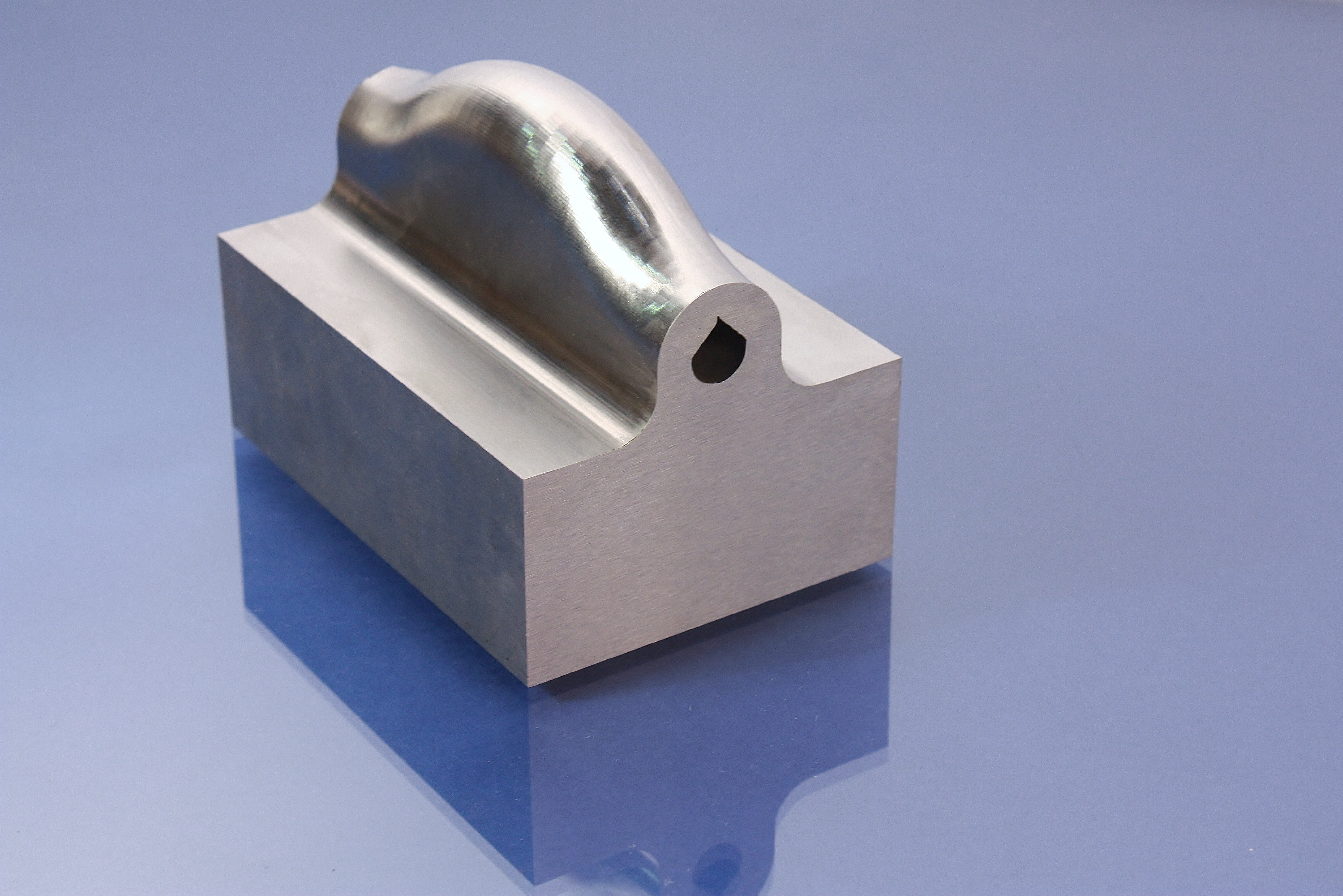
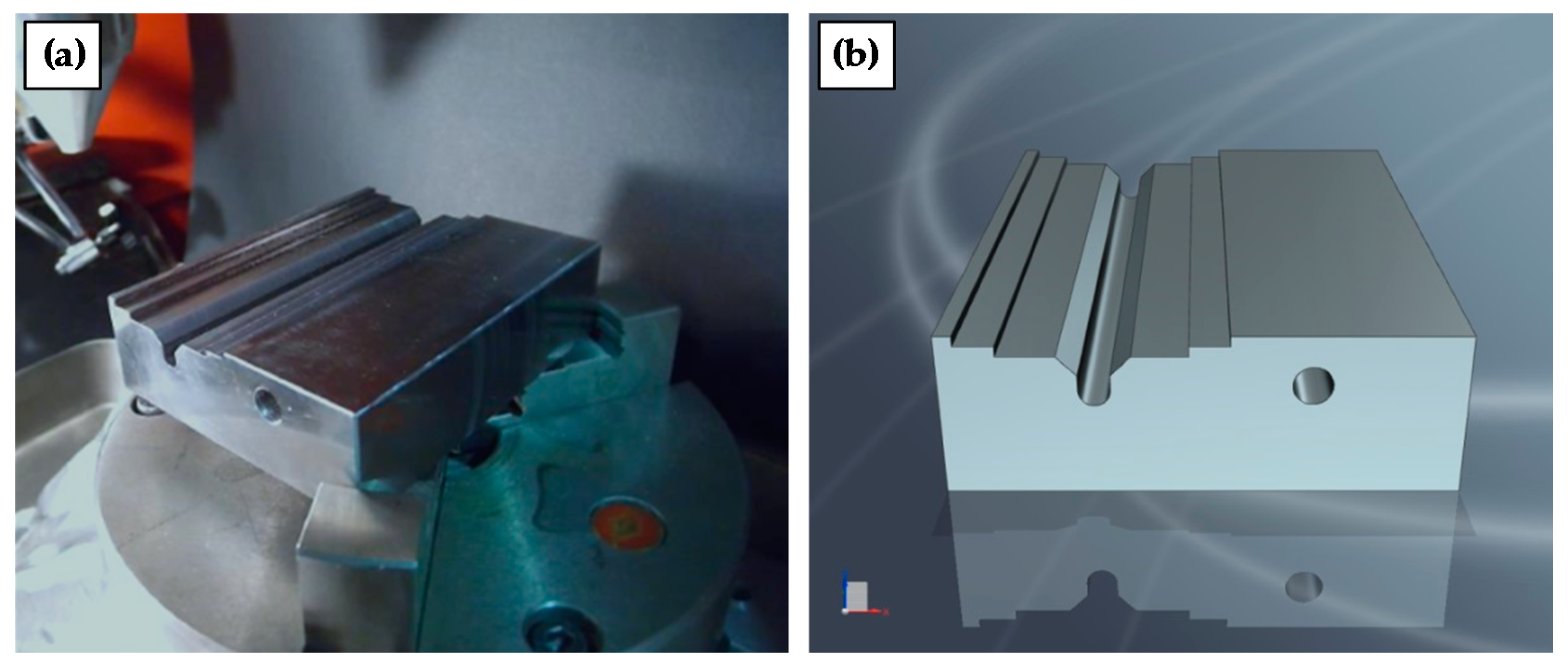
3 CR7V-L hot work steel slab, in which two different cooling channels of six millimeters of diameter at a depth of ten millimeters below the surface are generated: one is conventionally drilled and the other additively manufactured via LMD, see
Figure 1. At first, the CR7V-L substrate is soft annealed by holding the specimen at 840 °C for five hours with slow cooling in furnace (Helmut ROHDE GmbH, Prutting, Germany) in order to reduce its high hardness, 59.6 HRC, and allow its preparation by machining. This preparation consists of directly drilling a first duct and milling a 45° V-notch for the LMD operation. Once the preparatory phase is concluded, the part is ready to be submitted to the LMD process, whose aim is to close the milled V-notch so that an additively manufactured channel comparable to the drilled one is generated. Moreover, accessibility issues and geometric restrictions are considered for verifying the suitability of the available nozzle when manufacturing the part.
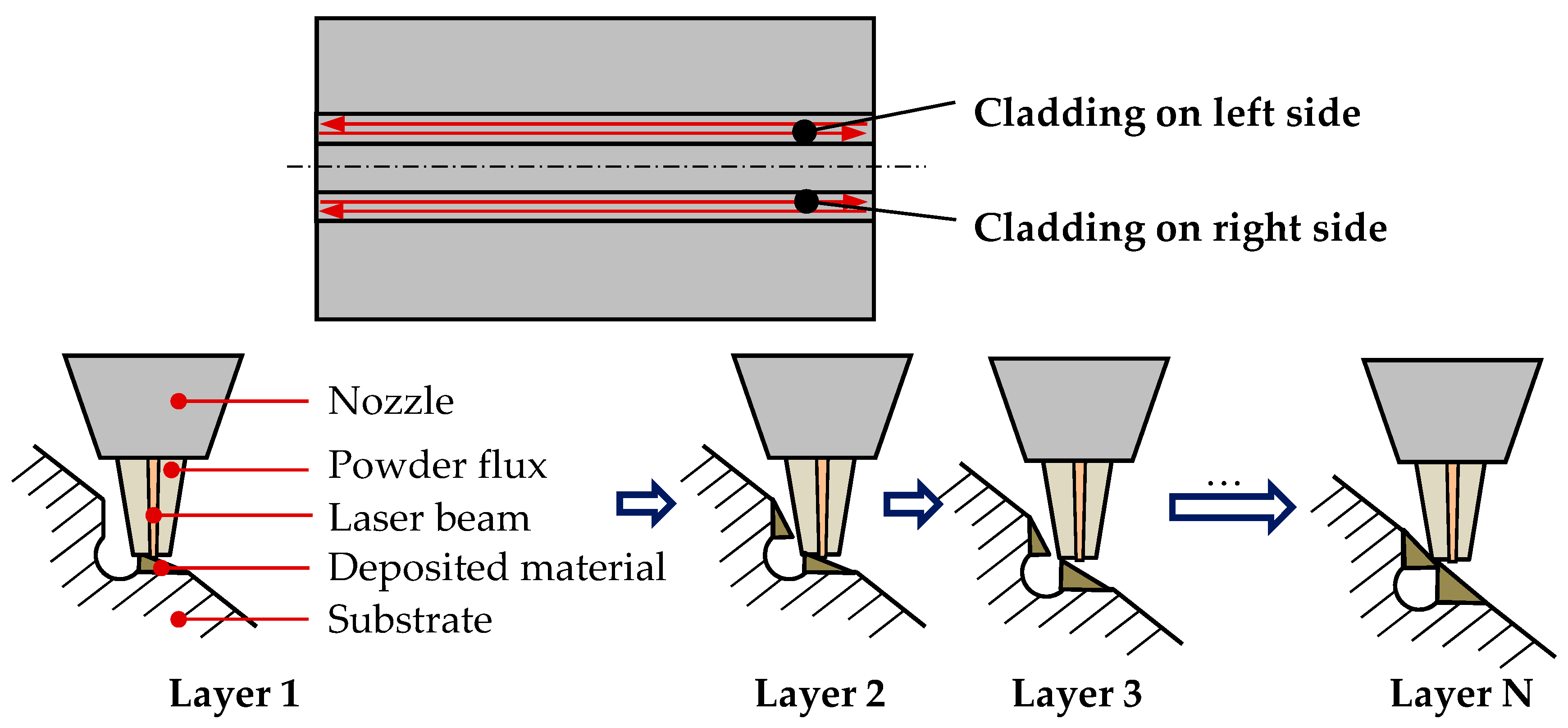
Along the LMD process, two different materials are deposited: AISI 316L stainless steel as intermediate layer and AISI H13 hot work steel for the surface coating. Different deposition strategies and process parameters are used for attaining sound clads with each material. Firstly, AISI 316L is used in order to seal the V-notch and hence generate the channel, while AISI H13 is added over it until the upper surface of the part is reached. For that purpose, the AISI 316L intermediate layer is deposited on the right and left slopes of the milled V-notch alternately, following a longitudinal zigzag cladding strategy in which the surface of the part and the nozzle are perpendicularly orientated as shown in
Figure 2.
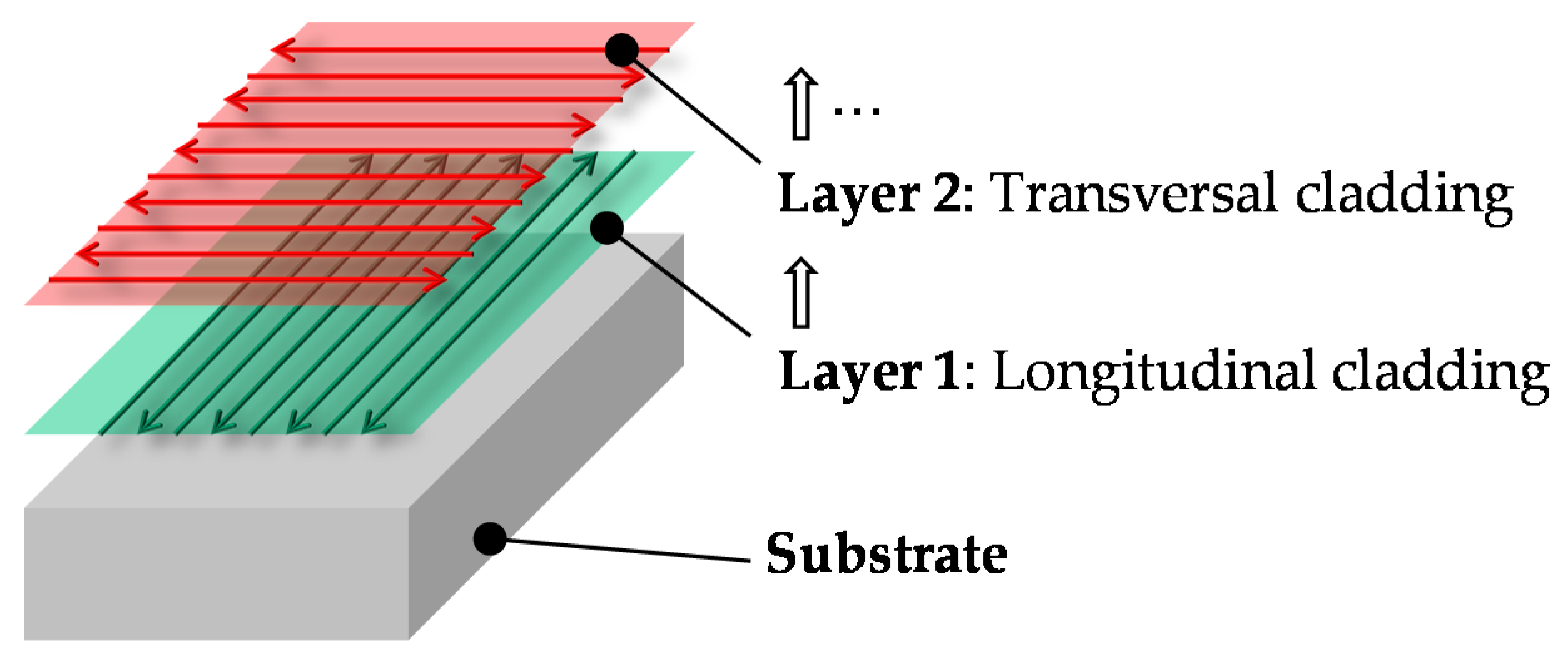
Once the channel is closed, AISI H13 is added by alternating longitudinal with transversal directions when laser cladding until the desired height is reached, as shown in
Figure 3. Directionality within the mechanical properties and residual stress of the deposited material that may lead to the generation of cracks are thereby avoided.
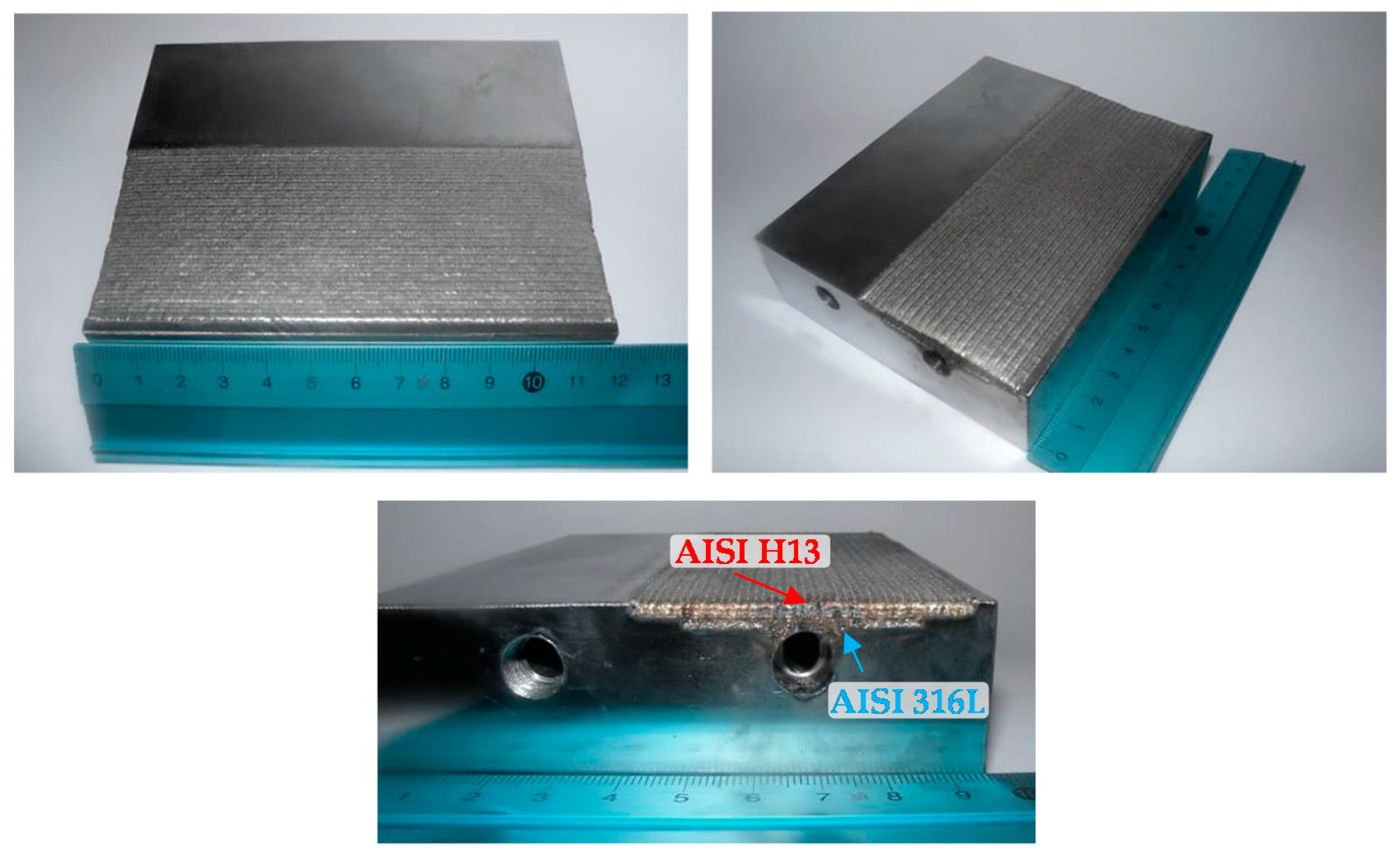
As far as the process parameters are concerned, different values are used for the deposition of each material and are presented in
Table 3, while the results attained when finishing the deposition of AISI 316L and AISI H13 are shown in
Figure 4.
Following the experiments, the part is hardened by heating at 1050 °C for 15 min and quenching in water. The component is then ground so that the desired surface quality is attained. In addition, drill holes of ten millimeters length are conducted and M10 fine threaded inside the channels in order to enable the threading of push in connectors and then proceed to the thermal and mechanical analyses.
Acknowledgments
This study was supported by the H2020-FoF13 PARADDISE Project (Grant Agreement No. 723440) and the ADDICLEAN Project (RTC-2015-4194-5) of the Spanish Ministry of Economy and Competitiveness and the University of the Basque Country (UPV/EHU). Special thanks are addressed to Batz S. Coop. Company (Igorre, Spain) for their technical support in this work.
Author Contributions
Jon Iñaki Arrizubieta and Magdalena Cortina conceived and designed the experiments; Jon Iñaki Arrizubieta, Magdalena Cortina and Amaia Calleja performed the experiments; Jon Iñaki Arrizubieta realized the thermal simulations and Magdalena Cortina analyzed the data; Eneko Ukar and Amaia Alberdi contributed materials/analysis tools; Magdalena Cortina wrote the paper.
Conflicts of Interest
The authors declare no conflict of interest.
References
- Jhavar, S.; Paul, C.P.; Jain, N.K. Causes of failure and repairing options for dies and molds: A review. Eng. Fail. Anal. 2013, 34, 519–535. [Google Scholar] [CrossRef]
- Altan, T.; Lilly, B.; Yen, Y.C.; Altan, T. Manufacturing of Dies and Molds. CIRP Ann. 2001, 50, 404–422. [Google Scholar] [CrossRef]
- Steinbeiss, H.; So, H.; Micheltisch, T.; Hoffmann, H. Method for Optimizing the Cooling Design of Hot Stamping Tools. Prod. Eng. 2007, 1, 149–155. [Google Scholar] [CrossRef]
- Eriksson, M.; Oldenburg, M.; Somani, M.C.; Karjalainen, L.P. Testing and Evaluation of Material Data for Analysis of Dorming and Hardening of Boron Steel Components. Model. Simul. Mater. Sci. Eng. 2002, 10, 277–294. [Google Scholar] [CrossRef]
- Hoffmann, H.; So, H.; Steinbeiss, H. Design of hot stamping tools with cooling system. CIRP Ann. 2007, 56, 269–272. [Google Scholar] [CrossRef]
- Hölker, R.; Jäger, A.; Tekkaya, A.E. Additive manufacturing of tools and dies for metal forming. In Laser Additive Manufacturing; Brandt, M., Ed.; Woodhead Publishing Series in Electronic and Optical Materials; Woodhead Publishing: Cambridge, UK, 2017; Volume 17, pp. 439–464. [Google Scholar]
- Shinde, M.S.; Ashtankar, K.M. Additive manufacturing-assisted conformal cooling channels in mold manufacturing processes. Adv. Mech. Eng. 2017, 9, 1–14. [Google Scholar] [CrossRef]
- Campanelli, S.L.; Angelastro, A.; Signorile, C.G.; Casalino, G. Investigation on direct laser powder deposition of 18 Ni (300) marage steel using mathematical model and experimental characterization. Int. J. Adv. Manuf. Technol. 2017, 89, 885–895. [Google Scholar] [CrossRef]
- Casalino, G.; Campanelli, S.L.; Contuzzi, N.; Ludovico, A.D. Experimental investigation and statistical optimisation of the selective laser melting process of a maraging steel. Opt. Laser Technol. 2015, 65, 151–158. [Google Scholar] [CrossRef]
- Schieck, F.; Hochmuth, C.; Polster, S.; Mosel, A. Modern tool design for component grading incorporating simulation models, efficient tool cooling concepts and tool coating systems. CIRP J. Manuf. Sci. Technol. 2011, 4, 189–199. [Google Scholar] [CrossRef]
- Hölker, R.; Haase, M.; Khalifa, N.B.; Tekkaya, A.E. Hot extrusion dies with conformal cooling channels produced by Additive Manufacturing. Mater. Today Proc. 2015, 2, 4838–4846. [Google Scholar] [CrossRef]
- Hölker, R.; Jäger, A.; Khalifa, N.B.; Tekkaya, A.E. New concepts for cooling of extrusion dies manufactured by rapid tooling. Key Eng. Mater. 2011, 491, 223–232. [Google Scholar] [CrossRef]
- Huskic, A.; Behrens, B.A.; Giedenbacher, J.; Huskic, A. Standzeituntersuchungen generative hergestellter Schmiedewerkzeuge. Schmiede J. 2013, 92013, 66–70. [Google Scholar]
- Huskic, A.; Giedenbacher, J.; Pschebezin, U.; Wild, N. Rapid Tooling für Umformwerkzeuge. RTejournal Forum für Rapid Technologie 2012. [Google Scholar]
- Ahn, D.G.; Kim, H.W.; Park, S.H. Manufacture of mould with a high energy efficiency using rapid manufacturing process. AIP Conf. Proc. 2010, 1252, 185–191. [Google Scholar]
- Müller, B. Konturnahe Temperierung beim Presshärten; Fraunhofer Institut für Werkzeugmaschinen und Umformtechnik (IWU): Chemnitz, Germany, 2013. [Google Scholar]
- Vollmer, R.; Kolleck, R.; Schwemberger, P. Herstellung oberflächennaher kühlkanalstrukturen für das presshärten mittels Laserauftragschweißen. In Proceedings of the Tagungsband zum 9. Erlanger Workshop Warmblechumformung, Erlangen, Germany, 18 November 2014; pp. 61–73. [Google Scholar]
- Arrizubieta, J.I.; Tabernero, I.; Ruiz, J.E.; Lamikiz, A.; Martínez, S.; Ukar, E. Continuous coaxial nozzle design for LMD based on numerical simulation. Phys. Procedia 2014, 56, 429–438. [Google Scholar] [CrossRef]
- Kind & Co Edelstahlwerk. CR7V-L Datasheet. Available online: http://www.kind-co.de/en/download-centre.html (accessed on 17 September 2017).
- Uddeholm. Orvar Supreme Datasheet. Available online: http://www.uddeholm.com/files/PB_orvar_supreme_english.pdf (accessed on 17 September 2017).
- Metallied Powder Solutions SA. Pearl® Micro 316L Datasheet; Metallied Powder Solutions SA: San Sebastian, Spain, 2015. [Google Scholar]
- AK Steel Corporation. 316/316L Stainless Steel Datasheet. Available online: http://www.aksteel.com/pdf/markets_products/stainless/austenitic/316_316l_data_sheet.pdf (accessed on 28 September 2017).
- Sandmeyer Steel Company. Specification Sheet: Alloy 316/316L. Available online: https://www.sandmeyersteel.com/images/316-316l-317l-spec-sheet.pdf (accessed on 28 September 2017).
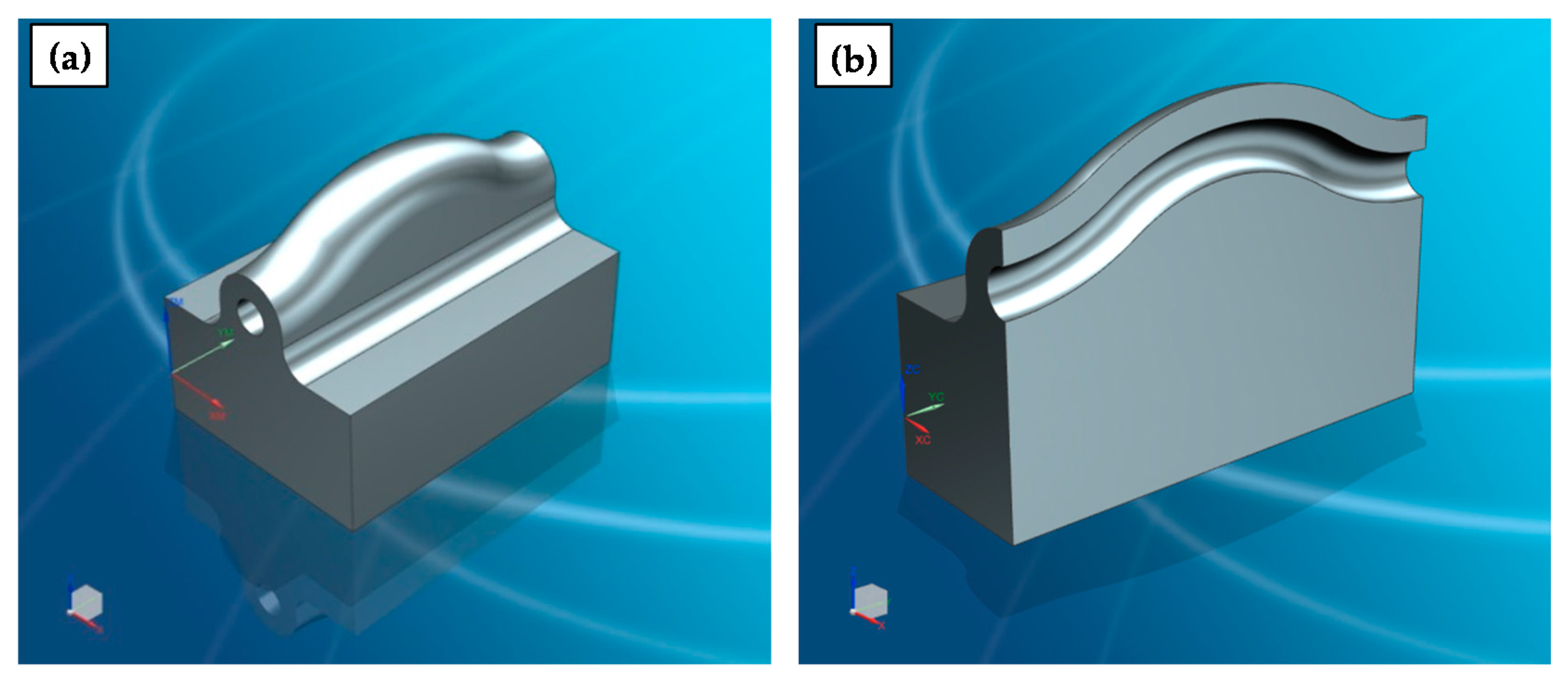
Figure 1.
(a) Substrate before LMD; (b) Computer Aided Design (CAD) model to be processed.
Figure 2.
Deposition strategy of the AISI 316L intermediate layer.
Figure 3.
Deposition strategy of AISI H13.
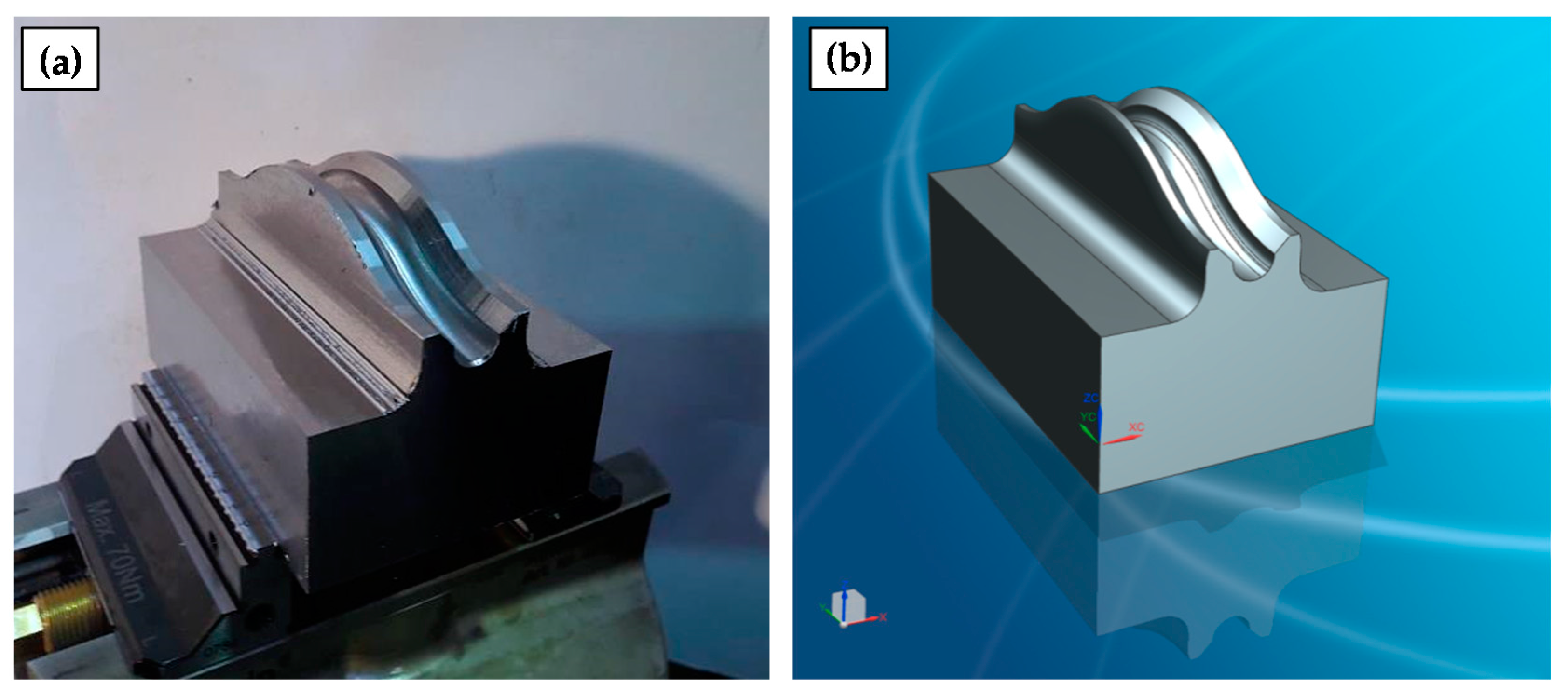
Figure 4.
Final part after finishing the LMD process.
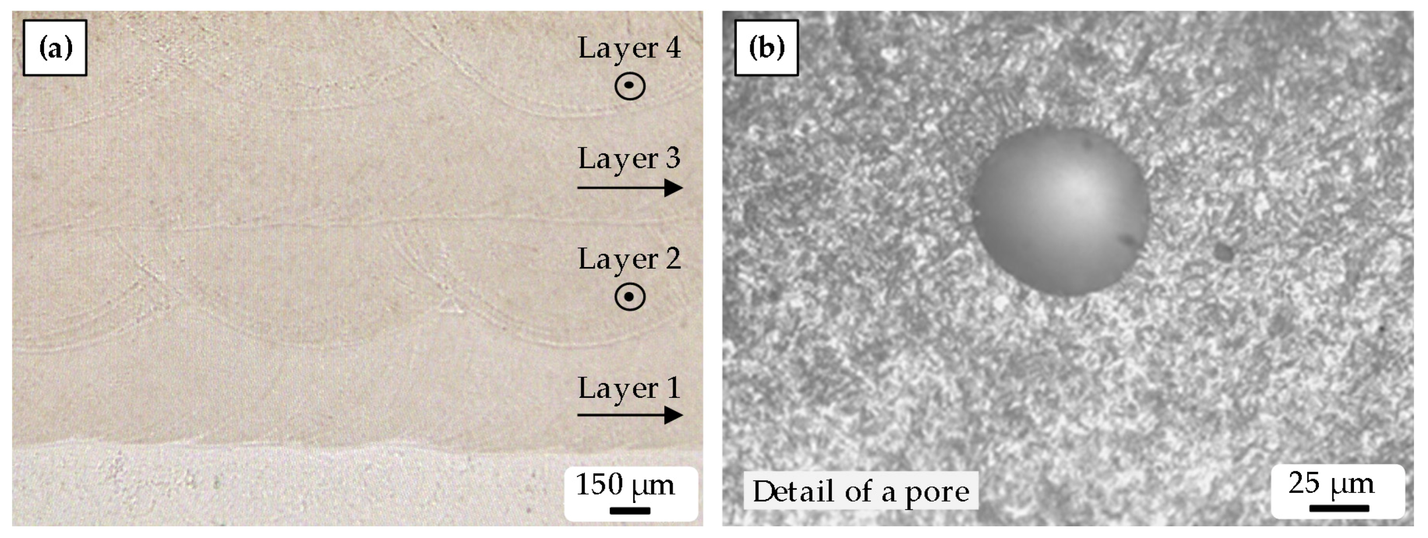
Figure 5.
Metallography of the (a) deposited layers; (b) detail of a pore.
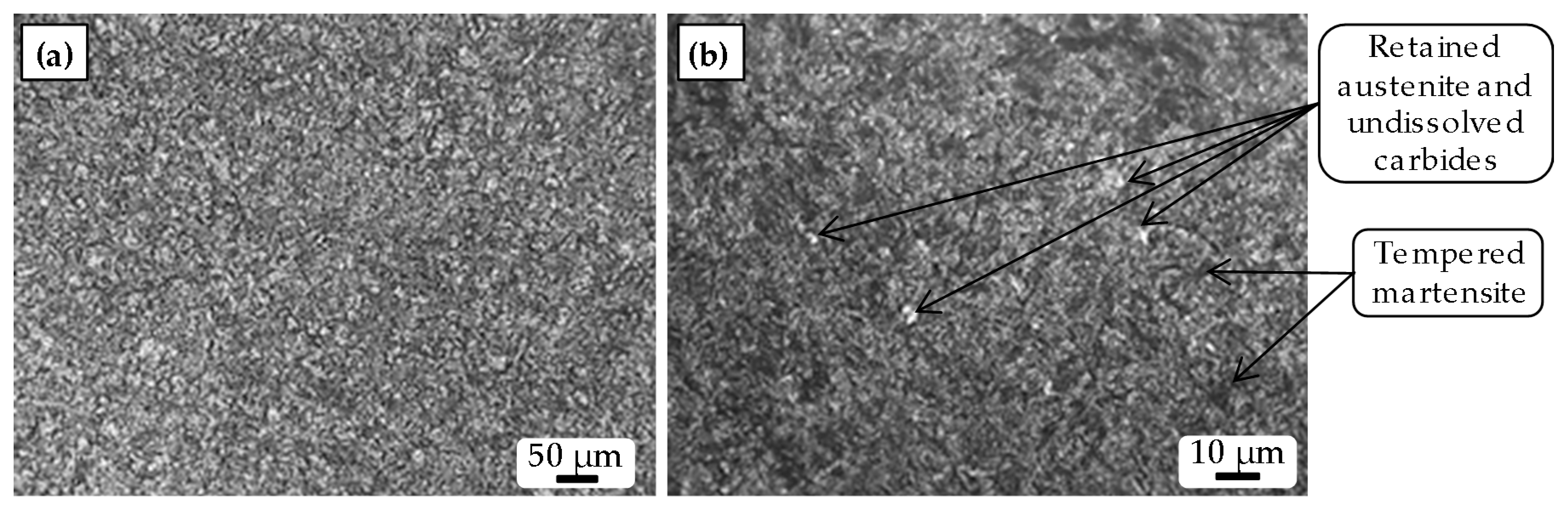
Figure 6.
Microstructure of (a) the substrate; (b) the deposited material.
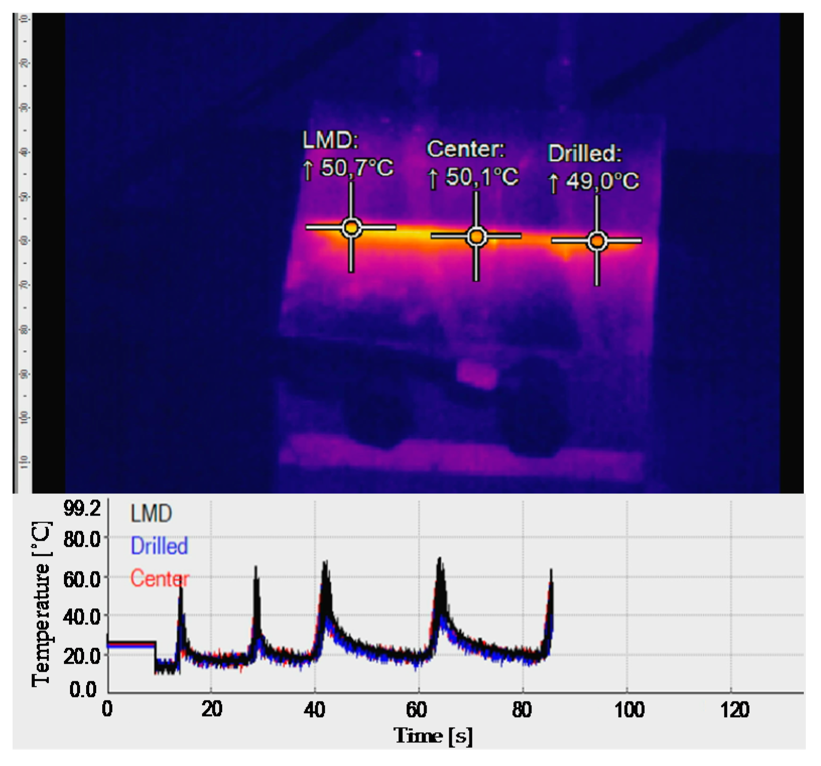
Figure 7.
Cooling capacity when laser and water-cooling are both active.
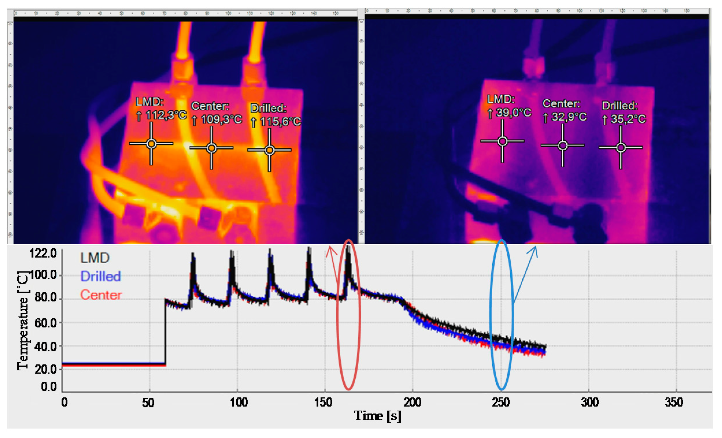
Figure 8.
Cooling capacity when the water-cooling is active after reaching 100 °C.
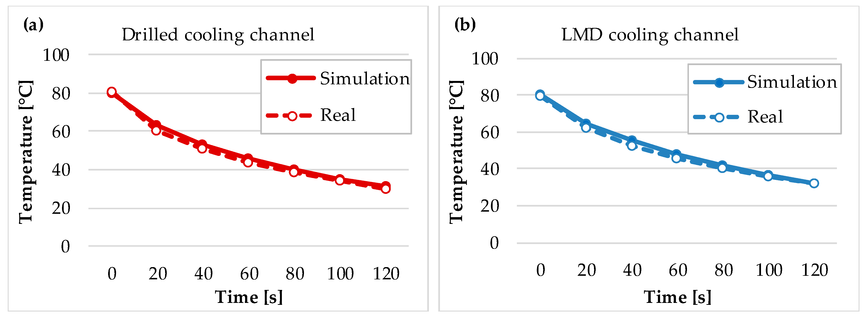
Figure 9.
Simulation and real results for (a) drilled; (b) LMD cooling channels.
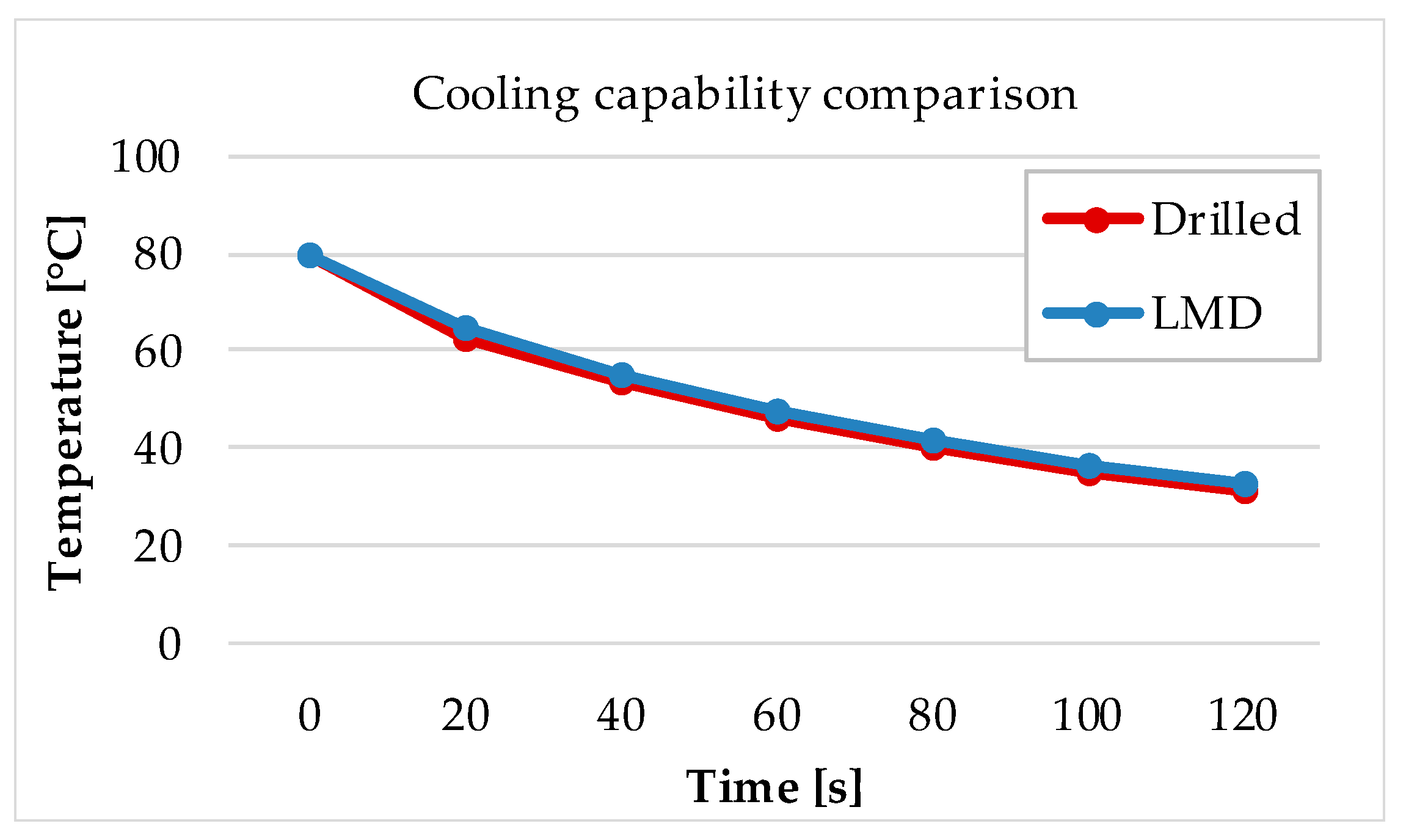
Figure 10.
Cooling capacity comparison between the drilled and the LMD channels.
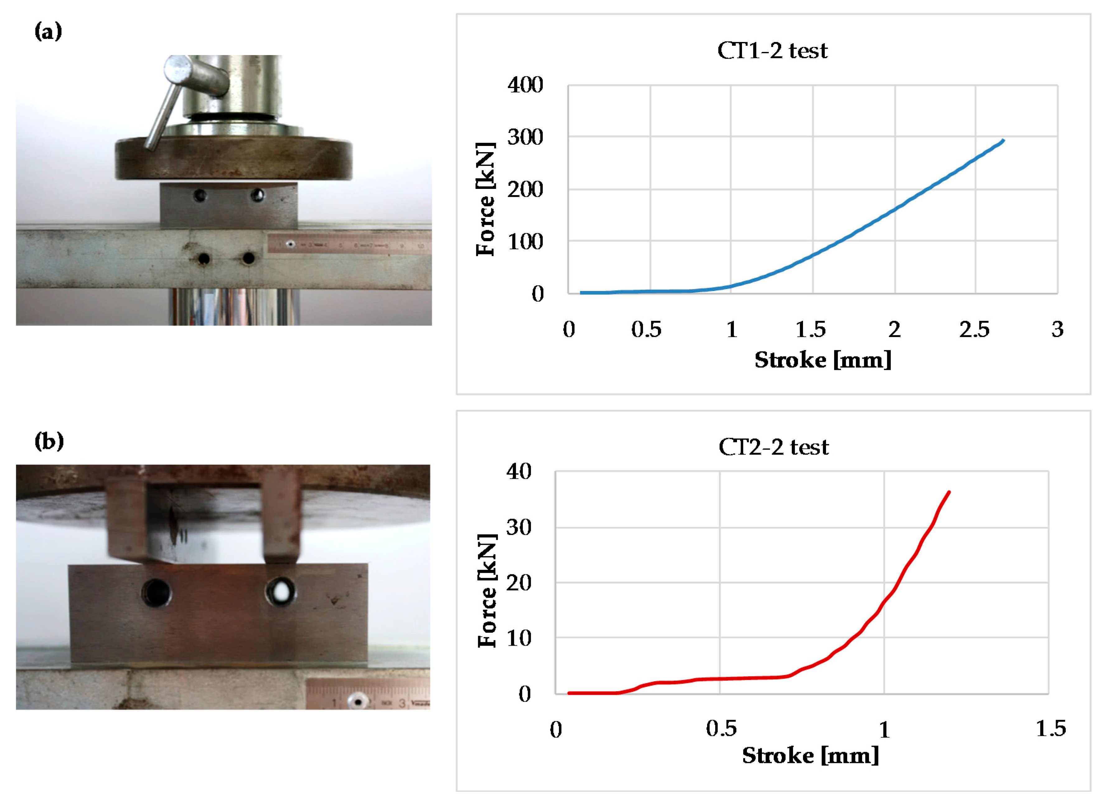
Figure 11.
(a) CT1-2; (b) CT2-2 set-ups and results.
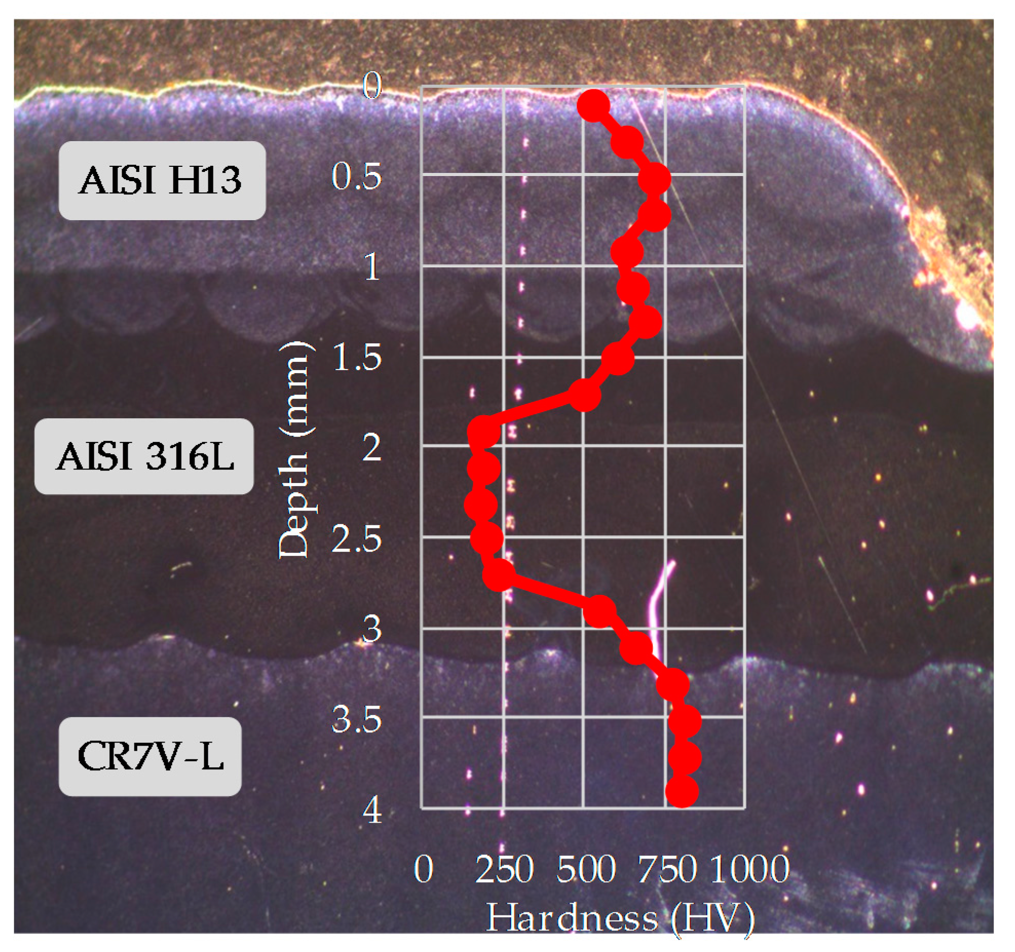
Figure 12.
Vickers hardness values of the deposited materials and substrate.
Figure 13.
(a) Isometric view; (b) cross section of the 3D conformal cooling CAD model.
Figure 14.
(a) Substrate before LMD; (b) CAD model after the preparatory machining.
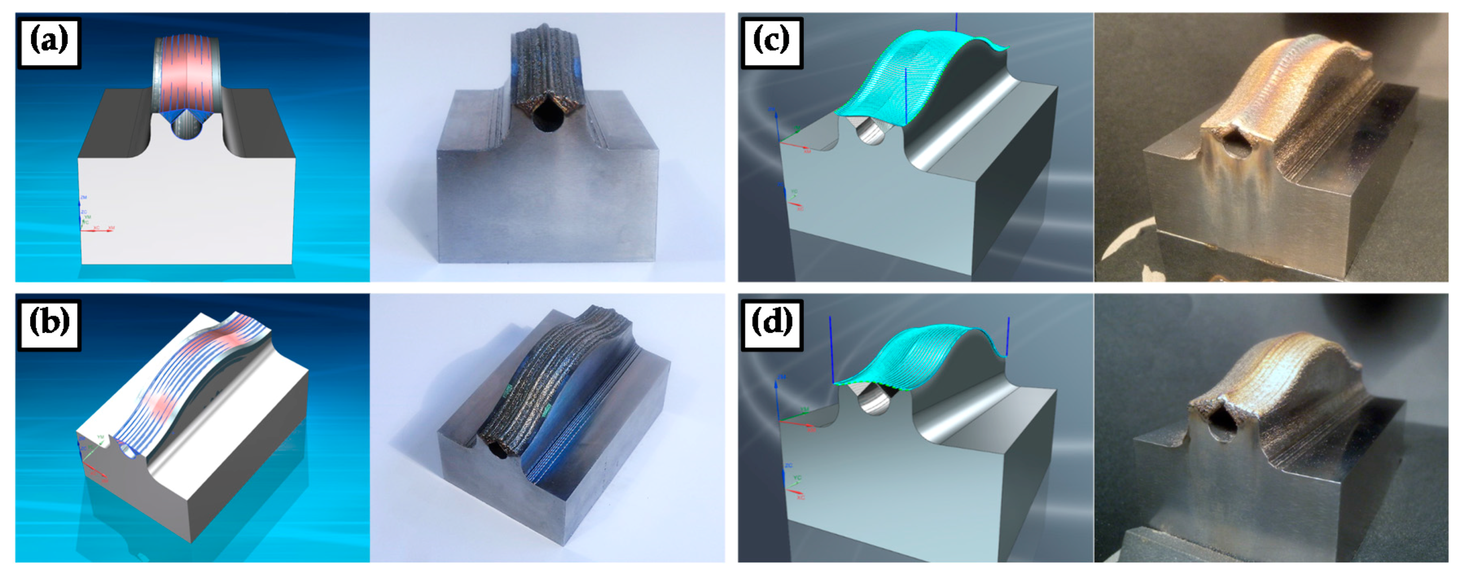
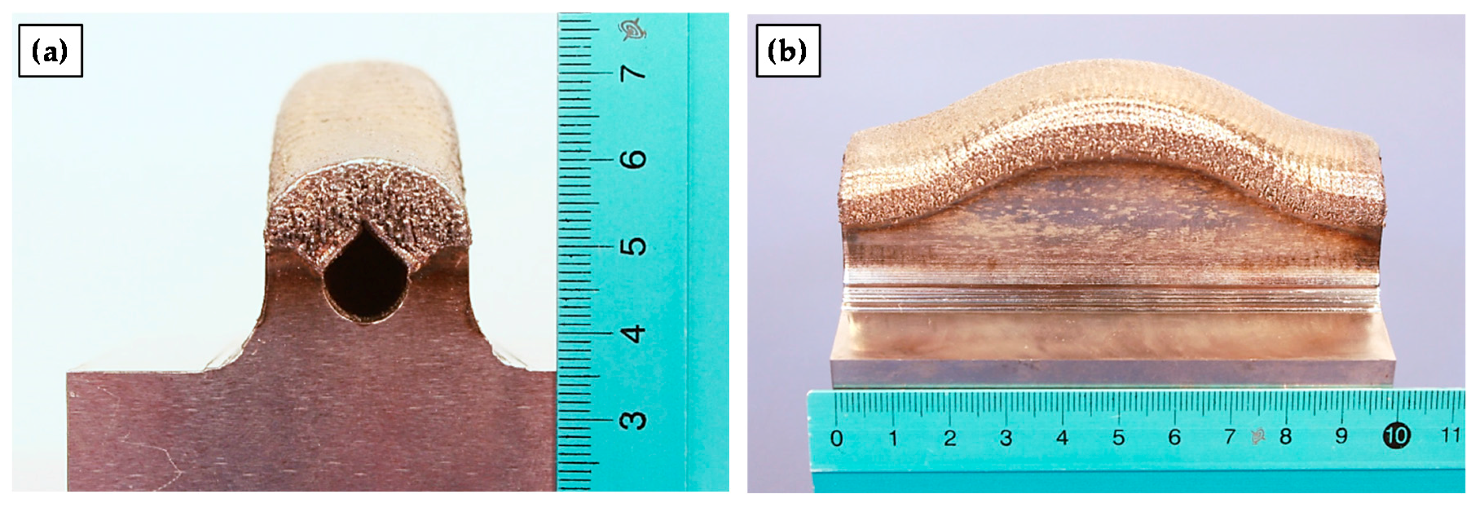
Figure 15.
(a) Front; (b) lateral views of the resulting part after LMD; (c) transversal LMD; (d) longitudinal LMD.
Figure 16.
(a) Front; (b) lateral views of the resulting part after LMD.
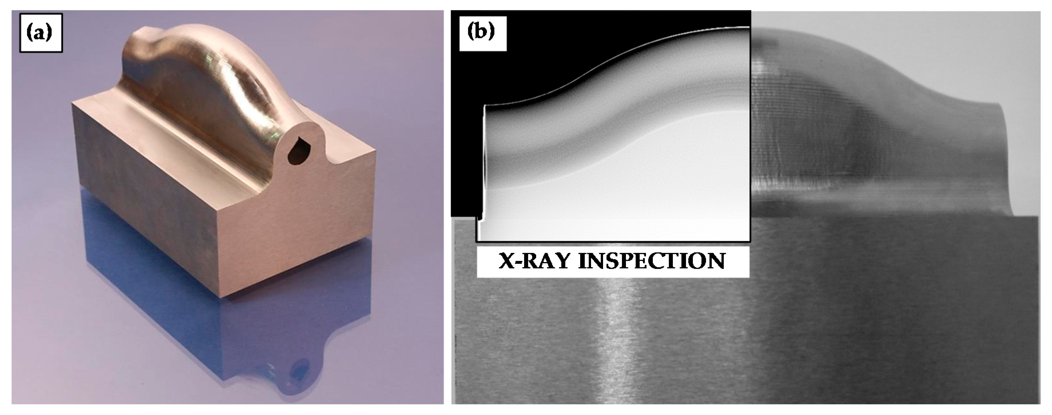
Figure 17.
(a) Final part; (b) X-ray inspection.
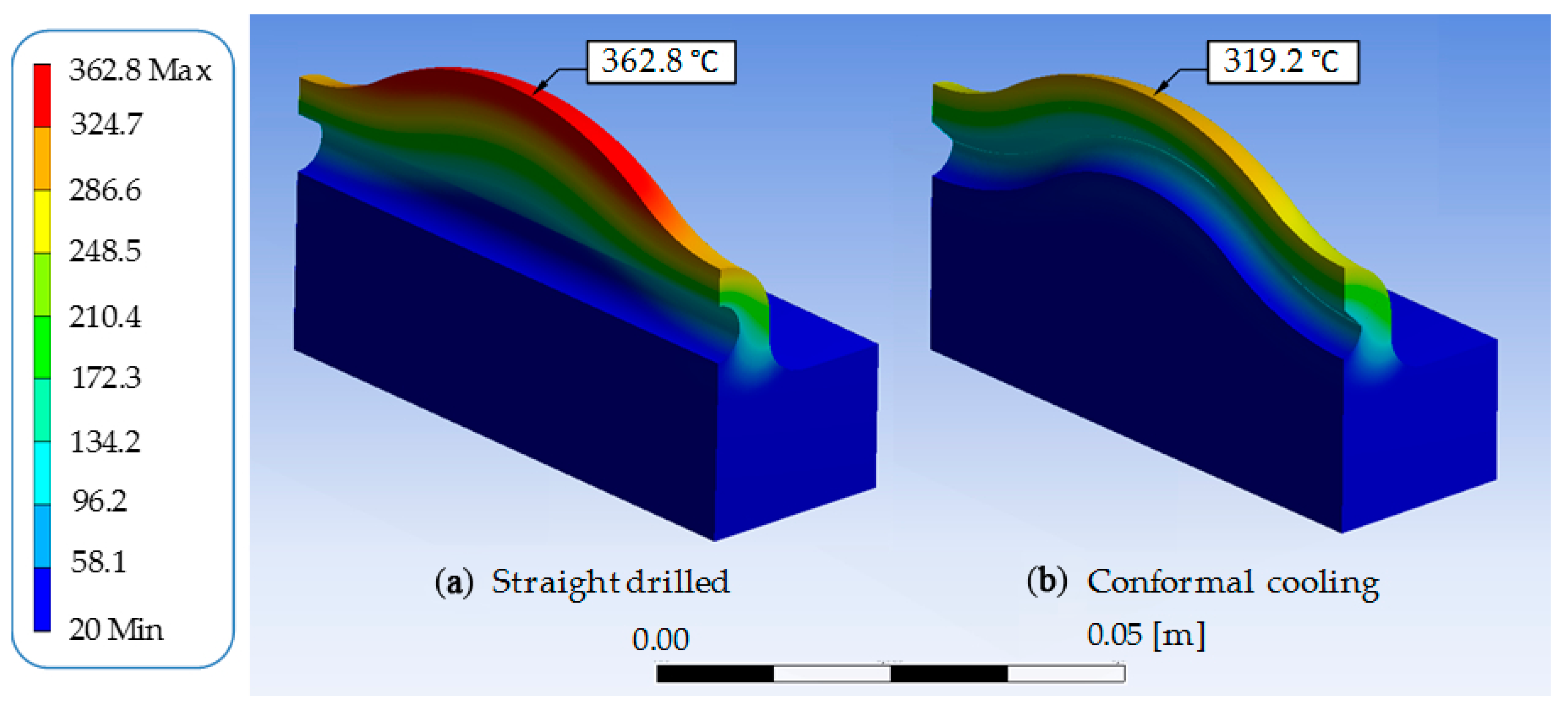
Figure 18.
Thermal simulation results of conventional drilled (a) vs. conformal (b) cooling.
Table 1.
Chemical composition (wt. %) of the used materials, data from [
19,
20,
21,
22].
| Material | C | Si | Mn | Cr | Mo | V | Ni | P | Fe |
|---|
| CR7V-L | 0.42 | 0.50 | 0.40 | 6.50 | 1.30 | 0.80 | - | - | Balance |
| AISI H13 | 0.39 | 1.00 | 0.40 | 5.20 | 1.40 | 0.90 | - | - | Balance |
| AISI 316L | 0.0023 | 0.34 | 0.079 | 18.15 | 2.33 | - | 11.75 | <0.001 | Balance |
Table 2.
Thermal properties of the used materials, data from [
19,
20,
21,
22].
| Material | Temperature (°C) | 20 | 400 | 600 |
|---|
| CR7V-L | Thermal conductivity (W·m−1·K−1) | 26.7 | 30.8 | 30.8 |
| | Coefficient of thermal expansion (10−6 K−1) | 11.2 | 12.5 | 13.1 |
| AISI H13 | Thermal conductivity (W·m−1·K−1) | 25 | 29 | 30 |
| | Coefficient of thermal expansion (10−6 K−1) | - | 12.6 | 13.2 |
| AISI 316L | Thermal conductivity (W·m−1·K−1) | 15.3 | 20.1 | 22.7 |
| | Coefficient of thermal expansion (10−6 K−1) | 16 | 17.5 | 18.5 |
Table 3.
Laser Metal Deposition (LMD) process parameters regarding deposited materials.
| Process Parameters | AISI 316L | AISI H13 |
|---|
| Continuous wave (CW) laser power (W) | 625 | 600 |
| Scan velocity (mm·min−1) | 550 | 450 |
| Track offset (mm) | 1.4 | 1 |
| Overlap (%) | 30 | 50 |
| Powder flow rate (g·min−1) | 5 | 3.3 |
| Powder preheating temperature (°C) | 60 |
| Protective gas flow rate (L·min−1) | 14 |
Table 4.
Technical characteristics of the compressive machine.
| Technical Characteristics of the SDE Compressive Machine (MEM-101/SDC) |
|---|
| Capacity (kN) | 300 |
| Maximum velocity (mm·min−1) | 40 |
| Stroke (mm) | 400 |
Table 5.
Realized compression tests.
| Test | Applied Pressure (MPa) | Surface (mm2) | Applied Force (kN) |
|---|
| CT1-1 | 15 | 11,677.5 | 175.16 |
| CT1-2 | 25 | 11,677.5 | 291.94 |
| CT2-1 | 15 | 2404 | 36.06 |
| CT2-2 | 30 | 2404 | 72.12 |
© 2018 by the authors. Licensee MDPI, Basel, Switzerland. This article is an open access article distributed under the terms and conditions of the Creative Commons Attribution (CC BY) license (http://creativecommons.org/licenses/by/4.0/).

 ,
, 


