Microstructural and Corrosion Properties of Cold Rolled Laser Welded UNS S32750 Duplex Stainless Steel
by
 ,
,
Claudio Gennari
1 ,
,
Mattia Lago
1,
Balint Bögre
2,
Istvan Meszaros
2,
Irene Calliari
1,* and 
Luca Pezzato
1 1
Department of Industrial Engineering, University of Padova, Via Marzolo 9, 35131 Padova PD, Italy
2
Department of Materials Science and Engineering, Budapest University of Technology and Economics, Bertalan Lajos utca 7, 1111 Budapest, Hungary
*
Author to whom correspondence should be addressed.
Metals 2018, 8(12), 1074; https://doi.org/10.3390/met8121074
Submission received: 13 November 2018
/
Revised: 14 December 2018
/
Accepted: 15 December 2018
/
Published: 18 December 2018
(This article belongs to the Special Issue Manufacturing and Application of Stainless Steels)
Abstract
:The main goal of this work was to study the effect of plastic deformation on weldability of duplex stainless steel (DSS). It is well known that plastic deformation prior to thermal cycles can enhance secondary phase precipitation in DSS which can lead to significant change of the ferrite-austenite phase ratio. From this point of view one of the most important phase transformation in DSS is the eutectoid decomposition of ferrite. Duplex stainless steels (DSSs) are a category of stainless steels which are employed in all kinds of applications where high strength and excellent corrosion resistance are both required. This favorable combination of properties is provided by their biphasic microstructure, consisting of ferrite and austenite in approximately equal volume fractions. Nevertheless, these materials may suffer from several microstructural transformations if they undergo heat treatments, welding processes or thermal cycles. These transformations modify the balanced phase ratio, compromising the corrosion and mechanical properties of the material. In this paper, the microstructural stability as a consequence of heat history due to welding processes has been investigated for a super duplex stainless steel (SDSS) UNS S32750. During this work, the effects of laser beam welding on cold rolled UNS S32750 SDSS have been investigated. Samples have been cold rolled at different thickness reduction (ε = 9.6%, 21.1%, 29.6%, 39.4%, 49.5%, and 60.3%) and then welded using Nd:YAG laser. Optical and electronical microscopy, eddy’s current tests, microhardness tests, and critical pitting temperature tests have been performed on the welded samples to analyze the microstructure, ferrite content, hardness, and corrosion resistance. Results show that laser welded joints had a strongly unbalanced microstructure, mostly consisting of ferritic phase (~60%). Ferrite content decreases with increasing distance from the middle of the joint. The heat-affected zone (HAZ) was almost undetectable and no defects or secondary phases have been observed. Both hardness and corrosion susceptibility of the joints increase. Plastic deformation had no effects on microstructure, hardness or corrosion resistance of the joints, but resulted in higher hardness of the base material. Cold rolling process instead, influences the corrosion resistance of the base material.
1. Introduction
Duplex stainless steels (DSSs) are a group of steel with a ferrite and austenite biphasic microstructure. They are widely used in very aggressive environment like nuclear and petrochemical plants, oil and gas offshore applications, chemical plants, paper and pulp industries, food and beverages industries as an alternative to the austenitic stainless steels [1,2,3,4]. They have higher mechanical properties and corrosion resistance compared to the austenitic stainless steels but suffer from secondary phases embrittlement and cannot be used at temperature higher than 350 °C [5,6].
The optimum properties of super duplex stainless steels are achieved when approximately equal amounts of ferrite and austenite are present in the microstructure. This balanced ratio between the two phases is obtained with a suitable combination of chemical composition and solution heat treatment [3,7]. However, during welding processes the microstructure can undergo detrimental transformations. DSSs solidifies starting from a fully ferritic microstructure and, as the material cools to room temperature, ferrite transforms into austenite through solid-state transformation [1,2,3,4,7,8]. With an improper cooling rate, two main problems may arise: an unbalanced austenite–ferrite ratio, and the precipitation of secondary phases in the weld zone (WZ) and heat-affected zone (HAZ) [9] which can both affect the mechanical properties, in particular impact toughness [10,11,12,13] and corrosion resistance [14,15].
Solution heat treatment is necessary in order to obtain a balanced microstructure and to solubilize any possible secondary phases that has been formed. Secondary phases can precipitate in a temperature range between 600 °C and 1000 °C. At lower temperature, typically 475 °C, ferrite spinodal decomposition can occur if the holding time is long enough (higher than 100 h). Main secondary phases that can precipitate are σ phase, χ phase, and chromium nitrides (i.e., Cr2N) and the less common R-phase, π-phase, Laves phase, and carbides, not to mention secondary austenite decomposition and spinodal ferrite decomposition [4].
Even though it is thermodynamically unstable, the first phase to precipitate is χ phase thanks to its lattice parameter close to three times that of ferrite, followed by σ-phase. Both σ-phase and χ-phase grow toward the ferrite, eventually consuming all of it [3,13,16]. Because of its higher content in high atomic number element (i.e., molybdenum and chromium) those secondary phases appear lighter in backscattered-electrons. Chromium nitrides, on the other hand, appear as a dark chain because of the lower atomic number of the constituent. They are located at the ferrite/ferrite grain boundary and the ferrite/austenite phase boundaries. Nitrogen solubility in ferrite is considerably lower compared to austenite, moreover, it drops as the temperature decreases hindering the diffusion of nitrogen atoms in the austenite resulting in chromium nitrides precipitation [3].
Therefore, the study of weldability of super duplex stainless steels is a fundamental task for their proper industrial application. Previous investigation showed that conventional welding processes as submerged arc welding (SAW) [17,18,19], plasma arc welding (PAW) [20,21,22], gas tungsten arc welding (GTAW) [23,24,25], and friction stir welding (FSW) [26,27,28] have a highly affected austenite-ferrite ratio, promoting precipitation of secondary harmful phases. For this reason, high power laser welding has seen a remarkable increase in research interest, due to its better precision, speed, and versatility compared to traditional welding processes [29,30,31]. While earlier researchers studied the effect of laser beam parameters on microstructure and properties of DSSs [8,9,32,33], few papers addressed ferrite–austenite ratio change in SDSS welding [34,35,36,37].
In this work, the effects of Nd:YAG laser welding on microstructure and mechanical and corrosion properties of UNS S32750 SDSS samples with seven different grades of thickness reduction (ε = 0%, 9.6%, 21.1%, 29.6%, 39.4%, 49.5%, and 60.3%) are studied.
2. Materials and Methods
The UNS S32750 super duplex stainless steel were kindly supplied by ArcelorMittal (ArcelorMittal S.A., Luxembourg, Luxembourg). Its composition is reported in Table 1.
The as received material was a 15 mm thickness plate, previously solution annealed at 1100 °C for 1 h and water quenched. Three sets of seven specimens 100 mm long and 10 mm wide were cut to undergo plastic deformation through cold rolling process. The samples were deformed along the hot rolling direction, using a double cylinder mill with a reduction per pass of 0.25 mm. The 9.6%, 21.1%, 29.6%, 39.4%, 49.9% and 60.3% thickness reductions were applied, and the average strain rate was 0.15 s−1.
To perform the laser beam welding each specimen was milled to the dimension of 70 × 15 × 3 mm. The welds were performed with a 4 kW Rofin-Sinar DY 044 Nd:YAG laser (ROFIN-SINAR Laser Gmb, Hamburg, Germany) assisted with a six-axis robot from ABB (ABB Asea Brown Boveri Ltd., Zurich, Switzerland). To prevent distortion while welding, the samples were clamped to the workbench. The shielding gas used was argon with a purity of 99.995%.
All the specimens were butt-welded using the weld parameters summarized in Table 2 in order to achieve full penetration of the welds.
After the welding process, the specimens were cut transversal with respect to the weld direction for the metallographic analysis. Microhardness tests were performed in the cross surfaces of the welded samples following ASTM E384 standard using a Buehler IndentaMetTM 1105 (ITW Test & Measurement GmbH, Esslingen, Germany) with a load of 300 g and an application time of 11 s. Corrosion resistance was evaluated on the surface of both welded and unwelded samples testing the weld bead surface and the longitudinal section of the unwelded sample. The content of ferrite in the weld bead was measured with Eddy’s current test (ECT) (Test Maschinen Technik GmbH, Schwarmstedt, Germany).
Eddy-current testing (ECT) is a non-destructive electromagnetic test method, which uses electromagnetic induction to detect and characterize surface and sub-surface flaws, as well as ferromagnetic phase content in conductive materials. In an eddy current probe, a coil of conductive wire is excited with an alternating electrical current. This current produces an alternating magnetic field around the coil, which oscillates at the same frequency of the current. If the probe and its magnetic field are placed close to a conductive material a circular flow of electrons, known as an eddy current, will begin to move through the metal. That eddy current flowing through the metal will, in turn, generate its own magnetic field, which will interact with the coil and its field through mutual inductance. Changes in metal thickness or defects, like near-surface cracks, will interrupt or alter the amplitude and pattern of the eddy current and the resulting magnetic field. This in turn affects the movement of electrons in the coil by varying its electrical impedance. Changes in the impedance amplitude and phase angle can be correlated with the volume fraction of magnetic phase in the material.
To analyze the microstructure of the welds, all the samples were first mounted on a phenolic resin and then grinded to 1200 grit SiC paper and polished with diamond suspensions (6 µm and 1 µm) to a mirror like surface finish. After the polishing process, the samples were electrolytically etched at voltage ranging from 2 to 20 V with 20% sodium hydroxide to distinguish austenite from ferrite since the last one is preferentially etched.
The metallographic analysis was then performed with a Leica DMRE optical microscope and with a Leica Cambridge Stereoscan 440 scanning electron microscope (Leica Microsystems S.r.l., Milan, Italy) operating in secondary electron (15 kV) and backscattered electron (29 kV).
The corrosion resistance was evaluated by mean of the critical pitting temperature test (CPT) in order to correlate the microstructure modifications to the corrosion properties [15].
The CPT was determined following the ASTM G150 standard. A potentiostat AMEL 7060 (Amel Electrochemistry, Milan, Italy) was used, the equipment consisted of two cells, containing the same aqueous solution (1 M of NaCl), and electrically connected by a salt bridge; in the first cell, maintained at room temperature, the reference electrode (calomel) was immersed, whereas the counter electrode (platinum) and the sample were placed in the second cell, where the temperature was controlled by a thermostatic bath.
The ASTM G150 standard involves the evaluation of the CPT by maintaining a constant anodic potential of 700 mV vs. SCE and increasing the temperature of the thermostatic cell at the rate of 1 °C/min. Before the test the open circuit potential (OCP) was evaluated letting the system stabilize for 60 min. The CPT is determined when the current density reaches 100 µA/cm2 and remains above this level for a minimum of 60 s. The tests were conducted until the occurrence of stable pitting and then stopped to prevent excessive corrosion of the specimen.
The CPT determination was performed both for un-welded and welded samples, by exposing 1 cm2. The samples were varnished with a thermal-resistant varnish letting exposed the selected area. This area includes both the WZ and the HAZ due to the low dimensions of the HAZ in this type of welds. The corroded samples were then analyzed with a stereomicroscope Zeiss Stereoscan Stemi C2000 (Carl Zeiss S.p.A., Milan, Italy).
To determine the ferrite content on the welded samples, 13 ECT measurements were performed on the top section of each sample, starting from the middle of the joint. The distance between each detection point was 1 mm. The inspection was done at 4 different frequencies: 10.0 kHz, 40.0 kHz, 66.7 kHz and 100.0 kHz. The data acquisition, processing and the control of the set-up were done with ScanMax software (Test Maschinen Technik GmbH, Schwarmstedt, Germany).
3. Results and Discussions
3.1. Mictrostructure
The microstructure of the UNS S32750 SDSS base material is shown in Figure 1. The picture depicts a biphasic microstructure with approximately equal volume fraction of ferrite and austenite. Austenite phase (white) is orientated along the rolling direction (black arrow) dispersed in a ferrite matrix (blue–brown).
The microstructure of the weld bead cross section in Figure 2 confirms the peculiarity of laser beam welding, where the development of the microstructure is essentially symmetrical with respect to the axis of the laser beam [9]. The Y-type shape weld bead is a consequence of a relatively low welding speed (450 mm/min), conversely to the classical V-type shape for welding speed greater than 2000 mm/min [38]. Elongated ferrite grains along the heat flux direction with austenite dispersed inside and along ferritic grain boundaries are evident. The highly oriented and elongated shape of ferritic grains is due to the high cooling rate, estimated to be approximately 1000 °C/s [9,29,39]. Because of this remarkable cooling rate, the HAZ (region between dashed lines in Figure 3) was almost undetectable. The temperature reached in the weld zone was supposed to be approximately 1400 °C [8] even though some researchers found to be as high as 1800 °C [30].
One of the weld’s critical regions is the HAZ, depicted in Figure 3. The fusion line is continuous and clear, with the ferritic grains emanated from the base material grains as well as the austenitic grains. The HAZ zone (between dashed lines) is very narrow due to the high heat input of the laser and its spot size. The temperature reached in the HAZ is not high enough to melt the material, but it is high enough to modify the phase balance towards ferrite (i.e., phase balance is temperature and composition dependent, for this grade of DSS, a balanced microstructure is usually obtained at approximately 1050 °C). Fragmentation of austenite grains inside the dashed line is due to the temperature reached in this region which, as stated before, changed the phase balance of the base material toward ferrite since DSS starts to solidify from a fully ferritic microstructure. The segmentation of some austenitic-ferritic phase boundary (ellipses) is probably because the temperature reached in that region was high enough to start the dissolution of austenite inside the ferrite but not for long enough time to completely solubilize the austenite.
In agreement with the CCT diagram of σ-phase precipitation for a UNS S32750 [39], no precipitates were observed in this region, as can be seen from the scanning electron micrograph in backscattered electrons in Figure 4.
Secondary phases should appear as a lighter spot located mostly at the triple points between ferrite grains and at austenite–ferrite phase boundaries, while chromium nitrides should appear as dark chains at ferrite/ferrite grain boundaries. In this case, the dark appearance of both austenite and ferrite grain boundaries of Figure 4 is due to the etching, it would not be possible otherwise to distinguish austenite from ferrite because of the similar composition of the phases that results in low contrast on backscattered electrons images. Previous SEM-WDS examinations have been performed without etching, asserting the absence of chromium nitrides. In the welded region, deformation does not influence the precipitation of secondary phases. In fact, the results are similar to the one reported in Figure 4 for the undeformed sample with no secondary phases or chromium nitrides detected, due to high cooling rate for all the samples.
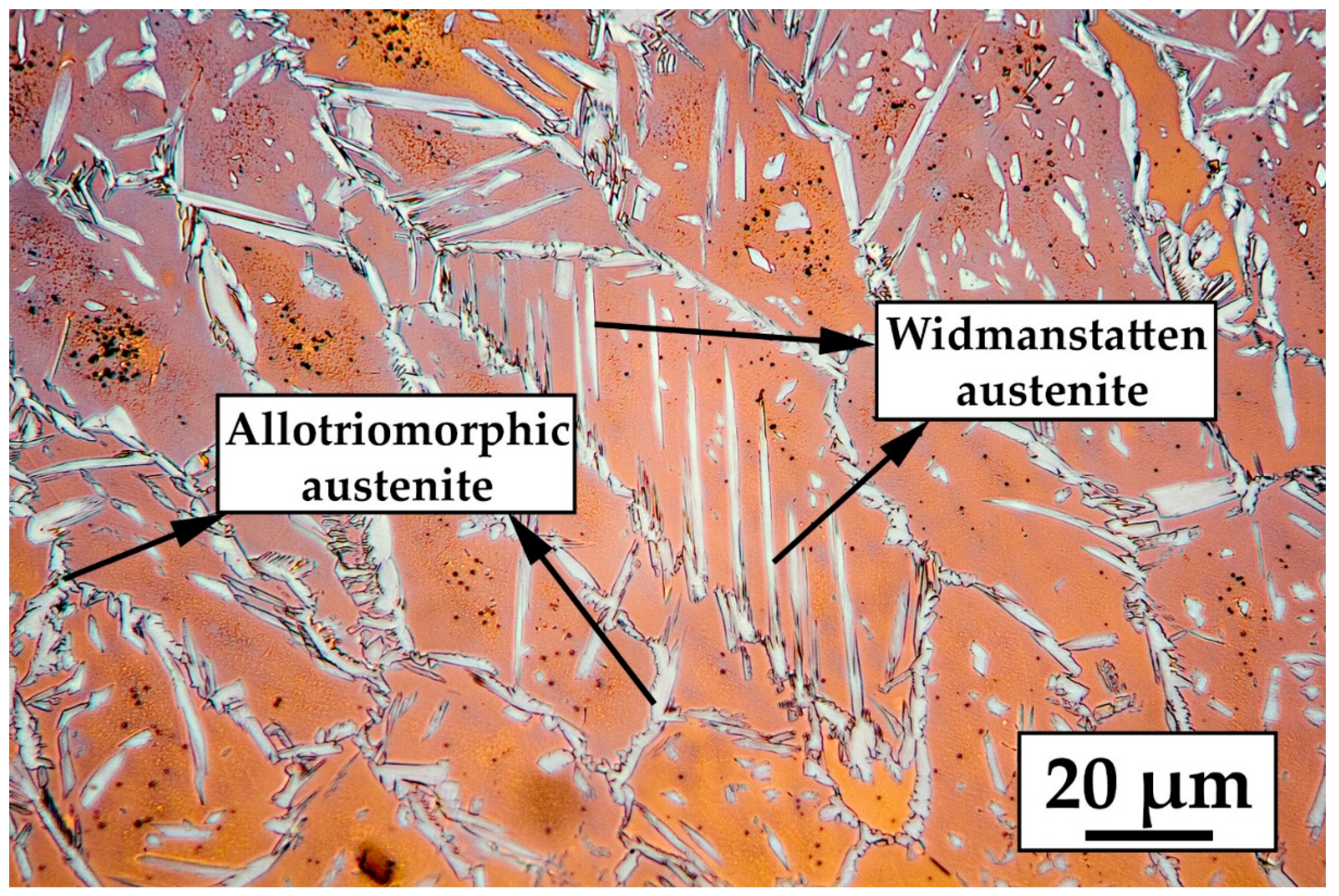
As previously mentioned, the weld zone solidifies initially fully ferritically and partially transforms into austenite through solid-state transformation as the temperature decreases. Because of the high cooling rate of laser welding, this transformation tends to be inhibited, resulting in a strongly unbalanced microstructure mostly consisting of ferritic phase [8,9,29]. It is clear from the micrographs in Figure 5 that the welded zone is mainly composed of massive ferrite grains, with a low volume fraction of austenite that grew both at ferrite grain boundaries and within the ferrite grains. Austenite nucleated at ferrite grain boundaries is allotriomorphic austenite while the elongate needle-like grains that grows from the grain boundary towards the ferritic grains is Widmanstätten austenite (Figure 5). The polygonal grains of austenite inside ferritic grains could be isomorphic austenite, Widmanstätten austenite emanated from the grain boundary below the surface or fragmented Widmanstätten austenite due to the decomposition of the austenite phase at lower temperatures as other researchers found [40,41].
In order to observe the influence of cold working on the austenite, it was necessary to extend the etching time which caused the saturation of ferrite with etching products. The higher the thickness reduction the higher the density of slip bands inside austenite and ferrite (Figure 6b,e,f). In low stacking fault energy phases, dislocations are split into partial, thus they can only move by gliding in its own crystal plane. This produces a planar distribution of dislocations among the same crystal. Slip bands are a direct consequence of this distribution, in which a lot of dislocation are piled up. Usually this does not happen in high stacking fault energy phases (i.e., ferrite), but due to the presence of austenite and its crystallographic compatibility with ferrite (Kurdjumov–Sachs crystallographic orientation) it is possible that piled up dislocation at austenite/ferrite interfaces will extend to the ferrite grains [42].
3.2. Microhardenss
Microhardness evolution in the welded region, in the heat affected zone and in the base material is depicted in Figure 7. Microhardness of the base material (blue line) it is clear the ascending trend due to strain hardening which lead to generation and interaction of dislocations, causing an inevitable increase in hardness [30,43,44]. The microhardness in the welded region is approximately 300 HV and it is not related to the different thickness reduction. This is obviously due to the fact that the material melts, so the previous plastic deformation does not influence the hardness of the region. The hardness of the HAZ is slightly lower than that of the welded region because, even though the region is very narrow, the heat input due to the welding process fully recovers the plastic deformation (the hardness of the HAZ does not follow the trend of the base material) as well as partial austenite dissolutions which changes the phase balance toward ferrite, as can be seen in Figure 3.
Overall the hardness of the welded region and the HAZ is higher compared to the un-deformed base material. This is related to the volume fraction of ferrite which is higher in the HAZ and in the welded region compared to the base metal.
3.3. Corrosion Pitting Temperature (CPT)
The determination of the critical pitting temperature allows determining a very useful parameter that can be used to find the best material for applications in chlorinated environments.
The results of the CPT tests performed on the as received plate and on the cold rolled samples both welded and unwelded, are reported in Figure 8 and Figure 9 and in Table 3 and Table 4. The results in the tables are the average obtained from three measurements for each sample.
The cold rolling process and the welding affect the corrosion resistance by lowering the CPT [14,45]. The increase in deformation causes a gradual drop of the CPT as can be observed in Table 4: the higher the thickness reduction the lower the CPT as shown by the measurement done in the unwelded samples. CPT varies from a maximum of 88 °C for the bar to a minimum of 77 °C for the maximum thickness reduction (60.3%).
The deformation process causes the modification of the microstructure: after cold working, the occurrence of residual stress and the formation of the Strain-Induced Martensite (SIM) from the metastable austenite can substantially affect the pitting resistance of duplex stainless steels, because the number of the active anodic sites on the surface increases [46,47]. Thickness, composition, and uniformity of the passive layer are modified in different extent by plastic deformation [48,49] and the increasing in dislocation density favors the film dissolution due to the presence of lower binding energy regions, compared to a perfect crystal [50]. This may affect the formation of a less effective passive film on the steel surface; moreover, the presence of distorted high-energy interfaces may provide further trigger points for the localized attack [51,52]. This DSS grade is not prone to SIM precipitation in fact, it was not identified any SIM even though most accurate measurements and observations must be conducted (i.e., TEM and XRD).
Since CPTs range is between 78 °C and 75 °C they can be considered constant with respect to the reduction in coating thickness. Recrystallization phenomenon taking place during the welding process, delete the microstructural changes due to cold rolling. The weld process causes the fusion of the sheet metal with the consequent loss of effect of the cold hardening, so the CPT of the less deformed sample is basically the same of the 60.3% deformed sample among experimental error.
On the other hand, CPTs of the welded samples are lower than CPTs of the unwelded sheets (Figure 10) due to the unbalance of ferrite and austenite that occurs during the welding process as shown by both the location of the pits after the CPT tests (Figure 11) and after the ECT (Figure 12).
Macrographs in Figure 11 were taken after the corrosion tests and show that the pits are mainly localized in the weld beads whilst the base metal was left mostly unaffected, with some exceptions like the material which was subjected to the higher thickness reduction (60.3%). This clearly indicates that the corrosion phenomena can be ascribed to the welding process, more precisely to the unbalanced ferrite–austenite content in the welded zone.
3.4. Eddy Currents
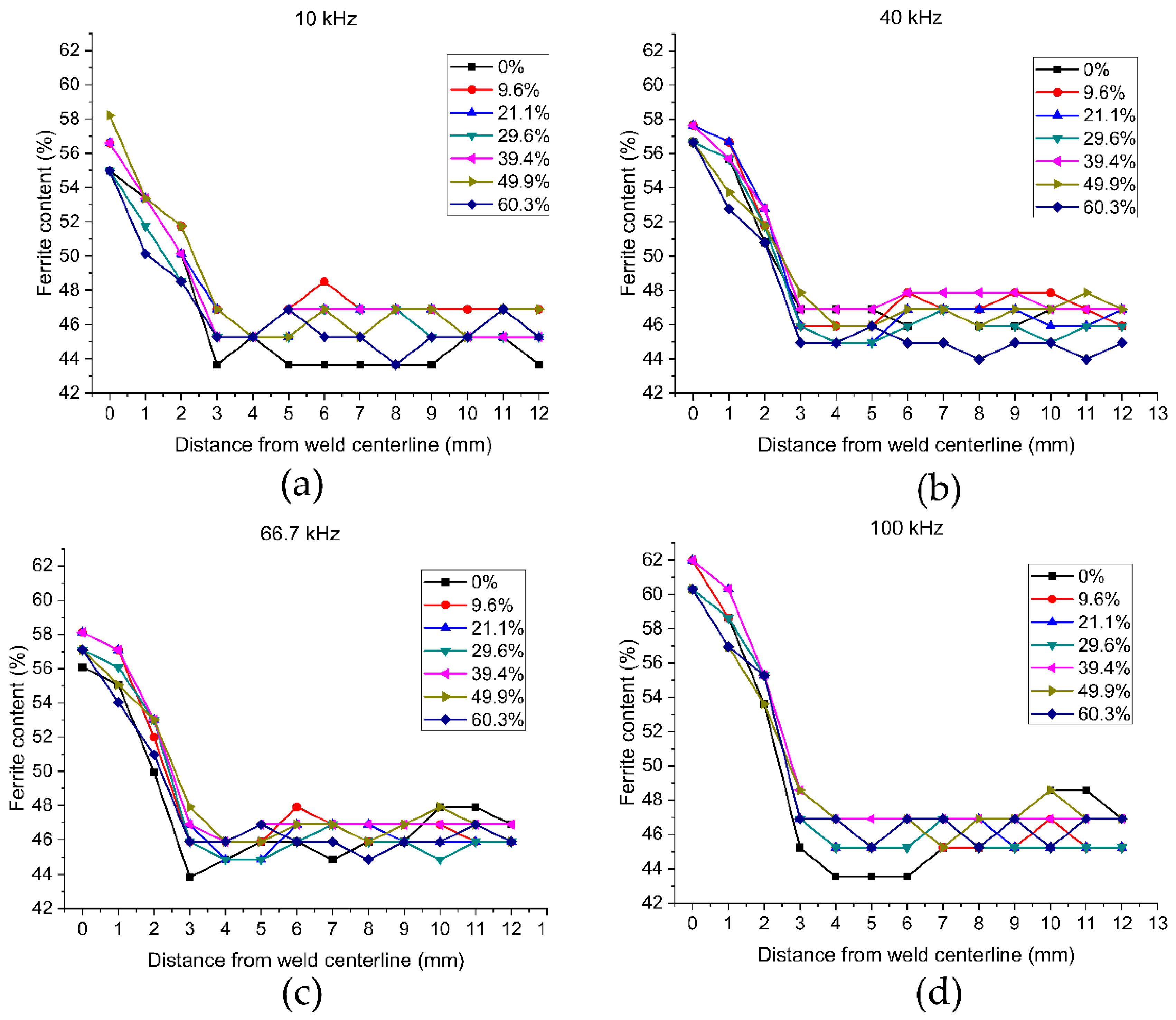
Eddy current tests were performed on the top section of the welded samples in order to analyze the change in ferrite content. Eddy’s current results of the four frequencies used in the tests (10 kHz; 40 kHz; 66.7 kHz; 100 kHz) are reported in Figure 12. A touch coil absolute probe with diameter of 1 mm. The probe was fixed in a holding device which ensured the perpendicular position of the probe with respect to the surface of the sample. The sample was moving under the fixed probe.
In accordance with previous studies [8,9,32,33], it can be seen that the amount of ferrite in the weld zone (~60%) is remarkably higher compared to the base material (46,9%) due to the high cooling rate typical of the laser welding. The precise ferrite content in the HAZ could not be measured because the dimension of the eddy current probe was significantly bigger (~1 mm) than the extension of the zone (~50 µm). However, the tendency of the ferrite content to decrease with increasing distances from the middle of the weld is quite clear for every frequency; the 40 kHz frequency was the most sensitive to the ferrite content variation. High heat input and small spot size of the laser combined with the fast welding process translates in narrow melted region (approximately 0.8 mm according to Figure 2) which limits the width of the HAZ thanks to the base material acting as a heat sink.
4. Conclusions
The main goal of this study was the investigation of cold rolling on the weldability of UNS S32750 duplex stainless steel. The importance of this problem arises from the fact that the cold rolling before the heat treatment can significantly increase the rate and decreases the starting temperature of the ferrite decomposition process. The mentioned phase transformation strongly influences the phase balance and deteriorates the mechanical properties and the corrosion resistance of DSS as well. Therefore, cold rolling prior to the welding process can be considered as an additional technological risk.
Three sets of seven different samples of UNS S32750 hot rolled and annealed with different thickness reduction up to 60.3% were laser welded and investigated by mean of CPT, microhardness and eddy current tests. It has been found that:
- The higher the thickness reduction the lower the CPT for the base material.
- Thickness reduction does not influence the CPT of the welded samples.
- Most of the pits are located in the weld beads due to the unbalanced microstructure (higher ferrite volume fraction).
- The higher the thickness reduction the higher the microhardness on the base material due to strain hardening effects.
- Microhardness of the welded region is not influenced by the prior plastic deformation.
- Prior plastic deformation does not influence the phase balance on the weld beads.
- Higher volume fraction of ferrite (60%) within the joint is responsible for the decrease in CPTs of the welds.
Author Contributions
Conceptualization, I.C., I.M. and L.P.; Data curation, C.G. and B.B.; Formal analysis, C.G. and M.L.; Investigation, C.G., M.L., B.B. and L.P.; Methodology, C.G., L.P. and I.C.; Project administration, L.P., I.C. and I.M.; Supervision, I.C. and I.M.; Validation, L.P., C.G., B.B. and M.L.; Visualization, C.G.; Writing—original draft, C.G., M.L. and B.B.; Writing—review & editing, C.G., I.C., B.B. and I.M.
Conflicts of Interest
The authors declare no conflict of interest.
References
- Alvarez-Armas, I.; Degallaix-Moreuil, S.; Iris Alvarez Armas, S.D.M. Duplex Stainless Steels; Wiley: Hoboken, NJ, USA, 2009; ISBN 978-1-848-21137-7. [Google Scholar]
- Gunn, R.N. Duplex Stainless Steels: Microstructure, Properties and Applications; Woodhead Publishing: Cambridge, UK, 1997; ISBN 9781855733183. [Google Scholar]
- Nilsson, J.O. The physical metallurgy of duplex stainless steels. In Proceedings of the Duplex Stainless Steels 97: 5th World Conference, Maastricht, The Netherlands, 21–23 October 1997; pp. 73–82. [Google Scholar]
- Nilsson, J.O. Super duplex stainless steels. Mater. Sci. Technol. 1992, 8, 685–700. [Google Scholar] [CrossRef]
- Li, S.L.; Wang, Y.L.; Wang, X.T. Effects of long term thermal aging on high temperature tensile deformation behaviours of duplex stainless steels. Mater. High Temp. 2015, 32, 524–529. [Google Scholar] [CrossRef]
- Gennari, C.; Pezzato, L.; Piva, E.; Gobbo, R.; Calliari, I. Influence of small amount and different morphology of secondary phases on impact toughness of UNS S32205 Duplex Stainless Steel. Mater. Sci. Eng. A 2018, 729, 149–156. [Google Scholar] [CrossRef]
- Calliari, I.; Pellizzari, M.; Zanellato, M.; Ramous, E. The phase stability in Cr-Ni and Cr-Mn duplex stainless steels. J. Mater. Sci. 2011, 46, 6916–6924. [Google Scholar] [CrossRef]
- Bolut, M.; Kong, C.Y.; Blackburn, J.; Cashell, K.A.; Hobson, P.R. Yb-fibre laser welding of 6 mm duplex stainless steel 2205. Phys. Proced. 2016, 83, 417–425. [Google Scholar] [CrossRef]
- El-Batahgy, A.-M.; Khourshid, A.-F.; Sharef, T. Effect of Laser Beam Welding Parameters on Microstructure and Properties of Duplex Stainless Steel. Mater. Sci. Appl. 2011, 02, 1443–1451. [Google Scholar] [CrossRef]
- Calliari, I.; Ramous, E.; Rebuffi, G.; Straffelini, G. Investigation of secondary phases effect on 2205 DSS fracture toughness. Metall. Ital. 2008, 100, 5–8. [Google Scholar] [CrossRef]
- Gennari, C.; Breda, M.; Brunelli, K.; Ramous, E.; Calliari, I. Influence of small amount of secondary phases on impact toughness of UNS S32205 and Zeron® 100 Duplex Stainless Steel. In Proceedings of the ESSC and DUPLEX 2017—9th European Stainless Steel Conference—Science and Market and 5th European Duplex Stainless Steel Conference and Exhibition, Bergamo, Italy, 25–27 May 2017. [Google Scholar]
- Breda, M.; Calliari, I.; Ramous, E.; Pizzo, M.; Corain, L.; Straffelini, G. Ductile-to-brittle transition in a Zeron© 100 SDSS in wrought and aged conditions. Mater. Sci. Eng. A 2013, 585, 57–65. [Google Scholar] [CrossRef]
- Chen, T.H.; Weng, K.L.; Yang, J.R. The effect of high-temperature exposure on the microstructural stability and toughness property in a 2205 duplex stainless steel. Mater. Sci. Eng. A 2002, 338, 259–270. [Google Scholar] [CrossRef]
- Breda, M.; Pezzato, L.; Pizzo, M.; Calliari, I. Effect of cold rolling on pitting resistance in duplex stainless steels. La Metall. Ital. 2014, 6, 15–19. [Google Scholar]
- Pezzato, L.; Lago, M.; Brunelli, K.; Breda, M.; Calliari, I. Effect of the Heat Treatment on the Corrosion Resistance of Duplex Stainless Steels. J. Mater. Eng. Perform. 2018, 27, 3859–3868. [Google Scholar] [CrossRef]
- Marques, I.J.; Vicente, A.; de Albuquerque Vicente, A.; Tenório, J.A.S.; de Abreu Santos, T.F. Double Kinetics of Intermetallic Phase Precipitation in UNS S32205 Duplex Stainless Steels Submitted to Isothermal Heat Treatment. Mater. Res. 2017, 20, 1–7. [Google Scholar] [CrossRef]
- Luo, J.; Dong, Y.; Li, L.; Wang, X. Microstructure of 2205 duplex stainless steel joint in submerged arc welding by post weld heat treatment. J. Manuf. Process. 2014, 16, 144–148. [Google Scholar] [CrossRef]
- Nowacki, J.; Rybicki, P.P. The influence of welding heat input on submerged arc welded duplex steel joints imperfections. J. Mater. Process. Technol. 2005, 164–165, 1082–1088. [Google Scholar] [CrossRef]
- Sorrentino, S.; Fersini, M.; Zilli, G. Comparison between submerged arc (SAW) and laser welding applied to duplex stainless steel structures for bridges. Weld. Int. 2008, 60, 487–498. [Google Scholar]
- Taban, E.; Kaluc, E. Welding behaviour of duplex and superduplex stainless steels using laser and plasma arc welding processes. Weld. World 2011, 55, 48–57. [Google Scholar] [CrossRef]
- Bharathi, R.S.; Shanmugam, N.S.; Kannan, R.M.; Vendan, S.A. Studies on the Parametric Effects of Plasma Arc Welding of 2205 Duplex Stainless Steel. High Temp. Mater. Process. 2018, 37, 219–232. [Google Scholar] [CrossRef]
- Šimeková, B.; Kovaříková, I.; Ulrich, K. Microstructure and Properties of Plasma Arc Welding with Depth Penetration Keyhole SAF 2205 Duplex Stainless Steel. Adv. Mater. Res. 2013, 664, 578–583. [Google Scholar] [CrossRef]
- Eghlimi, A.; Shamanian, M.; Raeissi, K. Effect of current type on microstructure and corrosion resistance of super duplex stainless steel claddings produced by the gas tungsten arc welding process. Surf. Coat. Technol. 2014, 244, 45–51. [Google Scholar] [CrossRef]
- Neissi, R.; Shamanian, M.; Hajihashemi, M. The Effect of Constant and Pulsed Current Gas Tungsten Arc Welding on Joint Properties of 2205 Duplex Stainless Steel to 316L Austenitic Stainless Steel. J. Mater. Eng. Perform. 2016, 25, 2017–2028. [Google Scholar] [CrossRef]
- Mourad, A.-H.I.; Khourshid, A.; Sharef, T. Gas tungsten arc and laser beam welding processes effects on duplex stainless steel 2205 properties. Mater. Sci. Eng. A 2012, 549, 105–113. [Google Scholar] [CrossRef]
- Chen, W.; Wang, J.; Li, J.; Zheng, Y.; Li, H.; Liu, Y.; Han, P. Effect of the Rotation Speed during Friction Stir Welding on the Microstructure and Corrosion Resistance of SAF 2707 Hyper Duplex Stainless Steel. Steel Res. Int. 2018, 89. [Google Scholar] [CrossRef]
- de Abreu Santos, T.F.; Torres, E.A.; Ramirez, A.J. Friction stir welding of duplex stainless steels. Weld. Int. 2018, 32, 103–111. [Google Scholar] [CrossRef]
- Saeid, T.; Abdollah-zadeh, A.; Assadi, H.; Malek Ghaini, F. Effect of friction stir welding speed on the microstructure and mechanical properties of a duplex stainless steel. Mater. Sci. Eng. A 2008, 496, 262–268. [Google Scholar] [CrossRef]
- Keskitalo, M.; Mäntyjärvi, K.; Sundqvist, J.; Powell, J.; Kaplan, A.F.H. Laser welding of duplex stainless steel with nitrogen as shielding gas. J. Mater. Process. Technol. 2015, 216, 381–384. [Google Scholar] [CrossRef]
- de Lima, M.S.F.; Carvalh, S.M.; Teleginski, V.; Pariona, M. Mechanical and Corrosion Properties of a Duplex Steel Welded using Micro-Arc or Laser-2015. Mater. Res. 2015, 18, 723–731. [Google Scholar] [CrossRef]
- Quiroz, V.; Gumenyuk, A.; Rethmeier, M. Laser beam weldability of high-manganese austenitic and duplex stainless steel sheets. Weld. World 2012, 56, 9–20. [Google Scholar] [CrossRef]
- Saravanan, S.; Raghukandan, K.; Sivagurumanikandan, N. Pulsed Nd: YAG laser welding and subsequent post-weld heat treatment on super duplex stainless steel. J. Manuf. Process. 2017, 25, 284–289. [Google Scholar] [CrossRef]
- Sivakumar, G.; Saravanan, S.; Raghukandan, K. Investigation of microstructure and mechanical properties of Nd:YAG laser welded lean duplex stainless steel joints. Optik (Stuttg.) 2017, 131, 1–10. [Google Scholar] [CrossRef]
- Arabi, S.H.; Pouranvari, M.; Movahedi, M. Pathways to improve the austenite–ferrite phase balance during resistance spot welding of duplex stainless steels. Sci. Technol. Weld. Join. 2018, 24, 1–8. [Google Scholar] [CrossRef]
- Yasuda, K.; Gunn, R.N.; Gooch, T.G. Prediction of austenite phase fraction in duplex stainless steel weld metals. Q. J. Jpn. Weld. Soc. 2002, 20, 68–77. [Google Scholar] [CrossRef]
- Varbai, B.; Pickle, T.; Májlinger, K. Development and comparison of quantitative phase analysis for duplex stainless steel weld. Period. Polytech. Mech. Eng. 2018, 62, 247–253. [Google Scholar] [CrossRef]
- Baughn, K.E.; Ahmed, N.U.; Jarvis, B.L.; Viano, D.M. Tailoring the phase balance during laser and GTA keyhole welding of SAF 2205 duplex stainless steel. In Proceedings of the 6th International Conference of Trends in Welding Research, Pine Mountain, GA, USA, 15–19 April 2002; pp. 11–16. [Google Scholar]
- Meng, W.; Li, Z.; Huang, J.; Wu, Y.; Chen, J.; Katayama, S. The influence of various factors on the geometric profile of laser lap welded T-joints. Int. J. Adv. Manuf. Technol. 2014, 74, 1625–1636. [Google Scholar] [CrossRef]
- Mirakhorli, F.; Malek Ghaini, F.; Torkamany, M.J. Development of weld metal microstructures in pulsed laser welding of duplex stainless steel. J. Mater. Eng. Perform. 2012, 21, 2173–2176. [Google Scholar] [CrossRef]
- Menezes, A.J.W.; Abreu, H.; Kundu, S.; Bhadeshia, H.K.D.H.; Kelly, P.M. Crystallography of Widmanstätten austenite in duplex stainless steel weld metal. Sci. Technol. Weld. Join. 2009, 14, 4–10. [Google Scholar] [CrossRef] [Green Version]
- Ohmori, Y.; Nakai, K.; Ohtsubo, H.; Isshiki, Y. Mechanism of Widmanstaetten Austenite Formation in a .DELTA./.GAMMA. Duplex Phase Stainless Steel. ISIJ Int. 1995, 35, 969–975. [Google Scholar] [CrossRef]
- Serre, I.; Salazar, D.; Vogt, J.B. Atomic force microscopy investigation of surface relief in individual phases of deformed duplex stainless steel. Mater. Sci. Eng. A 2008, 492, 428–433. [Google Scholar] [CrossRef]
- Amigó, V.; Bonache, V.; Teruel, L.; Vicente, A. Mechanical properties of duplex stainless steel laser joints. Weld. Int. 2006, 20, 361–366. [Google Scholar] [CrossRef] [Green Version]
- Köse, C.; Kaçar, R. Mechanical Properties of Laser Welded 2205 Duplex Stainless Steel. Mater. Test. 2014, 56, 779–785. [Google Scholar] [CrossRef]
- Elhoud, A.M.; Renton, N.C.; Deans, W.F. The effect of manufacturing variables on the corrosion resistance of a super duplex stainless steel. Int. J. Adv. Manuf. Technol. 2011, 52, 451–461. [Google Scholar] [CrossRef]
- Matting, A.; Koch, H.; Dorn, L. Einfluß des Elektronenstrahl- und Schutzgasschweißens auf das Korrosionsverhalten von X5 CrNiMo 18 10. Mater. Corros. 1970, 21, 94–97. [Google Scholar] [CrossRef]
- Elayaperumal, K.; De, P.K.; Balachandra, J. Passivity of Type 304 Stainless Steel-Effect of Plastic Deformation. Corrosion 1972, 28, 269–273. [Google Scholar] [CrossRef]
- Phadnis, S.V.; Satpati, A.K.; Muthe, K.P.; Vyas, J.C.; Sundaresan, R.I. Comparison of rolled and heat treated SS304 in chloride solution using electrochemical and XPS techniques. Corros. Sci. 2003, 45, 2467–2483. [Google Scholar] [CrossRef]
- Navaï, F. Effects of tensile and compressive stresses on the passive layers formed on a type 302 stainless steel in a normal sulphuric acid bath. J. Mater. Sci. 1995, 30, 1166–1172. [Google Scholar] [CrossRef]
- Greene, N.D.; Saltzman, G.A. Effect of Plastic Deformation On the Corrosion of Iron and Steel. Corrosion 1964, 20, 293t–298t. [Google Scholar] [CrossRef]
- Serna, M.M.; Jesus, E.R.B.; Galego, E.; Martinez, L.G.; Corrêa, H.P.S.; Rossi, J.L. An Overview of the Microstructures Present in High-Speed Steel -Carbides Crystallography. Mater. Sci. Forum 2006, 530–531, 48–52. [Google Scholar] [CrossRef]
- Chiu, P.K.; Wang, S.H.; Yang, J.R.; Weng, K.L.; Fang, J. The effect of strain ratio on morphology of dislocation in low cycle fatigued SAF 2205 DSS. Mater. Chem. Phys. 2006, 98, 103–110. [Google Scholar] [CrossRef]
Figure 1.
Microstructure of as received UNS S32750 bar.
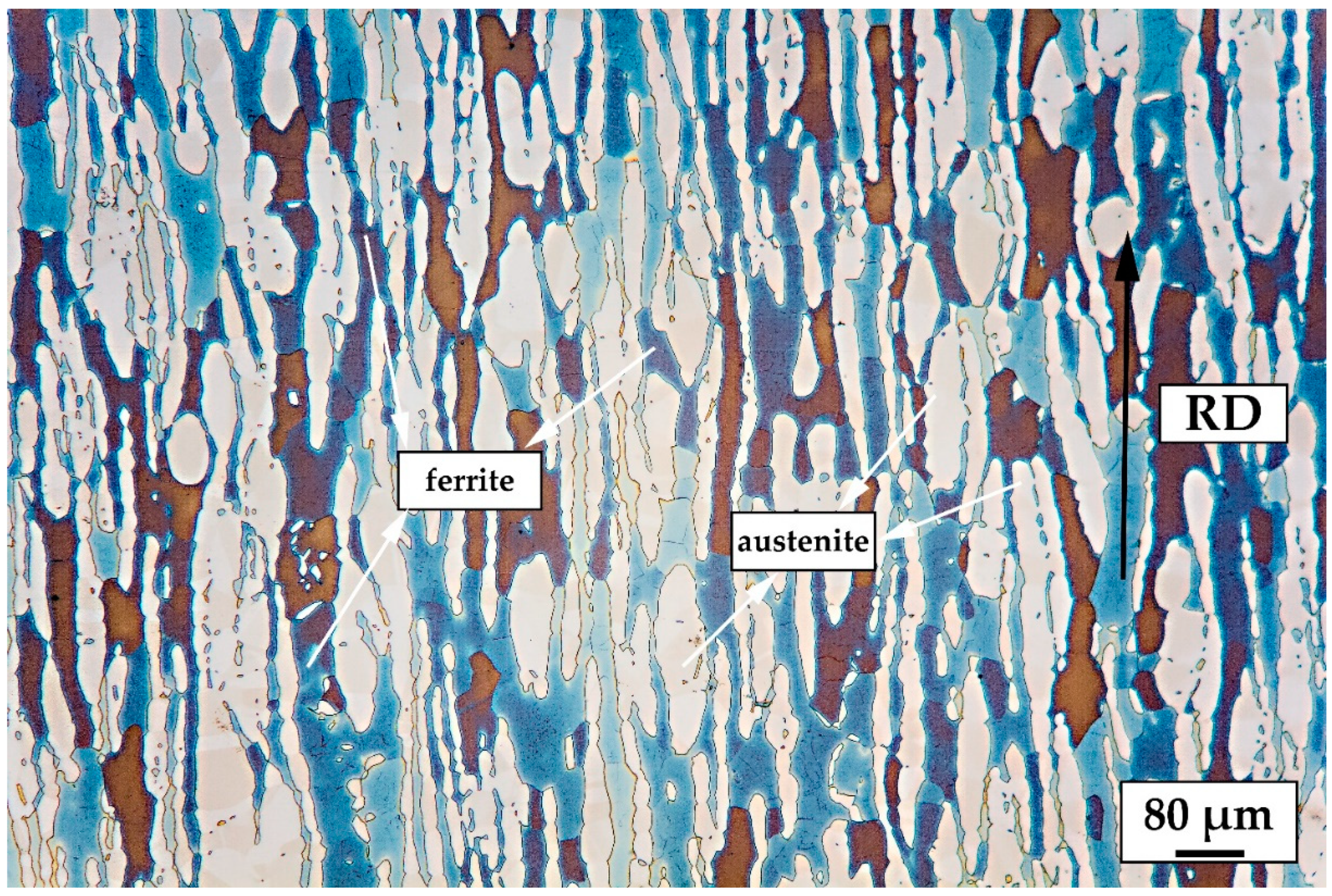
Figure 2.
Overview of weld bead of the undeformed sample (electrolytic etching at 20 V with 20% NaOH).
Figure 2.
Overview of weld bead of the undeformed sample (electrolytic etching at 20 V with 20% NaOH).
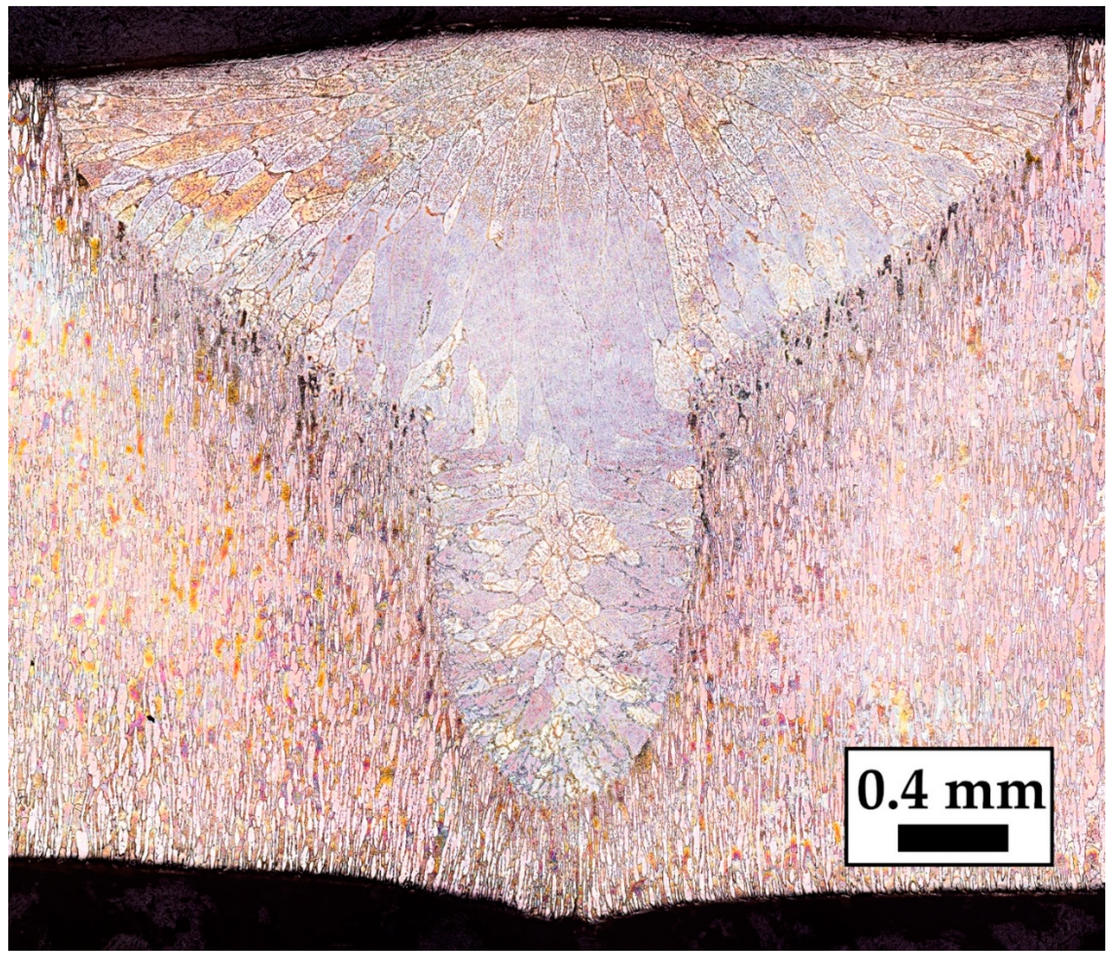
Figure 3.
Heat Affected Zone (HAZ) of the sample deformed at 29.6%.
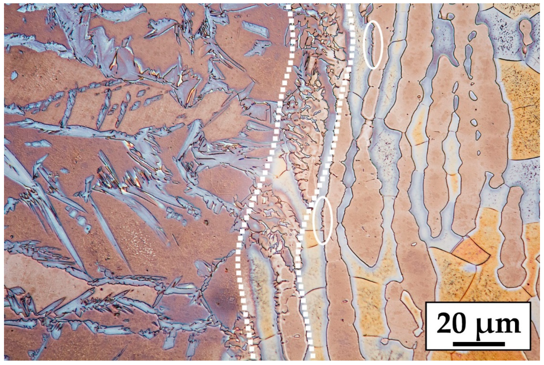
Figure 4.
Back-scattered electron micrograph of the HAZ region (center), the weld bead (left) and the base metal (right).
Figure 4.
Back-scattered electron micrograph of the HAZ region (center), the weld bead (left) and the base metal (right).
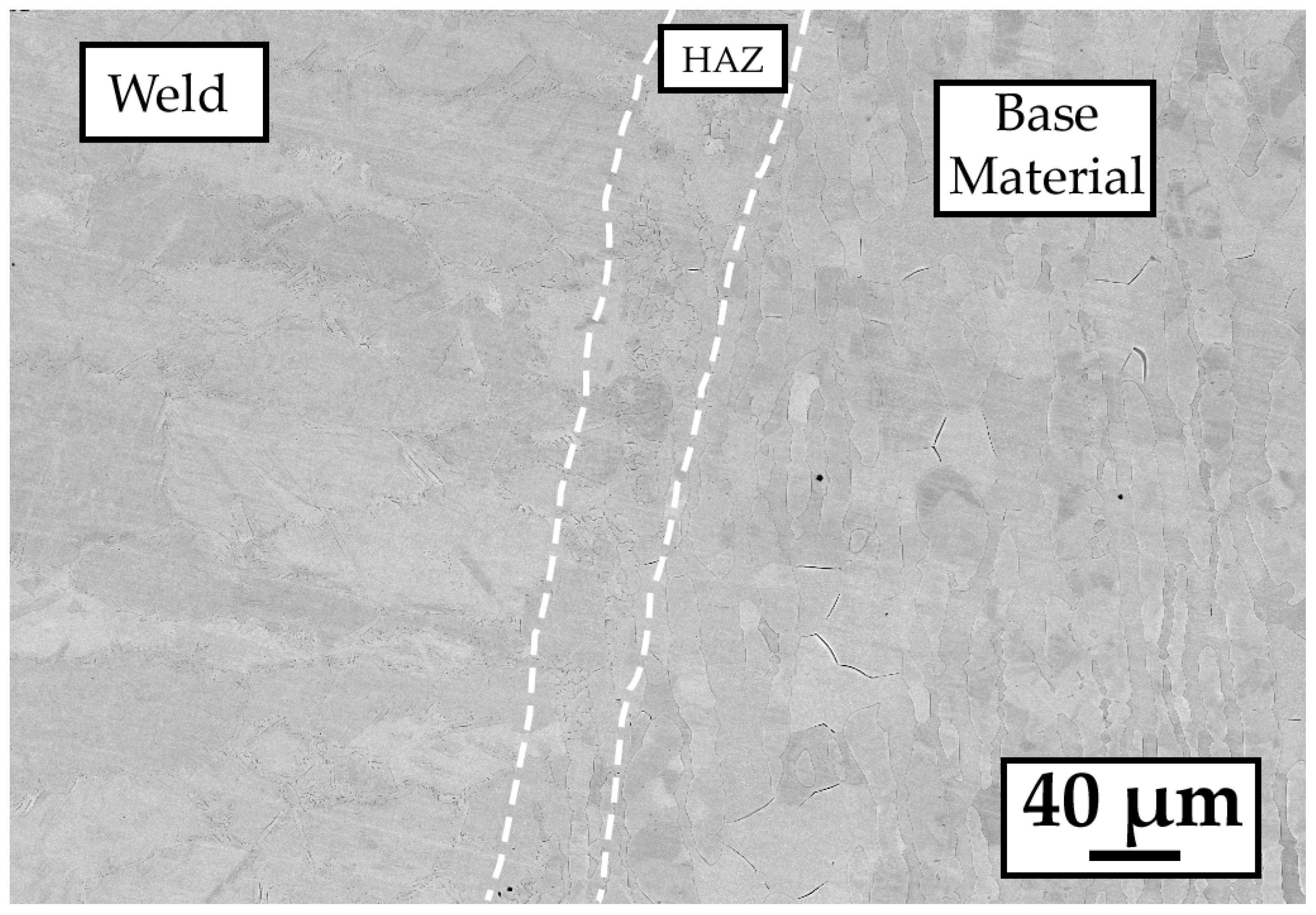
Figure 5.
Microstructure of the welded zone showing austenite (light phase) and ferrite (brown matrix).
Figure 5.
Microstructure of the welded zone showing austenite (light phase) and ferrite (brown matrix).

Figure 6.
Deformation bands inside austenite and ferrite due to thickness reduction. (a) 29.6% thickness reduction, (b) 39.9% thickness reduction, (c,d) 49.9% thickness reduction, and (e,f) 60.3% thickness reduction.
Figure 6.
Deformation bands inside austenite and ferrite due to thickness reduction. (a) 29.6% thickness reduction, (b) 39.9% thickness reduction, (c,d) 49.9% thickness reduction, and (e,f) 60.3% thickness reduction.
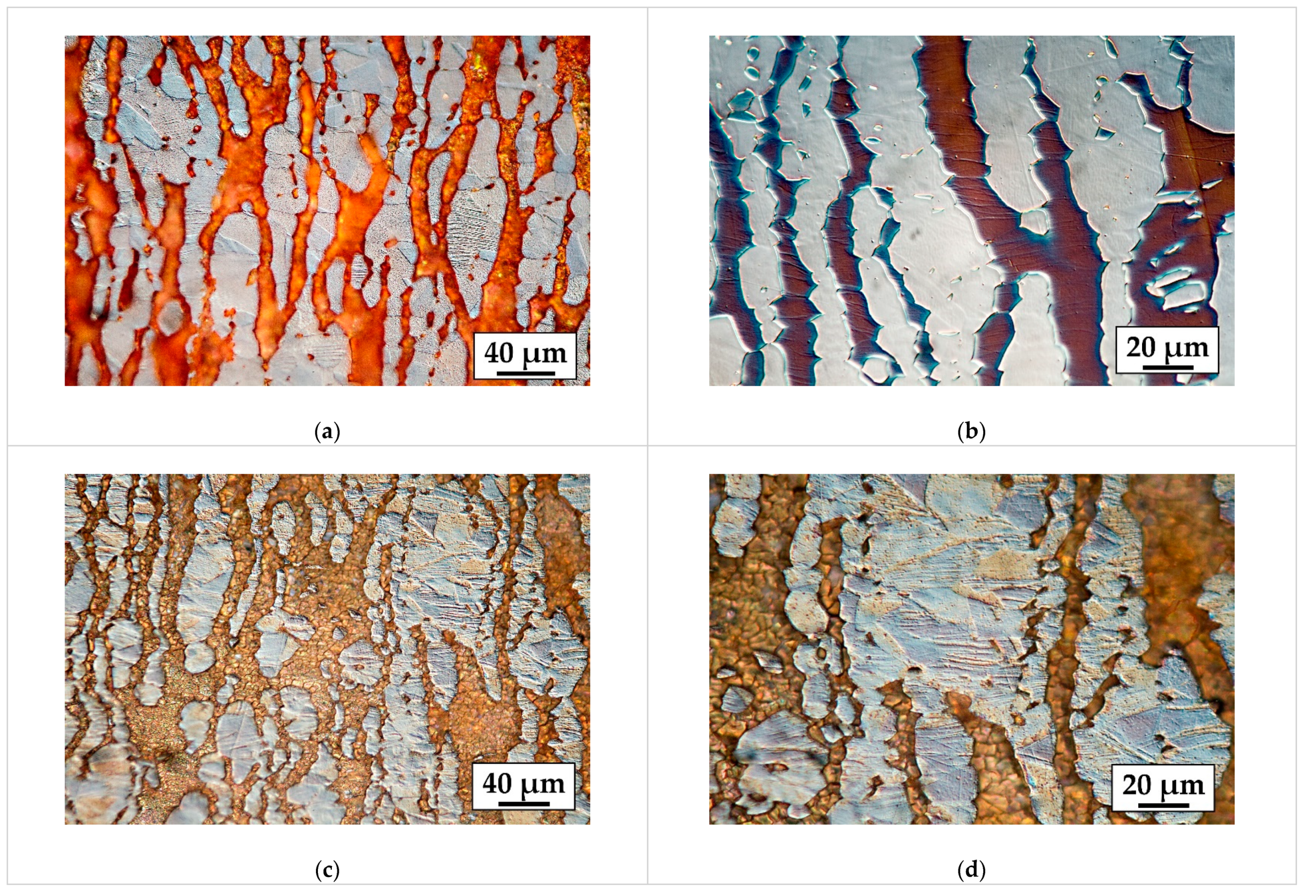
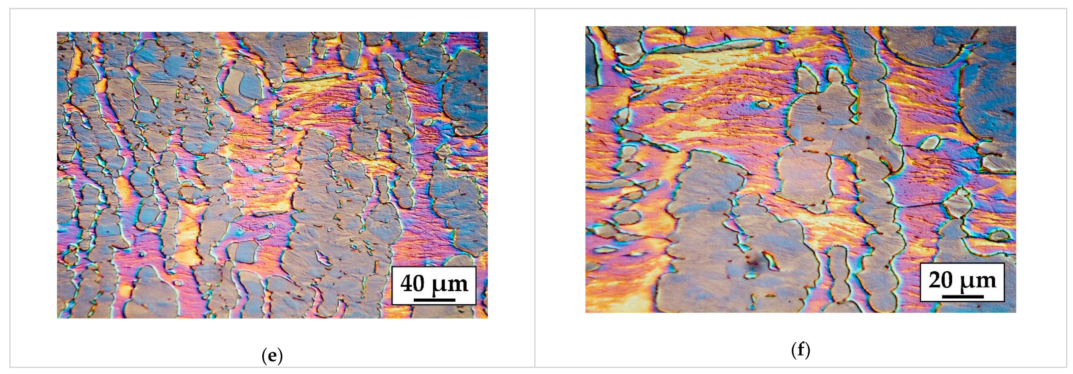
Figure 7.
Evolution of hardness with respect to thickness reduction for the welds, the HAZ and the base material.
Figure 7.
Evolution of hardness with respect to thickness reduction for the welds, the HAZ and the base material.

Figure 8.
Close-up of the region of interest of the critical pitting temperature (CPT) curves of welded sheet metal.
Figure 8.
Close-up of the region of interest of the critical pitting temperature (CPT) curves of welded sheet metal.
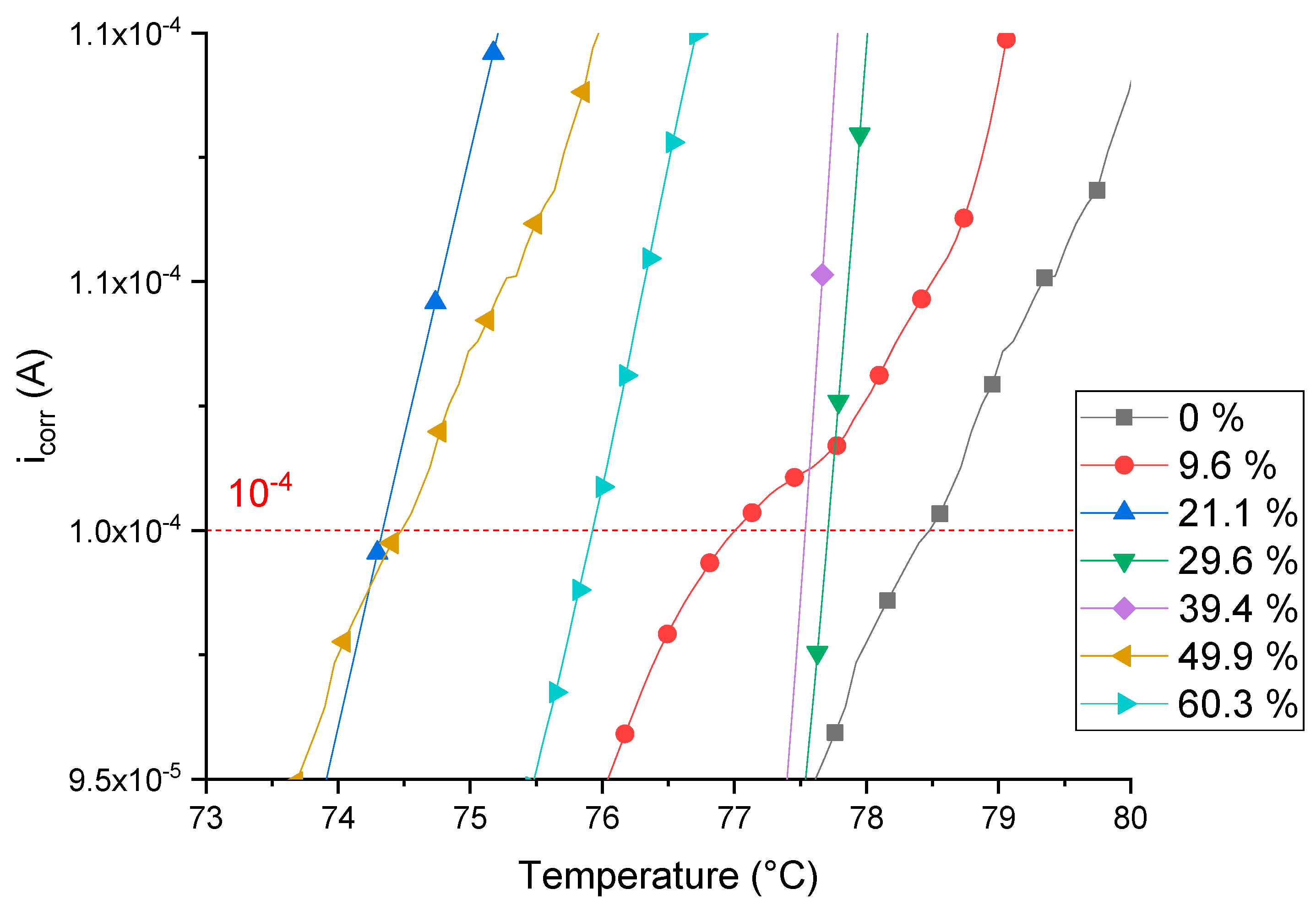
Figure 9.
CPT curves of unwelded sheet metal.
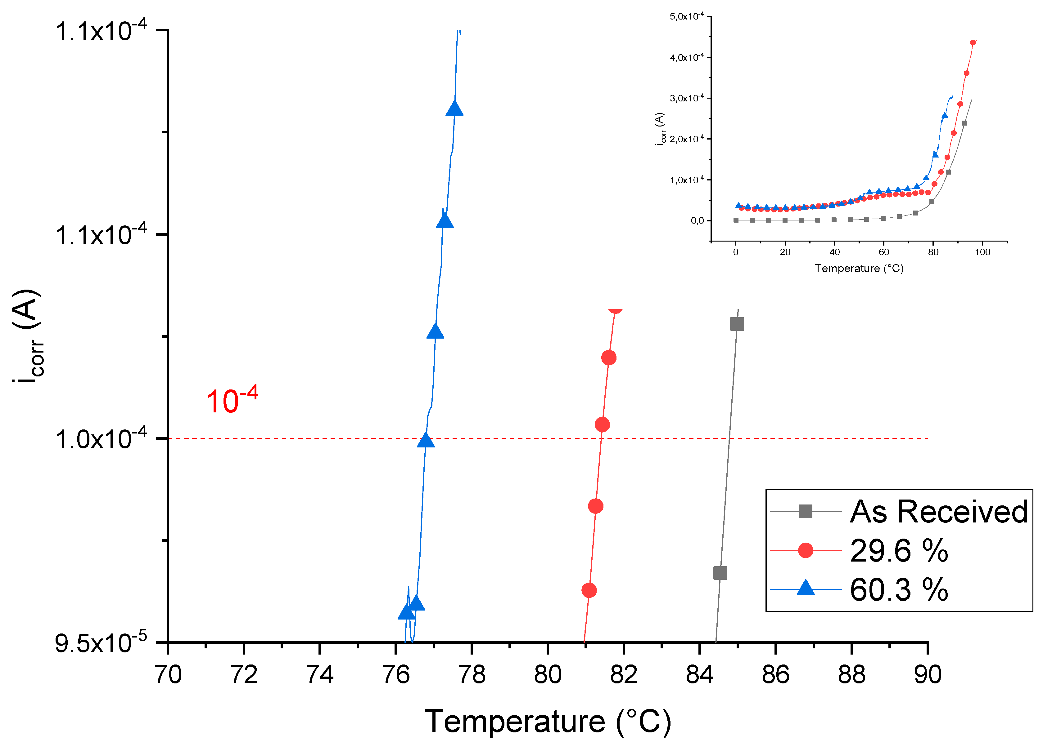
Figure 10.
CPT trend of welded and unwelded sheets. For comparison is also reported the CPT of a bar of UNS S32750.
Figure 10.
CPT trend of welded and unwelded sheets. For comparison is also reported the CPT of a bar of UNS S32750.
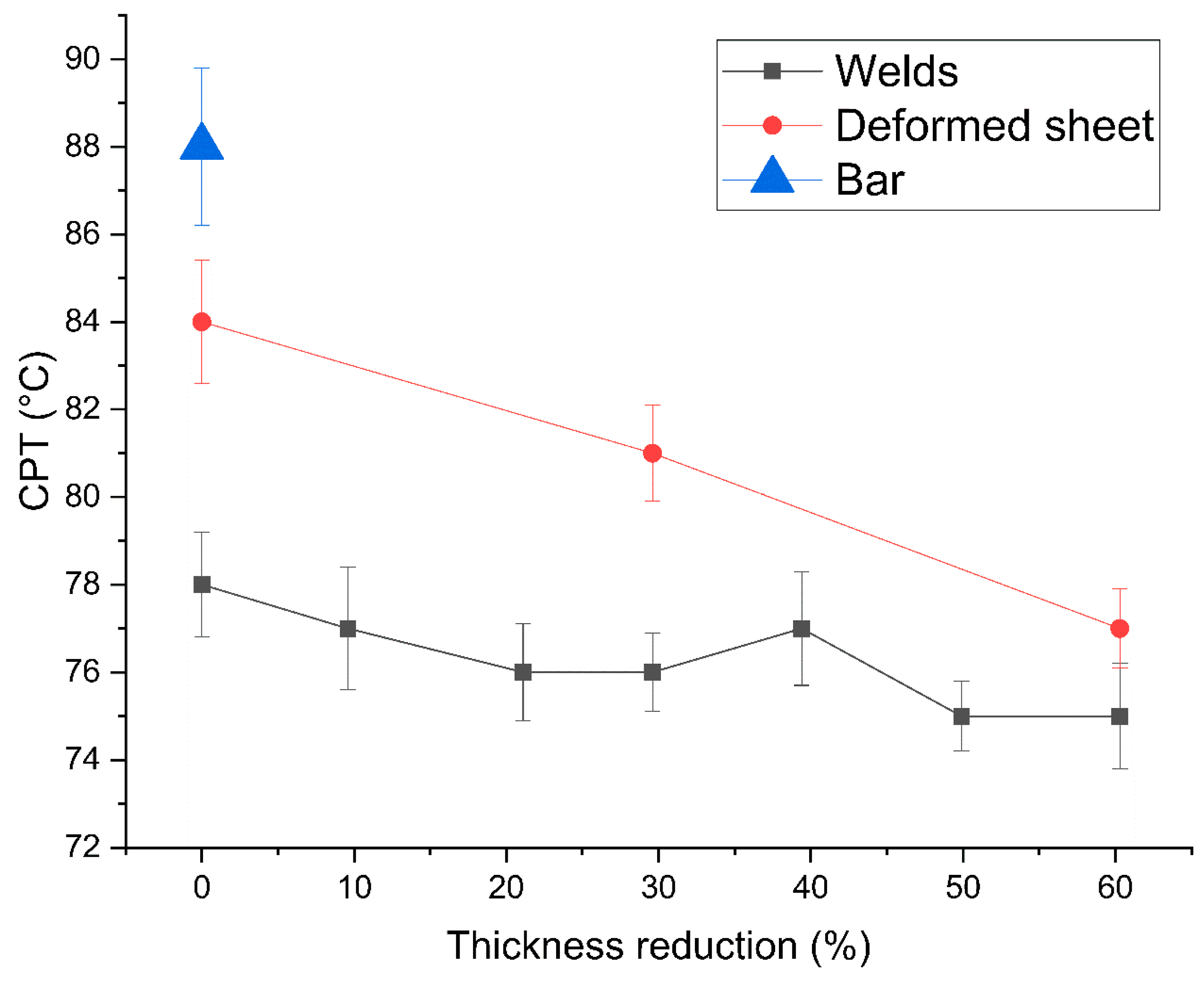
Figure 11.
Pits location on the welded sample after CPT tests: (a,b) undeformed; (c,d) 9.6% thickness reduction; (e,f) 21.1% thickness reduction; (g,h) 29.6% thickness reduction; (i,j) 39.4% thickness reduction; (k,l) 49.9% thickness reduction; and (m,n) 60.3% thickness reduction. Right column images are higher magnification of the highlighted area of the pictures on the left column.
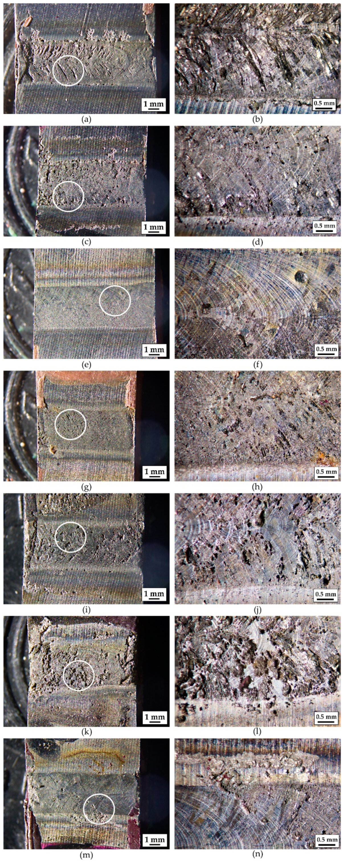
Figure 12.
Evolution of the volume fraction of ferrite with respect to the distance from the weld centerline.
Figure 12.
Evolution of the volume fraction of ferrite with respect to the distance from the weld centerline.

Table 1.
Chemical composition of UNS S32750.
| Element | C | Mn | P | S | Si | Cu | Ni | Cr | Mo | N |
|---|---|---|---|---|---|---|---|---|---|---|
| % | 0.021 | 0.822 | 0.0231 | 0.0004 | 0.313 | 0.178 | 6.592 | 24.792 | 3.705 | 0.2644 |
Table 2.
Laser welding parameters.
| Parameters | Value |
|---|---|
| Average power | 1400 W |
| Welding speed | 450 mm/min |
| Defocusing distance | 0 mm |
| Spot Diameter | 0.2 mm |
| Shielding gas flow rate | 20 L/min |
Table 3.
CPT of the welded sheet metal.
| Thickness Reduction % | CPT [°C] |
|---|---|
| 0 | 78 ± 1.2 |
| 9.6 | 77 ± 1.4 |
| 21.1 | 76 ± 1.1 |
| 29.6 | 76 ± 0.9 |
| 39.4 | 77 ± 1.3 |
| 49.9 | 75 ± 0.8 |
| 60.3 | 75 ± 1.2 |
Table 4.
CPT of the unwelded sheet metal. For comparison is also reported the CPT of a bar of UNS S32750.
Table 4.
CPT of the unwelded sheet metal. For comparison is also reported the CPT of a bar of UNS S32750.
| Thickness Reduction % | CPT [°C] |
|---|---|
| 0 | 84 ± 1.4 |
| 29.6 | 81 ± 1.1 |
| 60.3 | 77 ± 0.9 |
| Not rolled (bar) | 88 ± 1.8 |
© 2018 by the authors. Licensee MDPI, Basel, Switzerland. This article is an open access article distributed under the terms and conditions of the Creative Commons Attribution (CC BY) license (http://creativecommons.org/licenses/by/4.0/).
Share and Cite
MDPI and ACS Style
Gennari, C.; Lago, M.; Bögre, B.; Meszaros, I.; Calliari, I.; Pezzato, L. Microstructural and Corrosion Properties of Cold Rolled Laser Welded UNS S32750 Duplex Stainless Steel. Metals 2018, 8, 1074. https://doi.org/10.3390/met8121074
AMA Style
Gennari C, Lago M, Bögre B, Meszaros I, Calliari I, Pezzato L. Microstructural and Corrosion Properties of Cold Rolled Laser Welded UNS S32750 Duplex Stainless Steel. Metals. 2018; 8(12):1074. https://doi.org/10.3390/met8121074
Chicago/Turabian StyleGennari, Claudio, Mattia Lago, Balint Bögre, Istvan Meszaros, Irene Calliari, and Luca Pezzato. 2018. "Microstructural and Corrosion Properties of Cold Rolled Laser Welded UNS S32750 Duplex Stainless Steel" Metals 8, no. 12: 1074. https://doi.org/10.3390/met8121074
Note that from the first issue of 2016, this journal uses article numbers instead of page numbers. See further details here.