Sliding Wear Behavior of Friction Couples Primarily Selected for Corrosion Resistance: Iron Boride/Iron Boride and Iron Boride/Yttria-Stabilized Zirconia


4MAT Department, Université libre de Bruxelles (ULB), 50 Av. FD Roosevelt, CP194/3, 1050 Brussels, Belgium
*
Author to whom correspondence should be addressed.
Metals 2018, 8(12), 1071; https://doi.org/10.3390/met8121071
Submission received: 14 November 2018
/
Revised: 12 December 2018
/
Accepted: 14 December 2018
/
Published: 16 December 2018
(This article belongs to the Special Issue Post-Processing Improvements for Mechanical, Microstructure, and Surface Properties of Steel)
Abstract
:Wear mitigation in a sliding couple is challenging if wear has to be minimized on both surfaces. In this paper, ball-on-disk testing is performed on sliding couples where both surfaces (ball and disk) are treated for wear resistance. Studied materials are pack borided H13 tool steel (ASTM A681), pack borided AISI 420 stainless steel (ASTM A276) and plasma sprayed yttria-stabilized zirconia (YSZ). Borided H13 steel exhibits a single phase Fe2B layer, while AISI 420 has a double phase layer, with FeB on the outer surface. Both FeB/Fe2B and FeB/YSZ couples generate three-body abrasion. In the latter case, mass transfer occurs from the ball to the disk as well. Friction coefficient is ~0.6 for the AISI 420/Fe2B and FeB/Fe2B sliding pairs, with less vibration on the latter and wear rates close to 10−3 mm³·(N·m)−1 for both the ball and the disk. In comparison, the FeB/YSZ pair has a friction coefficient of ~0.65, a similar total mass loss, but a much higher wear rate for YSZ than for FeB.
1. Introduction
The selection of surface treatments for steel exposed simultaneously or separately to sliding wear and corrosive conditions is a complex problem [1], especially if both sliding parts must be designed for a high lifetime. In this work, we consider a fixed slide on which moves another component, just above a bath of molten aluminum, in a foundry device. The slide is not immersed into the metal but suffers from hard to avoid projections from the bath, which is likely to generate physical corrosion if it is made of plain steel. The system is designed so as to keep the slide temperature close to room temperature, with only temporary thermal variations. The counterpart faces similar conditions. Both components should also be wear resistant and slide without sticking. They should also have some resistance to molten metal. Two surface modifications are considered as potential candidates.
The first candidate is steel boriding. In pack boriding, steel parts are immersed into a solid medium consisting of a source of boron like B4C and an activator like KBF4, NaBF4 or NH4BF4. The steel and the reactants are then heat treated, typically at 900 °C, to diffuse boron and precipitate FeB and/or Fe2B, depending on the substrate and the treatment conditions [2,3]. The mechanism of boriding has been described by Spence et al. in the case of KBF4 as activator. To limit the amount of brittle FeB, a filler like SiC is added in the bed, so as to dilute boron in contact with the steel during treatment [4]. Boron diffusion is described in details in the case of non-alloyed iron, with diffusion coefficient values and detailed chemical characterization [5,6]. The influence of alloying elements on the obtained layers (thickness and type) is well known ([2], p. 32 and 37) and the kinetics of boriding are described for various alloys [7,8], including Cr-rich hot work tool steel [9,10] used in the foundry applications, and stainless steels [11]. Alternative processes are also reported [12,13,14].
Thanks to a hardness up to 2000 HV (Vickers hardness), boriding can be a solution against abrasive or adhesive wear [2,15,16,17], even at temperature higher than room temperature: a high hardness can be expected up to 650 °C [18]. The advantage of borided steel on plain tool steel is maintained at 500 °C in wear tests [19]. It reduces the friction coefficient against steel [16,20] and is appropriate for applications like gears [21]. These tribological features combine with corrosion resistance in saline solutions [22], acids [18,23], and in molten metal [24,25].
In the case of borided high chromium steel, the properties remain similar: Dybkov et al. even found a strong increase of the abrasive wear resistance when the chromium content increases in the substrate [26]. The boriding layers are also appropriate for cyclic oxidation conditions [27]. They demonstrated significant increase of the resistance to the corrosion by molten aluminum, compared to untreated stainless steel [28] and to hot work tool steel [29,30,31]. Thanks to these two latest properties, they constitute a potential protection treatment for steel in the foundry industry; However, they still suffer from limited thermal fatigue resistance [32].
In present work, where occasional non-tribological solicitations occur, both counter-parts need to be surface treated. Tribological tests in which iron borides are tested against themselves are rarely reported. According to Habig, the sliding wear of borided steel against itself can be attributed to tribo-oxidation, in ambient atmosphere. Under vacuum, adhesive wear is reported [33,34]. Garcia-Bustos et al. performed four-ball tests on borided steel balls contacting each other and reported a strong influence of the load on the friction coefficient in non lubricated conditions, from ~0.55 at 49 N to 0.35 at 147 N, suggesting a lubricating effect at high loads [35].
An alternative to solely “boride” both surfaces is to select another rather inert counter-body than iron borides. Data already exist for the couple borided steel/alumina [36,37]. In friction tests, friction coefficient starts from 0.15–0.2, but increases due to the formation of superficial oxides, to reach the same value as untreated steel (0.5–0.7) [36]. Dynamic friction coefficient against silicon nitride decreases from ~0.6 to ~0.45, while wear rate is multiplied by ~2 during such tests [38]. Against diamond like carbon (DLC) coatings, the friction coefficient is reduced to ~0.1 and wear rate is lower than 10−8 mm³·(N·m)−1 [39].
The second candidate is yttria-stabilized zirconia thermal spray coating (YSZ). It is usually used as a thermal barrier, thanks to its low thermal conductivity and its excellent resistance to oxidation. However, YSZ has already been suggested for applications in molten metal [40] and has proved some resistance to molten aluminum [41]. Although YSZ coating is not primarily used for tribological applications, the dense material exhibits a hardness of 1200–1280 HV [42,43] and has been proposed yet for specific wear problems [42,44,45,46,47]. The friction behavior of zirconia against iron borides is unknown.
The main goal of this paper is therefore to investigate the tribological behavior of borided or YSZ-coated hot work tool steel against a borided counter-body, with special focus on the wear rate of both materials. The two different borides are obtained by the pack boriding of martensitic stainless steel and H13 hot work tool steel, respectively. Other combinations that include untreated steel are used as benchmarks. In this work, YSZ is deposited on top of the boriding layer. There exist very limited examples of such multilayer treatments with boriding in the literature, in the case of wear problems [48].
2. Materials and Methods
The selected wear test is the classical ball-on-disk test [49,50,51]. For disks, substrates consisted of annealed H13 (ASTM A681) hot work tool steel bars, normalized 1 h at 850 °C; they were either untreated, or treated by pack boriding in a commercial solid product consisting of B4C, KBF4 and SiC (5 h, 1173 K). Prior to the treatment, the polished samples were degreased using acetone and ethanol, and dried. The treatment was performed in a closed metallic box (~35 cm × 20 cm × 10 cm) completely filled with the mixture. Reacting surfaces were distanced a minimum of 4 cm from each other, to guarantee the availability of boron. Temperature inside the box was controlled using a thermocouple.
In order to study the influence of the YSZ layer, additional samples were pack borided, then sand blasted and plasma sprayed, so as to obtain a NiCrAlY bond coat and an YSZ coating, following the same protocol as in [52]. NiCrAlY and YSZ powders were Praxair Ni-164-2 and Amdry 6643, respectively, dried at 60 °C before deposition in a Plasma Technik AG chamber, by sweeping the samples with the spray nozzle.
For the pins, AISI 420 steel balls (ASTM A276) of nominal composition Cr 12–14%, C 0.3–0.4% were borided with the same procedure as H13.
Before selecting the materials, the device (in fact, an ancillary system used in molding operations) should be designed so as to avoid simultaneous and continuous conditions of physical corrosion and sliding. Therefore, the sliding zone is positioned outside the molten bath. Materials can then be compared in less aggressive conditions. Since no lubricant can be used, the wear test was performed in dry conditions. The conditions are 298 K, an applied load of 5 N, a speed of 2 cm/s and a duration of 20 min (total length: 23 m). Tangential force was measured and recorded via a specific computer program. After the tests, the samples were cleaned by compressed air.
Materials and wear tracks were characterized using scanning electron microscope in secondary or backscattered electrons mode (SEM, FEI, Quanta 3D, Hillsboro, OR, USA) and energy-dispersive X-ray spectroscopy (EDX). Backscattered electrons were selected when elemental contrast was needed. Cross-sections on chromium rich AISI 420 steel were obtained after polishing with diamond paste and etching with Vilella’s reactant [53]. On H13 steel, nital was used instead.
Based on these cross-sections, Vickers microhardness was measured on each material, with a load of 0.98 N (100 g) or 1.96 N (200 g), depending on the area available for the indentation. The surface roughness of the disks was controlled using a Perthometer C5D® (Feinprüf, Göttingen, Germany).
For phase identification, X-ray diffraction (XRD) analyses were performed using a Brücker D5000 diffractometer® (Bruker, Karlsruhe, Germany), with the Kα ray of copper, the θ/2θ mode and a database of inorganic compounds. Acquisition speed is 1.2 s per step of 0.02°.
For the ball, wear rate “K” in Archard’s law was calculated from the volume of removed material, measured by SEM. For the disk, and due to low depth of the track, K was calculated from mass variations, using a balance precise to 0.1 mg and the density of the worn materials (H13, Fe2B or YSZ), so as to make comparisons with the ball possible. These are lower bound values, since some mass transfer from the ball to the disk is sometimes observed.
3. Results
3.1. Phase Identification in the Powder after Boriding
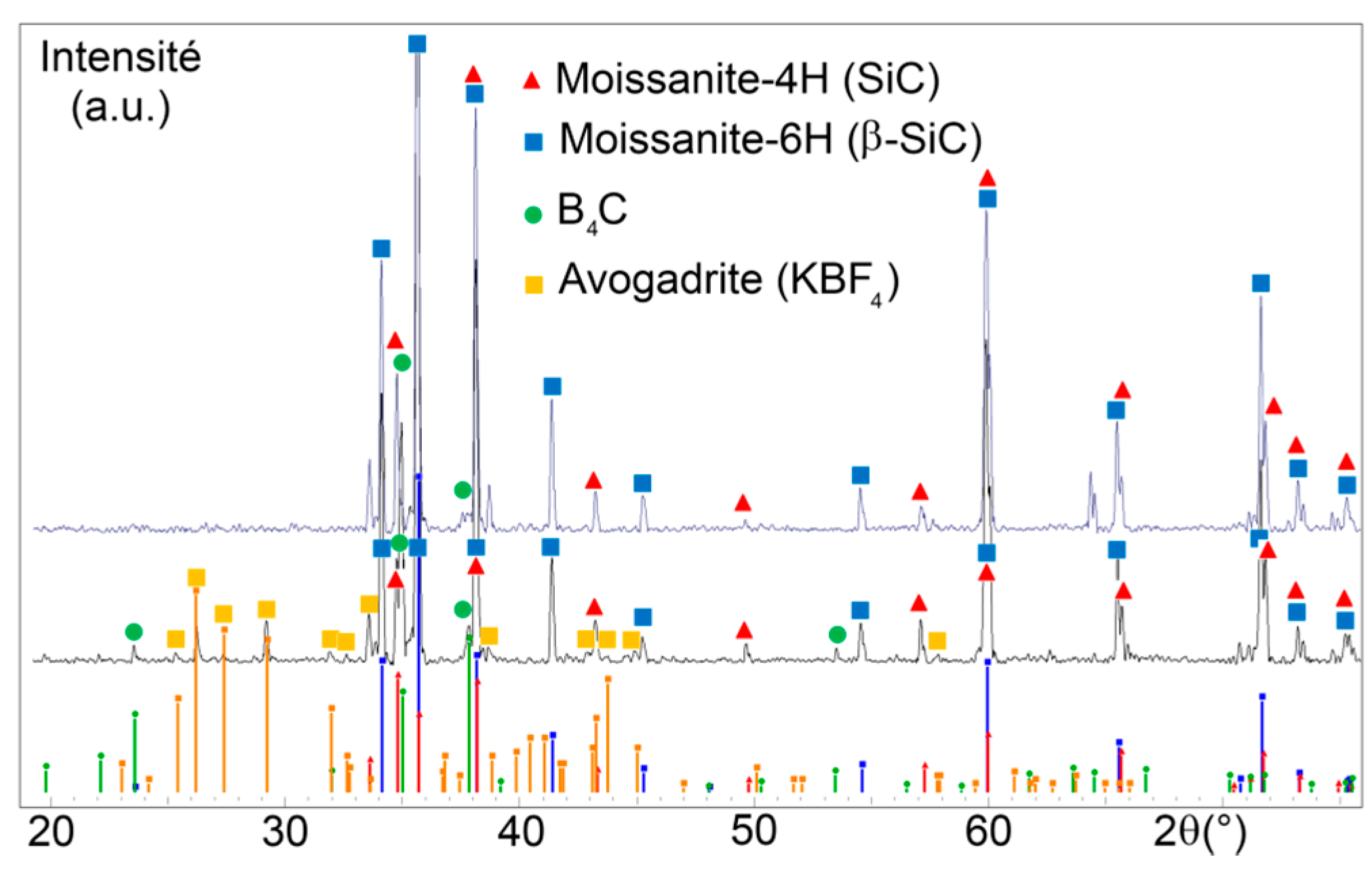
X-ray diffractogrammes of the pack powder before and after boriding are given in Figure 1. After treatment, the majority of B4C and KBF4 has disappeared, due to the diffusion of boron into the substrate, while silicon carbide and boron carbide are mostly spectators.
3.2. Characterisation of Borided H13 Steel
Plain substrates consist of a solid solution of chromium in substitution in ferrite. In the case of H13 tool steel, iron carbides are also present, most probably Fe7C3.
Figure 2a gives a cross-section of the surface, from the substrate (nr 1 on the figure) to the resin used to imprison the sample (nr 5). Small carbides can still be found in-depth (i.e., in region nr 1), which means that the heat treatment did not affect the steel microstructure in depth. The Fe2B boriding layer has quite pronounced “teeth” (nr 4 in Figure 2a). Its average thickness is 25 µm, in agreement with results from [9] in similar conditions.
In the substrate, but ~15 µm under the boriding layer, a region of dense and coarse carbides is observed (nr 2). This can be attributed to the fact that carbon has poor affinity for boron. Boron pushed carbon towards the substrate, leading to coarser carbides. Accordingly, just under the boriding layer (nr 3), these carbides are totally absent due to the presence of some boron.
Right under the layer, carbides are nearly absent on 10–20 µm thickness (nr 3), maybe due to the presence of molybdenum in H13 steel, that has an extremely limited affinity for boron. Then, a region of dense and coarse carbides is observed (nr 2), probably due to the diffusion of carbon, pushed away by boron from interstitial sites.
X-ray diffractogrammes shown in Figure 3 shows that the boriding layer obtained onto H13 tool steel consists of Fe2B and does not contain FeB. The ferritic substrate also appears. The list of all the obtained specimens is given in Table 1. The surface under study in the wear tests is also mentioned for each of them. The microhardnesses of the boride layer and of the subsequent coatings are given in Table 2. The relatively low value obtained for borided H13 steel is consistent with the absence of FeB. The detailed characterization of NiCrAlY and YSZ is already published in [52] and is therefore not given here. In Figure 2c, a cross section of YSZ porosity is shown for informative purpose.
3.3. Characterisation of Borided AISI 420 Steel
Figure 2b shows that precipitates similar to H13 appear after boriding AISI 420 steel (nr 1). They correspond to chromium carbides, precipitated during heat treatment. They are surrounded by ferrite with chromium as a substitution element.
The difference with H13 is that the layer just under iron borides is rich in chromium carbides (nr 2), which is further suggested by EDX analyses. This rejection of carbon from the layer to the substrate is again a consequence of the low affinity between carbon and boron. This presence of carbides inhibits the growth of long boride teeth in steel and reduces the influence of its anisotropy: the interface borides/substrate is more flat for borided AISI 420 than for borided H13 (i.e., the Fe2B “teeth” are deeper in the case of H13).
In the case of AISI 420 steel, the boriding layer has two phases, Fe2B (nr 3) and FeB that appears darker (nr 4) in Figure 2b. The thickness of the layer is ~45 µm, after correction accounting for the fact that the cross-section was not made exactly normal to the surface. Both Mo and Cr inhibit the FeB layer formation. However, the influence is much stronger in the case of Mo ([2], p. 32). This explains why the thickness is not significantly different on H13 (5.2% Cr; 1.4% Mo) and on AISI420 (12% Cr). The hardness of the outer boride layer is significantly higher than for borided H13, due to the presence of FeB (Table 2).
3.4. Pin-on-Disk Testing
Friction coefficients of the studied friction couples are given in Figure 4, as well as post-mortem front views of the corresponding balls (a–f). Figure 5 summarizes the obtained wear rates and friction coefficients.
Friction coefficient is significantly higher for the couple composed of untreated steels than for the other couples, in agreement with the previously cited literature. The other couples have quite similar friction coefficients with each other, but they differ in terms of dispersion: the couple FeB/Fe2B has a quite stable friction force; Dispersion due to the vibrations is somewhat higher for the other couples. The couple FeB/steel disk starts with a somewhat lower friction coefficient (~0.4), then increases to a value of ~0.8, which is probably not yet a steady state value.
Lines along the direction of relative motion are visible in Figure 4, for all the balls. Such lines are also found on the counter-body (Figure 6). A black solid could be recovered after most tests. These elements, in addition to the intense vibrations occurring during the tests, indicate a three-body abrasion. On AISI420 balls (Figure 4a,b), spots of stuck oxides are visible, further supporting this assumption. Figure 6a shows a front view of the wear track of an untreated disk. The dark spots, in backscattered electron mode, indicate similarly the formation of oxides.
Figure 6b,c indicated traces of fracture on the borided steel disks, as a consequence of the brittleness of the material. In the case of the disk coated with YSZ, the wear track is more difficult to image, however, it can be recognized as discontinuous flat zones in Figure 6d (where a discontinuous line shows the corresponding area). According to Figure 6e, these flat zones correspond to iron transferred from the ball to the zirconia rough coating. Similar pictures were obtained with a non borided ball, indicating a similar iron transfer onto YSZ whether the counter-body is borided or not (Figure 6f). This influence of roughness on the wear mechanism is confirmed by the measurements. Ra (arithmetic) and Rz (peak-to-valley, maximum) roughness were recorded for the three types of disks. For the H13 disk, Ra = 0.02 µm and Rz = 0.6 µm. For the borided disk, Ra = 0.75 µm and Rz = 5.6 µm. For the YSZ surface, Ra = 1.5 µm and Rz = 12.5 µm.
4. Discussion
All friction coefficient plots are directly exploitable, except in the case of borided AISI 420 steel against untreated H13. This increase of the friction coefficient with time may be due to the depth of the wear track on the ball. In the beginning of the test, the contact is mainly between FeB and the ferrite from the disk. Later on, since FeB layer is rather thin compared to the final wear track depth, contact also occurs progressively with Fe2B then ferrite from the ball. Measured friction coefficient is therefore a composite value accounting for these various phases, converging to ~1. Consequently, based on the left part of Figure 4c, the true friction coefficient of the FeB/H13 couple is likely to be ~0.4. The center of the micrograph showing the worn ball is not anymore iron boride, but the steel substrate.
No such trend is observed for the couple FeB/Fe2B, since the couple obtained after etching the boriding layers from the ball is AISI 420/Fe2B that has a comparable friction coefficient (~0.6 in both cases). It is worth noting that YSZ does not reduce the friction coefficient against FeB nor AISI 420 steel. It cannot therefore be specifically recommended to reduce the friction forces in present problem.
Unexpected trends are observed for the wear rates. Let us first exclude the steel/steel couple: it will be discussed later. It only plays the role of blank and is not exploitable if any exposure to aluminum is expected. The first paradox can be seen by comparing the wear rates inside each pairing. In two-body abrasion, it is generally accepted that the less hard surface is worn by the hardest surface and suffers from the highest mass loss. In Figure 5, this behavior is observed for the FeB/YSZ couple, where hard FeB is less worn than softer YSZ. For the other couples, the opposite is observed, suggesting a more complex behavior.
Boriding with Fe2B layer suffers from a high wear rate against AISI 420 steel ball (~0.002 mm³·(N·m)−1), much higher than reported steel by Soydan et al. for boriding on less alloyed steels [20]. A high wear rate (~0.001 mm³·(N·m)− 1) is also observed in the FeB/Fe2B couple, even though these materials are intrinsically known to be both wear resistant, and despite the quite low and more stable friction coefficient. The contact between these two different borides is not adequate, since the wear rates reported by Habig are much lower [33]. The high hardness of FeB is not sufficient to protect it from wear, due to the high tensile stress occurring in the layer (the expansion coefficient of FeB is much higher than steel). The detrimental behavior of Fe2B on H13 steel may be interpreted in the light of the structure of the layer on this substrate. Due to a stronger teeth-shape than on AISI 420 steel, the H13/Fe2B interface is more prone to initiate crack propagation. This explanation is further supported by the cracks observed in Figure 6b,c.
In contrast, the couple FeB/YSZ gives a more satisfactory result, with a wear rate divided by more than 10 for the ball. The boriding layers are here less worn than in the tests reported by Tabur et al. against alumina, at least 0.01 mm³·(N·m)−1 [15]. The relatively low hardness of zirconia compared to FeB is detrimental to the wear rate of zirconia that acts like an abradable material.
The second paradox is that the untreated couple benefits from the lowest wear rate. Such a metal/metal contact is normally supposed to generate adhesive wear. The relatively high friction coefficient suggests some adhesive wear, but oxides are also visible; Part of them remain stuck on the surfaces, as it can be seen in Figure 4a and Figure 6a. Oxides stuck on the disk may partly explain the absence of mass loss.
In terms of wear mechanism, and in the case of the AISI 420/H13 sliding couple, oxides are formed due to the local heating and are detached from time to time to become abrasive “third bodies”.
Three-body abrasion is also invoked for the couples involving borided H13 disks: black wear debris are observed and Figure 6b–c, again, suggests some loss of material from Fe2B.
For the couples involving YSZ, the porosity of the thermally sprayed coating probably plays a detrimental role in its wear resistance, leading to detachments of particles too, even in contact with a softer steel ball. This mechanism seems to be in competition with the transfer of iron to YSZ with, again, the possible formation of iron oxides, playing the role of a third body.
It is worth noting that the NiCrAlY bond located between YSZ and Fe2B proved efficient in avoiding YSZ spalling, since YSZ appears worn, but not detached, in present experiments.
In practice, two couples are supposed to be corrosion resistant in the presence of molten metal. From the wear point of view, FeB/Fe2B should be excluded, since it leads to the severe wear of both surfaces. The FeB/YSZ couple performs slightly better, since one of the surfaces, the relatively thin FeB layer, benefits from a more limited wear rate, while the other surface may be used as an abradable. The present short-term test provides useful indications to select the appropriate treatments for the final application, but do not replace field tests due to the testing load and time. In addition, the test is more demanding for the ball than for the disk. The ball boriding layer is completely or mostly worn and the tests cannot be made longer without changing the testing configuration.
5. Conclusions
Pack boriding was applied on two substrates, AISI 420 and H13 steels. Some samples were also plasma sprayed with zirconia. Friction tests were performed on six sliding couples, ranging from steel/steel to FeB/zirconia. The main results are the following:
- The boriding layer consists of solely irregular Fe2B on H13 tool steel and consists of both FeB and Fe2B on AISI 420 steel.
- The friction coefficients of FeB/Fe2B and FeB/YSZ couples are significantly lower than the steel/steel couple. In the first case, wear rates are ~10−3 mm³·(N·m)−1. In all the studied couples, dynamic friction coefficient is not inferior to 0.5, except possibly for the FeB/H13 couple when FeB remains nearly intact.
- Strong vibrations occur, due to three-body abrasion. The third bodies may be oxides due to the local heating of the steel, as well as Fe2B from treated H13 steel or porous YSZ from plasma sprayed disks.
- Even if both surfaces may be sufficiently corrosion resistant for foundry applications, the measured friction forces still suggest detrimental affinity between YSZ and iron borides. This couple may be recommended if the YSZ is the replaceable counter part of the slide. This conclusion is valid only in the case of a punctual exposure to molten metal. Since the corrosion by molten metal is only a selection criterion in the test, and not part of it, present work does not replace field tests. The tribological resistance studied here is a necessary condition to the resistance in real conditions, not a sufficient condition.
Author Contributions
Design of multilayer materials: P.D.A. and M.D.; Characterization and wear tests: P.D.A.; Project administration: P.D.A. and M.D.; Supervision and funding acquisition: M.D.
Funding
This research was funded by the Walloon Region of Belgium and the European Social Funding, grant number 415719.
Conflicts of Interest
The authors declare no conflict of interest. The funders had no role in the design of the study; in the collection, analyses, or interpretation of data; in the writing of the manuscript, or in the decision to publish the results.
References
- D’Ans, P.; Degrez, M. A strategy for the selection of multiple materials and processes fulfilling inherently incompatible functions: The case of successive surface treatments. Surf. Coat. Technol. 2015, 276, 349–359. [Google Scholar] [CrossRef]
- Von Matushka, A.G. Boronizing; Carl Hansen Verlag, Heyden & Son: München, Germany; Wien, Austria; Philadelphia, PA, USA, 1980. [Google Scholar]
- Audisio, S.; Caillet, M.; Galerie, A.; Mazille, H. Revêtements et Traitements de Surface—Fonctionnalités, Durabilité, Procédés; Presses Polytechniques et Universitaires Romandes: Lausanne, Switzerland, 1999. [Google Scholar]
- Spence, T.W.; Makhlouf, M.M. Characterization of the operative mechanism in potassium fluoborate activated pack boriding of steels. J. Mater. Process. Technol. 2005, 168, 127–136. [Google Scholar] [CrossRef]
- Keddam, M.; Kulka, M.; Makuch, N.; Pertek, A.; Małdzinski, L. A kinetic model for estimating the boron activation energies in the FeB and Fe2B layers during the gas-boriding of Armco iron: Effect of boride incubation times. Appl. Surf. Sci. 2014, 298, 155–163. [Google Scholar] [CrossRef]
- Kulka, M.; Makuch, N.; Pertek, A.; Maldzinski, L. Simulation of the growth kinetics of boride layers formed on Fe during gas boriding in H2-BCl3 atmosphere. J. Solid State Chem. 2013, 199, 196–203. [Google Scholar] [CrossRef]
- Flores-Rentería, M.A.; Ortiz-Domínguez, M.; Keddam, M.; Damián-Mejía, O.; Elias-Espinosa, M.; Flores-González, M.A.; Medina-Moreno, S.A.; Cruz-Avilés, A.; Villanueva-Ibañez, M. A Simple Kinetic Model for the Growth of Fe2B Layers on AISI 1026 Steel During the Powder-pack Boriding. High Temp. Mater. Proc. 2015, 34, 1–11. [Google Scholar] [CrossRef]
- Ortiz-Domínguez, M.; Keddam, M.; Elias-Espinosa, M.; Damián-Mejía, O.; Flores-Rentería, M.A.; Arenas-Flores, A.; Hernández-Ávila, J. Investigation of boriding kinetics of AISI D2 steel. Surf. Eng. 2014, 30, 490–497. [Google Scholar] [CrossRef]
- Genel, K. Boriding kinetics of H13 steel. Vacuum 2006, 80, 451–457. [Google Scholar] [CrossRef]
- Keddam, M.; Ortiz-Domínguez, M.; Elias-Espinosa, M.; Damián-Mejía, O.; Arenas-Flores, A.; Gómez-Vargas, O.A.; Abreu-Quijano, M.; Aldana-González, J.I.; Zuno-Silva, J. Growth Kinetics of the Fe2B Coating on AISI H13 Steel. Trans. Indian Inst. Met. 2015, 68, 433–442. [Google Scholar] [CrossRef]
- Dybkov, V.I. Growth of boride layers on the 13% Cr steel surface in a mixture of amorphous boron and KBF4. J. Mater. Sci. 2007, 42, 6614–6627. [Google Scholar] [CrossRef]
- Xie, F.; Chen, J.; Wang, S. Effects and mechanisms of an alternating current field on pack boriding. Vacuum 2018, 148, 41–47. [Google Scholar] [CrossRef]
- Türkmen, I.; Yalamaç, E. Growth of the Fe2B layer on SAE 1020 steel employed a boron source of H3BO3 during the powder-pack boriding method. J. Alloys Compd. 2018, 744, 658–666. [Google Scholar] [CrossRef]
- Kulka, M.; Makuch, N.; Piasecki, A. Nanomechanical characterization and fracture toughness of FeB and Fe2B iron borides produced by gas boriding of Armco iron. Surf. Coat. Technol. 2017, 325, 515–532. [Google Scholar] [CrossRef]
- Tabur, M.; Izciler, M.; Gul, F.; Karacan, I. Abrasive wear behavior of boronized AISI 8620 steel. Wear 2009, 266, 1106–1112. [Google Scholar] [CrossRef]
- Ulutan, M.; Celik, O.; Gasan, H.; Er, U. Effect of Different Surface Treatment Methods on the Friction and Wear Behavior of AISI 4140 Steel. J. Mater. Sci. Technol. 2010, 26, 251–257. [Google Scholar] [CrossRef]
- Gunes, I. Wear Behavior of Plasma Paste Boronized of AISI 8620 Steel with Borax and B2O3 Paste Mixtures. J. Mater. Sci. Technol. 2013, 29, 662–668. [Google Scholar] [CrossRef]
- Stewart, K. Boronizing protects metals against wear. Adv. Mater. Proc. 1997, 151, 23–25. [Google Scholar]
- Gök, M.; Küçük, Y.; Erdoğan, A.; Öge, M.; Kanca, E.; Günen, A. Dry sliding wear behavior of borided hot-work tool steel at elevated temperatures. Surf. Coat. Technol. 2017, 328, 54–62. [Google Scholar] [CrossRef]
- Soydan, Y.; Köksal, S.; Demirer, A.; Çelik, V. Sliding Friction and Wear Behavior of Pack-Boronized AISI 1050, 4140, and 8620 Steels. Tribol. Trans. 2008, 51, 74–81. [Google Scholar] [CrossRef]
- Düzcükoğlu, H.; Çalik, A.; İmrek, H.; Karakaş, M. Examination of Pitting and Wear in Borided, Carburized, and Borocarburized AISI 8620 Gears. Tribol. Trans. 2010, 53, 485–490. [Google Scholar] [CrossRef]
- Kayali, Y.; Anaturk, B. Investigation of electrochemical corrosion behavior in a 3.5 wt.% NaCl solution of boronized dual-phase steel. Mater. Des. 2013, 46, 776–783. [Google Scholar] [CrossRef]
- Cartier, M. Guide D’emploi des Traitements de Surfaces Appliqués aux Problèmes de Frottement; Tec&Doc: Paris, France, 2000. [Google Scholar]
- Ma, S.; Xing, J.; Fu, H.; He, Y.; Bai, Y.; Li, Y.; Bai, Y. Interface characteristics and corrosion behaviour of oriented bulk Fe2B alloy in liquid zinc. Corros. Sci. 2014, 78, 71–80. [Google Scholar] [CrossRef]
- Biddulph, R.H. Boronizing for erosion resistance. Thin Solid Films 1977, 45, 341–347. [Google Scholar] [CrossRef]
- Dybkov, V.I.; Goncharuk, L.V.; Khoruzha, V.G.; Samelyuk, A.V.; Sidorko, V.R. Growth kinetics and abrasive wear resistance of boride layers on Fe-15Cr alloy. Mater. Sci. Technol. 2011, 27, 1502–1512. [Google Scholar] [CrossRef]
- Dokumaci, E.; Özkan, I.; Önay, B. Effect of boronizing on the cyclic oxidation of stainless steel. Surf. Coat. Technol. 2013, 232, 22–25. [Google Scholar] [CrossRef]
- Tsipas, D.N.; Triantafyllidis, G.K.; Kipkemoi Kiplagat, J.; Psillaki, P. Degradation behaviour of boronized carbon and high alloy steels in molten aluminium and zinc. Mater. Lett. 1998, 37, 128–131. [Google Scholar] [CrossRef]
- Hairy, P.; Dussaussois, R. Performance comparison of twelve new anti-soldering surface treatments for high pressure die casting. Fonderie Fondeur d’Aujourd’hui 2003, 227, 30–41. [Google Scholar]
- Yang, H.P.; Wu, X.C.; Min, Y.A.; Wu, T.R.; Gui, J.Z. Plasma boriding of high strength alloy steel with nanostructured surface layer at low temperature assisted by air blast shot peening. Surf. Coat. Technol. 2013, 228, 229–233. [Google Scholar] [CrossRef]
- Lou, D.C.; Akselsen, O.M.; Onsøien, M.I.; Solberg, J.K.; Berget, J. Surface modification of steel and cast iron to improve corrosion resistance in molten aluminium. Surf. Coat. Technol. 2006, 200, 5282–5288. [Google Scholar] [CrossRef]
- D’Ans, P.; Bondoux, C.; Degrandcourt, C.; Bakrim, M.; Dille, J.; Segers, L.; Degrez, M. Thermal fatigue of anticorrosive coatings and multilayer coatings: A performance index approach. Mater. Sci. Forum 2008, 595–598, 941–950. [Google Scholar] [CrossRef]
- Habig, K.H. Wear protection of steels by boriding, vanadizing, nitriding and hardening. Mater. Eng. 1980, 2, 83–92. [Google Scholar] [CrossRef]
- Habig, K.H. Adhesive wear of boride and nitride layers on steel. Inst. Phys. Conf. Ser. 1986, 75, (Sci. Hard Mater.). 963–971. [Google Scholar]
- Garcia-Bustos, E.; Figueroa-Guadarrama, M.A.; Rodríguez-Castro, G.A.; Gómez-Vargas, O.A.; Gallardo-Hernandez, E.A.; Campos-Silva, I. The wear resistance of boride layers measured by the four-ball test. Surf. Coat. Technol. 2013, 215, 241–246. [Google Scholar] [CrossRef]
- Bourithis, L.; Papaefthymiou, S.; Papadimitriou, G.D. Plasma transferred arc boriding of a low carbon steel: Microstructure and wear properties. Appl. Surf. Sci. 2002, 200, 203–218. [Google Scholar] [CrossRef]
- Cimenoglu, H.; Atar, E.; Motallebzadeh, A. High temperature tribological behaviour of borided surfaces based on the phase structure of the boride layer. Wear 2014, 309, 152–158. [Google Scholar] [CrossRef]
- Taktak, S. Tribological behaviour of borided bearing steels at elevated temperatures. Surf. Coat. Technol. 2006, 201, 2230–2239. [Google Scholar] [CrossRef]
- Joshi, A.; Hosmani, S.; Dumbre, J. Tribological Performance of Boronized, Nitrided, and Normalized AISI 4140 Steel against Hydrogenated Diamond-Like Carbon-Coated AISI D2 Steel. Tribol. Trans. 2015, 58, 500–510. [Google Scholar] [CrossRef]
- Yasuda, T.; Banno, A.; Ito, T.; Kiyoshi, K.; Ishibayashi, K. Thermal Spraying Composite Material Containing Molybdenum Boride and a Coat Formed by Thermal Spraying. U.S. Patent US6238807, 29 May 2001. [Google Scholar]
- Mizuno, H.; Kitamura, J.; Osawa, S.; Itsukaichi, T. Development of durable spray coatings in molten aluminum alloy. In Proceedings of the ITSC 2005 Conference, Bâle, Switzerland, 2–4 May 2005; ASM Thermal Spray Society: Materials Park, OH, USA, 2005; pp. 80–85. [Google Scholar]
- Medvedovski, E. Wear-resistant engineering ceramics. Wear 2001, 249, 821–828. [Google Scholar] [CrossRef]
- Ramalingam, S.; Zheng, L. Film-substrate interface stresses and their role in the tribological performance. Tribol. Int. 1995, 28, 145–161. [Google Scholar] [CrossRef]
- Kameo, K.; Friedrich, K.; Bartolomé, J.F.; Díaz, M.; López-Esteban, S.; Moya, J.S. Sliding wear of ceramics and cermets against steel. J. Eur. Ceram. Soc. 2003, 23, 2867–2877. [Google Scholar] [CrossRef]
- Suh, M.-S.; Chae, Y.-H.; Kim, S.-S. Friction and wear behavior of structural ceramics sliding against zirconia. Wear 2008, 264, 800–806. [Google Scholar] [CrossRef]
- Banchet, V.; Fridrici, V.; Abry, J.C.; Kapsa, P. Wear and friction characterization of materials for hip prosthesis. Wear 2007, 263, 1066–1071. [Google Scholar] [CrossRef]
- Basu, B.; Vitchev, R.G.; Vleugels, J.; Celis, J.P.; Van der Biest, O. Influence of humidity on the fretting wear of self-mated tetragonal zirconia ceramics. Acta Mater. 2000, 48, 2461–2471. [Google Scholar] [CrossRef]
- dos Santos de Almeida, E.; Milan, J.; Costa, H.; Krelling, A.; da Costa, C. Sliding wear of borided sintered AISI M2 steel coated with AlTiN/CrN multilayer. Wear 2018, 410–411, 11–24. [Google Scholar] [CrossRef]
- Standard Test Method for Wear Testing with a Pin-on-Disk Apparatus; G99-05; ASTM International: West Conshohocken, PA, USA, 2010.
- Holmberg, K.; Matthews, A. Coatings Tribology; Elsevier: Amsterdam, The Netherlands, 1994. [Google Scholar]
- Zambelli, G.; Vincent, L. Matériaux et Contacts—Une Approche Tribologique; Presses Polytechniques et Universitaires Romandes: Lausanne, Switzerland, 1998. [Google Scholar]
- D’Ans, P.; Dille, J.; Degrez, M. Thermal fatigue resistance of plasma sprayed yttria-stabilised zirconia onto borided hot work tool steel, bonded with a NiCrAlY coating: Experiments and modelling. Surf. Coat. Technol. 2011, 205, 3378–3386. [Google Scholar] [CrossRef] [Green Version]
- Habraken, L.; de Brouwer, J.-L. De Ferri Metallographia; Presses Académiques Européennes: Bruxelles, Belgium, 1966. [Google Scholar]
Figure 1.
Phase identification in the fresh and used pack powder. Bottom: theoretical rays; Middle: fresh powder; Top: used powder.
Figure 1.
Phase identification in the fresh and used pack powder. Bottom: theoretical rays; Middle: fresh powder; Top: used powder.

Figure 2.
(a) Iron boride layer on H13, SEM, secondary electrons, cross section; (b) iron boride layers on AISI 420, SEM. Backscattered electrons mode is selected, in order to show the double boriding layer, cross section; (c) cross-section of YSZ showing the porosity.
Figure 2.
(a) Iron boride layer on H13, SEM, secondary electrons, cross section; (b) iron boride layers on AISI 420, SEM. Backscattered electrons mode is selected, in order to show the double boriding layer, cross section; (c) cross-section of YSZ showing the porosity.

Figure 3.
X-ray diffractogrammes of the layer obtained by boriding H13 steel, after cleaning. The positions denoted by (+) show what would be the FeB diffractogramme.
Figure 3.
X-ray diffractogrammes of the layer obtained by boriding H13 steel, after cleaning. The positions denoted by (+) show what would be the FeB diffractogramme.

Figure 4.
Friction coefficient as a function of time and post mortem ball (SEM, secondary electrons, front views): (a) Ball: AISI 420, disk: H13; (b) Ball: AISI 420, disk: Fe2B layer; (c) Ball: FeB layer, disk: H13; (d) Ball: FeB layer, disk: Fe2B layer; (e) Ball: AISI 420, disk: yttria-stabilized zirconia (YSZ) coating; (f) Ball: FeB layer, disk: YSZ coating. The scales on the right are adjusted to the average diameter of the tracks.

Figure 5.
Wear rates and friction coefficients for the studied friction couples. Bars indicate dispersion of friction coefficient during the test rather than confidence intervals. No wear rate could be calculated for H13 disks because the mass variation is very low. Arrows indicate to which scale the graph refers to.

Figure 6.
Wear tracks on disks (SEM, front view): (a) AISI 420 against H13, backscattered electrons; (b) Cracks on worn borided H13 (ball: untreated AISI 420), secondary electrons; (c) Same as (b), but with borided AISI 420 ball; (d) Borided AISI 420 against YSZ, backscattered electrons; (e) Same track as (d): mapping of iron Kα ray signal, (f) Similar track on YSZ worn by untreated AISI 420.


Table 1.
Summary of the studied samples.
| Shape | Layers (From Outside to the Substrate) | Studied Material in Wear Test |
|---|---|---|
| Disk | H13 | H13 |
| Disk | Fe2B; H13 | Fe2B |
| Disk | YSZ; NiCrAlY; Fe2B | YSZ |
| Ball | AISI 420 | AISI 420 |
| Ball | FeB; Fe2B; AISI 420 | FeB |
Table 2.
Microhardness measurements, measured on the cross-section of the samples. Uncertainty is comprised between ~5% for the lowest hardness and ~15% for the highest hardness. Measurements were made on the ball and the disk with the highest number of layers (3rd and 5th on Table 1).
Table 2.
Microhardness measurements, measured on the cross-section of the samples. Uncertainty is comprised between ~5% for the lowest hardness and ~15% for the highest hardness. Measurements were made on the ball and the disk with the highest number of layers (3rd and 5th on Table 1).
| Material | AISI 420 | Fe2B | FeB | H13 | Fe2B | NiCrAlY | YSZ |
|---|---|---|---|---|---|---|---|
| Object | Ball | Ball | Ball | Disk | Disk | Disk | Disk |
| HV | 220 | 1600 | 2000 | 220 | 1300 | 320 | 1000 |
| Load (N) | 1.962 | 1.962 | 1.962 | 1.962 | 0.981 | 0.981 | 1.962 |
© 2018 by the authors. Licensee MDPI, Basel, Switzerland. This article is an open access article distributed under the terms and conditions of the Creative Commons Attribution (CC BY) license (http://creativecommons.org/licenses/by/4.0/).
Share and Cite
MDPI and ACS Style
D’Ans, P.; Degrez, M. Sliding Wear Behavior of Friction Couples Primarily Selected for Corrosion Resistance: Iron Boride/Iron Boride and Iron Boride/Yttria-Stabilized Zirconia. Metals 2018, 8, 1071. https://doi.org/10.3390/met8121071
AMA Style
D’Ans P, Degrez M. Sliding Wear Behavior of Friction Couples Primarily Selected for Corrosion Resistance: Iron Boride/Iron Boride and Iron Boride/Yttria-Stabilized Zirconia. Metals. 2018; 8(12):1071. https://doi.org/10.3390/met8121071
Chicago/Turabian StyleD’Ans, Pierre, and Marc Degrez. 2018. "Sliding Wear Behavior of Friction Couples Primarily Selected for Corrosion Resistance: Iron Boride/Iron Boride and Iron Boride/Yttria-Stabilized Zirconia" Metals 8, no. 12: 1071. https://doi.org/10.3390/met8121071
Note that from the first issue of 2016, this journal uses article numbers instead of page numbers. See further details here.