Diffusion Bonding of Ti2AlNb Alloy and High-Nb-Containing TiAl Alloy: Interfacial Microstructure and Mechanical Properties
by
 and
and
Hong Bian
1,2, 
Yuzhen Lei
1,2,*,
Wei Fu
1,2,
Shengpeng Hu
1,2,
Xiaoguo Song
1,2,* and
Jicai Feng
1,2 1
State Key Laboratory of Advanced Welding and Joining, Harbin Institute of Technology, Harbin 150001, China
2
Shandong Provincial Key Lab of Special Welding Technology, Harbin Institute of Technology at Weihai, Weihai 264209, China
*
Authors to whom correspondence should be addressed.
Metals 2018, 8(12), 1061; https://doi.org/10.3390/met8121061
Submission received: 22 November 2018
/
Revised: 11 December 2018
/
Accepted: 11 December 2018
/
Published: 14 December 2018
(This article belongs to the Special Issue Science, Characterization and Technology of Joining and Welding)
Abstract
:In this study, reliable Ti2AlNb/high-Nb-containing TiAl alloy (TAN) joints were achieved by diffusion bonding. The effects of bonding temperature and holding time on the interfacial microstructure and mechanical properties were fully investigated. The interfacial structure of joints bonded at various temperatures and holding times was characterized by scanning electron microscopy (SEM), energy dispersive spectrometer (EDS) and X-ray diffraction (XRD). The results show that the typical microstructure of the Ti2AlNb substrate/O phase/Al(Nb,Ti)2 + Ti3Al/Ti3Al/TAN substrate was obtained at 970 °C for 60 min under a pressure of 5 MPa. The formation of the O phase was earlier than the Al(Nb,Ti)2 phase when bonding temperature was relatively low. When bonding temperature was high enough, the Al(Nb,Ti)2 phase appeared earlier than the O phase. With the increase of bonding temperature and holding time, the Al(Nb,Ti)2 phase decomposed gradually. As the same time, continuous O phase layers became discontinuous and the Ti3Al phase coarsened. The maximum bonding strength of 66.1 MPa was achieved at 970 °C for 120 min.
1. Introduction
As new lightweight and high-temperature structure materials, Ti2AlNb alloy and high-Nb-containing TiAl alloys (abbreviated as TAN alloys) have received significant attention in the aerospace field [1,2,3]. The addition of the Nb element gives them excellent properties, such as low density, high specific strength, favorable oxidation, creep resistance [4], and especially high temperature properties. The serving temperatures of Ti2AlNb alloys and TAN alloys are 650–700 °C and up to 900 °C, respectively [5,6]. Based on the above advantages and their different serving temperatures, the two alloys have become the most promising candidates for hot-section components with temperature gradients in aero-engines [7,8,9]. However, it is difficult to make them into large-scale and complex components, due to their poor workability [10,11]. Therefore, it is significant and necessary to join them together, in order to make full use of their respective advantages and extend their applications.
Up to now, fusion welding, friction welding, and brazing have been employed for joining Ti3Al based alloys or TiAl based alloys. However, defects such as cracks and voids usually appear in the joints obtained by fusion or friction welding, which can lead to hidden dangers in practical applications [12,13,14]. In brazing, the addition of filler can easily introduce impurities [15,16]. Diffusion bonding, an advanced and efficient method, has been proven to overcome the problems encountered in the above-mentioned welding techniques [17,18,19]. Some studies on diffusion bonding TiAl based alloys using interlayers such as Ni and Ti/Al have been reported [20,21]. In addition, several researchers have attempted to join Ti2AlNb based alloys by direct diffusion bonding [22,23]. Sound joints were obtained, and the joint strength was almost equal to the substrate strength using this technique. However, these previous studies mainly focused on joining the same, rather than different kinds of, Ti-Al based alloys. To date, reports on joining different kinds of Ti-Al based alloys are rare. Zou et al. [24] joined Ti-22Al-23Nb-2Ta alloy and Ti-46.2Al-2Cr-2Nb-0.15B alloy by direct diffusion bonding. At low temperature, the Al(Nb,Ti)2 phase was formed in the interface region adjacent to the O phase. When bonding temperature was relatively high, the Al(Nb,Ti)2 phase did not form, but a B2-enriched zone formed instead after long bonding time.
In our work, direct diffusion bonding was applied to join a Ti2AlNb (Ti3Al-based) alloy and a TAN (TiAl-based) alloy. The interfacial microstructure of bonded joints was characterized, and its evolution with changing bonding temperature and holding time was investigated. The shear strength of joints was tested, and surface analyses of the fracture were conducted to understand the mechanism of the fracture.
2. Experimental Section
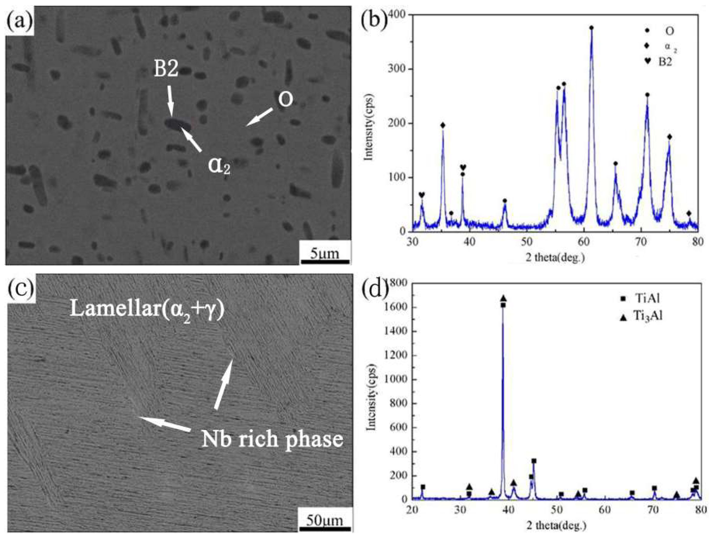
In this study, a Ti2AlNb alloy with a nominal composition of Ti-22Al-25Nb (atom %) was provided by BaoTai Group, Shanxi, China. TAN alloy (Ti-45Al-8.5Nb (W, B, Y) (atom %)) was provided by the State Key Laboratory for Advanced Metals and Materials, Beijing, China. Figure 1 shows backscattered electron (BSE) images and X-ray diffraction (XRD) patterns of the Ti2AlNb and TAN alloys. It reveals that the Ti2AlNb alloy was composed of black α2-Ti3Al phase, grey O-Ti2AlNb phase, and little white B2 phase around the α2-Ti3Al phase (Figure 1a), and the TAN alloy consisted of γ-TiAl phase, α2-Ti3Al phase (in lamellar colony structure [10]), and a little Nb-rich phase (Figure 1c).
Before the bonding experiment, both Ti2AlNb alloy and TAN alloy were cut into two kinds of rectangular specimens, with dimensions of 5 mm × 5 mm × 3 mm and 20 mm × 10 mm × 3 mm, by linear cutting. The joining surfaces of all specimens were ground by SiC grit papers down to 2000 grit, then cleared ultrasonically in acetone solution for ~20 min and dried by air blowing. Ti2AlNb alloy was well overlapped on TAN alloy under a pressure of 5 MPa; the schematic diagram of assembling parts is shown in Figure 2a. Bonding took place in a furnace under a vacuum of 1.3–2.0 × 10⁻³ Pa. First of all, the bonding specimens were heated to bonding temperature (930 °C–1010 °C) at a rate of 20 °C/min. Afterwards, they were held for a certain time (60 min to 150 min), and then cooled down to 600 °C at a rate of 10 °C/min. Eventually, the specimens were cooled down to room temperature spontaneously in the furnace.
After direct diffusion bonding, the cross-sections of the Ti2AlNb/TAN bonded joints were characterized by scanning electron microscopy (SEM, MERLIN Compact, Zeiss) (Stuttgart, Germany), and the composition of each phase in the joints was analyzed by energy dispersive spectrometer (EDS, OCTANE PLUS, EDAX) (Mahwah, NJ, USA). The shear tests were conducted at a constant speed of 0.5 mm/min by a universal testing machine (5967, Instron, Boston, MA, USA), and the schematic diagram of the shear test experiment is shown in Figure 2b. At least five samples obtained in same bonding condition were used to determine the average shear strength. SEM, EDS, and X-ray diffraction spectrometer equipped with Cu-Kα (XRD, DX-2700, Dandong Haoyuan Instrument Co., Ltd., Dandong, China) were applied to identify the fracture locations and phases on the fracture surface.
3. Results and Discussion
3.1. Typical Interfacial Microstructure of Ti2AlNb/TAN Bonded Joints
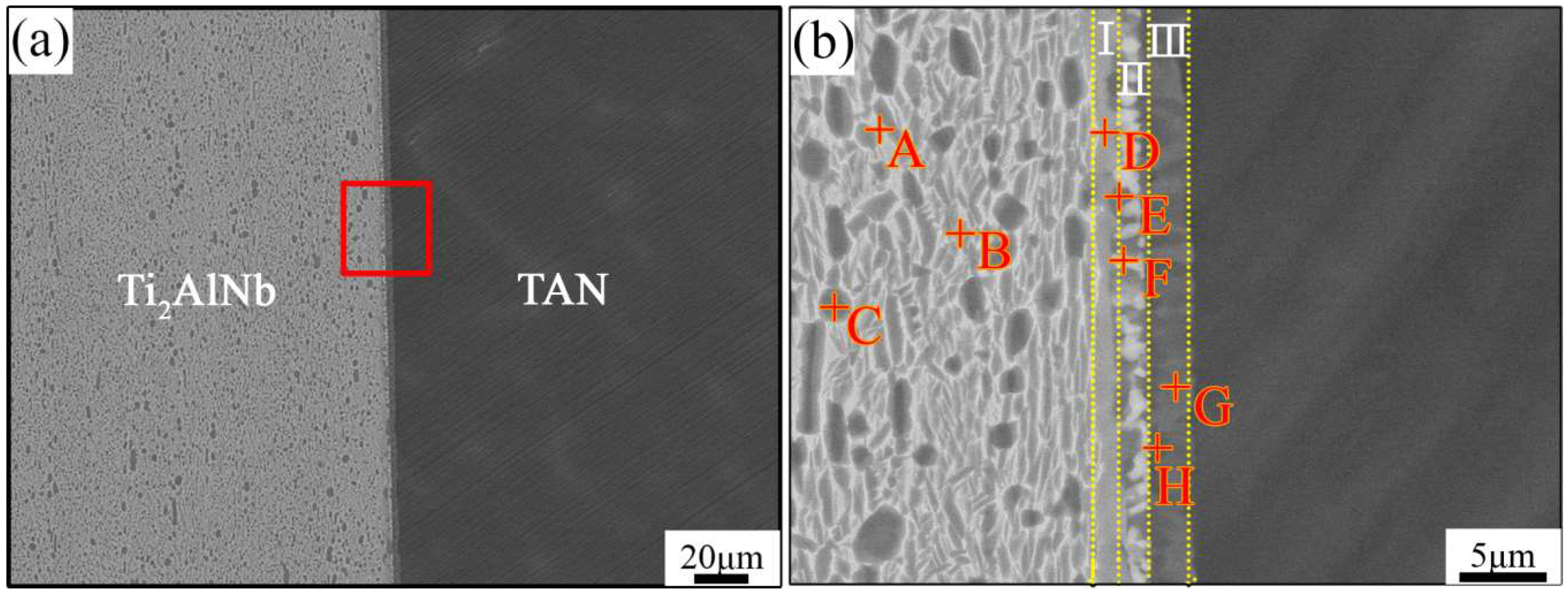
Figure 3a illustrates the typical interfacial microstructure of Ti2AlNb/TAN joints bonded at 970 °C for 60 min under a pressure of 5 MPa. It shows that reliable bonded joints without any pores or microcracks were achieved. In order to further investigate the interfacial microstructure of the Ti2AlNb/TAN bonded joints, a high-magnification image is given in Figure 3b. For a better description, the joint can be divided into three zones according to the different morphology. Zone I, adjacent to the Ti2AlNb substrate, was a continuous light gray layer (marked as D). Zone II mainly consisted of alternating black and white particles (marked as E and F, respectively). Zone III, adjacent to the TAN substrate, was alternating dark grey and black particles (marked as G and H, respectively). The corresponding EDS results of each phase in the joints are listed in Table 1. The EDS result of spot D in zone I suggests the presence of Ti, Al, and Nb in ratio of 2:1:1, which corresponds to O phase. Spots E in zone II, and G and H in zone III, mainly contained Ti and Al. The content of Ti was higher than that of Al. Combined with their morphology, similar to that of the α2-Ti3Al phase in the Ti2AlNb substrate, the phases could be regarded as α2-Ti3Al phases with different content of Nb. In addition, according to the experimental isotherm section of Ti-Al-Nb at 1000 °C [25] and in Reference [24], the white phase (marked as spot F) in zone II was an Al(Nb,Ti)2 phase. The components of the Ti2AlNb substrate adjacent to the joint are also given in Table 1. Obviously, the microstructure of theTi2AlNb substrate also consisted of grey O phase, black α2-Ti3Al phase, and white B2 phase, but it is worth mentioning that the quantity of B2 phase in the Ti2AlNb substrate adjacent to the joint was higher than in the area far from the joint. Therefore, the typical interfacial microstructure of Ti2AlNb/TAN joint bonded at 970 °C for 60 min was Ti2AlNb substrate/O phase/Al(Nb,Ti)2 + Ti3Al/Ti3Al/TAN substrate.
Based on the above analyses on the interfacial microstructure of the bonded Ti2AlNb/TAN joint and the microstructure of the Ti2AlNb substrate adjacent to the seam, the proposed evolution of the bonded joint is as follows. Due to the concentration gradients of Al and Nb atoms for the two substrates, in the bonding process, Al atoms diffused from the TAN substrate to the Ti2AlNb substrate, and Nb atoms diffused in the opposite direction. Moreover, the diffusion velocity of Al atoms was faster than that of Nb atoms, because the atomic mass of Al atoms is only a quarter of that of Nb atoms. For the Ti2AlNb substrate, a part of the O phase gradually transformed into B2 phase in the processes of heating and isothermal periods, according to the diagram of Ti3Al-Nb [26]. Therefore, when Al atoms diffused to the Ti2AlNb substrate, the B2 phase combined with Al atoms to generate Al(Nb,Ti)2 phase and Ti3Al phase by eutectoid reaction of Ti2AlNb(B2) + Al → Al(Nb,Ti)2 + Ti3Al. Hence, the (Al(Nb,Ti)2 + Ti3Al) mixed layer (zone II) was formed [27]. The Al(Nb,Ti)2 phase possessed the same structure as the AlNb2 phase, but was different from the common AlNb2 phase. The reason for formation of Al(Nb,Ti)2 phase was that Nb atoms in AlNb2 phase were partly replaced by Ti atoms with solid solution of Ti at high temperature [24]. Therefore, zone I could be regarded as a phase transformation zone. After the mixed zone II formed, excess Al atoms passed through the mixed layer into the Ti2AlNb substrate. As an Nb-rich and Al-depleted phase, B2 phase transformed into O phase when the concentration of Al exceeded its solubility in B2 phase. Afterwards, Nb atoms in B2 phase started to diffuse into other phases. Moreover, α2 phase was an Al-rich and Nb-depleted phase, so Nb atoms easily diffused into α2 phase and distorted its lattice, leading to the transformation of α2 phase into O phase. Eventually, a continuous O phase near the Ti2AlNb substrate in zone I was formed. In brief, the formation of zone I was mainly caused by the transformation of B2 phase and α2 phase. Zone III, containing Ti3Al phase, could also be regarded as a phase transformation zone. It was formed by the following two aspects: On one hand, a reaction of 3TiAl → Ti3Al + 2Al occurred, with the Al atoms decreasing. On the other hand, partial Ti atoms diffused to the TAN alloy and took part in the reaction of TiAl + 2Ti → Ti3Al [28].
3.2. Effect of Bonding Parameters on the Interfacial Microstructure of Ti2AlNb/TAN Joints
It is well known that bonding parameters play important roles in the interfacial microstructure of bonded joints. Therefore, the interfacial microstructures of joints bonded at various parameters were characterized, as shown in Figure 4 and Figure 5. The corresponding EDS results of the spots marked in Figure 5c are listed in Table 2.
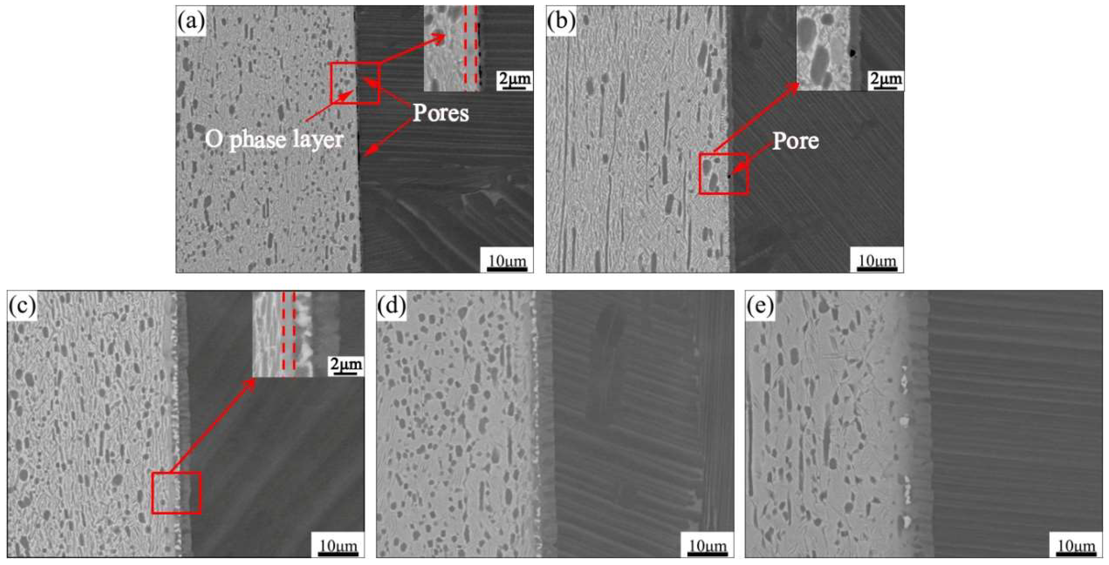
Figure 4a,b shows that some pores existed at the interface. This may have been because the bonding temperature was not high enough to cause considerable plastic deformation and/or enough atomic diffusion to guarantee complete contact. In addition, only O phase and Al(Nb,Ti)2 phase formed at the joints bonded at 930 °C and 950 °C, respectively, which is why the diffusion of Nb atoms was not sufficient to form Al(Nb,Ti)2 phase. On the other hand, Al atoms directly diffused into the Ti2AlNb substrate, causing the transformation of B2 phase and α2 phase into O phase (Figure 4a). When the temperature was high enough, as at 950 °C, the diffusion of Nb atoms was accelerated and the Nb atoms easily accumulated in the concentrations required to form the Al(Nb,Ti)2 phase [24]. In this case, Al atoms mainly participated in the formation of the Al(Nb,Ti)2 phase (Figure 4b). As temperature further increased to 970 °C, in addition to taking part in the formation of Al(Nb,Ti)2 phase, Al atoms also passed through the mixed layer to the Ti2AlNb substrate and formed the O phase, as shown in Figure 4c. Figure 4c–e shows that the Al(Nb,Ti)2 phase decreased gradually with increasing bonding temperature. High temperature enhanced the diffusion of Nb to the Ti2AlNb substrate, leaving insufficient Nb at the interface to form Al(Nb,Ti)2 phase [29]. As to the Ti3Al layer, its thickness obviously increased with the increase of the bonding temperature.
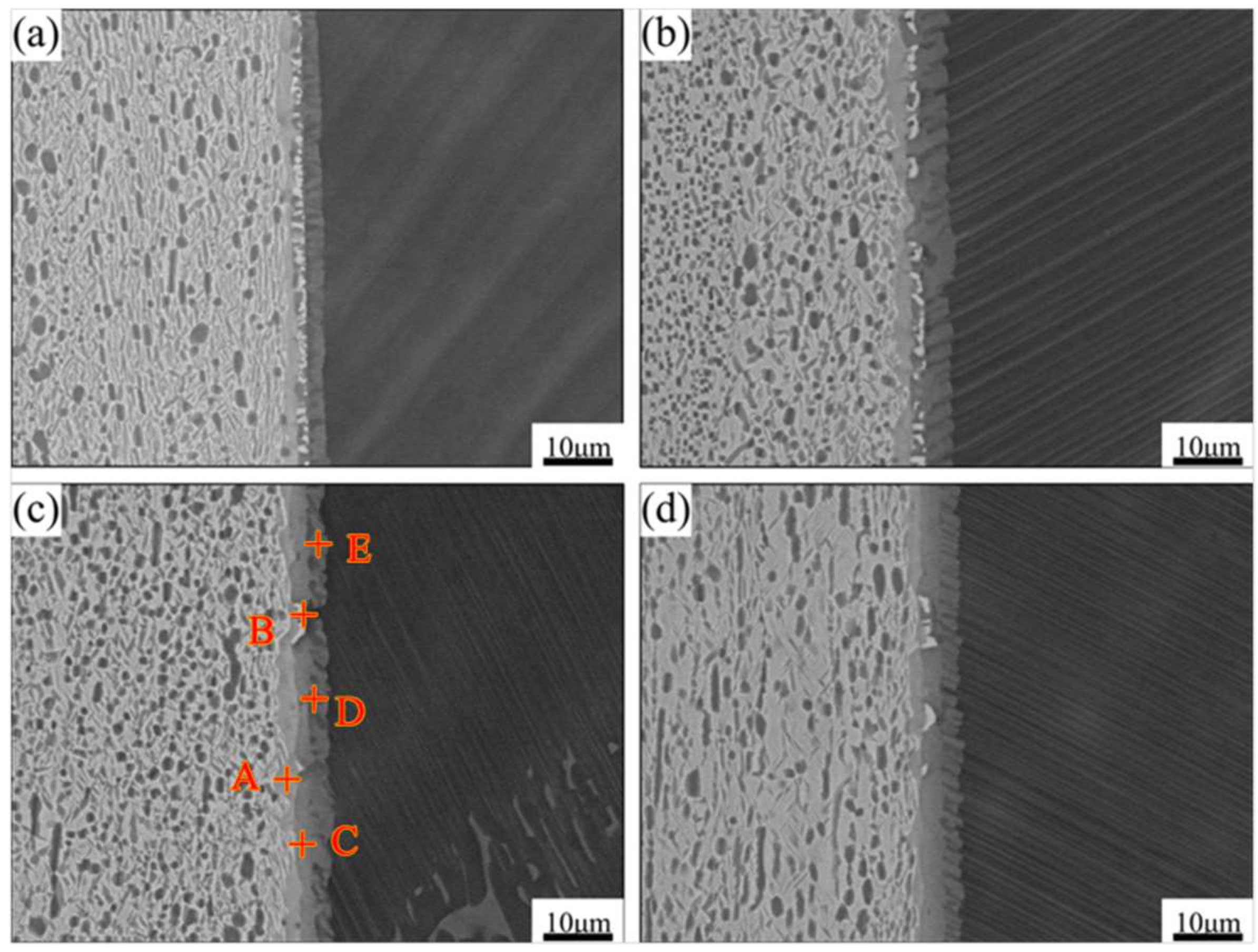
Figure 5 shows the evolution of the interfacial microstructure of Ti2AlNb/TAN joints bonded at 970 °C. Well-formed joints with no defects were obtained every time. With extended holding time, the amount of Al(Nb,Ti)2 phase reduced gradually, and eventually nearly disappeared when the holding time reached 120 and 150 min. In the isothermal period, along with the diffusion of Nb atoms, the concentration of Nb in the Al(Nb,Ti)2 phase decreased gradually, resulting in its decomposition. Along the TAN substrate, a Ti3Al transition layer consisting of two kinds of Ti3Al phases with different concentrations of Nb formed. The formation of one Ti3Al phase (marked as C) was due to the decomposition of Al(Nb,Ti)2 phase. The formation mechanism of the other one was the same as that of the Ti3Al phase marked as G in Figure 3b. The Ti3Al transition layer thickened and coarsened when holding time reached 150 min. On the other hand, the O phase layer became discontinuous, which resulted from the durative diffusion of Nb from Ti2AlNb to O phase inducing the transition of O phase to B2 phase.
3.3. Bonding Properties and Fracture Morphology of Bonded Ti2AlNb/TAN Joints
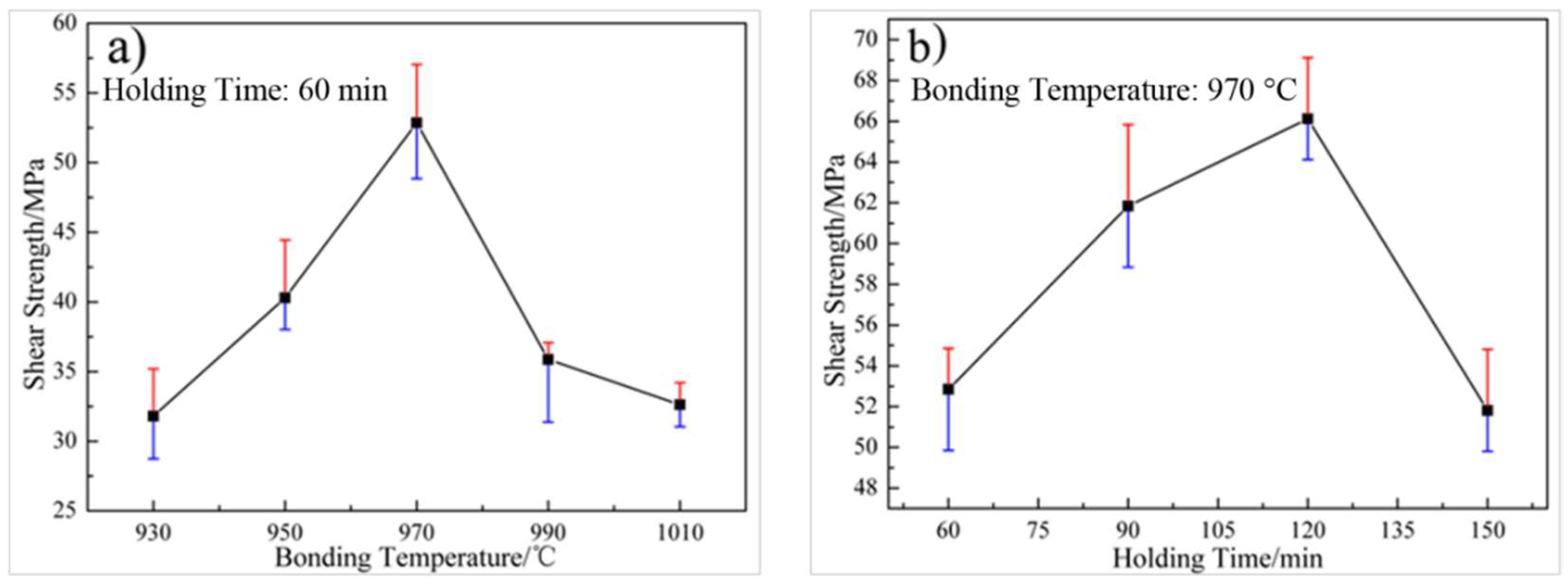
Figure 6 illustrates the effect of bonding temperature and holding time on the average shear strength of the bonded Ti2AlNb/TAN joints. It shows that the average shear strength exhibited the same tendency, first increasing and then decreasing, in both increasing temperature and time tests.
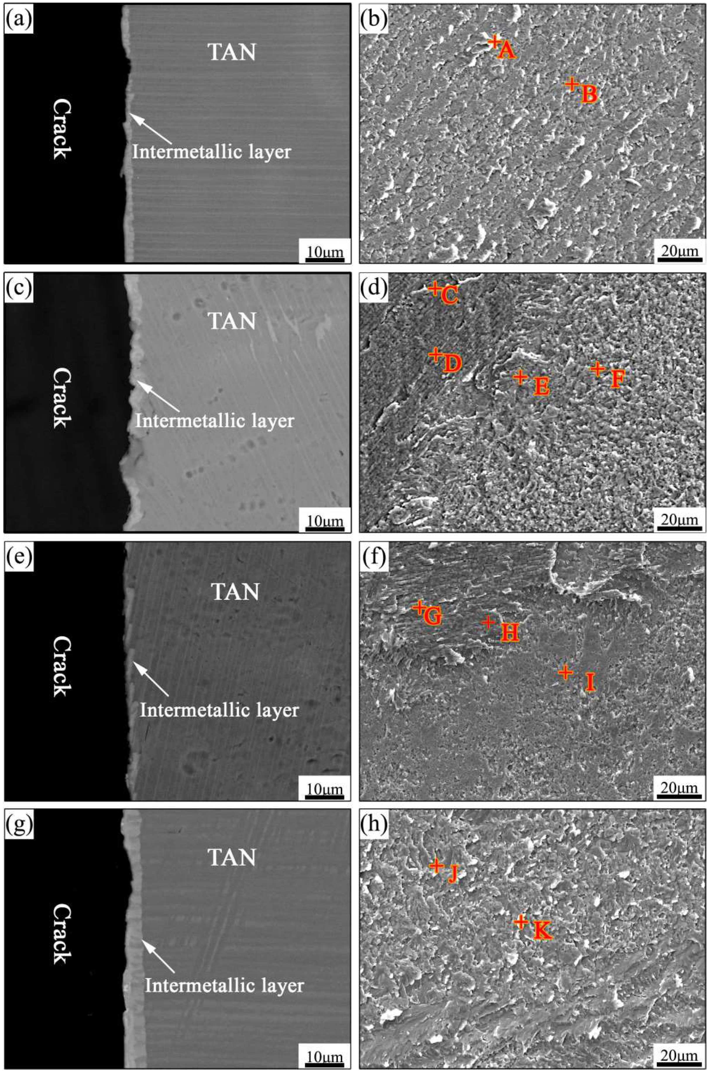
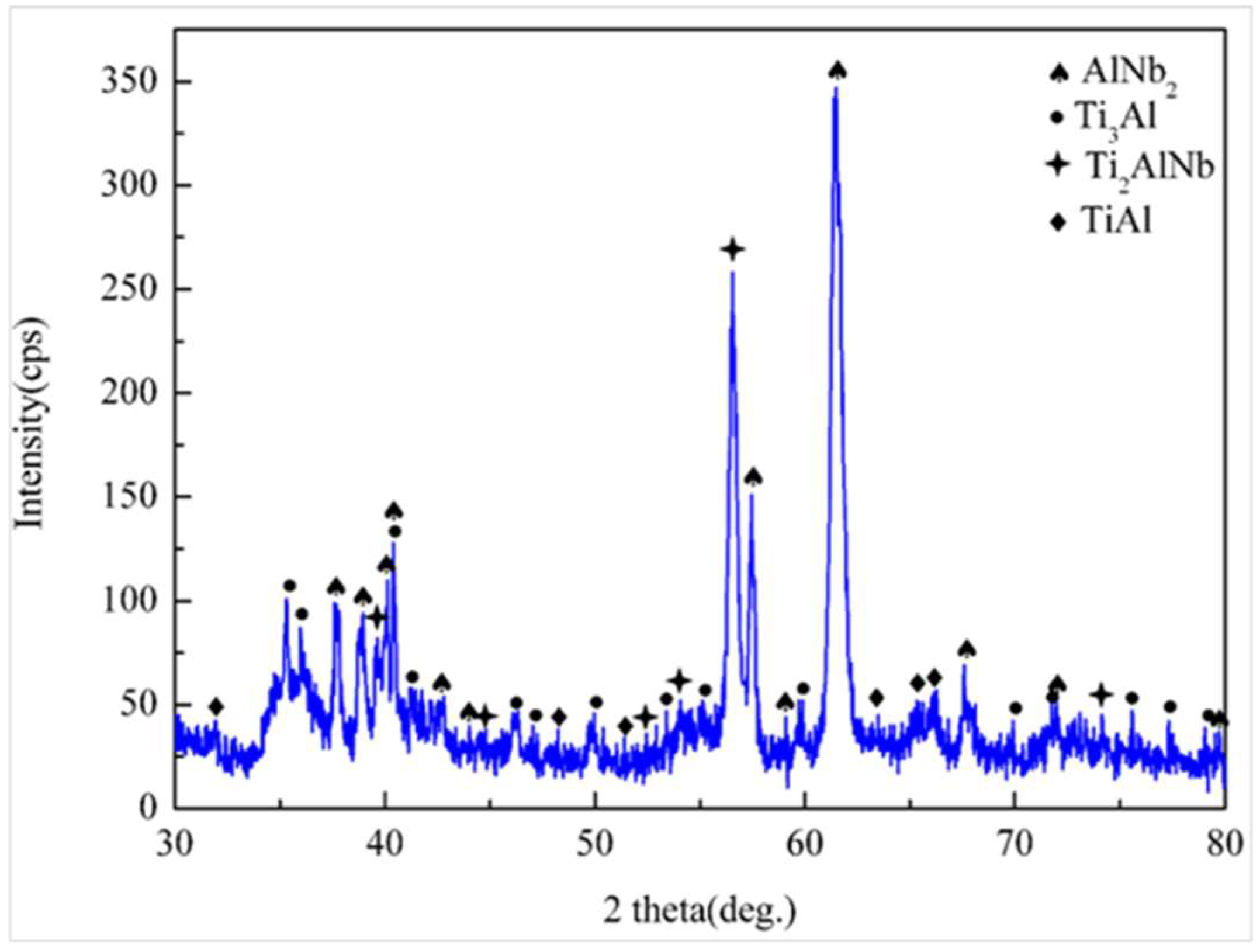
In order to further explore the fracture mechanism of the joints, fracture analyses were carried out. Furthermore, the relationship between interfacial microstructures and joining properties was established. Figure 7 shows the cross-section BSE images and fractography of joints made at different bonding temperatures and holding times, taken after shear test. The corresponding EDS results were listed in Table 3. All the fracture presented characteristic cleavage facets. As shown in Figure 7a–b, it was observed that the cracks mainly initiated in the mixed layer, which consisted of Al(Nb,Ti)2 (spot A) and Ti3Al phases (spot B). The fracture, which was obtained at 970 °C for 60 min (Figure 7c–d), also included Al(Nb,Ti)2 (spot C) and Ti3Al phases. However, it can be clearly seen that there were two types of Ti3Al phases with different contents of the Nb element. The Ti3Al phase with lower content of Nb (spot D) lay in the Ti3Al layer, and the one with the higher content of Nb (spot E or F) lay in the mixed layer. It can therefore be concluded that the cracks were mainly through the mixed layer and the Ti3Al layer. For further analyses, XRD analysis of the fracture surface on the TAN side after shear test of the joints at 970 °C/60 min/5 MPa was carried out, for which the XRD patterns are given in Figure 8. According to the results shown in Figure 8, Al(Nb,Ti)2 phase, which had the same structure as AlNb2 phase [24], and Ti3Al phase were detected from the fracture surfaces. The above results further confirmed the above analyses. When the holding time was extended to 120 min (Figure 7e–f), the fracture surface mainly consisted of TiAl phase (spot G) and two kinds of Ti3Al phase (spots H and I). It was concluded that there was little Al(Nb,Ti)2 phase either in the joints or in Ti3Al transition layer. The joints mainly fractured in the Ti3Al transition layer, and partly in the interface between the Ti3Al transition layer and the TAN substrate, which had the maximum shear strength. With holding time extended to 150 min (Figure 7g–h), the fracture only included two types of Ti3Al phase (spots J and K). Hence, the crack initiated and propagated in the transition layer.
For the joints created at 930 °C for 60 min, plenty of pores existed in the joints, decreasing the real bond area. Shear strength was therefore poor. As the bonding temperature increased, a compact contact was guaranteed and sufficient reactions occurred, following the interdiffusion of atoms. Continuous intermetallic compounds (IMCs) layers, including O phase layer, (Al(Nb,Ti)2 + Ti3Al) mixed phase layer, and Ti3Al phase layer (in Figure 4), formed at the interface. Therefore, an increasing shear strength was obtained, with the highest 52.9 MPa, achieved in joints made at 970 °C for 60 min. Whereas, with the further increase of bonding temperature, the Ti3Al layer thickened and Ti3Al grains coarsened, apparently decreasing the shear strength.
As the holding time increased, the Al(Nb,Ti)2 phase decomposed gradually and the Ti3Al transition layer formed (in Figure 5), which increased the shear strength of the joints [24]. The shear strength increased steadily and reached its highest value of 66.1 MPa at 970 °C for 120 min, as shown in Figure 6b. With the holding time further increased, despite the fact that the reduction of Al(Nb,Ti)2 phase was beneficial to performance of the joints, the mechanical properties of the joint still decreased by reason of thickening of the Ti3Al transition layer and coarsening of Ti3Al grains.
Based on the above analysis of interfacial microstructure and fracture results, it was concluded that the Al(Nb,Ti)2 phase was detrimental to the Ti2AlNb/TAN bonded joints, due to its hardness and brittleness. High bonding temperature or long holding time enhanced the diffusion of atoms, which caused the decrease of Al(Nb,Ti)2 phase and therefore better bonded joints. However, further increase of the bonding temperature or the holding time promoted the excessive growth of Ti3Al phase, which resulted in a decrease of the shear strength of Ti2AlNb/TAN bonded joints.
4. Conclusions
Bonding a Ti2AlNb alloy to a TAN alloy was achieved successfully by direct diffusion bonding. The effects of bonding temperature and holding time on the interfacial microstructure and mechanical properties of Ti2AlNb/TAN bonded joints were investigated in detail. Primary conclusions are summarized as follows.
- (1)
- The typical interfacial microstructure of the Ti2AlNb/TAN joints bonded at 970 °C for 15 min under a pressure of 5 MPa was Ti2AlNb substrate/O phase/Al(Nb,Ti)2 + Ti3Al/Ti3Al/TAN substrate.
- (2)
- Bonding temperature had a great influence on the priority of the formation of O phase and Al(Nb,Ti)2 phase. When bonding temperature was low, Al atoms diffused to the Ti2AlNb substrate directly, which caused the formation of O phase without Al(Nb,Ti)2 phase. When the bonding temperature was high enough, Nb atoms reached the desired concentration quickly. In this condition, Al atoms first reacted with B2 phase to generate Al(Nb,Ti)2 phase. Then, excess Al atoms passed though the mixed layer to the Ti2AlNb substrate and promoted the formation of O phase. As bonding temperature or holding time were further increased, Al(Nb,Ti)2 phase gradually decomposed into Ti3Al phase and a Ti3Al transition layer formed. Meanwhile, the O phase layer changed from a continuous state to a discontinuous one.
- (3)
- The Al(Nb,Ti)2 phase was hard and brittle, so the initial fracture location mainly occurred in the mixed layer. With the decomposition of Al(Nb,Ti)2 phase and the formation of transition layer, the shear strength was improved, and the average value reached 66.1 MPa when Ti2AlNb alloy and TAN alloy were bonded at 970 °C for 120 min. The fracture location mainly occurred in the Ti3Al transition layer and the fracture mode was brittle fracture.
Author Contributions
Conceptualization, H.B., Y.L. and X.S.; Methodology, X.S. and J.F.; Formal Analysis, Y.L. and S.H.; Data Curation, Y.L. and S.H.; Writing-Original Draft Preparation, H.B.; Writing-Review & Editing, W.F. and S.H.; Supervision, X.S. and J.F.; Funding Acquisition, X.S.
Funding
This project is supported by National Natural Science Foundation of China (Grant Nos. 51775138, U1537206 and U1737205) and the Key Research & Development program of Shandong Province (No. 2017GGX40103 and 2016GGA10085).
Conflicts of Interest
The authors declare no conflict of interest.
References
- Lu, Z.-G.; Wu, J.; Guo, R.-P.; Xu, L.; Yang, R. Hot deformation mechanism and ring rolling behavior of powder metallurgy Ti2AlNb intermetallics. Acta Metall. Sin. 2017, 30, 621–629. [Google Scholar] [CrossRef]
- Chu, Y.; Li, J.; Zhu, L.; Liu, Y.; Tang, B.; Kou, H. Microstructure evolution of a high Nb containing TiAl alloy with (α2 + γ) microstructure during elevated temperature deformation. Metals 2018, 8, 916. [Google Scholar] [CrossRef]
- Wang, S.; Xu, W.; Zong, Y.; Zhong, X.; Shan, D. Effect of initial microstructures on hot deformation behavior and workability of Ti2AlNb-based alloy. Metals 2018, 8, 382. [Google Scholar] [CrossRef]
- Li, T.-R.; Liu, G.-H.; Xu, M.; Fu, T.-L.; Tian, Y.; Misra, R.D.K.; Wang, Z.-D. Hot deformation behavior and microstructural characteristics of Ti–46Al–8Nb alloy. Acta Metall. Sin. 2018, 31, 933–944. [Google Scholar] [CrossRef]
- Yong, W.; Bin, L.; Rui, Y.; Xiaodong, H.; Ping, R. Local deformation and processing maps of Ti-24Al-17Nb-0.5 Mo alloy. Acta Metall. Sin. 2012, 25, 95–101. [Google Scholar]
- Liu, C.; Lu, X.; Yang, F.; Xu, W.; Wang, Z.; Qu, X. Metal Injection moulding of high Nb-containing TiAl alloy and its oxidation behaviour at 900 °C. Metals 2018, 8, 163. [Google Scholar] [CrossRef]
- Xiaoguo, S.; Jian, C.; Jiakun, L.; Liyan, Z.; Jicai, F. Reaction-diffusion bonding of high Nb containing TiAl alloy. Rare Metal Mat. Eng. 2014, 43, 28–31. [Google Scholar] [CrossRef]
- Feng, G.-J.; Li, Z.-R.; Liu, R.-H.; Feng, S.-C. Effects of joining conditions on microstructure and mechanical properties of Cf/Al composites and TiAl alloy combustion synthesis joints. Acta Metall. Sin. 2015, 28, 405–413. [Google Scholar] [CrossRef]
- Dong, D.; Zhu, D.; Wang, Y.; Wang, G.; Wu, P.; He, Q. Microstructure and shear strength of brazing TiAl/Si3N4 joints with Ag-Cu binary alloy as filler metal. Metals 2018, 8, 896. [Google Scholar] [CrossRef]
- Si, X.; Zhao, H.; Cao, J.; Song, X.; Tang, D.; Feng, J. Brazing high Nb containing TiAl alloy using Ti-28Ni eutectic brazing alloy: Interfacial microstructure and joining properties. Mater. Sci. Eng. A 2015, 636, 522–528. [Google Scholar] [CrossRef]
- Wu, Z.; Hu, R.; Zhang, T.; Zhou, H.; Kou, H.; Li, J. Microstructure determined fracture behavior of a high Nb containing TiAl alloy. Mater. Sci. Eng. A 2016, 666, 297–304. [Google Scholar] [CrossRef]
- Chen, G.; Zhang, B.; Liu, W.; Feng, J. Crack formation and control upon the electron beam welding of TiAl-based alloys. Intermetallics 2011, 19, 1857–1863. [Google Scholar]
- Zhang, K.; Liu, M.; Lei, Z.; Chen, Y. Microstructure evolution and tensile properties of laser-TIG hybrid welds of Ti2AlNb-based titanium aluminide. J. Mater. Eng. Perform. 2014, 23, 3778–3785. [Google Scholar] [CrossRef]
- Chen, X.; Xie, F.; Ma, T.; Li, W.; Wu, X. Microstructure evolution and mechanical properties of linear friction welded Ti2AlNb alloy. J. Alloys Compd. 2015, 646, 490–496. [Google Scholar] [CrossRef]
- Song, X.; Ben, B.; Hu, S.; Feng, J.; Tang, D. Vacuum brazing high Nb-containing TiAl alloy to Ti60 alloy using Ti-28Ni eutectic brazing alloy. J. Alloys Compd. 2017, 692, 485–491. [Google Scholar] [CrossRef]
- Cao, J.; Dai, X.; Liu, J.; Si, X.; Feng, J. Relationship between microstructure and mechanical properties of TiAl/Ti2AlNb joint brazed using Ti-27Co eutectic filler metal. Mater. Des. 2017, 121, 176–184. [Google Scholar] [CrossRef]
- Tang, B.; Qi, X.S.; Kou, H.C.; Li, J.S.; Milenkovic, S. Recrystallization behavior at diffusion bonding interface of high Nb containing TiAl Alloy. Adv. Eng. Mater. 2016, 18, 657–664. [Google Scholar] [CrossRef]
- Zou, G.-S.; Xie, E.-H.; Bai, H.-L.; Wu, A.-P.; Wang, Q.; Ren, J.-L. A study on transient liquid phase diffusion bonding of Ti-22Al-25Nb alloy. Mater. Sci. Eng. A 2009, 499, 101–105. [Google Scholar] [CrossRef]
- Cao, J.; Feng, J.C.; Li, Z.R. Microstructure and fracture properties of reaction-assisted diffusion bonding of TiAl intermetallic with Al/Ni multilayer foils. J. Alloys Compd. 2008, 466, 363–367. [Google Scholar] [CrossRef]
- He, P.; Zhang, J.; Zhou, R.; Li, X. Diffusion bonding technology of a titanium alloy to a stainless steel web with an Ni interlayer. Mater. Charact. 1999, 43, 287–292. [Google Scholar] [CrossRef]
- Duarte, L.I.; Ramos, A.S.; Vieira, M.F.; Viana, F.; Vieira, M.T.; Koçak, M. Solid-state diffusion bonding of gamma-TiAl alloys using Ti/Al thin films as interlayers. Intermetallics 2006, 14, 1151–1156. [Google Scholar] [CrossRef] [Green Version]
- Du, Z.; Jiang, S.; Zhang, K.; Lu, Z.; Li, B.; Zhang, D. The structural design and superplastic forming/diffusion bonding of Ti 2 AlNb based alloy for four-layer structure. Mater. Des. 2016, 104, 242–250. [Google Scholar] [CrossRef]
- Zou, G.S.; Bai, H.L.; Xie, E.H.; Wu, S.J.; Wu, A.P.; Wang, Q.; Ren, J.L. Solid diffusion bonding of Ti-22Al-25Nb O phase alloy. Chin. J. Nonferrous Met. 2008, 18, 577–582. [Google Scholar]
- Zou, J.; Cui, Y.; Yang, R. Diffusion bonding of dissimilar intermetallic alloys based on Ti2AlNb and TiAl. J. Mater. Sci. Technol. 2009, 25, 819–824. [Google Scholar]
- Hellwig, A.; Palm, M.; Inden, G. Phase equilibria in the Al-Nb-Ti system at high temperatures. Intermetallics 1998, 6, 79–94. [Google Scholar] [CrossRef]
- Muraleedharan, K.; Gogia, A.K.; Nandy, T.K.; Banerjee, D.; Lele, S. Transformations in a Ti-24AI-15Nb alloy: Part I. Phase equilibria and microstructure. Metall. Trans. A 1992, 23, 401–415. [Google Scholar] [CrossRef]
- Yang, S.J.; Nam, S.W.; Hagiwara, M. Phase identification and effect of W on the microstructure and micro-hardness of Ti2AlNb-based intermetallic alloys. J. Alloys Compd. 2003, 350, 280–287. [Google Scholar] [CrossRef]
- Cao, S.; Xiao, S.; Chen, Y.; Xu, L.; Wang, X.; Han, J.; Jia, Y. Phase transformations of the L12-Ti3Al phase in γ-TiAl alloy. Mater. Des. 2017, 121, 61–68. [Google Scholar] [CrossRef]
- Du, X.W.; Zhu, J.; Zhang, X.; Cheng, Z.Y.; Kim, Y.W. Composition change during creep in colonies oriented for easy-slip of Ti-46.5Al-2Cr-3Nb-0.2W. Mater. Sci. Eng. A 2000, 291, 131–135. [Google Scholar] [CrossRef]
Figure 1.
Microstructure and X-ray diffraction (XRD) patterns of substrates. (a,b) Ti2AlNb, (c,d) TAN.
Figure 1.
Microstructure and X-ray diffraction (XRD) patterns of substrates. (a,b) Ti2AlNb, (c,d) TAN.

Figure 2.
Schematic diagrams of (a) assembling diffusion bonding parts and (b) shear test experiment.
Figure 2.
Schematic diagrams of (a) assembling diffusion bonding parts and (b) shear test experiment.

Figure 3.
Typical interfacial microstructure of bonded joints at 970 °C/60 min/5 MPa. (a) Backscattered electron (BSE) image and (b) high-magnified image.
Figure 3.
Typical interfacial microstructure of bonded joints at 970 °C/60 min/5 MPa. (a) Backscattered electron (BSE) image and (b) high-magnified image.

Figure 4.
Interfacial microstructure of bonded joints for 60 min/5 MPa at different temperatures. (a) 930 °C, (b) 950 °C, (c) 970 °C, (d) 990 °C, and (e) 1010 °C.
Figure 4.
Interfacial microstructure of bonded joints for 60 min/5 MPa at different temperatures. (a) 930 °C, (b) 950 °C, (c) 970 °C, (d) 990 °C, and (e) 1010 °C.

Figure 5.
BSE images of interfacial microstructure of bonded joints at 970 °C/5 MPa for (a) 60 min, (b) 90 min, (c) 120 min, (d) 150 min.
Figure 5.
BSE images of interfacial microstructure of bonded joints at 970 °C/5 MPa for (a) 60 min, (b) 90 min, (c) 120 min, (d) 150 min.

Figure 6.
Effect of bonding parameters on the shear strength of joints. (a) Bonding temperature; (b) holding time.
Figure 6.
Effect of bonding parameters on the shear strength of joints. (a) Bonding temperature; (b) holding time.

Figure 7.
Fractured cross-section BSE images and fractography of the joints bonded at (a–b) 950 °C/60 min, (c–d) 970 °C/60 min, (e–f) 970 °C/120 min, and (g–h) 970 °C/150 min. (TAN side).
Figure 7.
Fractured cross-section BSE images and fractography of the joints bonded at (a–b) 950 °C/60 min, (c–d) 970 °C/60 min, (e–f) 970 °C/120 min, and (g–h) 970 °C/150 min. (TAN side).

Figure 8.
XRD patterns of the fracture surface after shear test of the joints bonded at 970 °C/60 min/5 MPa.
Figure 8.
XRD patterns of the fracture surface after shear test of the joints bonded at 970 °C/60 min/5 MPa.


Table 1.
Chemical compositions and possible phases of each spot marked in Figure 3b (atom %).
Table 1.
Chemical compositions and possible phases of each spot marked in Figure 3b (atom %).
| Spot | Ti | Al | Nb | Possible Phase |
|---|---|---|---|---|
| A | 54.84 | 21.78 | 23.37 | B2 |
| B | 55.24 | 24.09 | 20.67 | O |
| C | 59.85 | 24.91 | 15.24 | α2-Ti3Al |
| D | 52.25 | 27.83 | 19.93 | O |
| E | 56.28 | 26.87 | 16.85 | α2-Ti3Al |
| F | 42.55 | 36.69 | 20.75 | Al(Nb,Ti)2 |
| G | 54.53 | 35.25 | 10.22 | α2-Ti3Al |
| H | 55.81 | 27.84 | 16.35 | α2-Ti3Al |
Table 2.
Chemical compositions and possible phases of each spot marked in Figure 5c (atom %).
Table 2.
Chemical compositions and possible phases of each spot marked in Figure 5c (atom %).
| Spot | Ti | Al | Nb | Possible Phase |
|---|---|---|---|---|
| A | 52.34 | 27.50 | 20.07 | O |
| B | 43.91 | 34.80 | 21.29 | Al(Nb,Ti)2 |
| C | 51.33 | 33.45 | 15.23 | α2-Ti3Al |
| D | 56.78 | 33.78 | 9.43 | α2-Ti3Al |
| E | 53.22 | 35.89 | 10.89 | α2-Ti3Al |
Table 3.
Chemical compositions and possible phases of each spot marked in Figure 7 (atom %).
Table 3.
Chemical compositions and possible phases of each spot marked in Figure 7 (atom %).
| Spot | Ti | Al | Nb | Possible Phase | Corresponding IMC Layer |
|---|---|---|---|---|---|
| A | 49.77 | 38.29 | 11.44 | Al(Nb,Ti)2 | mixed layer |
| B | 51.91 | 31.88 | 16.22 | α2-Ti3Al | mixed layer |
| C | 44.82 | 38.31 | 16.87 | Al(Nb,Ti)2 | mixed layer |
| D | 52.78 | 33.74 | 13.48 | α2-Ti3Al | Ti3Al phase layer |
| E | 50.09 | 31.37 | 18.54 | α2-Ti3Al | mixed layer |
| F | 50.28 | 31.25 | 18.47 | α2-Ti3Al | mixed layer |
| G | 44.63 | 47.38 | 8.00 | TiAl | TAN substrate |
| H | 58.16 | 33.27 | 8.57 | α2-Ti3Al | transition layer |
| H | 53.09 | 31.47 | 15.44 | α2-Ti3Al | transition layer |
| J | 52.67 | 35.08 | 12.25 | α2-Ti3Al | transition layer |
| K | 51.82 | 30.72 | 17.46 | α2-Ti3Al | transition layer |
© 2018 by the authors. Licensee MDPI, Basel, Switzerland. This article is an open access article distributed under the terms and conditions of the Creative Commons Attribution (CC BY) license (http://creativecommons.org/licenses/by/4.0/).
Share and Cite
MDPI and ACS Style
Bian, H.; Lei, Y.; Fu, W.; Hu, S.; Song, X.; Feng, J. Diffusion Bonding of Ti2AlNb Alloy and High-Nb-Containing TiAl Alloy: Interfacial Microstructure and Mechanical Properties. Metals 2018, 8, 1061. https://doi.org/10.3390/met8121061
AMA Style
Bian H, Lei Y, Fu W, Hu S, Song X, Feng J. Diffusion Bonding of Ti2AlNb Alloy and High-Nb-Containing TiAl Alloy: Interfacial Microstructure and Mechanical Properties. Metals. 2018; 8(12):1061. https://doi.org/10.3390/met8121061
Chicago/Turabian StyleBian, Hong, Yuzhen Lei, Wei Fu, Shengpeng Hu, Xiaoguo Song, and Jicai Feng. 2018. "Diffusion Bonding of Ti2AlNb Alloy and High-Nb-Containing TiAl Alloy: Interfacial Microstructure and Mechanical Properties" Metals 8, no. 12: 1061. https://doi.org/10.3390/met8121061
Note that from the first issue of 2016, this journal uses article numbers instead of page numbers. See further details here.