Article

Experimental Characterization of the Primary Stability of Acetabular Press-Fit Cups with Open-Porous Load-Bearing Structures on the Surface Layer

1
Faculty of Engineering, University of Applied Science, Technology, Business and Design, Philipp-Müller-Str. 14, 23966 Wismar, Germany
2
Biomechanics and Implant Technology Research Laboratory, Department of Orthopedics, Rostock University Medicine, Doberaner Strasse 142, 18057 Rostock, Germany
3
Institute for Polymer Technologies e.V., Alter Holzhafen 19, 23966 Wismar, Germany
*
Author to whom correspondence should be addressed.
Metals 2018, 8(10), 839; https://doi.org/10.3390/met8100839
Submission received: 27 September 2018 / Revised: 16 October 2018 / Accepted: 16 October 2018 / Published: 17 October 2018
(This article belongs to the Special Issue Titanium Alloys for Biomedical Implants and Devices)

Abstract

:
Background: Nowadays, hip cups are being used in a wide range of design versions and in an increasing number of units. Their development is progressing steadily. In contrast to conventional methods of manufacturing acetabular cups, additive methods play an increasingly central role in the development progress. Method: A series of eight modified cups were developed on the basis of a standard press-fit cup with a pole flattening and in a reduced version. The surface structures consist of repetitive open-pore load-bearing textural elements aligned right-angled to the cup surface. We used three different types of unit cells (twisted, combined and combined open structures) for constructing of the surface structure. All cups were manufactured using selective laser melting (SLM) of titanium powder (Ti6Al4V). To evaluate the primary stability of the press fit cups in the artificial bone cavity, pull-out and lever-out tests were conducted. All tests were carried out under exact fit conditions. The closed-cell polyurethane (PU) foam, which was used as an artificial bone cavity, was characterized mechanically in order to preempt any potential impact on the test results. Results and conclusions: The pull-out forces as well as the lever moments of the examined cups differ significantly depending on the elementary cells used. The best results in pull-out forces and lever-out moments are shown by the press-fit cups with a combined structure. The results for the assessment of primary stability are related to the geometry used (unit cell), the dimensions of the unit cell, and the volume and porosity responsible for the press fit. Corresponding functional relationships could be identified. The findings show that the implementation of reduced cups in a press-fit design makes sense as part of the development work.

1. Introduction

Implants today are an important achievement of modern society and an indispensable part of daily life. To improve an implant design, it is important to build a knowledge base that allows insights gained to be integrated into new developments. Modern, generative manufacturing processes provide an excellent foundation for the support and acceleration of the knowledge required in the area of experimental development and for the transfer from result in application [1,2,3,4]. Developing implants beyond the current state of the art, for example in the field of orthopedics, is an interesting task for development engineers. Due to their outstanding mechanical and biocompatible properties, titanium and titanium alloys, in addition to other materials, are at the center of development work [5,6,7].
Of major interest is the implementation of open-porous structures in orthopedic implants. These structural elements provide excellent conditions to fulfil structural and functional requirements. Open-porous structures meet the mechanical requirements regarding surface quality as well as those regarding design conditions [8,9,10]. In addition, such structures offer a potential for solving the problems of different stiffnesses between human bone and full implants [11,12]. As a result of their geometry, open-pore structures offer the cells good conditions for nutrient supply, and consequently, the possibility to grow well into the pores. Characteristic features of open-pore structures like pore size and distribution as well as connectivity affect biological processes like cell migration and proliferation and as a result the regeneration process [3,13].
The applications of open-porous and load-bearing structures in orthopedic applications range from femoral stems, knee implants to artificial hip cups [3]. Harrison et al. developed a new surface architecture for orthopedic stem components to ensure a greater resistance against transverse motion. This allowed an enhanced primary fixation [14]. Jetté et al. designed a femoral stem with a diamond cubic lattice structure and assessed its potential as a biomimetic construct for load-bearing orthopedic implants [15]. Marin et al. evolved an acetabular cup with Trabecular TitaniumTM to increase osseointegration [16].
The design of the area between the implant and human bone or the transition boundary between the implant and human bone is crucial for the success of the substitution of bone with the implant. A large number of investigations are therefore concerned with the implementation of implant surfaces with biocompatible or bioactive properties [17,18,19,20]. The aim is to establish conditions that will optimally assist bone in growing in order to achieve maximum secondary stability [21,22,23,24,25].
Numerical simulations are also frequently used in the area of implant development as an indispensable link between constructive development ideas and experimental testing [26,27,28,29,30]. The success of an implantation is determined not only by secondary stiffness but also by primary anchoring strength [29,31,32]. Le Cann et al. investigated the influence of surface roughness on primary stability [33]. Goriainov et al. tested the interaction between the surface properties of the acetabular cup and its initial stability [34]. Gebert et al. studied the influence of press-fit parameters on the primary stability of uncemented femoral head resurfacing prostheses [35]. With this work, an influence of the surface roughness on the primary stability could be demonstrated. It is particularly remarkable that the primary stability can be improved up to a respective roughness value beyond which deterioration occurs is essentially influenced by the cup design. However, the influence of modifications to commercially available implants on primary stability must not be disregarded when considering the entire subject area [36,37]. Primary stability as a prerequisite for good osseointegration significantly influences the success of an implantation [29].
In the field of press-fit cups, experimental work evaluating the pull-out and lever-out behavior in preclinical as well as in post-clinical investigations is of particular interest for the assessment of anchoring strength [38,39,40,41,42,43]. Besides bones (cadavers) closed-cell foams are being used more and more often in their function as an artificial bone bed [37,44,45,46]. In addition to different PU (polyurethane) foams, EP-DUR polyurethane foams, polymethacrylamide (PMI) foams and a combination of a polyvinyl chloride (PVC) layer and a PMI foam have served as bone substitutes [47,48,49]. Although PU foam deviates from the properties of acetabular bone, it is well suited for experimental work due to its uniform cell structure and associated mechanical properties. This is mainly because of the reproducibility of the results, better availability and avoidance of ethical problems.
In the context of this work, standard acetabular cups in the press-fit version were constructively provided with a porous layer on the surface to experimentally determine the influence on primary stability. The porous structures were applied to a reduced-acetabular cup, the suitability of which for the characterization of primary stability has been evaluated in a previous study [50]. All acetabular cups were manufactured using additive manufacturing technology (Selective Laser Melting). The porous surface structures were varied constructively in order to generate different densities in the structural layer and to vary the structure-determining geometry. These constructively produced structures, though differing significantly, nevertheless aim to deliver bone-like properties as a load-bearing structural layer. Thus, forces occurring in the implant bed can be directly absorbed and transmitted by the implant. The porous structure, which has an osteoconductive effect and supports osteoinduction, can significantly improve primary stability [21,25].
The focus of the experimental work is the description of the impact of the applied structural geometry on the primary stability.

2. Materials and Methods

2.1. Cup Design

The modified cups (Figure 1) were designed on the basis of a conventional press-fit cup with a pole flattening. The suitability of a modified press-fit cup (reduced height) for the use in a development phase was verified in an earlier study [50]. All cups were designed in a reduced design with an equatorial cup diameter of 55.3 mm and a pole flattening of 1 mm. The height profiles of the cup were recorded (equatorial cup diameter 55.3 mm; pole flattening 1 mm) by means of a non-contact measuring microscope Mitutoyo—QVE-200 Pro (Mitutoyo Corporation, Kawasaki, Japan), transferred to a CAD model (PTC Creo, Version 3.0, Parametric Technology Corporation, Needham, MA, USA) and redesigned. The pattern used was an Allofit-IT 54/JJ (Zimmer GmbH; Winterthur; Switzerland). The surface structures consist of repetitive open-pore load-bearing textural elements aligned right-angled to the cup surface. The mechanical properties of the selected load-bearing open-pore structure were successfully ascertained in pretests [51,52,53,54]. The surface structure was adapted in its outer dimensions to the height profile of the Allofit IT-54/JJ. We have developed three different cup designs with three different types of unit cells (Table 1). Altogether, 8 different press-fit cups have been constructed.
Cup variant A with a twisted unit cell geometry exists in five versions. The unit cells differ in depth a between 2.12 mm and 2.83 mm, in width b between 2.12 mm and 2.83 mm and in height c between 3 mm and 4 mm. The rod diameter d varied between 0.8 to 1.1 mm. Cup variant B with a combined unit cell geometry exists in two versions. The unit cells have a depth a of 4 mm, width b of 4 mm and height c of 4 mm. The rod diameter d varied between 0.8 and 0.9 mm. The combined unit cell geometry is designed with a cubic structure with transverse struts on the outer surfaces and a diamond-like structure. Regardless of the force acting on the unit cell, this structure offers very uniform strength. The structure is very suitable for use on the surface of a press-fit cup thanks to its direction-independent nature [54].
Cup variant C with a combined open unit cell geometry exists in one version. The unit cells have a depth a of 4 mm, width b of 4 mm and height c of 4 mm. The rod diameter d is 0.9 mm. The combined unit cell geometry is designed with a cubic and a diamond-like structure without transverse struts on the outer surfaces. Using the overall model of the cups as a basis, reduced designs were created. With the reduction of the acetabular cup, the pole near area was removed, but the press-fit was retained. Cup regions from the press-fit regions protrude so far that a gap of 0.25 mm is created between the artificial bone bed and the cup (negative press-fit-Figure 1-Area D).
The following expression was used to calculate the porosity of load-bearing structure volume from the CAD data:
Porosity structure   area = ( 1 V str V full ) · 100 %  
where Vstr is the volume of the area with the struts and Vfull is the overall volume of this area in a closed manner.
The volume (Press-fit area) produced by the structured section of the cups was also calculated by CAD. For this intention, it was virtually determined how large the volume is that penetrates the artificial bone cavity (Figure 2). The acetabulum and artificial bone cavity were positioned in the CAD system in the same way as in the test situation. The results for every cup-design are given in Table 1.

2.2. Fabrication

(1) The acetabular cups considered in this paper were manufactured by C. F. K. CNC-Fertigungstechnik Kriftel GmbH (C. F. K. CNC-Fertigungstechnik Kriftel GmbH, Kriftel, Germany) using selective laser melting with a SLM 280. Titanium powder (Ti6Al4V) with a mean particle size of 43.5 µm was used for their manufacture in a highly pure argon atmosphere. All parts were built using identical processing parameters (Table 2) in the same orientation and on a substrate plate with a support structure. The support structures were removed mechanically by hand.
(2) For the production of artificial bone cavities Sika Block M 330 (Sika GmbH, Stuttgart, Germany) was applied. This material, a thermosetting polyurethane with closed cells, is ideally suited for a comparative evaluation of the relevant acetabular cups. The properties comprise from a density of 0.24 g/cm3 (according to test standard ISO 845) and a compressive strength of 4 MPa (according to test standard ISO 844) to an elastic modulus of 150 MPa (according to test standard ISO 850).
The material was provided in plate form in the dimensions 1000 × 500 mm. The artificial bone cavities were manufactured using a CNC milling machine i-mes-FLATCOM 50-VH (i-mes GmbH, Eiterfeld, Germany) using the plate.
The artificial bone cavities were manufactured as described in Weißmann et al. Since the mechanical properties of the plate vary across the width of the plate due to the manufacturing process, the cavities were used for each acetabulum from a corresponding material line (n = 5) [50].

2.3. Measurements

The measurements of the following points were carried out extensively as described in Weißmann et al. [50]. Here, the relevant points are briefly explained.
(1) The measurements of the acetabular cups as well as the artificial bone cavities, both being relevant for the press-fit, were performed with a non-contact measuring microscope (Mitutoyo-QVE-200 Pro; Mitutoyo Corporation, Kawasaki, Japan). Based on the measurement points, circles of best fit were determined using the method of least squares. The outlier identification and elimination from the measurement data due to light reflections and loose PUR particles was performed using a box plot (according to John W. Tukey) in a Matlab script. To verify the actual press-fits and for quality control, the resulting replacement diameters were used.
(2) In all cases, the assessment of the primary stability (anchoring strength) of the press-fit cups was realized by pull-out tests (Figure 3) with a universal testing machine (INSTRON E 10,000; Instron GmbH, Darmstadt, Germany). The cups were first press-fitted into the artificial bone cavities until they were flush with the edge of the cavity. Following this, the cups were pulled out of the cavity using a pull-out stamp. The speed for both the press-fit of the cup into the bone cavity and the pull-out of the cups was 5 mm/min. In the measurements, each performed 5 times per press-fit cup, the effective measurement data (Fpull-out) were recorded. As primary pull-out stability the first force maximum was used.
(3) The assessment of the initial tangential stability of the acetabular cups were realized by lever-out tests (Figure 4) with a universal testing machine (Zwick Z50; Zwick GmbH & Co. KG, Ulm, Germany). The cup was first pressed into the artificial bone cavity until the edge of the cup is flush with the bone bed. The cup was first pressed into the artificial bone cavity until the edge of the cup was flush with the bone bed. The cup was then vertically loaded with a force until it was released. The first local maximum (FL) load was evaluated as the primary lever-out stability, which at the same time indicates the beginning of the movement of the cup in the bone cavity. The speed for the press-fit of the cups into the bone cavity and the lever-out of the cups was 5 mm/min. A moment MI of 0.62 Nm, resulting from the dead weight (0.87 kg) and length (178.3 mm) of the lever, was also integrated into the calculation.
The lever-out moment was calculated as follows:
M L = F L · l + M I  
In the calculation is FL the maximum lever-out tilting force, l the lever length and MI the specific moment.
On the basis of the determined force FL and the displacement of the cup in the bone cavity, it is possible to evaluate the work required to lever out the cup.
The lever-out work was calculated as
W = F L · s  
from the lever-out tilting force FL and the displacement s of the cup.

2.4. Statistical Analysis

All data listed in tables are expressed as mean values ± standard deviation (SD). A non-linear regression with Excel 2016 for Windows was used to display the relationships between the volume of the press-fit area and the lever-out moment as well as the pull-out force.
All statistical analyses were made using SPSS, software version 22 for Windows (SPSS® Inc. Chicago, IL, USA). For the pull-out force, the lever-out moment and the lever-out work, a one-way ANOVA followed by Dunn’s T3 post-hoc test was made to statistically examine significant differences between the means. The results from this comparison were shown in a boxplot. A significance level of p < 0.05 was regarded as statistically significant.

3. Results and Discussion

3.1. Accuracy of Fabricated Samples

Table 3 lists the dimensions determined for the artificial bone cavity and the acetabular cups. The press-fit of the cups are calculated as the difference between the best fit circle of the press-fit cups and the best-fit circle of the artificial bone cavity
The processing values for the artificial bone cavities were determined based on the values for press-fit cups. The aim was to provide a constructive press-fit of 2 mm for all cup-bone cavity pairs.
For all pairings a press-fit was achieved between a minimum of 2.11 mm and a maximum of 2.17 mm. The deviations among each other amount to a maximum of 0.06 mm. With respect to the minimum possible press-fit, this is less than 3% (2.84%). The roundness values of the bone cavity of 0.12 to 0.15 demonstrate the high repeatability of the manufacturing method for artificial bone cavities. The roundness values of the press-fit cups from 0.02 to 0.30 vary slightly more. With respect to the additive manufacturing process, these are excellent results [55,56,57,58].
Dimensional deviations or differences in the produced press-fit can lead to different insertion forces. These differences would be the cause of stress differences in the bone cavity and unequal conditions for the contact of the press-fit cup with the surface of the bone cavity. The resulting deviations produce differences in tension in the bone cavity and create different conditions for the movements of the press-fit cup in the bone cavity [44,49]. Only if the conditions for the generation of a good primary stability are given, can corresponding good long-term results be expected [27].
Overall, it can be assumed that the differences between each other are so small that this will have no effect on the assessment of the primary stability of the artificial acetabular cups. The press-fit results are only so slightly different that the results in the pull-out test and the lever-out test are not affected.

3.2. Pull-Out Force

To determine the pull-out forces, the manufactured cups were stripped from the cavities after being press-fitted into the artificial bone cavity. The results are shown in Figure 5 and Table 4.
The results of the experiments carried out according to the measuring methodology reveal differences that are related to the structural elements used. Whereas the combined structures achieve the highest results (D4_08 = 708 N; D4_09 = 704 N), the pull-out forces for the twisted structures (Max: V3_08 = 351 N; Min: V4_10 = 308 N) are significantly lower. The combined open structure (550 N) lies between the two combined variants and the cups with the twisted structures.
After carrying out a statistical significance test using one-way Anova with Dunnett’s T3 post-hoc test (multiple comparisons), the following relationships become clear. The two combined structures do not differ significantly from each other. However, the combined open structure is significantly below the combined structure (D4_08 to D_o_4_09/p = 0.00438; D4_09 to D_o_4_09/p = 0.00193). The differences in the twisted structures are consistently significant (values see Table 4). In the twisted structures only version V3_08 deviates significantly from version V4_10 (
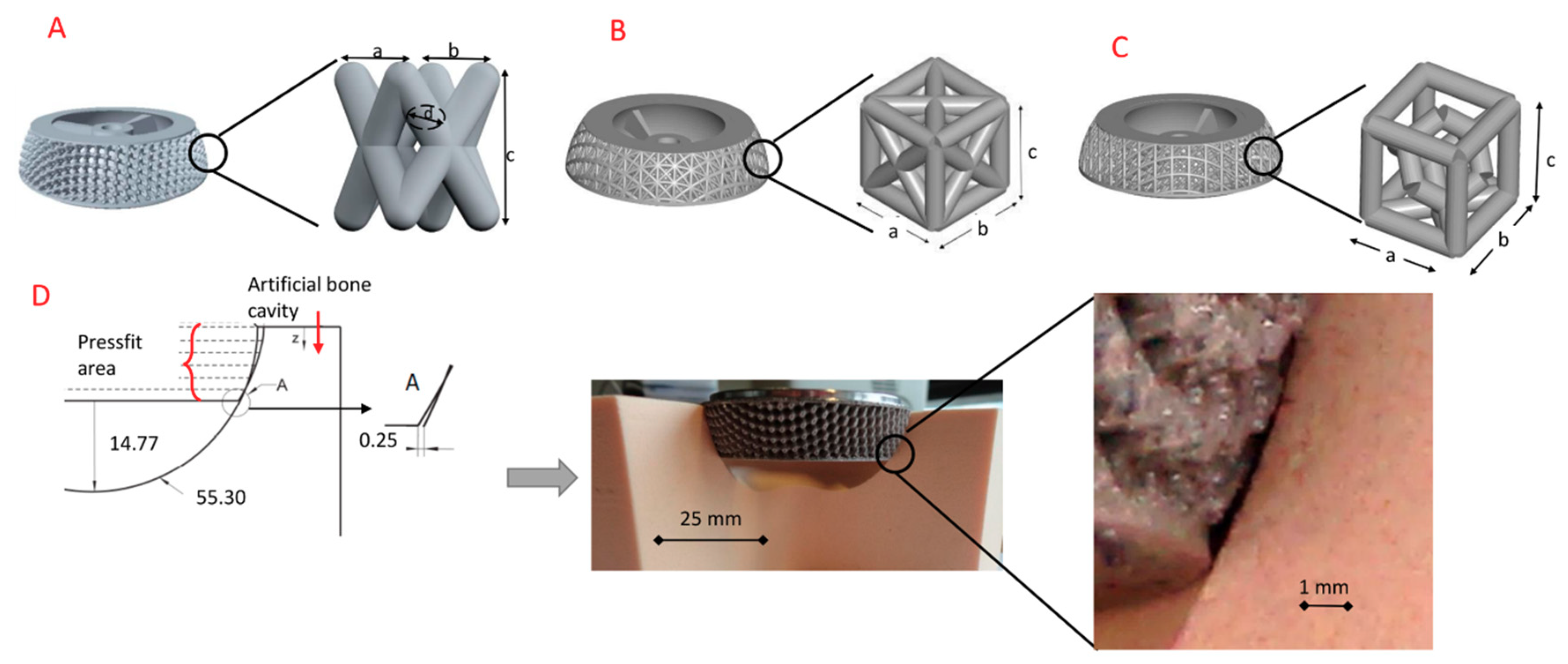
p = 0.0242). The differences between the combined open and twisted structures can mainly be explained by the existing differences in press-fit volume. The press-fit volumes of the combined (D4_08 = 0.91 cm3; D4_09 = 0.97 cm3) and the combined open structure with 0.77 cm3 clearly differ from the twisting structures (<0.54 cm3). However, this relationship is not identifiable in the twisting structures, since despite clear differences in the press-fit volume between the twisting structures, a significant difference could only be determined between the variants V3_08 and V4_10. It seems that in addition to the press-fit volume, other influencing factors such as the surface quality (roughness and manufacturing accuracy) of the struts of the structure and their dimensions (length, diameter, surface area) could play a role [55,59].
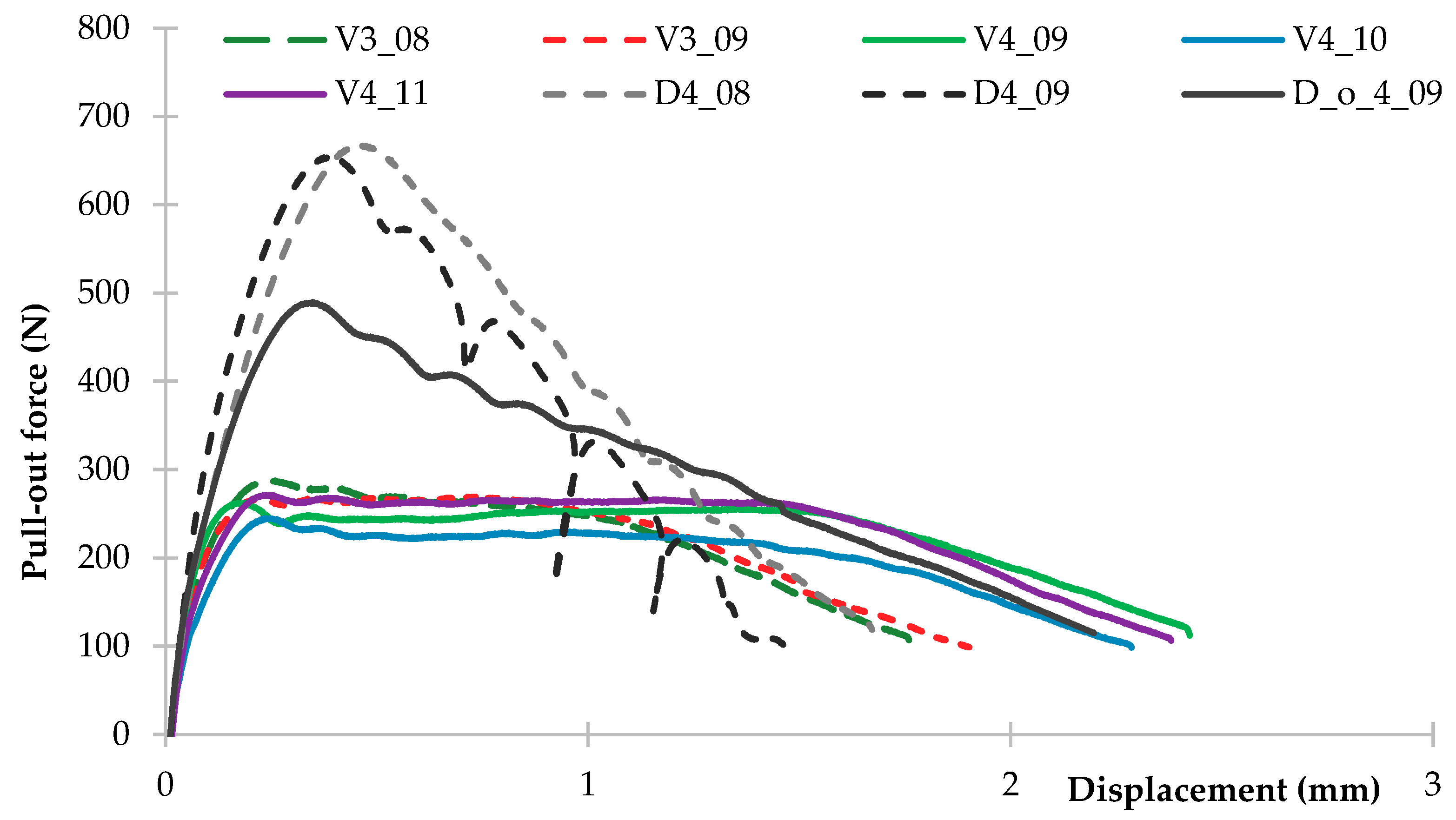
The pull-out behavior of the different cup models is shown in Figure 6. The representation of the force profiles over cup displacement in the artificial bone cavity additionally offers the possibility to evaluate the measured maximum force in relation to the reached cup displacement at that time. The curves show characteristic differences.
The curve for the cups with a combined structure differs clearly from the curves for the cups with a combined open or twisting structure. The most striking feature here is the cascading force decrease after a maximum force has been exceeded. This cascade is characterized in that a renewed force increase is determined after a drop in force. This course reflects the loosening and re-jamming of the cup in the artificial bone cavity. These cascades are most pronounced in version D4_09. This cascade development is also evident in the combined open structure version D4_08, though weaker. Apparently, this cascade is due to the larger space between the individual struts or the greater porosity. Here, the material of the artificial bone cavity has the possibility to fill more space. The necessary release from this room requires force again.
This cascade is characterized in that a renewed force increase is determined after a drop in force. This course reflects the loosening and re-jamming of the cup in the artificial bone cavity. These cascades are most pronounced in version D4_09. This cascade development is also evident in the combined open structure version D4_08, though weaker. Apparently, this cascade is due to the larger space between the individual struts or the greater porosity. Here, the material of the artificial bone cavity has the possibility to fill more space. The necessary release from this room requires force again.
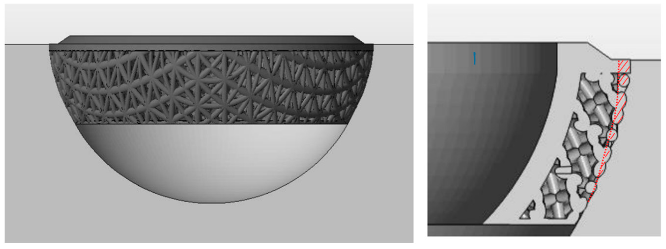
The number of cascades obviously results from the number of superficial, continuous struts (Figure 7—red lines). The maximum peak (and thus the first peak of force) results from overcoming the edge of the hip cup. The second to fifth peak results from the strut contours. Starting at the highest point of the continuous strut lines. The differences in cascade intensity of the cup variants are caused by the differences in the strut diameter. The strut with a rod diameter of 0.9 mm has a larger contact surface to the artificial bone bed. This requires more force to loosen from the artificial bone cavity. The differences between the open and closed variants (D_o_4_09 and D4_09) are due to the varying degrees of free space in the surface of the hip cups. More free space (D_o_4_09) requires less force than with the closed variant (D4_09).
The press-fit cups with the twisted structure show a completely different behavior. After reaching the force maximum, the corresponding force path continues at a uniform level of force. This applies to the twisted structure with a height of 3 mm as well as to the structure with a height of 4 mm. It is clearly shown here; however, that the versions in the 4 mm height maintain this level of force significantly longer. A weakening of the cup anchoring takes place here only after about 1.5 mm compared to about 1 mm in the variants with a height of 3 mm. Here, the cups with the structural elements whose individual elements have a height of 4 mm and an associated spacing of the bars of 2.83 mm, provide the artificial bone cavity material more space for anchoring than the variant of 3 mm height and a spacing of 2.12 mm. As a result, the force is maintained longer at one level.
In view of later desired ingrowth of the bone into the structural area as well as the formation of blood vessels, larger open areas have advantages over the smaller areas [22,25,60]. Here it is important to carefully observe the interaction of the geometric conditions (unit cell and macro-porosity) and the component properties influenced by the additive manufacturing process (e.g., roughness or micro-porosity, surface finish at intersections) [61,62,63].
While the diamond structures reach the maximum force required to pull out at approx. 0.6 to 0.7 mm, these values for the twisted structures are approx. 0.2 to 0.3 mm. The open combined structure shows a maximum at approx. 0.35 mm. In addition, it can be seen that the twisted version with a height of 3 mm as well as the combined structure D4_08 still require approximately 100 N after about 1.6 to 1.8 mm displacement for a further release.
In the case of the twisted versions with a height of 4 mm and the open combined structure, the cups have already experienced a displacement of approximately 2.5 mm at a force of 100 N. The progression curves of the press-fit cups are very similar. This value probably reflects the interaction between the artificial bone cavity and the surface of the additively manufactured cup.
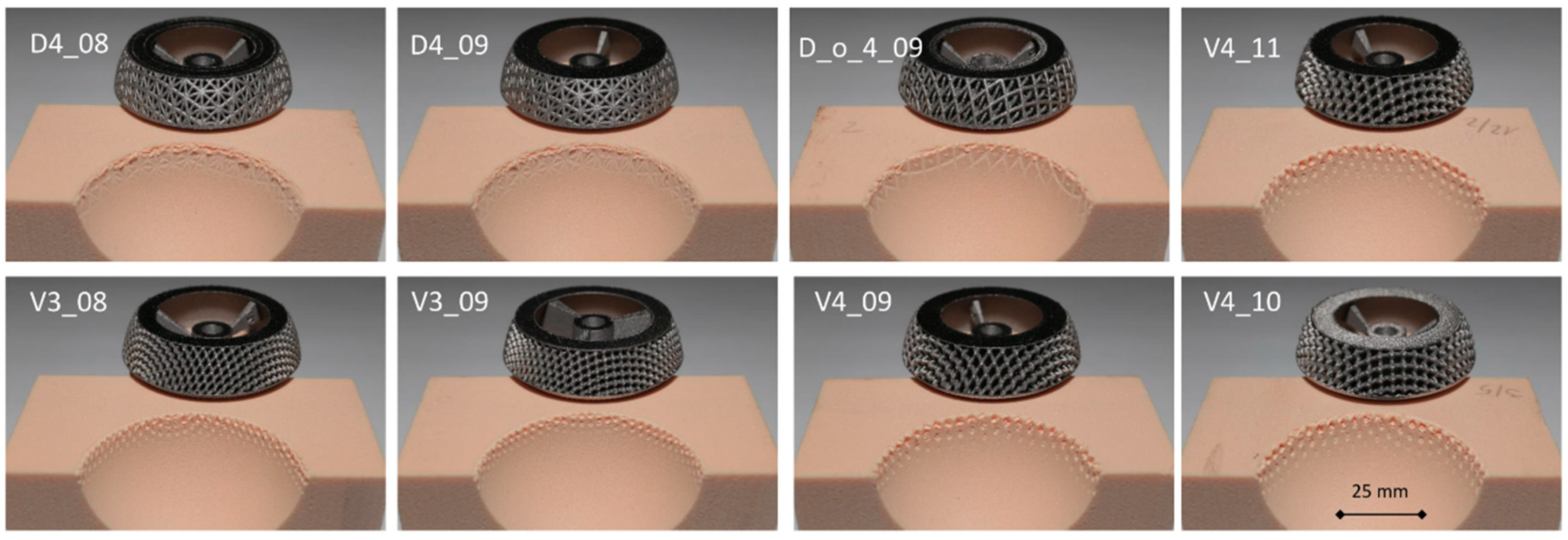
As can be seen from Figure 8, all cups leave clear traces of an impression on the entire circumference of the artificial bone bed. The evaluation of these traces using this visual assessment of the contact surface has been described, for example, by Le Cann et al. to characterize how the roughness of a cup affects primary stability [33].
All cups left distinct positioning traces in the press-fit region. The artificial bone cavity remained intact. The artificial bone cavities shown in Figure 8 exhibit clear marks of an anchorage. The damage patterns of the artificial bone cavity differ optically from each other.
All twisted versions show dot-like impressions in the cavity area. The cavity edges remain sharply intact. Differences caused by the different bar diameters (3 and 4 mm) and bar distances (2.83 and 2.12 mm) are optically present. With increasing bar diameter, the damage in the bone bed also increases. Variant V4_11 shows clearer and stronger traces than versions V4_10, V4_09, V3_08 and V3_09.
The combined structures (D4_08, D4_09) show rather flat impressions on the artificial bone cavity areas. The cavity edges tend to blur slightly, as a representation of slight material detachments. These detachments are much less pronounced in the diamond open structure.
The forces determined in the pull-out test and the traces in the bone bearing also allow the following conclusion to be drawn. The twisting structure already destroys the corresponding area in the bone bearing during the press fitting. Because of that, less force is required when pulling out of the bearing because the resistances against loosening are lower than with intact material. The combined structure, on the other hand, only damages the bone bearing when it is pulled out. Here, the resistance of predominantly intact material must be overcome. This leads to a higher power requirement.
In addition, the contacting of the structures with the bone bed takes place differently. The contact of the twisting structure is made punctually. The combined and combined open structure creates a two-dimensional contact to the surface of the bone bed. To overcome the press fit, more force is required for the two-dimensional contacts than for the punctual contacts.

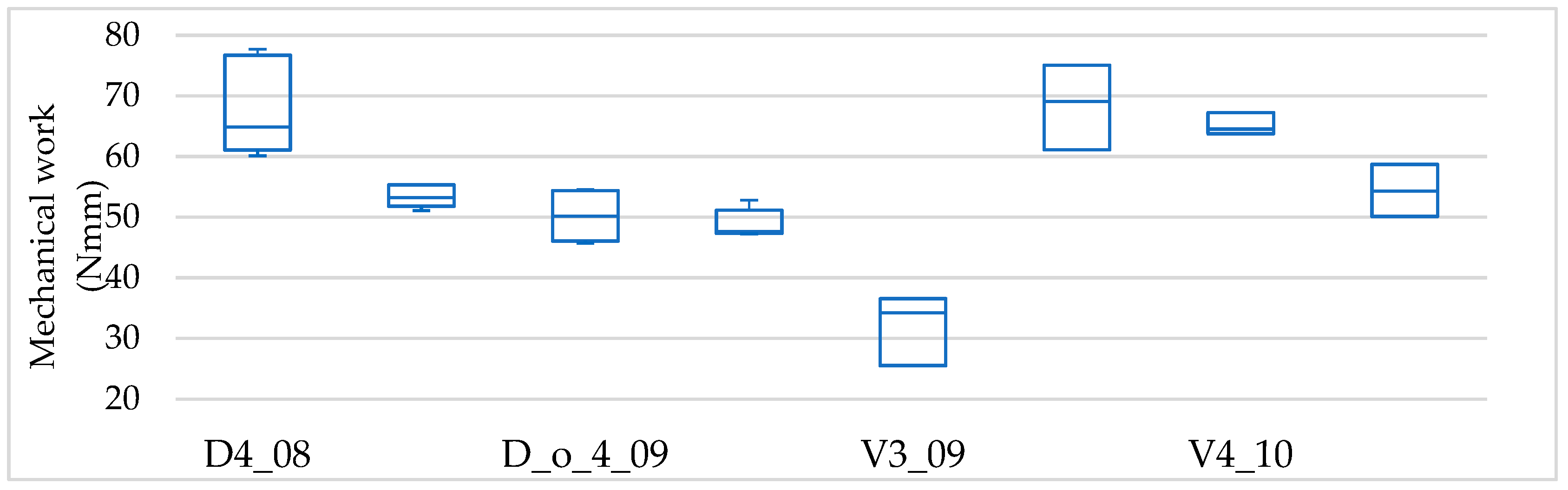
3.3. Lever-Out Moment

After being press-fitted into the artificial bone cavities, all cup models were levered out from the cavities to determine the lever-out moments as described in 0. The results are shown in Figure 9 and Table 5. The course of the forces required to lever out the cups over the displacement is shown in Figure 10.
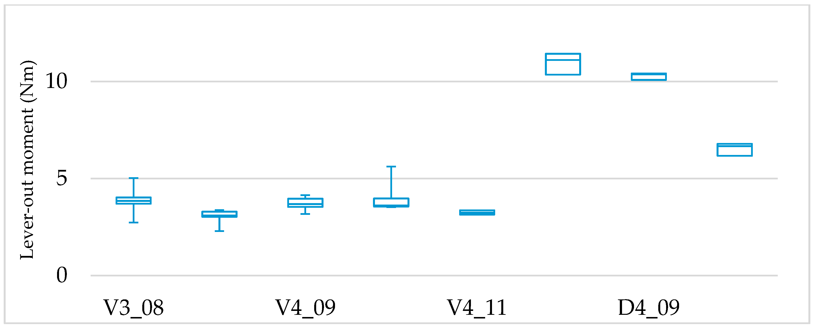
The influence of the applied structural elements on the behavior of the press-fit cups in the lever-out test can be clearly established on the basis of the experimentally determined lever-out moments. The best results were achieved by the combined structure (D4_08 = 10.9 Nm, D4_09 = 10.3 Nm), followed by the combined open structure (6.5 Nm) and the twisted structure (Max: V3_08 = 3.9 Nm; Min: V3_09 = 3.1 Nm).
By carrying out a statistical significance test using one-way Anova with Dunnett’s T3 post-hoc test (multiple comparisons) it is possible to describe the following relationships. The two combined structures do not differ significantly from each other. However, the combined open structure is significantly below the combined structure (D4_08 and D4_09 to D_o_4_09/p < 0.001).
The differences of the experimentally determined lever-out moments shown between the combined structures, the combined open structures and the twisted structures are significant in all cases (p < 0.001). For the twisted structures, only the version V3_08 deviates significantly from both version V3_09 (p = 0.04619) and version V4_11 (p = 0.04649). Similar to the pull-out tests, the differences between the combined and the combined open structures to the twisted structures can be explained by the existing differences in press-fit volume. The differences between the structure V3_08 and V3_09 and V4_11 also result from the differences in the press-fit volumes (V3_08 = 0.54 cm3; V3_09 = 0.32 cm3; V4_11 = 0.25 cm3). The fact that variant V4_09 does not deviate significantly from variant V3_8 despite a lower press-fit volume (0.3 cm3) is additional evidence that other factors are notoriously influencing the anchoring strength.
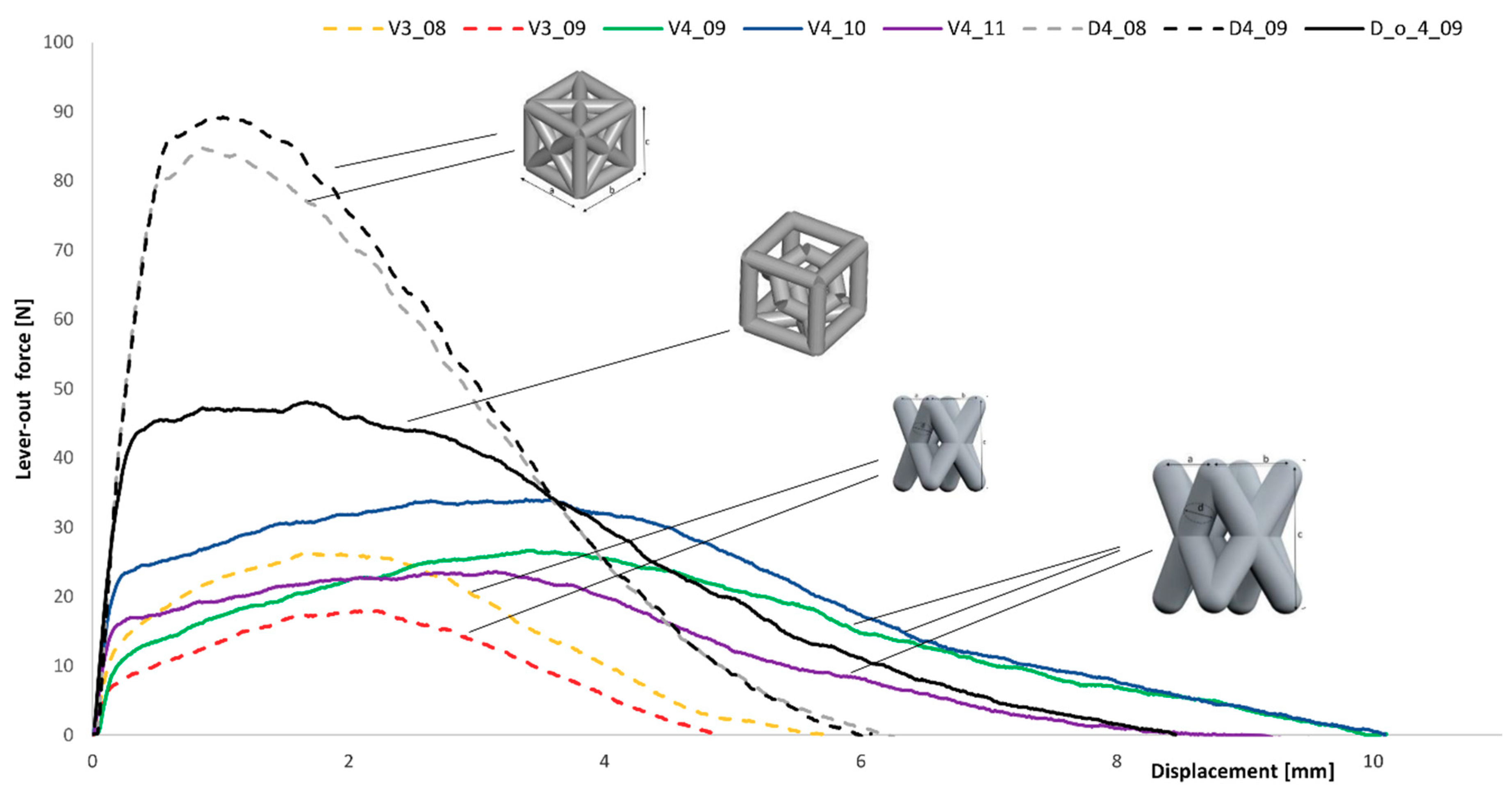
The lever-out behavior of the tested cup models is shown in Figure 10. All additively manufactured cups show curves which are characteristic for the structural elements used.
All models were preloaded with an initial moment of 0.62 Nm by the self-weight of the test setup. The representation of lever-out forces over displacement displays for the combined structure a maximum lever-out force (mean values: D4_08 = 90.3 N; D4_09 = 85 N) at a displacement of approx. 1 mm and then a decrease of the moment up to a displacement of 6 mm. The combined open structure reaches a lever-out force maximum (mean value: 51.6 N) after approx. 1.8 mm. This cup variant reduces the force to zero after a displacement of about 8.3 mm. The twisted structures show differences depending on the size of the structure. The twisted structures with dimensions of 3 mm height reach a lever-out force maximum (mean values: V3_08 = 29 N; V3_09 = 22 N) after about 1.8 to 2.2 mm. The twisted structures with dimensions of 4 mm height reach force maximums (mean values: V4_09 = 27.1 N; V4_10 = 27.5 N; V4_11 = 23.2 N) after about 3.5 to 3.7 mm. The force reduction continues in the V3-versions up to a displacement of approx. 4.8 to 5.8 mm. The V4 versions run to zero at about 9 to 10.5 mm.
Similar to the pull-out tests, it can be seen that, following a steep rise, the cups with the combined structure show a continuous force drop after reaching a lever-out force maximum. The combined open structure and the twisted structures behave differently. Here the maximum force is only reached after passing through a plateau phase. This plateau phase is much longer for the V4-variants than for the V3-variants.
This functional difference is related to the geometric design of the individual structures. As shown in Table 1, the combined structures are structures that produce a relatively uniformly shaped surface whose interstices engage only weakly in the bone bed. Here the press-fit is in the foreground.
In the combined open structure and the twisted structures, the shaped surface of the cups is much more open. These structures engage more clearly in the artificial bone stock. The differences between the V3 and V4 variants are due to the geometric dimensions of the individual rods. The larger-sized rods of the V4 variant have larger gaps than the V3-variants (V4-2.83 mm and V3-2.12 mm). Thus, a hooking of the structural elements in the bone cavity in the V4-variant is possible across a longer distance than in the V3 variant.
This leads to differences in the height of the moments determined due to the structure design. In addition, it becomes clear that the twisted structures in the artificial bone bed produce deeper punctual impressions. During the lever-out test, the struts move along these impressions. This behavior is recognizable for all twisted structure variants by traces between the punctual impressions. The illustrations of the bone beds after the pull-out test (Figure 8) do not show these traces. Therefore, due to the already damaged surface, less force is required to lever-out. The twisted structures thereby show overall lower moments than the combined and combined open structure due to the different nature of the unit cell.
A larger structural design is helpful in terms of the positive effects for bone ingrowth [25]. In addition to good primary stability, the bone-like properties of the load-bearing structural layer are an essential prerequisite for good secondary stability of the implant [64]. Secondary stability is essentially characterized by the ability of bone to grow onto the implant surface and thereby firmly anchor the implant. The use of open-pore structures enlarges the implant surface and thus improves the prerequisite for the formation of sufficiently high secondary stability. In addition, a high primary anchoring strength is the prerequisite for creating a sufficiently high secondary stiffness, since only then is sufficient growth of the bone on the surface possible. Only if a load transfer via the implant into the surrounding bone is possible without stress-shielding can a successful use of the implants be ensured. With regard to the geometric selection of structural elements, this circumstance must be taken into account [65]. The combined structures, which are more direction-independent in their properties, show slight advantages here [52,66].
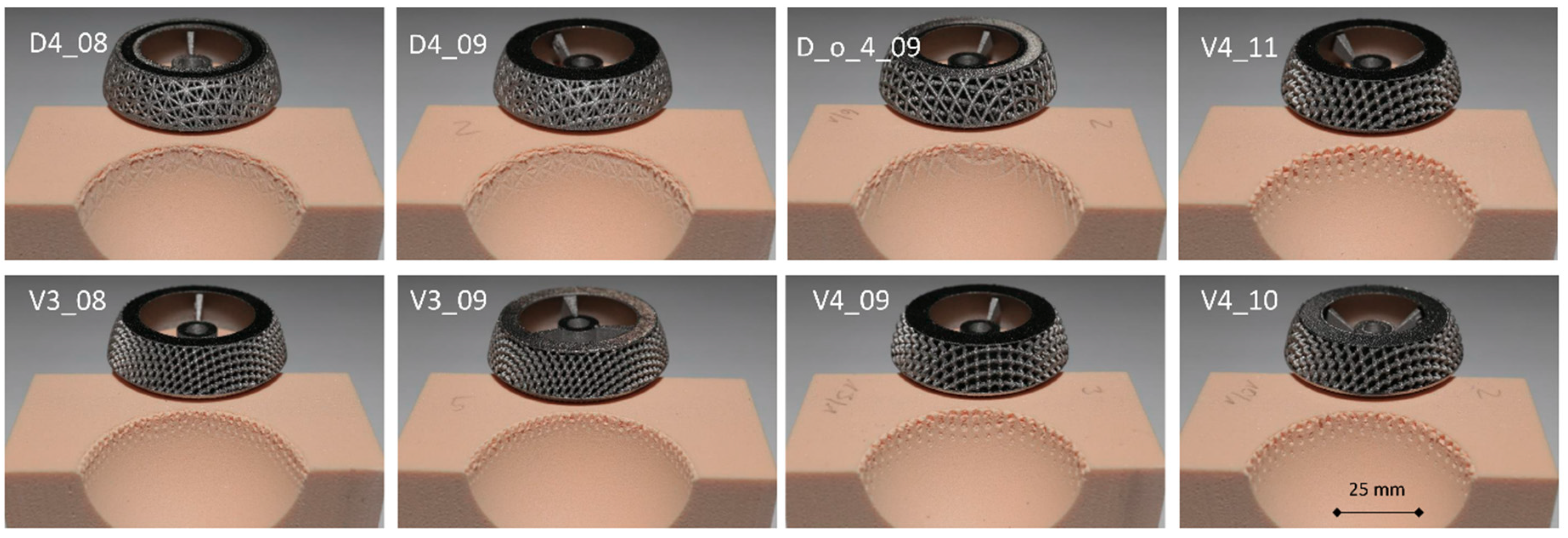
The artificial bone cavities show distinct traces left by the lever-out of the cups. In the following Figure 11 the cup models are shown with representative examples of the artificial bone cavity. The artificial bone cavity is intact despite clear traces of anchoring. The damage patterns of the bone cavities differ optically from each other, as in the case of the pull-out experiments. The twisted versions show, as expected, punctually impressions in the bone cavities. The edge of the cavity remains sharp. The different strut diameters and spaces of the struts in the structure produce visually recognizable representative patterns (dot-like impressions). The combined structures leave flat traces on the bone cavities. The edge of the bone cavities tends to blur slightly, as a representation of slight material detachments. These detachments are significantly less pronounced in the combined open structure.
The use of an artificial bone cavity has a positive effect on the characterization of primary stability. This speaks in favor of the experimental results determined here since possible property variations, as they occur in the use of cadaveric models, have been omitted. Goldman et al. compared the effect of component surface roughness at the bone implant interface and the quality of the bone on initial press-fit stability [67]. They found no significant differences between the bending moment at 150 m for two kind of press-fit cups with different coefficients of friction. They made clear in the discussion that the results from the use of the cadaveric models represent a realistic representation of surgical interventions, but are also associated with corresponding scatter of the results. For the purpose of this study, which is to evaluate structurally differently designed press-fit cups, the artificial bone bed is the better choice. The uniform mechanical properties of the artificial bone bed provide a much better basis for a comparative consideration of the different cup designs.

3.4. Lever-Out Momentmechanical Work

The lever-out work shown in Figure 12 illustrates the individual force differences required to loosen the cups from the artificial bone cavities. The moment of relaxation thus represents the beginning of the failure.
The best results were achieved with the cup versions V4_10 (69.9 Nmm), D4_08 (68.8 Nmm) and V4_09 (66.9 Nmm), followed by versions V4_11 (54.8 Nmm), D4_09 (53.1 Nmm) and D_o_4_09 (52.5 Nmm). Much less work was afforded for the loosening of versions V3_08 (48 Nmm) and V3_09 (32 Nmm).
After carrying out a statistical significance test (results Table 6) using one-way Anova with Dunnett’s T3 post-hoc test (multiple comparisons), the following coherences become clear. The combined structures D4_08 (p = 0.04296) and D4_09 (p = 0.01733) deviate significantly from version V3_09. The twisted structure V3_09 deviates significantly from versions V4_09 (p = 0.01595), V4_10 (p = 0.03089) and V4_11 (p = 0.01335).
In the pull-out test (determined force) and lever-out test (determined moment), the twisted structures perform worse in the evaluation than the combined and combined open structure. However, in the mechanical work determined, the twisted structures with a strut diameter of 4 mm achieve equivalent results here. One reason seems to be that the struts pressed into the artificial bone bed material move along the entire lever-out process in the bone bed material. This means that permanent work has to be done to move the cup further out of the bone bed. This is clearly demonstrated by the curves in Figure 10. This is also supported by the fact that the variants V4_10 and V4_09 achieve the highest values in the work determined. These variants also have the largest gaps between the struts, followed by version V4_11. A larger gap also has a higher proportion of material in the gap than smaller gaps. More material at the same time means more work to overcome the resistance. In total, this means that the work performed for the cup variants D4_08 and V4_09 and V4_10 is comparable. This fact is supported by the results of the cup variant V3_09, which has the lowest porosity (58.8 %) compared to all the other variants tested.

3.5. Correlations—Lever-Out Moment and Pull-Out Force Versus Volume of the Press-Fit Area

Anchoring strength is significantly influenced by the structure used, with its open-porous design characterizing the area that represents the press-fit. When looking at the volume characteristic of each cup variant in relation to the pull-out force or the lever-out moment (Figure 13), it can be seen that the pull-out force and the lever-out moment could be determined by a direct functional relationship, which can be described using a non-linear regression. An exponential function was found which describes the results of the experimental investigations very well. The curve clearly shows that the pull-out forces as well as the lever-out moments are relatively uniform up to a press-fit volume of 0.39 cm3, followed by a strong increase towards higher press-fit volumes. At high volumes (>0.9 cm3), the results are very similar for the pull-out forces as well as for the lever-out moments.
Both dimensions show an exponential functional relation to the press-fit volume, which is reflected by strong regression coefficients (R2 = 0.9342 for pull-out force, R2 = 0.9133 for lever-out moment). This makes it clear that an increase in anchoring strength can be achieved with increasing press-fit volume.
Although the press-fit volume used for this reference does not represent the full volume that actually penetrates the area of the artificial bone, it does directly represent the volume that creates the press-fit.
The determined functional relationships as well as the experimentally obtained measurement results provide a good basis for the selection of appropriate structural elements for the final development of press-fit acetabular cups, which ensure an increase in primary anchoring strength. In particular, the geometric design of the structural elements can thus be used in a targeted manner in conjunction with the mechanical properties and porosity [52,66,68,69,70]. Also, the determined functional relationships prove that the influence of the volume responsible for the actual press-fit is significantly greater than the porosity. However, since porosity is a measure relevant to secondary anchoring strength, it must not be disregarded.
Structured press-fit cups present an interesting solution, especially with regard to strong pelvic defects (D’Antonio type II). Due to the geometric freedom in structure design and possible size variations, these types of press-fit cups could offer advantages over non-structured cups in anchoring strength [71].
The characterization of the structurally differently designed press-fit cups with two test methods as well as the evaluation of the results in relation to different influencing factors makes a distinctive estimation of the types of cups possible. While the evaluation of anchoring strength with only one procedure or from one aspect is being discussed controversially, a good summary can be made in this study [67]. Several factors, such as material and surface structure (e.g., bead or wire) have been shown to be responsible for bone ingrowth [72]. The press-fit cups used here in this study have almost identical properties so that these can be neglected in the consideration.
The characterization of the cup variants based on the experimentally determined results offers the possibility to capture significant influences and thus show differences. The functional relationships also offer the opportunity to actively intervene in the constructive process and influence the structure design based on the results.

4. Conclusions

In this study, acetabular press-fit cups with a porous, load-bearing structural layer were examined for primary stability. The press-fit cup used was a design developed and evaluated in a previous study.
The porous, load-bearing structural layer was formed from geometrically differently designed unit cells. The preparation was carried out by means of selective laser melting of TiAl6V4. As an artificial bone cavity a PU foam was used, which was characterized experimentally in terms of mechanical properties.
The results show significant differences in the experimentally determined pull-out force, lever-out moment and lever-out-work results. The best results in pull-out and lever-out moments are achieved by the press-fit cups made in the combined structure (denoted D4_08 and D4_09). When looking at the work required to lever out the press-fit cups, it is noticeable that the press-fit cups designated as D4_08, V4_09 and V4_10 achieved the best results.
Overall, it becomes clear that the results for the evaluation of primary stability are related to the geometry used (unit cell), the dimensions of the unit cell, and the volume and porosity which are responsible for the press fit. Corresponding functional relationships could be determined.
The results of the work provide an excellent starting point for the development of press-fit acetabular cups with increased primary stability as a basis for high secondary stability.

Author Contributions

We point out that all authors were fully involved in the study and in preparing the manuscript. V.W. and C.S. designed the study. V.W. generated the CAD samples with support of C.B. and was involved in the manufacturing process of the scaffolds. V.W. and C.S. performed the experiments, analyzed the data with support of C.B. and wrote the initial manuscript. H.H. and R.B. organized the research funding. All authors ensured the accuracy of the data and the analyses and reviewed the manuscript in its current state.

Funding

This research was funded by Federal Ministry of Education and Research grant number 03FH005IX5.

Conflicts of Interest

The authors declare no conflict of interest.

References

  1. Harrison, N.; Field, J.R.; Quondamatteo, F.; Curtin, W.; McHugh, P.E.; Mc Donnell, P. Preclinical trial of a novel surface architecture for improved primary fixation of cementless orthopaedic implants. Clin. Biomech. 2014, 29, 861–868. [Google Scholar] [CrossRef] [PubMed]
  2. Levine, B. A new era in porous metals: Applications in orthopaedics. Adv. Eng. Mater. 2008, 10, 788–792. [Google Scholar] [CrossRef]
  3. Murr, L.E. Open-cellular metal implant design and fabrication for biomechanical compatibility with bone using electron beam melting. J. Mech. Behav. Biomed. Mater. 2017, 76, 164–177. [Google Scholar] [CrossRef] [PubMed]
  4. Sing, S.L.; An, J.; Yeong, W.Y.; Wiria, F.E. Laser and electron-beam powder-bed additive manufacturing of metallic implants: A review on processes, materials and designs. J. Orthop. Res. 2016, 34, 369–385. [Google Scholar] [CrossRef] [PubMed]
  5. Geetha, M.; Singh, A.K.; Asokamani, R.; Gogia, A.K. Ti based biomaterials, the ultimate choice for orthopaedic implants—A review. Prog. Mater. Sci. 2009, 54, 397–425. [Google Scholar] [CrossRef]
  6. Tan, X.P.; Tan, Y.J.; Chow, C.S.L.; Tor, S.B.; Yeong, W.Y. Metallic powder-bed based 3D printing of cellular scaffolds for orthopaedic implants: A state-of-the-art review on manufacturing, topological design, mechanical properties and biocompatibility. Mater. Sci. Eng. C 2017, 76, 1328–1343. [Google Scholar] [CrossRef] [PubMed]
  7. Schulze, C.; Weinmann, M.; Schweigel, C.; Keßler, O.; Bader, R. Mechanical Properties of a Newly Additive Manufactured Implant Material Based on Ti-42Nb. Materials 2018, 11, 124. [Google Scholar] [CrossRef] [PubMed]
  8. Murr, L.E.; Amato, K.N.; Li, S.J.; Tian, Y.X.; Cheng, X.Y.; Gaytan, S.M.; Martinez, E.; Shindo, P.W.; Medina, F.; Wicker, R.B. Microstructure and mechanical properties of open-cellular biomaterials prototypes for total knee replacement implants fabricated by electron beam melting. J. Mech. Behav. Biomed. Mater. 2011, 4, 1396–1411. [Google Scholar] [CrossRef] [PubMed]
  9. Do Prado, R.F.; De Oliveira, F.S.; Nascimento, R.D.; De Vasconcellos, L.M.R.; Carvalho, Y.R.; Cairo, C.A.A. Osteoblast response to porous titanium and biomimetic surface: In vitro analysis. Mater. Sci. Eng. C 2015, 52, 194–203. [Google Scholar] [CrossRef] [PubMed]
  10. Wang, X.; Zhou, S.; Xu, W.; Leary, M.; Choong, P.; Qian, M.; Brandt, M.; Xie, Y.M.; Xu, S. Topological design and additive manufacturing of porous metals for bone scaffolds and orthopaedic implants: A review. Biomaterials 2016, 83, 14. [Google Scholar] [CrossRef] [PubMed]
  11. Limmahakhun, S.; Oloyede, A.; Sitthiseripratip, K.; Xiao, Y.; Yan, C. Stiffness and strength tailoring of cobalt chromium graded cellular structures for stress-shielding reduction. Mater. Des. 2017, 114, 633–641. [Google Scholar] [CrossRef]
  12. Simoneau, C.; Terriault, P.; Jetté, B.; Dumas, M.; Brailovski, V. Development of a porous metallic femoral stem: Design, manufacturing, simulation and mechanical testing. Mater. Des. 2017, 114, 546–556. [Google Scholar] [CrossRef]
  13. Kumar, A.; Nune, K.C.; Murr, L.E.; Misra, R.D.K. Biocompatibility and mechanical behaviour of three-dimensional scaffolds for biomedical devices: Process-structure-property paradigm. Int. Mater. Rev. 2016, 61, 20–45. [Google Scholar] [CrossRef]
  14. Harrison, N.; McHugh, P.E.; Curtin, W.; Mc Donnell, P. Micromotion and friction evaluation of a novel surface architecture for improved primary fixation of cementless orthopaedic implants. J. Mech. Behav. Biomed. Mater. 2013, 21, 37–46. [Google Scholar] [CrossRef] [PubMed]
  15. Jetté, B.; Brailovski, V.; Dumas, M.; Simoneau, C.; Terriault, P. Femoral stem incorporating a diamond cubic lattice structure: Design, manufacture and testing. J. Mech. Behav. Biomed. Mater. 2018, 77, 58–72. [Google Scholar] [CrossRef] [PubMed]
  16. Marin, E.; Fusi, S.; Pressacco, M.; Paussa, L.; Fedrizzi, L. Characterization of cellular solids in Ti6Al4V for orthopaedic implant applications: Trabecular titanium. J. Mech. Behav. Biomed. Mater. 2010, 3, 373–381. [Google Scholar] [CrossRef] [PubMed]
  17. Le Guéhennec, L.; Soueidan, A.; Layrolle, P.; Amouriq, Y. Surface treatments of titanium dental implants for rapid osseointegration. Dent. Mater. 2007, 23, 844–854. [Google Scholar] [CrossRef] [PubMed]
  18. Khanna, R.; Kokubo, T.; Matsushita, T.; Nomura, Y.; Nose, N.; Oomori, Y.; Yoshida, T.; Wakita, K.; Takadama, H. Novel artificial hip joint: A layer of alumina on Ti-6Al-4V alloy formed by micro-arc oxidation. Mater. Sci. Eng. C 2015, 55, 393–400. [Google Scholar] [CrossRef] [PubMed]
  19. Ramsden, J.J.; Allen, D.M.; Stephenson, D.J.; Alcock, J.R.; Peggs, G.N.; Fuller, G.; Goch, G. The design and manufacture of biomedical surface. CIRP Ann. Manuf. Technol. 2007, 56, 687–711. [Google Scholar] [CrossRef]
  20. Emmelmann, C.; Scheinemann, P.; Munsch, M.; Seyda, V. Laser additive manufacturing of modified implant surfaces with osseointegrative characteristics. Phys. Procedia 2011, 12, 375–384. [Google Scholar] [CrossRef]
  21. Paris, M.; Götz, A.; Hettrich, I.; Bidan, C.M.; Dunlop, J.W.C.; Razi, H.; Zizak, I.; Hutmacher, D.W.; Fratzl, P.; Duda, G.N.; et al. Scaffold curvature-mediated novel biomineralization process originates a continuous soft tissue-to-bone interface. Acta Biomater. 2017, 60, 64–80. [Google Scholar] [CrossRef] [PubMed]
  22. Wang, Z.; Wang, C.; Li, C.; Qin, Y.; Zhong, L.; Chen, B.; Li, Z.; Liu, H.; Chang, F.; Wang, J. Analysis of factors influencing bone ingrowth into three-dimensional printed porous metal scaffolds: A review. J. Alloys Compd. 2017, 717, 271–285. [Google Scholar] [CrossRef]
  23. Schouman, T.; Schmitt, M.; Adam, C.; Dubois, G.; Rouch, P. Influence of the overall stiffness of a load-bearing porous titanium implant on bone ingrowth in critical-size mandibular bone defects in sheep. J. Mech. Behav. Biomed. Mater. 2016, 59, 484–496. [Google Scholar] [CrossRef] [PubMed]
  24. de Wild, M.; Zimmermann, S.; Rüegg, J.; Schumacher, R.; Fleischmann, T.; Ghayor, C.; Weber, F.E. Influence of microarchitecture on osteoconduction and mechanics of porous titanium Scaffolds generated by selective laser melting. 3D Print. Addit. Manuf. 2016, 3, 142–151. [Google Scholar] [CrossRef]
  25. Taniguchi, N.; Fujibayashi, S.; Takemoto, M.; Sasaki, K.; Otsuki, B. Effect of pore size on bone ingrowth into porous titanium implants. Mater. Sci. Eng. C 2016, 59, 690–701. [Google Scholar] [CrossRef] [PubMed]
  26. Jetté, B.; Brailovski, V.; Simoneau, C.; Dumas, M.; Terriault, P. Development and in vitro validation of a simplified numerical model for the design of a biomimetic femoral stem. J. Mech. Behav. Biomed. Mater. 2017, 77, 539–550. [Google Scholar] [CrossRef] [PubMed]
  27. Bellini, C.M.; Galbusera, F.; Ceroni, R.G.; Raimondi, M.T. Loss in mechanical contact of cementless acetabular prostheses due to post-operative weight bearing: A biomechanical model. Med. Eng. Phys. 2007, 29, 175–181. [Google Scholar] [CrossRef] [PubMed]
  28. Souffrant, R.; Zietz, C.; Fritsche, A.; Kluess, D.; Mittelmeier, W.; Bader, R. Advanced material modelling in numerical simulation of primary acetabular press-fit cup stability. Comput. Methods Biomech. Biomed. Engin. 2012, 15, 787–793. [Google Scholar] [CrossRef] [PubMed]
  29. Small, S.R.; Berend, M.E.; Howard, L.A.; Rogge, R.D.; Buckley, C.A.; Ritter, M.A. High initial stability in porous titanium acetabular cups: A biomechanical study. J. Arthroplast. 2013, 28, 510–516. [Google Scholar] [CrossRef] [PubMed]
  30. Udofia, I.; Liu, F.; Jin, Z.; Roberts, P.; Grigoris, P. The initial stability and contact mechanics of a press-fit resurfacing arthroplasty of the hip. J. Bone Jt. Surg. Br. 2007, 89, 549–556. [Google Scholar] [CrossRef] [PubMed] [Green Version]
  31. Chang, J.-D.; Kim, T.-Y.; Rao, M.B.; Lee, S.-S.; Kim, I.-S. Revision total hip arthroplasty using a tapered, press-fit cementless revision stem in elderly patients. J. Arthroplast. 2011, 26, 1045–1049. [Google Scholar] [CrossRef] [PubMed]
  32. Chanlalit, C.; Fitzsimmons, J.S.; Shukla, D.R.; An, K.-N.; O’Driscoll, S.W. Micromotion of plasma spray versus grit-blasted radial head prosthetic stem surfaces. J. Shoulder Elb. Surg. 2011, 20, 717–722. [Google Scholar] [CrossRef] [PubMed]
  33. Le Cann, S.; Galland, A.; Rosa, B.; Le Corroller, T.; Pithioux, M.; Argenson, J.N.; Chabrand, P.; Parratte, S. Does surface roughness influence the primary stability of acetabular cups? A numerical and experimental biomechanical evaluation. Med. Eng. Phys. 2014, 36, 1185–1190. [Google Scholar] [CrossRef] [PubMed]
  34. Goriainov, V.; Jones, A.; Briscoe, A.; New, A.; Dunlop, D. Do the cup surface properties influence the initial stability? J. Arthroplast. 2014, 29, 757–762. [Google Scholar] [CrossRef] [PubMed]
  35. Gebert, A.; Peters, J.; Bishop, N.E.; Westphal, F.; Morlock, M.M. Influence of press-fit parameters on the primary stability of uncemented femoral resurfacing implants. Med. Eng. Phys. 2009, 31, 160–164. [Google Scholar] [CrossRef] [PubMed]
  36. Ries, M.D.; Harbaugh, M.; Shea, J.; Lambert, R. Effect of cementless acetabular cup geometry on strain distribution and press-fit stability. J. Arthroplast. 1997, 12, 207–212. [Google Scholar] [CrossRef]
  37. Adler, E.; Stuchin, S.A.; Kummer, F.J. Stability of press-fit acetabular cups. J. Arthroplast. 1992, 7, 295–301. [Google Scholar] [CrossRef]
  38. Macdonald, W.; Carlsson, L.V.; Charnley, G.J.; Jacobsson, C.M. Press-fit acetabular cup fixation: Principles and testing. Proc. Inst. Mech. Eng. Part H J. Eng. Med. 1999, 213, 33–39. [Google Scholar] [CrossRef] [PubMed] [Green Version]
  39. Morlock, M.; Götzen, N.; Sellenschloh, K. Bestimmung der Primärstabilität von künstlichen Hüftpfannen. In DVM Bericht 314—Eigenschaften und Prüftechniken mechanisch Beanspruchter Implantate; DVM: Berlin, Germany, 2002; pp. 221–229. [Google Scholar]
  40. Toossi, N.; Adeli, B.; Timperley, A.J.; Haddad, F.S.; Maltenfort, M.; Parvizi, J. Acetabular components in total hip arthroplasty: Is there evidence that cementless fixation is better? J. Bone Jt. Surg. 2013, 95, 168–174. [Google Scholar] [CrossRef] [PubMed]
  41. Roth, A.; Winzer, T.; Sander, K.; Anders, J.O.; Venbrocks, R.-A. Press fit fixation of cementless cups: How much stability do we need indeed? Arch. Orthop. Trauma Surg. 2006, 126, 77–81. [Google Scholar] [CrossRef] [PubMed]
  42. Tabata, T.; Kaku, N.; Hara, K.; Tsumura, H. Initial stability of cementless acetabular cups: Press-fit and screw fixation interaction—An in vitro biomechanical study. Eur. J. Orthop. Surg. Traumatol. 2015, 25, 497–502. [Google Scholar] [CrossRef] [PubMed]
  43. Takao, M.; Nakamura, N.; Ohzono, K.; Sakai, T.; Nishii, T.; Sugano, N. The results of a press-fit-only technique for acetabular fixation in hip dysplasia. J. Arthroplast. 2011, 26, 562–568. [Google Scholar] [CrossRef] [PubMed]
  44. Amirouche, F.; Solitro, G.; Broviak, S.; Gonzalez, M.; Goldstein, W.; Barmada, R. Factors influencing initial cup stability in total hip arthroplasty. Clin. Biomech. 2014, 29, 1177–1185. [Google Scholar] [CrossRef] [PubMed]
  45. Clarke, H.J.; Jinnah, R.H.; Warden, K.E.; Cox, Q.G.; Curtis, M.J. Evaluation of acetabular stability in uncemented prostheses. J. Arthroplast. 1991, 6, 335–340. [Google Scholar] [CrossRef]
  46. Klanke, J.; Partenheimer, A.; Westermann, K. Biomechanical qualities of threaded acetabular cups. Int. Orthop. 2002, 26, 278–282. [Google Scholar] [CrossRef] [PubMed] [Green Version]
  47. Baleani, M.; Fognani, R.; Toni, A. Initial stability of a cementless acetabular cup design: Experimental investigation on the effect of adding fins to the rim of the cup. Artif. Organs. 2001, 25, 664–669. [Google Scholar] [CrossRef] [PubMed]
  48. Olory, B.; Havet, E.; Gabrion, A.; Vernois, J.; Mertl, P. Comparative in vitro assessment of the primay stbility of cementless press-fit acetabular cups. Acta Orthop. Belg. 2004, 70, 31–37. [Google Scholar] [PubMed]
  49. Fritsche, A.; Zietz, C.; Teufel, S.; Kolp, W.; Tokar, I.; Mauch, C.; Mittelmeier, W.; Bader, R. In-vitro and in-vivo investigations of the impaction and pull-out behavior of metal-backed acetabular cups. Br. Ed. Soc. Bone Jt. Surg. 2011, 93, 406. [Google Scholar]
  50. Weißmann, V.; Boss, C.; Bader, R.; Hansmann, H. A novel approach to determine primary stability of acetabular press-fit cups. J. Mech. Behav. Biomed. Mater. 2018, 80, 1–10. [Google Scholar] [CrossRef] [PubMed]
  51. Markhoff, J.; Wieding, J.; Weissmann, V.; Pasold, J.A.; Jonitz-Heincke, R. Bader, Influence of different three-dimensional open porous titanium scaffold designs on human osteoblasts behavior in static and dynamic cell investigations. Materials 2015, 8, 5490–5507. [Google Scholar] [CrossRef] [PubMed]
  52. Weißmann, V.; Bader, R.; Hansmann, H.; Laufer, N. Influence of the structural orientation on the mechanical properties of selective laser melted Ti6Al4V open-porous scaffolds. Mater. Des. 2016, 95, 188–197. [Google Scholar] [CrossRef]
  53. Weißmann, V.; Wieding, J.; Hansmann, H.; Laufer, N.; Wolf, A.; Bader, R. Specific yielding of selective laser-melted Ti6Al4V open-porous scaffolds as a function of unit cell design and dimensions. Metals 2016, 6, 166. [Google Scholar] [CrossRef]
  54. Weißmann, V.; Hansmann, H.; Bader, R.; Laufer, N. Influence of the Structural Orientation on the Mechanical Properties of Selective Laser Melted TiAL6V4 Open-Porous Scaffold. In Proceedings of the 13th Rapid Tech Conference Erfurt, Erfurt, Germany, 14–16 June 2016. [Google Scholar]
  55. Fox, J.C.; Moylan, S.P.; Lane, B.M. Effect of process parameters on the surface roughness of overhanging structures in laser powder bed fusion additive manufacturing. Procedia CIRP 2016, 45, 131–134. [Google Scholar] [CrossRef]
  56. Rashed, M.G.; Ashraf, M.; Mines, R.A.W.; Hazell, P.J. Metallic microlattice materials: A current state of the art on manufacturing, mechanical properties and applications. Mater. Des. 2016, 95, 518–533. [Google Scholar] [CrossRef]
  57. Suard, M.; Martin, G.; Lhuissier, P.; Dendievel, R.; Vignat, F.; Blandin, J.J.; Villeneuve, F. Mechanical equivalent diameter of single struts for the stiffness prediction of lattice structures produced by Electron Beam Melting. Addit. Manuf. 2015, 8, 124–131. [Google Scholar] [CrossRef]
  58. Weißmann, V.; Drescher, P.; Bader, R.; Seitz, H.; Hansmann, H.; Laufer, N. Comparison of single Ti6Al4V struts made using selective laser melting and electron beam melting subject to part orientation. Metals 2017, 7, 91. [Google Scholar] [CrossRef]
  59. Triantaphyllou, A.; Giusca, C.L.; Macaulay, G.D.; Roerig, F.; Hoebel, M.; Leach, R.K.; Tomita, B.; Milne, K.A. Surface texture measurement for additive manufacturing. Surf. Topogr. Metrol. Prop. 2015, 3, 024002. [Google Scholar] [CrossRef] [Green Version]
  60. Frosch, K.; Barvencik, F.; Viereck, V.; Lohmann, C.H.; Dresing, K.; Breme, J.; Brunner, E.; Stürmer, K.M. Growth behavior, matrix production, and gene expression of human osteoblasts in defined cylindrical titanium channels. J. Biomed. Mater. Res. Part A 2004, 68, 325–334. [Google Scholar] [CrossRef] [PubMed]
  61. Knychala, J.; Bouropoulos, N.; Catt, C.J.; Katsamenis, O.L.; Please, C.P.; Sengers, B.G. Pore geometry regulates early stage human bone marrow cell tissue formation and organization. Ann. Biomed. Eng. 2013, 41, 917–930. [Google Scholar] [CrossRef] [PubMed]
  62. Kienapfel, H.; Sprey, C.; Wilke, A.; Griss, P. Implant fixation by bone ingrowth. J. Arthroplast. 1999, 14, 355–368. [Google Scholar] [CrossRef]
  63. Kawai, T.; Takemoto, M.; Fujibayashi, S.; Tanaka, M.; Akiyama, H.; Nakamura, T.; Matsuda, S. Comparison between alkali heat treatment and sprayed hydroxyapatite coating on thermally-sprayed rough Ti surface in rabbit model: Effects on bone-bonding ability and osteoconductivity. J. Biomed. Mater. Res. Part B Appl. Biomater. 2015, 103, 1069–1081. [Google Scholar] [CrossRef] [PubMed] [Green Version]
  64. Grimal, Q.; Haupert, S.; Mitton, D.; Vastel, L.; Laugier, P. Assessment of cortical bone elasticity and strength: Mechanical testing and ultrasound provide complementary data. Med. Eng. Phys. 2009, 31, 1140–1147. [Google Scholar] [CrossRef] [PubMed]
  65. Niinomi, M.; Nakai, M. Titanium-based biomaterials for preventing stress shielding between implant devices and bone. Int. J. Biomater. 2011, 2011. [Google Scholar] [CrossRef] [PubMed]
  66. Wauthle, R.; Vrancken, B.; Beynaerts, B.; Jorissen, K.; Schrooten, J.; Kruth, J.-P.; Humbeeck, J. Effects of build orientation and heat treatment on the microstructure and mechanical properties of selective laser melted Ti6Al4 V lattice structures. Addit. Manuf. 2014, 5, 6–13. [Google Scholar] [CrossRef]
  67. Goldman, A.H.; Armstrong, L.C.; Owen, J.R.; Wayne, J.S.; Jiranek, W.A. Does increased coefficient of friction of highly porous metal increase initial stability at the acetabular interface? J. Arthroplast. 2016, 31, 721–726. [Google Scholar] [CrossRef] [PubMed]
  68. Ahmadi, S.M.; Campoli, G.; Amin Yavari, S.; Sajadi, B.; Wauthle, R.; Schrooten, J.; Weinans, H.; Zadpoor, A.A. Mechanical behavior of regular open-cell porous biomaterials made of diamond lattice unit cells. J. Mech. Behav. Biomed. Mater. 2014, 34, 106–115. [Google Scholar] [CrossRef] [PubMed]
  69. Lopez-Heredia, M.A.; Goyenvalle, E.; Aguado, E.; Pilet, P.; Leroux, C.; Dorget, M.; Weiss, P.; Layrolle, P. Bone growth in rapid prototyped porous titanium implants. J. Biomed. Mater. Res. Part A 2008, 85, 664–673. [Google Scholar] [CrossRef] [PubMed]
  70. Hedayati, R.; Sadighi, M.; Mohammadi-Aghdam, M.; Zadpoor, A.A. Mechanics of additively manufactured porous biomaterials based on the rhombicuboctahedron unit cell. J. Mech. Behav. Biomed. Mater. 2016, 53, 272–294. [Google Scholar] [CrossRef] [PubMed]
  71. Gollwitzer, R.; Gradinger, H. Ossäre Integration; Springer Medizin Verlag: Heidelberg, Germany, 2006. [Google Scholar]
  72. Swarts, E.; Bucher, T.A.; Phillips, M.; Yap, F.H.X. Does the ingrowth surface make a difference? A retrieval study of 423 cementless acetabular components. J. Arthroplast. 2015, 30, 706–712. [Google Scholar] [CrossRef] [PubMed]
Figure 1. Designs of artificial acetabular cups with an open-porous load-bearing unit cell in a reduced variant; (A) Illustration—twisted unit cell, (B) Illustration—combined unit cell, (C) Illustration—combined open unit cell substitute, (D) Press-fit area and gap in case of reduced cup model (negative press-fit)—schematic figure and photograph, all units are in mm.
Metals 08 00839 g001
Figure 2. The cup is positioned in the artificial bone cavity (left) and the area virtually penetrates the artificial bone cavity-red hatched area (right). This area describes the Press-fit volume.
Metals 08 00839 g002
Figure 3. Pull-out-test setup—(A) Complete experimental setup; (B) Cup ready for pressing in; (C) View from upside of the acetabular cup with artificial bone cavity and the pull-out stamp; (D) Cup completely press-fitted.
Metals 08 00839 g003
Figure 4. Pull-out-test setup—(A) Experimental setup-press-fitting; (B) Experimental setup-levering out.
Metals 08 00839 g004
Figure 5. Boxplots of the measured pull-out force (N). Boxplots indicate the median value, the interquartile range (IQR: interval between the 25th and 75th percentile, blue rectangle) and the extremum values (n = 5).
Metals 08 00839 g005
Figure 6. Representative force-displacement curve of the pull-out tests for each cup design.
Metals 08 00839 g006
Figure 7. Representation of the cascades with reference to the structure on the cup surface.
Metals 08 00839 g007
Figure 8. Representative pictures of the bone cavities after the pull-out test for each cup design.
Metals 08 00839 g008
Figure 9. Boxplots of the measured lever-out moments (Nm). Boxplots indicate the median value, the interquartile range (IQR: interval between the 25th and 75th percentile, blue rectangle) and the extremum values (n = 5).
Metals 08 00839 g009
Figure 10. Representative lever-out force vs. displacement curve of the lever-out test for each cup design.
Metals 08 00839 g010
Figure 11. Representative imaging of mechanical deformations in the artificial bone cavity for cup design usage in lever-out test.
Metals 08 00839 g011
Figure 12. Boxplots of the measured mechanical work (Nmm) during the lever-out test. Boxplots indicate the median value, the interquartile range (IQR: interval between the 25th and 75th percentile, blue rectangle) and the extremum values (n = 5).
Metals 08 00839 g012
Figure 13. Pull-out force as calculated from pull-out testing and volume press-fit area as well as lever-out moment as calculated from lever-out testing for the eight cup-designs. Results are shown as mean values with the corresponding standard deviation (n = 5 for each design).
Metals 08 00839 g013
Table 1. Overview of the eight different cup-designs, the types of the unit cells (twisted, combined and combined open), the dimensions of the unit cells and porosities and volumes of the press-fit area. All values are derived from CAD data and are given in mm.
Unit CellTwisted (V)Combined (D)Combined Open (D_o)
Metals 08 00839 i001 Metals 08 00839 i002 Metals 08 00839 i003
DimensionV4_09V4_10V4_11V3_09V3_08D4_09D4_08D_o_4_09
Width-a (mm)2.832.832.832.122.124.004.004.00
Depth-b (mm)2.832.832.832.122.124.004.004.00
Height-c (mm)4.004.004.003.003.004.004.004.00
Strut diameter-d (mm)0.901.001.100.900.800.900.800.90
Porosity-Structure area (%)72.5067.4060.6058.8065.5061.1066.9074.80
Volume-Press-fit area (cm3)0.300.390.250.320.540.970.910.77
Table 2. SLM process-energy-relevant process parameters.
ParameterDescriptionUnitProcess Parameter
PLaser powerW275
vScan speedmm/s805
dHatch spacingµm120
tLayer thicknessµm50
Table 3. Accuracy of fabricated bone cavities (diameter cavity) and acetabular cups (equatorial diameter) as well as the resulting press-fits of these combinations. The values from the bone cavities are given as the arithmetical average (n = 5).
NamePress-Fit CupArtificial Bone CavityPress-Fit (mm)
Best Fit Circle (mm)Roundness (mm)Best Fit Circle (mm)Roundness (mm)
V3_0855.320.2653.18 ± 0.020.14 ± 0.022.13 ± 0.02
V3_0955.470.1753.34 ± 0.020.13 ± 0.042.13 ± 0.01
V4_0954.900.2952.68 ± 0.010.15 ± 0.012.16 ± 0.01
V4_1055.030.0252.87 ± 0.010.14 ± 0.022.15 ± 0.01
V4_1155.200.2853.07 ± 0.010.12 ± 0.012.13 ± 0.01
D4_0854.980.3052.87 ± 0.010.14 ± 0.012.11 ± 0.01
D4_0955.040.1152.87 ± 0.010.14 ± 0.012.17 ± 0.01
D_o_4_0955.030.2552.87 ± 0.010.14 ± 0.012.16 ± 0.01
Table 4. Significances of the determined pull-out-forces from the different press-fit cups. For statistical analysis one-way ANOVA with Dunn’s T3 post-hoc test was conducted. Values of p < 0.05 were set to be significant (N.S.—not significant).
Cupversion D4_09D_o_4_09V3_08V3_09V4_09V4_10V4_11
D4_08N.S.0.00438<0.001<0.001<0.001<0.001<0.001
D4_09-0.00193<0.001<0.001<0.001<0.001<0.001
D_o_4_09--<0.0010.0006<0.001<0.001<0.001
V3_08---N.S.N.S.0.0242N.S.
V3_09----N.S.N.S.N.S.
V4_09-----N.S.N.S.
V4_10------N.S.
Table 5. Significances of the determined lever-out-moments for the different press-fit cups. For statistical analysis one-way ANOVA with Dunn’s T3 post-hoc test was conducted. Values of p < 0.05 were set to be significant (N.S.—not significant).
Cupversion D4_09D_o_4_09V3_08V3_09V4_09V4_10V4_11
D4_08N.S.<0.001<0.001<0.001<0.001<0.001<0.001
D4_09-<0.001<0.001<0.001<0.001<0.001<0.001
D_o_4_09--<0.001<0.001<0.001<0.001<0.001
V3_08---0.04619N.S.N.S.0.04649
V3_09----N.S.N.S.N.S.
V4_09-----N.S.N.S.
V4_10------N.S.
Table 6. Significances of the determined lever-out work for the different press-fit cups. For statistical analysis one-way ANOVA with Dunn’s T3 post-hoc test was conducted. Values of p < 0.05 were set to be significant (N.S.—not significant).
Cupversion D4_09D_o_4_09V3_08V3_09V4_09V4_10V4_11
D4_08N.S.N.S.N.S.0.04296N.S.N.S.N.S.
D4_09-N.S.N.S.0.01733N.S.N.S.N.S.
D_o_4_09--N.S.N.S.N.S.N.S.N.S.
V3_08---N.S.N.S.N.S.N.S.
V3_09----0.015950.030890.01335
V4_09-----N.S.N.S.
V4_10------N.S.

