Article

ZnO Nanoparticles Anchored on a N-Doped Graphene-Coated Separator for High Performance Lithium/Sulfur Batteries

1
School of Materials Science and Engineering, Hebei University of Technology, Tianjin 300130, China
2
Synergy Innovation Institute of GDUT, Heyuan 517000, China
3
School of Chemistry and Chemical Engineering, Qilu Normal University, Jinan 250200, China
*
Authors to whom correspondence should be addressed.
Metals 2018, 8(10), 755; https://doi.org/10.3390/met8100755
Submission received: 31 August 2018 / Revised: 16 September 2018 / Accepted: 20 September 2018 / Published: 25 September 2018

Abstract

:
Fabrication of a nanocrystalline zinc oxide (ZnO)/nitrogen-doped graphene (NDG) composite using a novel and facile in situ sol-gel technique is demonstrated in this study. A two-dimensional nanostructured morphology with uniform ZnO nanoparticles (average diameter of 10 ± 4 nm) anchored on NDG nanosheets was observed via electron microscopy. The polar heteroatoms on the graphene sheets provided abundant sites for polysulfide absorption. More importantly, the strong chemical interaction between ZnO and polysulfides efficiently hindered the transport of polysulfides. Consequently, the lithium/sulfur (Li/S) battery with the ZnO/NDG composite-coated separator exhibited enhanced performance in terms of discharge capacity and cycling stability compared to the cell with a conventional separator. With the modified separator, the Li/S battery achieved a discharge capacity of 942 mAh·g−1 after the first cycle and exhibited a capacity retention of 90.02% after the 200th charge/discharge test at 0.1 C. These results indicate that suppression of the shuttling of polysulfides efficiently improves the performance of the Li/S battery.

1. Introduction

With the rapid development of the portable electronics sector, lithium/sulfur (Li/S) batteries are being considered as promising candidates for energy storage systems because of their high theoretical capacity. Moreover, the theoretical energy density of a Li/S battery is five times larger than that of a Li-ion battery [1,2]. Despite significant advances, various problems limit the widespread commercial application of Li/S batteries. These include rapid capacity decline, low charge/discharge efficiency, and short cycle life, which are mainly caused by soluble intermediate lithium polysulfides (LiPs; Li2Sn, 4 ≤ n ≤ 8) and their diffusion to the lithium metal anode (i.e., the proverbial “shuttle effect”) [3,4,5,6]. In addition, dissolved LiPs are ultimately reduced to insulating products (Li2S/Li2S2), which passivate the counter electrode and deteriorate the rate performance of Li/S batteries.
Separator is a critical component of a battery; it enables ionic flow, but prevents internal short-circuit [7]. Dissolved LiPs necessarily diffuse through a membrane separator during electrochemical processes in a cell. Therefore, a variety of approaches to modify the separator have been explored to improve the conductivity and impede LiP shuttling. Carbon materials, such as carbon black [8], graphene [9], reduced graphene [10,11], multiwall carbon nanotubes [12], and microporous carbon paper [13] have been used as sulfur hosts, because of their abundant advantages: (1) large specific surface area and intricate web structure, which contribute to physical trapping of LiPs; (2) excellent electrical conductivity, which enables the separator to act as an “upper current” collector to reuse the LiPs and compensate for the rapid capacity decline; and (3) flexible mechanical strength, which accommodates volume changes. Zhu et al. [14] coated carbon on the separator of Li/S battery and achieved markedly improved cycle life with a capacity of 956 mAh·g−1 after the 200th charge/discharge test and excellent rate performance. In another study, Zhang et al. [3] coated a functional layer of conductive carbon on the separator, and the cell delivered a noted retention ratio of 72.71% after the 100th cycling test at 0.5 C, which suggests that this approach alleviates the shuttling of LiPs. It is also worth mentioning that various metal oxides have been employed to modify separators, because of their strong chemical bonding with the migrating LiPs. To date, many metal oxides (such as RuO2 [15], TiO2 [16,17,18], Al2O3 [19,20], SnO2 [21], V2O5 [22], and MnO2 [23]) have shown the ability to suppress shuttling of LiPs, resulting in decreased capacity decline and better electrical performance of the Li/S battery. For example, Evers et al. [5] coated nanosized TiO2 particles on the separator, which increased the cycling performance of the Li/S battery [5]. Guo et al. [24] synthesized nanocrystalline CeO2 with abundant –OH and –NO2, and enhanced electrochemical performance was obtained when CeO2 was used as an additive in a sulfur composite in Li/S cells. Experimental results confirmed that the additive can adsorb sulfur and LiPs during charge/discharge processes, suppressing the migration of LiPs in the electrolyte and leading to a marked improvement in the cycling stability and utilization of active material of the cell. ZnO is considered to be a promising candidate for modifying the separator, because of its abundance, low cost, and environment friendly nature. Kong et al. [25] synthesized a composite of a carbon material with nanoflake morphology and ZnO; the composite was coated on the separator, and a stable capacity of 927 mAh·g−1 was achieved after the 100th cycling test at 0.1 C. This was attributed to the high conductivity of the carbon material and the chemical inhibition of LiPs. We were inspired by the study of Li et al. [26], wherein they synthesized a ZnO/graphene nanocomposite via a simple in situ sol-gel method. In the present study, we modified the traditional separator (Celgard 2400, Taiyuan Yingze District Li Zhi Yuan battery sales department, Taiyuan, China) by preparing a membrane that combined the advantages of a carbon material (N-doped graphene) and a metal oxide (ZnO) via a simple and low-cost in situ sol-gel technique.

2. Experiment

2.1. Materials and Reagents

N-doped graphene (NDG) was purchased from Nanjing Xianfeng Nanoparticles Technology Company (Nanjing, China); zinc acetate, lithium hydroxide (LiOH), ammonium persulfate (APS), and ethanol were purchased from Sinopharm Chemical Reagent Co., Ltd. (Shanghai, China); cetyltrimethylammonium bromide (CTAB), polyvinylidene fluoride (PVDF), N-methyl-2-pyrrolidone (NMP), and pyrrole (Py) were obtained from Tianjin Guangfu Chemical Reagent Co. Ltd. (Tianjin, China); nanosulfur aqueous suspension was purchased from Alfa Chemistry (US Nanomaterials 10 wt %, Stony Brook, NY, USA); lithium trifluoromethanesulfony imide (LiTFSI), 1,3-dioxolane (DOL), and 1,2-dimethoxyethane (DME) were obtained from Sigma-Aldrich (Hong Kong, China); and Al foil and lithium metalfoil were purchased from Taiyuan Yingze District Li Zhi Yuan battery sales department (Taiyuan, China). Unless otherwise stated, all the reagents were of analytical grade and used without further purification.

2.2. Synthesis of ZnO/NDG Composite

The ZnO/NDG composite was fabricated via a simple and low-cost in situ sol-gel technique [26]. First, zinc acetate (2.86 g) and NDG (0.0085 g) were dispersed in ethanol (130 mL) and ultrasonicated for 1 h to form a homogeneous solution. Then, ethanol solution (130 mL) with LiOH (0.754 g) additive was added to the above solution, which was magnetically stirred at 25 °C for 15 d, finally yielding a black suspension. After washing several times with deionized (DI) water and ethanol, the collected products were dried overnight in a vacuum oven at 50 °C.

2.3. Characterization

The crystal structure of the as-prepared ZnO/NDG composite was investigated using an X-ray diffractometer (XRD, Vinci, AXS, Bruker, Billerica, MA, USA) equipped with Cu-Kα radiation. Elemental analysis was conducted using an X-ray photoelectron spectrometer (XPS, ESCALAB250Xi, Thermo Fisher, Waltham, MA, USA) equipped with a 150 W Al Kα probe beam. The binding energy was calibrated according to the position of C=C peak (284.6 eV). The morphologies and the detailed structures of the samples were observed using a scanning electron microscope (SEM, NovaNano SEM450, FEI, NEC Display Solution. Ltd., Tokyo, Japan) and a transmission electron microscope (TEM, JEM2010F, JEOL, Beijing, China). Raman spectra were obtained using a Raman spectrometer (LabRAM HR Evolution, HORIBA, Kyoto, Japan) at 100 mW and the wavenumber from 100 cm−1 to 3500 cm−1.

2.4. Electrochemical Measurements

The preparation of the cathode material has been illustrated in a previous study by Yin et al. [27] Typically, 0.2 g CTAB and 0.4 g Py were dissolved in 90 mL DI water under stirring to form solution A. Then, 1.2 g APS was dissolved in 50 mL DI water to form solution B. Solutions A and B were mixed and stirred for 24 h. The CTAB were served as “soft template” and the APS were served as oxidant. The product was collected and washed with DI water and ethanol and then dried overnight at 60 °C in a vacuum oven for 6 h. A black powder of polypyrrole (PPy) was finally obtained. Subsequently, 0.15 g of the as prepared PPy was mixed with 4.2 g of nanosulfur aqueous suspension by ball-milling at 600 rpm for 4 h and then dried at 50 °C in a vacuum oven for 12 h. A S/PPy composite was finally obtained by heating the dried powder at 150 °C for 4 h in Ar atmosphere.
The as-prepared cathode material (S/PPy) with carbon black and PVDF binder (8:1:1 by weight) were mixed in NMP to form a slurry that was coated on Al foil. After drying at 60 °C in a vacuum oven for 6 h, the Al foil was cut into circles (diameter of 10 mm) to prepare the positive electrodes; the mass loading of the active material on the cathode was approximately 1.5 mg·cm−2. To fabricate the modified separator, a slurry of the as-prepared ZnO/NDG composite and PVDF binder (6:4 by weight) in NMP was mixed by grinding for approximately 60 min in an agate grinding bowl and coated onto a commercial separator (Celgard 2400) and dried at 50 °C in a vacuum oven overnight, The mass loading of the ZnO/NDG composite on the separator was approximately 1 mg·cm−2. CR 2025 coin cells were assembled inside a glove box filled with argon (99.9995% Ar); lithium metal foil functioned as the anode, and 1 M LiTFSI in a mixed solvent of DOL and DME (1:1 by volume) functioned as the electrolyte. Charge/discharge tests were conducted between 1.7–2.8 V at various C using a multichannel battery tester (BT-2000, Arbin, College Station, TX, USA).

3. Results and Discussion

The schematic of the Li/S cell configuration with and without the modified separator during the cycling process is illustrated in Figure 1a. Compared to the conventional separator, which has abundant large pores (several micrometers) and does not suppress shuttling of LiPs (1–8 nm), the modified separator coated with the ZnO/NDG composite can efficiently suppress shuttling of LiPs. The schematic of the structure of the ZnO/NDG composite and the functional mechanism is shown in Figure 1b; the ZnO nanoparticles that are anchored onto the NDG sheets mitigate restacking of the graphene sheets and also chemically restrict the diffusion of LiPs.
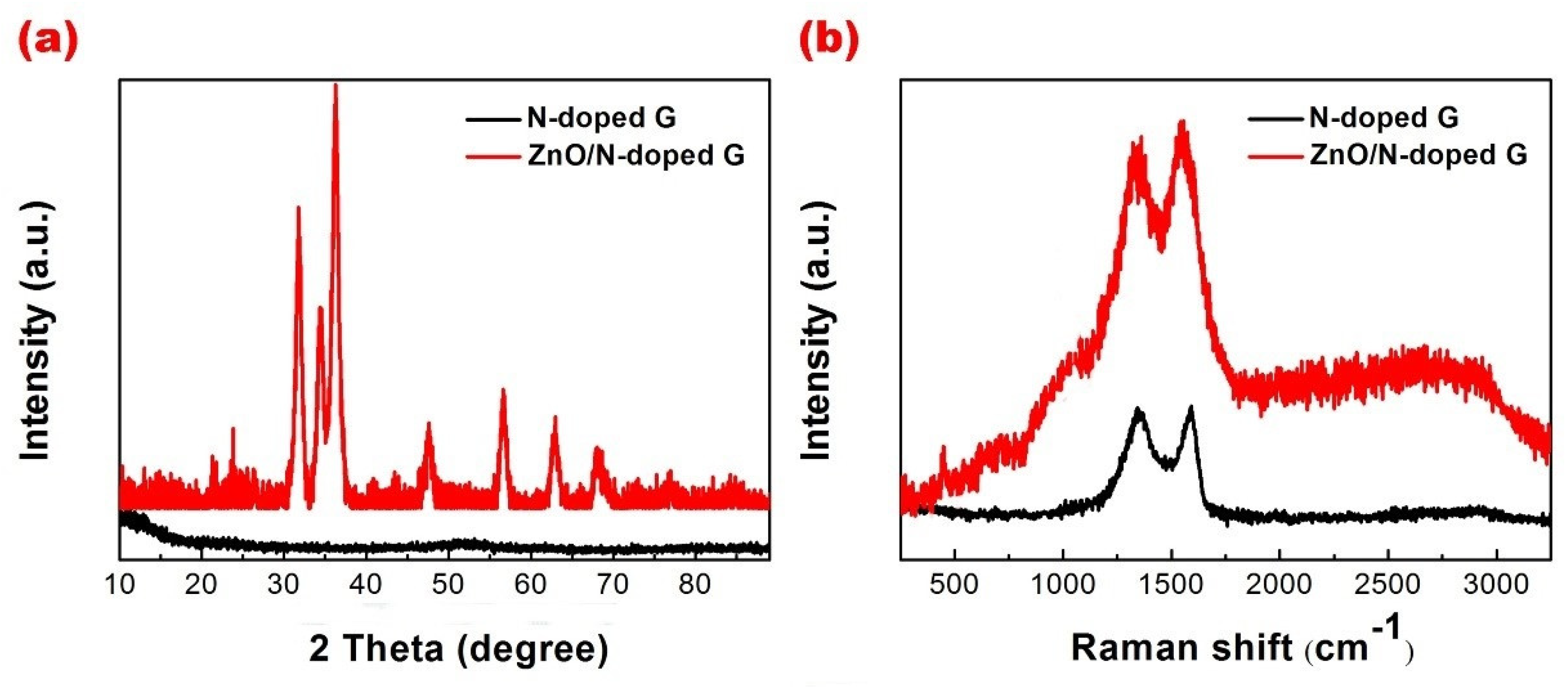
Figure 2a shows the XRD patterns of NDG and the ZnO/NDG composite. Broad diffraction peaks observed at 26.3° and 43.3° can be respectively ascribed to (022) and (100) crystal lattice planes of NDG. Peaks at 31.8°, 34.4°, 36.2°, 47.5°, 56.6°, 62.9°, 68.0°, and 69.1° correspond respectively to (100), (002), (101), (102), (110), (103), (112), and (201) crystal lattice planes of hexagonal structure of ZnO (JCPDS 36-1451). It is to be noted that these peaks are relatively broad in the XRD pattern of the ZnO/NDG composite, which suggests that the ZnO particles are nanosized. The Raman spectra of NDG and the ZnO/NDG composite are shown in Figure 2b. The peak observed at 475 cm−1 in the spectra of the ZnO/NDG composite corresponds to crystalline ZnO, which is in accordance with the XRD results. The calculated intensity ratio of the D and the G bands (ID/IG) gives an indication of the defect state of graphene sheets. The values of ID/IG were calculated to be 1.054 and 1.010 for the ZnO/NDG composite and NDG, respectively; these values suggest that ZnO nanoparticles were introduced onto the surface of the NDG nanosheets without inducing significant defects.
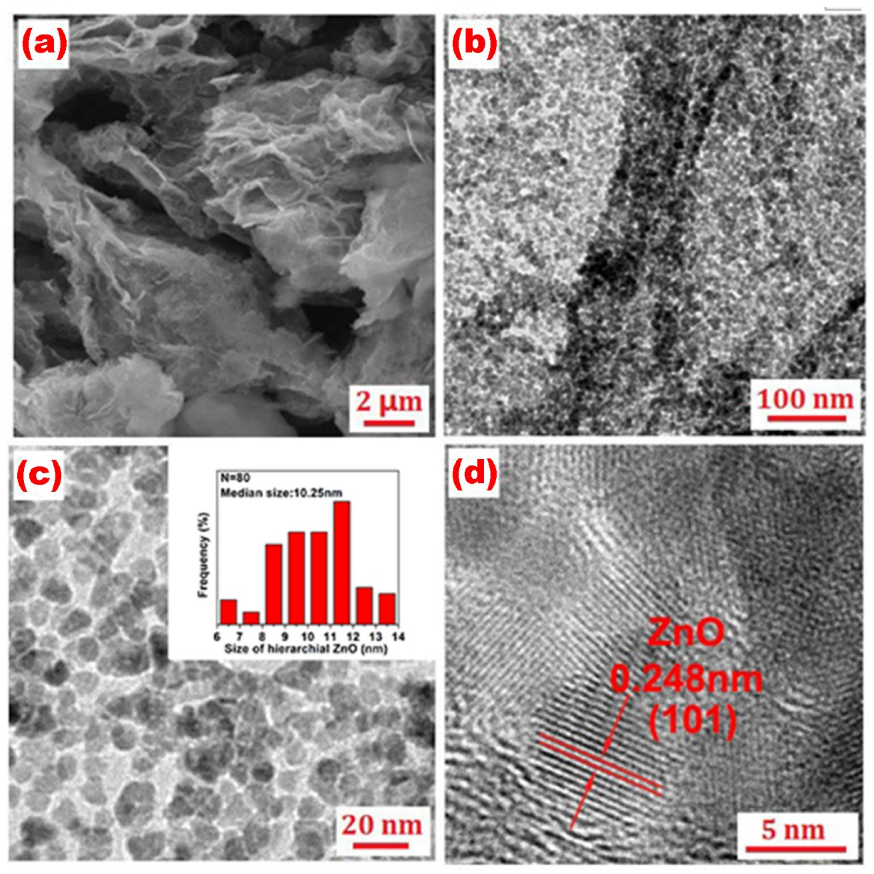
The SEM and the TEM images of the ZnO/NDG composite are shown in Figure 3. As seen in Figure 3a, porous NDG nanosheets are coated with nanosized ZnO particles. The TEM images (Figure 3b–d) further confirm that the ZnO nanoparticles in the as-prepared ZnO/NDG composite are uniformly dispersed on the NDG sheets; the sizes of the ZnO particles range from 5 to 14 nm, as shown in Figure 3c. The inset in Figure 3c shows the particle diameter distribution of ZnO obtained from the TEM data; the ZnO particles have a uniform size distribution with an average diameter of 10 ± 2 nm. The lattice fringes of ZnO with an interlayer distance of 0.248 nm corresponding to the (101) plane are evident in the high resolution TEM image (Figure 3d).
Figure 4a shows the top-view SEM image of a conventional separator revealing the presence of abundant pores, several micrometers in size. These make it difficult for the separator to block the shuttling of LiPs (1–1.8 nm). Figure 4b shows the typical front-view SEM image of the ZnO/NDG composite-coated separator. The rough surface of the modified separator forms a perfect blanket covering the pores of the conventional separator; this also provides a larger contact area with the electrolyte and contributes to suppression of charge transfer resistance. The cross-sectional view of the modified separator shown in the inset of Figure 4b displays a uniform coating layer with a thickness of approximately 25 μm.
Figure 5a,b depict the charge/discharge profiles of the cell with and without the ZnO/NDG composite-coated separator at a rate of 0.1 C, respectively; two-step redox reaction features are revealed. The plateaus at 2.4 and 2.1 V are indexed to the oxidation of S8 to LiPs and the reduction of LiPs to sulfides [5], respectively. The enhanced electrochemical performance of the ZnO/NDG composite-coated separator is evident from the overlapping upper discharge plateaus even after 200 cycles as well as the much higher capacity. This confirms that the cell with ZnO/NDG composite-coated separator is superior in terms of polysulfide inhibition and electrochemical stability. As seen in Figure 5c,d, the performance of the cell with the ZnO/NDG composite-modified separator is remarkably higher than that of the cell with the conventional separator. Figure 5c presents the rate performance of the cell with and without the modified separator. The average discharge capacities of the cell with the modified separator were 913, 785, 657, and 563 mAh·g−1 at discharge/charge rates of 0.1, 0.5, 1, and 2 C, respectively; these capacities are much higher than those of the cell with the conventional separator. It is worth noting that, the cell recovered its capacity of 842 mAh·g−1 when the discharge/charge rate was returned to the initial value, thus confirming a steady cycling performance. Upon conducting the cycling test at 0.1 C (Figure 5d), the cell with the ZnO/NDG composite-coated separator delivered a discharge capacity of 942 mAh·g−1 for the first cycle and retained approximately 90.02% of its initial discharge capacity after the 200th cycling process. However, the cell with the conventional separator exhibited a reduced capacity and rapidly lost 26.72% of its initial capacity after the 200th cycling test. In addition, we found that the cell with ZnO/NDG composite-coated separator exhibited a higher Coulombic efficiency (100% ± 2%) than the cell with conventional separator (97% ± 2%) halfway through the test. These results suggest that the as-prepared ZnO/NDG composite can efficiently suppress the shuttling of LiPs during charge/discharge cycling. This is attributed to the synergistic effect of nanosized ZnO particles and NDG; the former can chemically absorb S-related species, and the latter can act as an “upper current” collector to reuse the LiPs captured by the functional interlayer. The unique 2D structure of ZnO nanoparticles anchored on the NDG network enables a faster ion transport in the compact NDG, and the additional electron pathways to the active material improves the redox chemistry of S and enhances active material utilization.
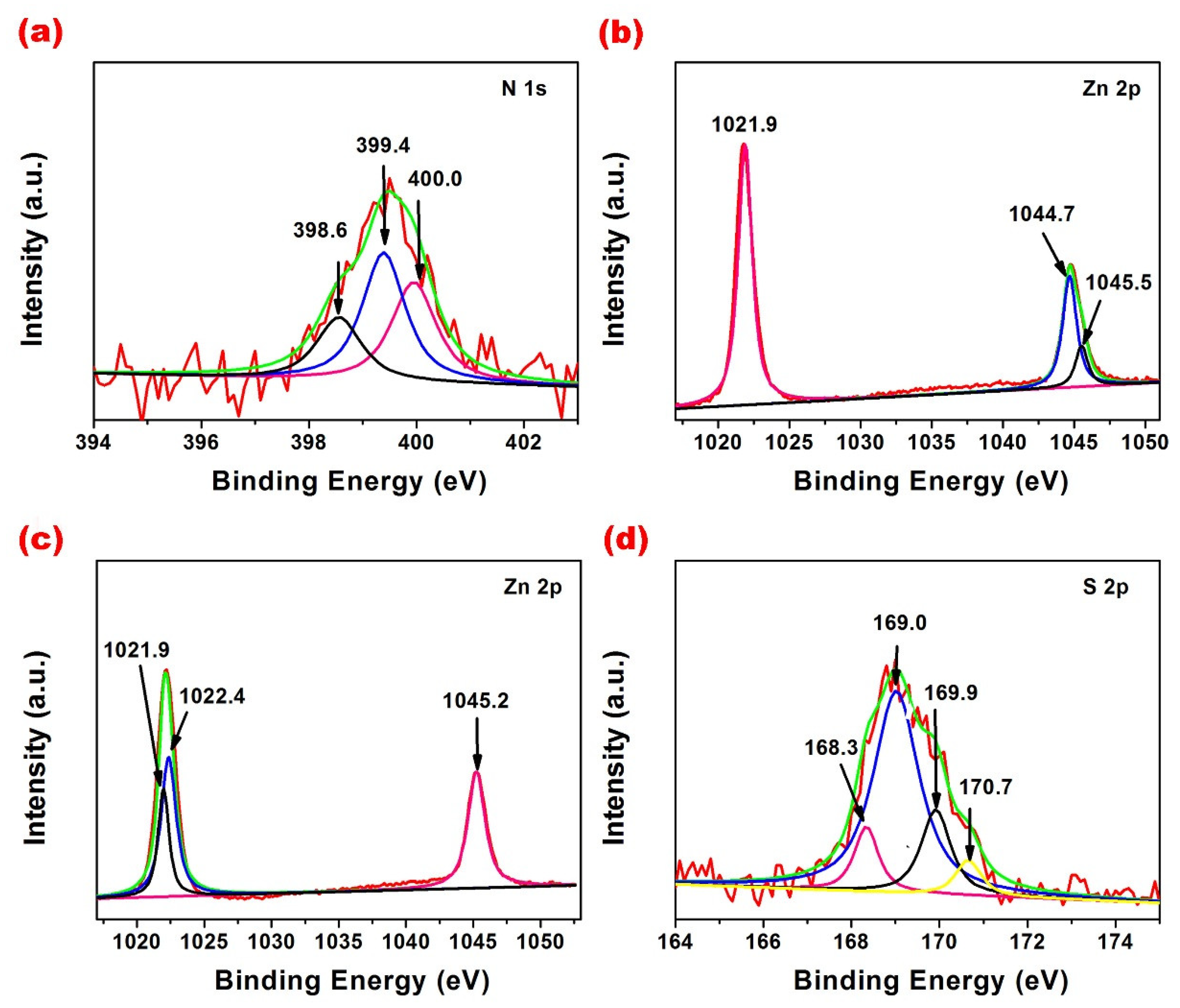
XPS studies were carried out to investigate the chemical composition of the ZnO/NDG composite. Figure 6a shows the high-resolution N 1s spectrum. The peaks centered at 398.1 and 398.5 eV are assigned to pyridinic-type N (a N atom that replaces a C atom in a hexagon) [28]. The peak at 399.2 eV is associated with ionized pyridine N [28]. The peaks at 399.9 and 400.6 eV correspond to pyrrolic N (a nitrogen atom in a five-membered ring), and the peak at 401.1 eV is attributed to graphitic N. In the Zn 2p spectrum (Figure 6b), the peak centered at 1021.9 eV is assigned to ZnO 2p 3/2, and peaks at 1044.7 and 1045.5 eV are indexed to ZnO 2p 1/2 (according to the NIST database). The above results indicate that the two dimensional ZnO/NDG composite was successfully fabricated using the simple in situ sol-gel technique. Interestingly, comparing Figure 6b,c, it is evident that the peak at 1021.9 eV (ZnO 2p 3/2) before charge/discharge cycling is split into two peaks centered at 1021.9 (ZnO 2p 3/2 or ZnSO4 2p 3/2; NIST database) and 1022.4 eV (ZnS 2p 3/2; NIST database) after cycling; this confirms the strong chemical interaction between ZnO and LiPs. The peak located at 1045.2 eV in Figure 6c is assigned to ZnO 2p 1/2. In the S 2p spectrum obtained after charge/discharge cycling (Figure 6d), the peak centered at 168.3 eV is assigned to sulfate, and the peaks at 169.0, 169.9, and 170.7 eV are related to metal-SO42− species, which is in good accordance with the analysis results of Zn 2p spectrum after cycling.
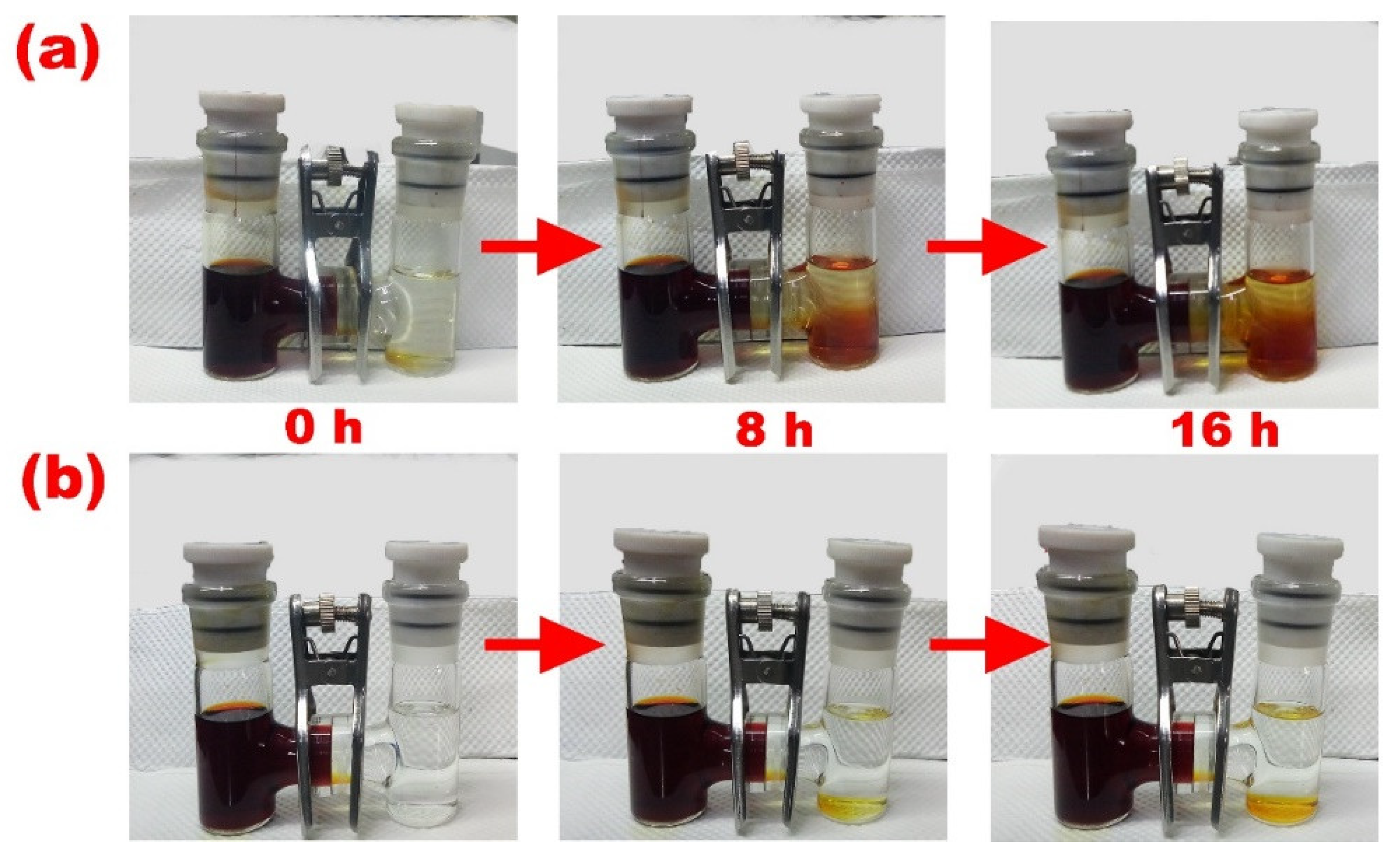
To elucidate the contribution of the ZnO/NDG composite modified separator in alleviating the “shuttle effect”, experiments using H-type glass cells were carried out. As shown in Figure 7, the deep brown solution on the left side is a mixture of DOL/DME with 0.06 M Li2S6 as an additive. The solution on the right side contains pure DOL/DME. Driven by the concentration gradient, Li2S6 would inevitably diffuse through the membrane from the left side to the right side, resulting in a change in color. In the cells assembled with the conventional separator (Figure 7a), the color of the cell on the right changed evidently over time, confirming that the conventional separator was unable to impede the shuttle of sulfur related species. In comparison, in the cells with the ZnO/NDG composite coated separator (Figure 7b), there was no distinct color change in the cell on the right even after 16 h, suggesting that the shuttling of polysulfide was efficiently suppressed by the ZnO/NDG composite coated separator.

4. Conclusions

In summary, ZnO/NDG composite was prepared via a facile in situ sol-gel technique. The chemical interaction between ZnO nanoparticles and polysulfides was confirmed by comparing the XPS results before and after the charge/discharge cycling process. The performance of the Li/S battery was significantly enhanced by the synergistic effect of ZnO nanoparticles and NDG. Specifically, the cell with the ZnO/NDG composite-coated separator delivered a high initial capacity of 942 mAh·g−1 at 0.1 C and retained approximately 90.02% of its initial discharge capacity after the 200th cycling process. The discharge/charge rate performance of the cell with the ZnO/NDG composite-coated separator was also significantly higher than that of the cell with the conventional separator.

Author Contributions

Data curation, F.G.; Investigation, R.M. and A.D.; Methodology, T.T. and M.W.; Project administration, M.D. and X.Z.; Resources, Y.F.; Writing: original draft, S.W.; Writing: review and editing, S.W.

Acknowledgments

The author thanks the financial of The National Natural Science Foundation of China (grant numbers 51501055, 51601056); the Natural Science Foundation of Hebei Province of China (grant number E2017202012); and the Natural Science Foundation of Shandong Province (ZR2014BL004).

Conflicts of Interest

The authors declare no conflict of interest.

References

  1. Bruce, P.G.; Freunberger, S.A.; Hardwick, L.J.; Tarascon, J.M. Li-O2 and Li-S batteries with high energy storage. Nat. Mater. 2012, 11, 19–29. [Google Scholar] [CrossRef] [PubMed]
  2. Bruce, P.G.; Hardwick, L.J.; Abraham, K.M. Lithium-air and lithium-sulfur batteries. Mrs. Bull. 2011, 36, 506–512. [Google Scholar] [CrossRef]
  3. Zhang, Z.; Lai, Y.; Zhang, Z.; Li, J. A functional carbon layer-coated separator for high performance lithium sulfur batteries. Solid State Ionics 2015, 278, 166–171. [Google Scholar] [CrossRef]
  4. Jiang, Y.; Chen, F.; Gao, Y.; Wang, Y.; Wang, S.; Gao, Q.; Jiao, Z.; Zhao, B.; Chen, Z. Inhibiting the shuttle effect of Li-S battery with a graphene oxide coating separator: Performance improvement and mechanism study. J. Power Sources 2017, 342, 929–938. [Google Scholar] [CrossRef]
  5. Evers, S.; Yim, T.; Nazar, L.F. Understanding the nature of absorption/adsorption in nanoporous polysulfide sorbents for the Li-S battery. J. Phys. Chem. C 2012, 116, 19653–19658. [Google Scholar] [CrossRef]
  6. Ji, X.; Evers, S.; Black, R.; Nazar, L.F. Stabilizing lithium-sulphur cathodes using polysulphide reservoirs. Nat. Commun. 2011, 2, 325. [Google Scholar] [CrossRef] [PubMed]
  7. Pang, Q.; Kundu, D.; Cuisinier, M.; Nazar, L.F. Surface-enhanced redox chemistry of polysulphides on a metallic and polar host for lithium-sulphur batteries. Nat. Commun. 2014, 5, 4759. [Google Scholar] [CrossRef] [PubMed] [Green Version]
  8. Wu, H.; Huang, Y.; Zhang, W.; Sun, X.; Yang, Y.; Wang, L.; Zong, M. Lock of sulfur with carbon black and a three-dimensional graphene@carbon nanotubes coated separator for lithium-sulfur batteries. J. Alloy. Compd. 2017, 708, 743–750. [Google Scholar] [CrossRef]
  9. Chai, L.; Wang, J.; Wang, H.; Zhang, L.; Yu, W.; Mai, L. Porous carbonized graphene-embedded fungus film as an interlayer for superior Li-S batteries. Nano Energy 2015, 17, 224–232. [Google Scholar] [CrossRef]
  10. Han, P.; Manthiram, A. Boron- and nitrogen- doped reduced graphene oxide coated separators for high-performance Li-S batteries. J. Power Sources 2017, 369, 87–94. [Google Scholar] [CrossRef]
  11. Li, H.; Sun, L.; Zhang, Y.; Tan, T.; Wang, G.; Bakenov, Z. Enhanced cycle performance of Li/S battery with the reduced graphene oxide/activated carbon functional interlayer. J. Energy Chem. 2017, 26, 1276–1281. [Google Scholar] [CrossRef]
  12. Chung, S.H.; Manthiram, A. High-Performance Li-S batteries with an Ultra-lightweight MWCNT-Coated Separator. J. Phys. Chem. Lett. 2015, 5, 1978–1983. [Google Scholar] [CrossRef] [PubMed]
  13. Chen, G.; Song, X.; Wang, S.; Wang, Y.; Gao, T.; Ding, L.X.; Wang, H. A multifunctional separator modified with cobalt and nitrogen co-doped porous carbon nanofibers for Li-S batteries. J. Membr. Sci. 2018, 548, 247–253. [Google Scholar] [CrossRef]
  14. Zhu, J.; Ge, Y.; Kim, D.; Lu, Y.; Chen, C.; Jiang, M.; Zhang, X. A novel separator coated by carbon for achieving exceptional high performance lithium-sulfur batteries. Nano Energy 2016, 20, 176–184. [Google Scholar] [CrossRef]
  15. Balach, J.; Jaumann, T.; Mühlenhoff, S.; Eckert, J.; Giebeler, L. Enhanced polysulphide redox reaction using a RuO2 nanoparticle-decorated mesoporous carbon as functional separator coating for advanced lithium-sulphur batteries. Chem. Commun. 2016, 52, 8134–8137. [Google Scholar] [CrossRef] [PubMed]
  16. Song, H.; Zuo, C.; Xu, X.; Wan, Y.; Wang, L.; Zhou, D.; Chen, Z. A thin TiO2 NTs/GO hybrid membrane applied as an interlayer for lithium-sulfur batteries. RSC Adv. 2018, 8, 429–434. [Google Scholar] [CrossRef]
  17. Shao, H.; Wang, W.; Zhang, H.; Wang, A.; Chen, X.; Huang, Y. Nano-TiO2 decorated carbon coating on the separator to physically and chemically suppress the shuttle effect for lithium-sulfur battery. J. Power Sources 2018, 378, 537–545. [Google Scholar] [CrossRef]
  18. Wei, S.Z.; Li, W.; Cha, J.J.; Zheng, G.; Yang, Y.; Mcdowell, M.T.; Hsu, P.C.; Cui, Y. Sulphur-TiO2 yolk-shell nanoarchitecture with internal void space for long-cycle lithium-sulphur batteries. Nat. Commun. 2013, 4, 1331. [Google Scholar]
  19. Tang, Q.; Li, H.; Zhang, J.; Lin, Z.; Pan, Y.; Hu, Q.; You, Y.; Ye, Y. A dual-faced interlayer prepared by electron beam evaporation for enhanced-performance lithium-sulfur batteries. Rsc Adv. 2017, 7, 44035–44042. [Google Scholar] [CrossRef]
  20. Xu, Q.; Hu, G.C.; Bi, H.L.; Xiang, H.F. A trilayer carbon nanotube/Al2O3/polypropylene separator for lithium-sulfur batteries. Ionics 2014, 21, 981–986. [Google Scholar] [CrossRef]
  21. Liu, J.; Yuan, L.; Yuan, K.; Li, Z.; Hao, Z.; Xiang, J.; Huang, Y. SnO2 as high-efficiency polysulfide trap in lithium-sulfur battery. Nanoscale 2016, 8, 13638–13645. [Google Scholar] [CrossRef] [PubMed]
  22. Liu, M.; Li, Q.; Qin, X.; Liang, G.; Han, W.; Zhou, D.; He, Y.B.; Li, B.; Kang, F. Suppressing self-discharge and shuttle effect of lithium-sulfur batteries with V2O5-decorated carbon nanofiber interlayer. Small 2017, 13. [Google Scholar] [CrossRef] [PubMed]
  23. Kong, W.; Yan, L.; Luo, Y.; Wang, D.; Jiang, K.; Li, Q.; Fan, S.; Wang, J. Li-S batteries: Ultrathin MnO2/graphene oxide/carbon nanotube interlayer as efficient polysulfide-trapping shield for high-performance Li-S batteries. Adv. Funct. Mater. 2017, 27. [Google Scholar] [CrossRef]
  24. Ma, G.Q.; Wen, Z.Y.; Wang, Q.S.; Jin, J.; Wu, X.W.; Zhang, J.C. Effects of CeO2 Nano-crystal on electrochemical properties of Lithium/Sulfur batteries. J. Inorg. Mater. 2015, 30, 913–918. [Google Scholar]
  25. Kong, Y.; Luo, J.; Jin, C.; Yuan, H.; Sheng, O.; Zhang, L.; Fang, C.; Zhang, W.; Huang, H.; Xia, Y. Enhanced sulfide chemisorption by conductive Al-doped ZnO decorated carbon nanoflakes for advanced Li-S batteries. Nano Res. 2018, 11, 477–489. [Google Scholar] [CrossRef]
  26. Li, H.; Wei, Y.; Zhang, Y.; Zhang, C.; Wang, G.; Zhao, Y.; Yin, F.; Bakenov, Z. In situ sol-gel synthesis of ultrafine ZnO nanocrystals anchored on graphene as anode material for Lithium-ion batteries. Ceram. Int. 2016, 42, 12371–12377. [Google Scholar] [CrossRef]
  27. Yin, F.; Liu, X.; Zhang, Y.; Zhao, Y.; Menbayeva, A.; Bakenov, Z.; Wang, X. Well-dispersed sulfur anchored on interconnected polypyrrole nanofiber network as high performance cathode for lithium-sulfur batteries. Solid State Sci. 2017, 66, 44–49. [Google Scholar] [CrossRef] [Green Version]
  28. Holloway, B.C.; Kraft, O.; Shuh, D.K.; Kelly, M.A.; Nix, W.D. Interpretation of X-ray photoelectron spectra of elastic amorphous carbon nitride films. Appl. Phys. Lett. 1999, 74. [Google Scholar] [CrossRef]
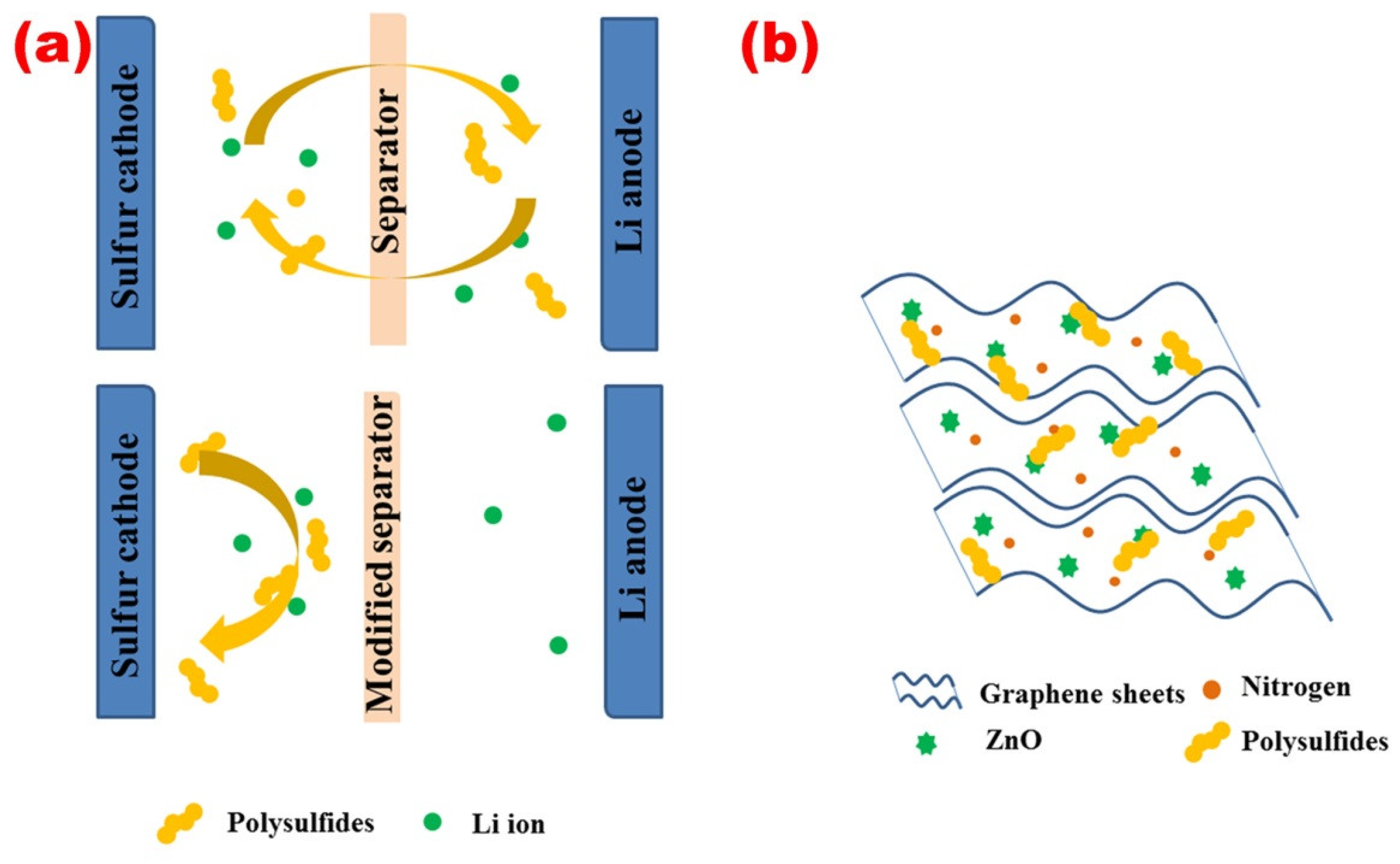
Figure 1. (a) Schematic diagram of the cell configuration with a conventional separator (top) and the ZnO/N-doped composite-coated separator (bottom). (b) Functional mechanism of the ZnO/N-doped composite-coated separator.
Metals 08 00755 g001
Figure 2. (a) XRD patterns of NDG and the ZnO/NDG composite. (b) Raman spectra of NDG and the ZnO/NDG composite.
Metals 08 00755 g002
Figure 3. (a) SEM image of the ZnO/NDG composite. (b) TEM image of the ZnO/NDG composite. (c) Low-magnification TEM image for ZnO/NDG composite. The inset shows the particle size distribution of ZnO. (d) HRTEM image of the ZnO/NDG composite.
Metals 08 00755 g003
Figure 4. Top-view SEM images of the (a) Conventional separator and the (b) ZnO/NDG composite-coated separator. The inset in (b) shows the cross-sectional view of the modified separator.
Metals 08 00755 g004
Figure 5. Charge/discharge voltage-capacity profiles of the cell (a) with and (b) without the ZnO/NDG composite-coated separator. (c) Rate performance of the cell with and without the ZnO/NDG composite-coated separator. (d) Cycling performance and Coulombic efficiency of the cell with the ZnO/NDG composite-coated separator.
Metals 08 00755 g005
Figure 6. X-ray photoelectron spectra of (a) N 1s and (b) Zn 2p before charge/discharge cycling. X-ray photoelectron spectra of (c) Zn 2p and (d) S 2p after charge/discharge cycling.
Metals 08 00755 g006
Figure 7. Photographs of H-type glass cells assembled with the (a) conventional separator and the (b) ZnO/NDG composite-coated separator.
Metals 08 00755 g007