Interfacial Microstructure and Shear Strength of Brazed Cu-Cr-Zr Alloy Cylinder and Cylindrical Hole by Au Based Solder

State Key Laboratory of High Performance Complex Manufacturing, Central South University, Changsha 410083, China
*
Author to whom correspondence should be addressed.
Metals 2017, 7(7), 247; https://doi.org/10.3390/met7070247
Submission received: 6 May 2017
/
Revised: 26 June 2017
/
Accepted: 27 June 2017
/
Published: 3 July 2017
Abstract
:Au-Ge-Ni solder was chosen for brazing of the Cu-Cr-Zr alloy cylinder and a part with a cylindrical hole (sleeve) below 550 °C. The Au based solder was first sintered on the surface of the cylinder and then brazed to the inner surface of the sleeve. The effects of the heating process, the temperature and the holding time at the temperature on the microstructure of the sintered layer on the surface of the cylinder, the brazed interfacial microstructure, and the brazed shear strength between the cylinder and the sleeve were investigated by scanning electron microscope, energy dispersive X-ray spectroscopy analysis, and tensile shear tests. By approach of side solder melt feeding and brazing under proper parameters, the voids and micro cracks due to a lack of enough solder melt feeding are greatly lessened and the brazed shear strength of 100 MPa is ensured even with large clearances around 0.01 mm.
1. Introduction
Cu and Cu based alloys have found wide and important applications in many fields, especially in electrical appliances and electronic products [1,2]. In an electronic product, a long cylinder is welded to the inner surface of a sleeve. Both of them are made of red copper with the tensile strength of 280 MPa. With upgrading and updating of the product, the strength of the cylinder and the sleeve are designed to be above 400 MPa after welding. By taking into account strength and the electrical conductivity, Cu-Cr-Zr alloy (chemical composition: 0.94 wt % Cr, 0.137 wt % Zr, and Cu in balance) was chosen. The tensile strength of this alloy is above 500 MPa. However, its strength will decline to below 400 MPa when the temperature is over 550 °C [2,3]. This means that the cylinder and the sleeve must be welded below this temperature.
It is known that several welding methods are widely used for fabrication of copper and its alloys, such as laser welding, ion beam welding, tungsten arc inert gas welding, metal arc inert gas welding, and brazing [4,5]. Kaya et al. [6] have developed a new procedure by adding an external electrical current to the conventional diffusion welding for austenitic stainless steel and copper materials. In recent years, welding of copper materials and dissimilar material joints by the friction stirring process is a hot topic. Bisadi et al. [7] have reported the effect of tool rotation speed on mechanical properties and formation of intermetallic compounds of copper-Al5083 friction stir welded butt joints. Qiao et al. [8] and Shanjeevi et al. [9] have reported their study on optimization of friction welding parameters for AISI 304L austenitic stainless steel and copper joints in power generators. Elyasi et al. [10] have reported their study on the effect of tool tilt angle on properties and formation of intermetallic compounds in friction stir welded A441 AISI to AA1100 aluminum butt joints.
By taking into consideration of the strength of the weld and the decline of the Cu-Cr-Zr alloy strength during the welding process, the approach by solder brazing below 550 °C was chosen.
As for low melting temperature soldering, Sn-Pb eutectic solder alloy has been widely used for decades due to its excellent performances [11,12,13]. However, legislation, like Institute of Electrical and Electronics Engineers (IEEE) and Restriction of Hazardous Substances (RoHS), has restricted the application of this kind of solder mainly due to the toxicity of Pb. Therefore, various Pb-free alloys, such as Sn-Ag-Cu and Sn-Zn-Bi solder alloys, have been developed to replace the conventional eutectic Sn-Pb solder alloys. It has been reported that the addition of small amounts of Ni, Cu, and/or Sb to the solder alloys can refine the microstructure and improve the mechanical properties [11,12,13]. As for Sn-8Zn-3Bi-1.5Sb solder alloy, the tensile strength of the brazed joint can reach about 85 MPa [11]. However, the mechanical strength cannot meet the requirement for brazing of the Cu-Cr-Zr alloy. The Ag-based solder alloys, such as Ag-Cu, Ag-Sn, Ag-Al, Ag-Zn, and Ag-Ga, can be applied to reach a shear strength of more than 150 MPa [14]. However, the melting temperature of this series of solder alloys is higher than 500 °C.
As for brazing of copper and its alloys, Au based solders are widely used due to their excellent electrical conductivity, good electromigration resistance, and high fatigue resistance [15,16,17,18,19]. These mainly include Au-Sn, Au-Ge, Au-In, and Au-Ni. As for Au-Sn solder, although the eutectic point of Au-Sn is 282 °C, the brazed tensile strength is only about 48 MPa [15,16]. While for Au-Ni and Au-Cu solders, they are not suitable to be used for Cu-Cr-Zr alloy as their eutectic points are above 900 °C [13]. Recently Au-12Ge (wt %) eutectic alloy has attracted great attention as are no Au-Ge intermetallic phases in its cast structure and its eutectic point is 365 °C [18,19,20,21,22]. It has been used for brazing of Cu, Ni, and other substrates.
In this work, with the aim of brazing the Cu-Cr-Zr cylinder and sleeve below 550 °C, while ensuring the shear strength of the brazed joints is above 90 MPa, properties of the newly developed Au-Ge solder with an addition of minor Ni and Cu were tested; the effect of the wrapping of the solder foil and the sintering process on the microstructure of the sintered layer on the surface of the cylinder were investigated by scanning electron microscope (SEM) and Energy dispersive X-ray spectroscopy (EDS), and the effect of the brazing process and the side solder melt feeding on the interfacial microstructure, including micro defects and the brazed shear strength, were studied by SEM and tensile shear tests.
2. Materials and Methods
The cylinders and the sleeves were made by a Cu-Cr-Zr alloy with the chemical composition of: 0.94 wt % Cr, 0.137 wt % Zr, and Cu in balance.
The solder was the newly developed Au-Ge alloy with the chemical composition of: 10 wt % Ge, 1.5 wt % Ni, 0.5 wt % Cu, and Au in balance. The solder was fabricated by first melting and casting, then isothermal rolling, and finally finish rolling to 0.5 mm thick sheets and 0.08 mm thick foils.
The sintering of the solder onto the surface of the cylinder includes: first wrapping up of the solder foil on the surface of the cylinder, second, wrapping up of the solder foil by 0.08 mm thick 1Cr18Ni9Ti stainless steel foil, third, wrapping of the steel foil by steel wire or wrapping up of the steel foil by half sets and wrapping of the half sets by steel wire, and, finally, sintering in a vacuum aluminum brazing furnace at different temperatures and heating processes. The wrapping of the solder foil onto surface of the cylinder is shown in a schematic in Figure 1. Before the brazing to the sleeve, the surface solder layer sintered on the cylinders was precision cut.
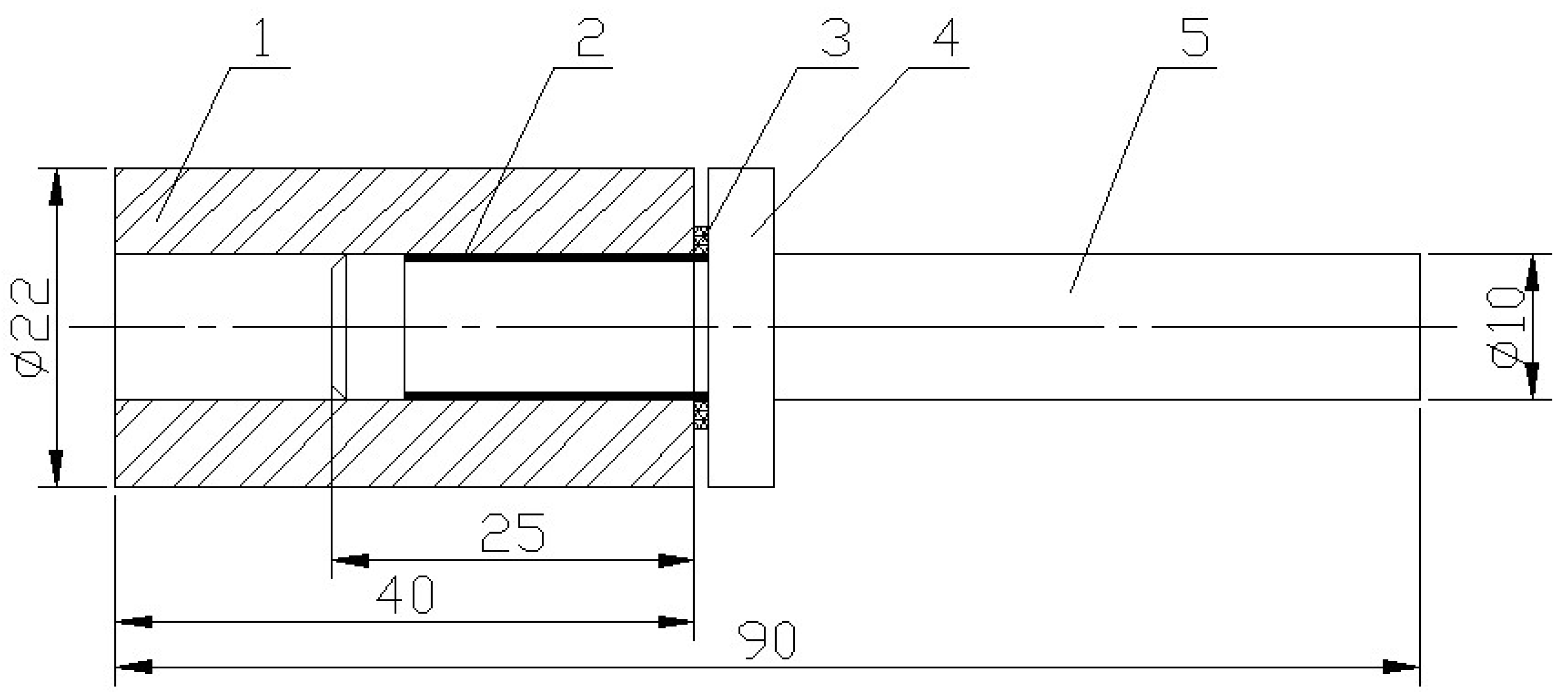
The brazing of the cylinder and the sleeve includes: first, surface precision cutting of the sintered cylinder, then, inserting it into the sleeve, finally, brazing in a vacuum aluminum brazing furnace under different temperatures and heating processes. The shape and the size of the cylinder and the sleeve are shown in Figure 2. It should be noted that a piece of solder sheet with a thickness of 0.5 mm is set at one side of the brazing seam. In the results in Section 3.3.1, it can be seen that the brazed shear strength is below 90 MPa and there are many voids and micro cracks related to lack of solder melt feeding during solidification of the solder melt in the brazing seam. The role of this solder piece at the seam side is to lessen the brazing defects by providing enough solder melt feeding during solder melt solidification, and, therefore, to promote brazed shear strength.
The tensile shear tests were carried out on a 10-tonne test machine. The test continued until the specimens failed with a cross-head speed of 1 mm/min. The shear strength is the maximum load divided by the area of the brazed cylinder (i.e., π × cylinder diameter 8.3 mm × brazed length of the cylinder 10 mm). Figure 3 shows a description of the setup for the tensile shear test.
The cross-section morphologies of the sintered and brazed samples were characterized by SEM (Quanta-200, FEI Corporation, Hillsboro, OR, USA) with an accelerating voltage of 20 kV. Energy dispersive X-ray spectroscopy (EDS, Genesis 60 s, INCAPentaFET-x3, Oxford Instruments, Oxfordshire, UK) analysis was used to reveal the chemical composition of selected points/regions. The specimens for SEM examination and EDS analysis were mechanically polished with abrasive paper without etching. Siemens X-ray diffractometer D5000 (XRD, Cu Kα radiation, Rigaku, Tokyo, Japan) was used to identify the phase constitution of the solder and the solder sintered on the surface of the Cu-Cr-Zr alloy. The X-ray generator settings were 36 kV and 30 mA with a scan speed of 4°/min and a scan range from 10° to 95° (in 2θ). DTA (Differential Thermal Analysis) of the solder foil was carried out by the STA449C (Netzsch Instruments, Bavaria, Germany) apparatus at a heating rate of 15 K/min.
3. Results and Discussion
3.1. Properties of the Au Based Solder
Due to the obvious decrease in strength of the Cu-Cr-Zr alloy at above 550 °C, the brazing temperature for the Cu-Cr-Zr alloy cylinder and sleeve should be below this temperature. Therefore, by reference to a number of binary diagrams and the research results of [18,19,20,21,22], a new Au-Ge solder was developed by addition of 1.5 wt % Ni and 0.5 wt % Cu into Au-10 wt % Ge. The role of Ni and Cu is mainly to promote the strength of the solder and its wettability to the Cu-Cr-Zr alloy.
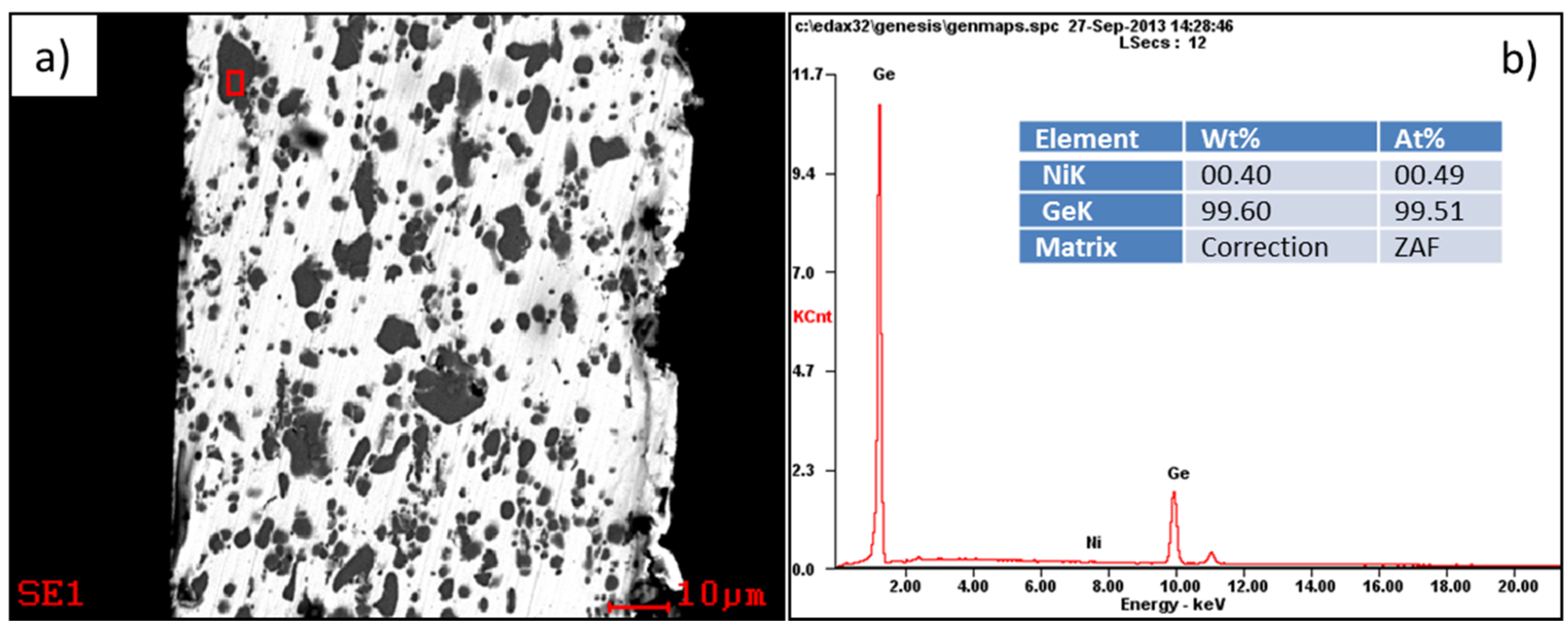
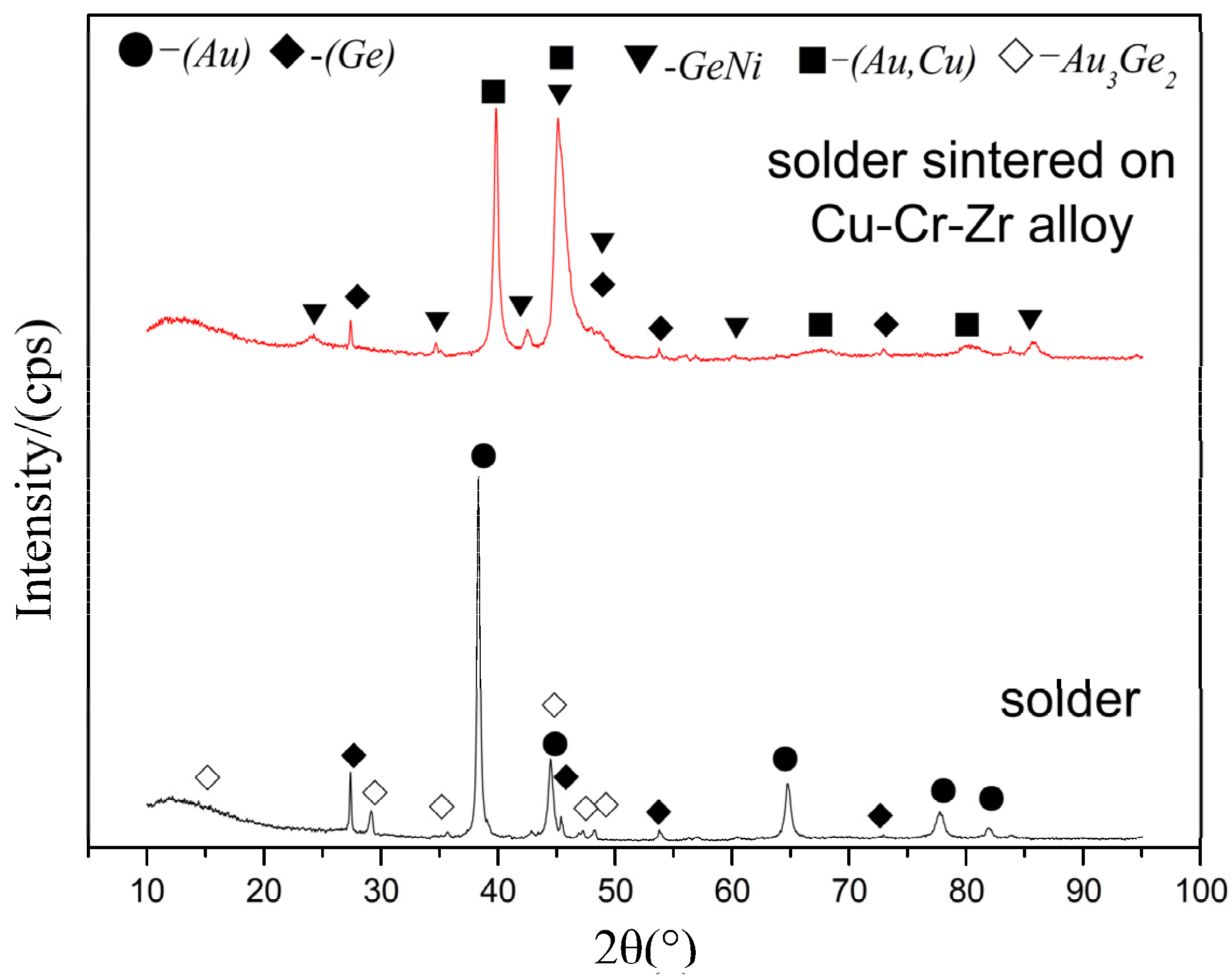
Figure 4 shows the cross-sectional SEM morphology of the solder foil. It can be seen that there are a number of polygonal particles with the size about 5–10 μm and a large number of small particles with the size about 2 μm distributed in the Au matrix. From the XRD pattern of the solder in Figure 5, it can be concluded that these particles are Ge particles and Au3Ge2 intermetallic particles. The EDS result in Figure 3b indicates that the large polygonal particles are Ge particles.
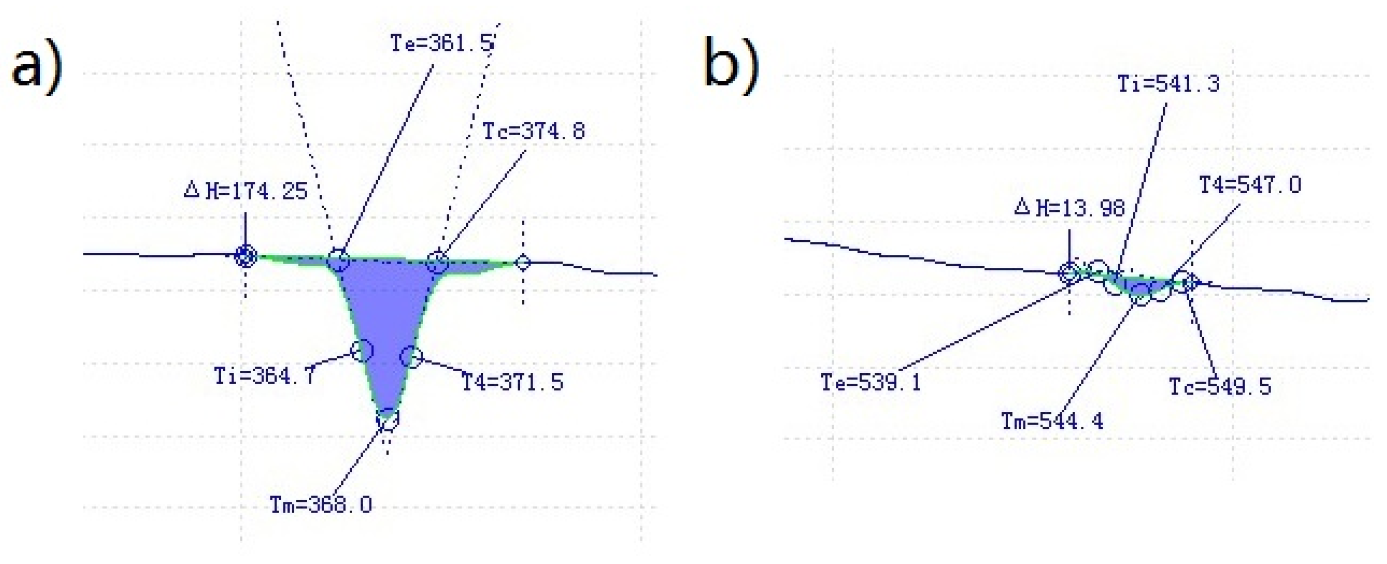
Figure 6 displays two inflection points of the DTA curve. It can be seen that the first and the second points are measured to be 368 and 544.4 °C, respectively. Therefore, the melting point of the solder can be determined to be 368 °C. The point at 544.4 °C is related to the melting of Ge-Ni intermetallic particles in the solder.
3.2. Sintering of the Solder to the Surface of the Cu-Cr-Zr Cylinder and the Microstructure
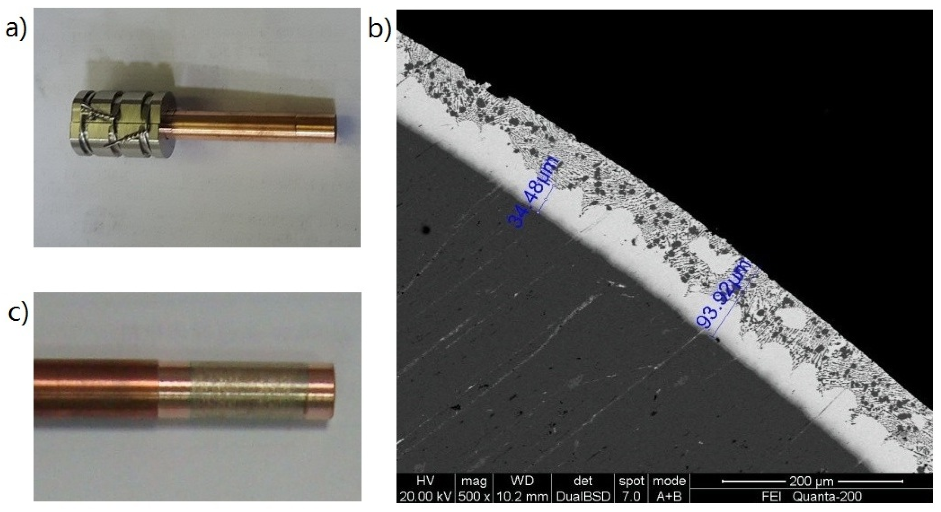
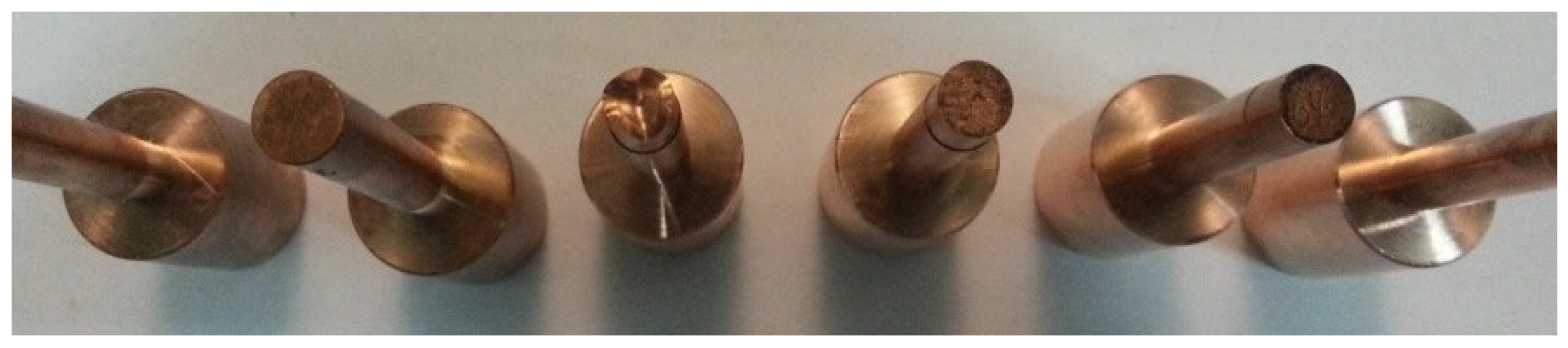
Figure 7 shows images of the Cu-Cr-Zr cylinder vacuum-sintered by the solder wrapped by steel wire. From Figure 7b it can be seen that the solder has covered the surface of the cylinder. However, bossing can be found on the surface of the sintered layer. Figure 7c shows the cross-sectional SEM image of the cylinder sintered by the solder. Although the elements of the solder have been diffused into the surface layer of the cylinder during the sintering process, there are long holes between the cylinder and the sintered layer. These are mainly due to the wrapping of the steel wire to the solder foil. During the surface precision cutting of the sintered layer, the sintered solder was removed totally at the holes, as shown in Figure 7d, which resulted in space gaps without solder between the cylinder and the sleeve and was, therefore, detrimental to obtaining brazing strength between the cylinder and the sleeve.
Figure 8 shows images of the Cu-Cr-Zr cylinder vacuum-sintered by the solder wrapped by half sets and steel wire. It was first heated to the temperature of 320 °C at a rate of 180 °C/h while holding at the temperature for 20 min, and then heated to the temperature of 420 °C at a rate of 200 °C/h and holding at the temperature for 15 min. From the cross-sectional SEM image of the sintered cylinder as shown in Figure 8b, it can be seen that the surface of the sintered solder on the cylinder is smooth and there is no bossing as was seen in Figure 7b,c. After surface precision cutting of the sintered layer, the sintered solder is relatively uniform on the surface of the cylinder, as shown in Figure 8c.
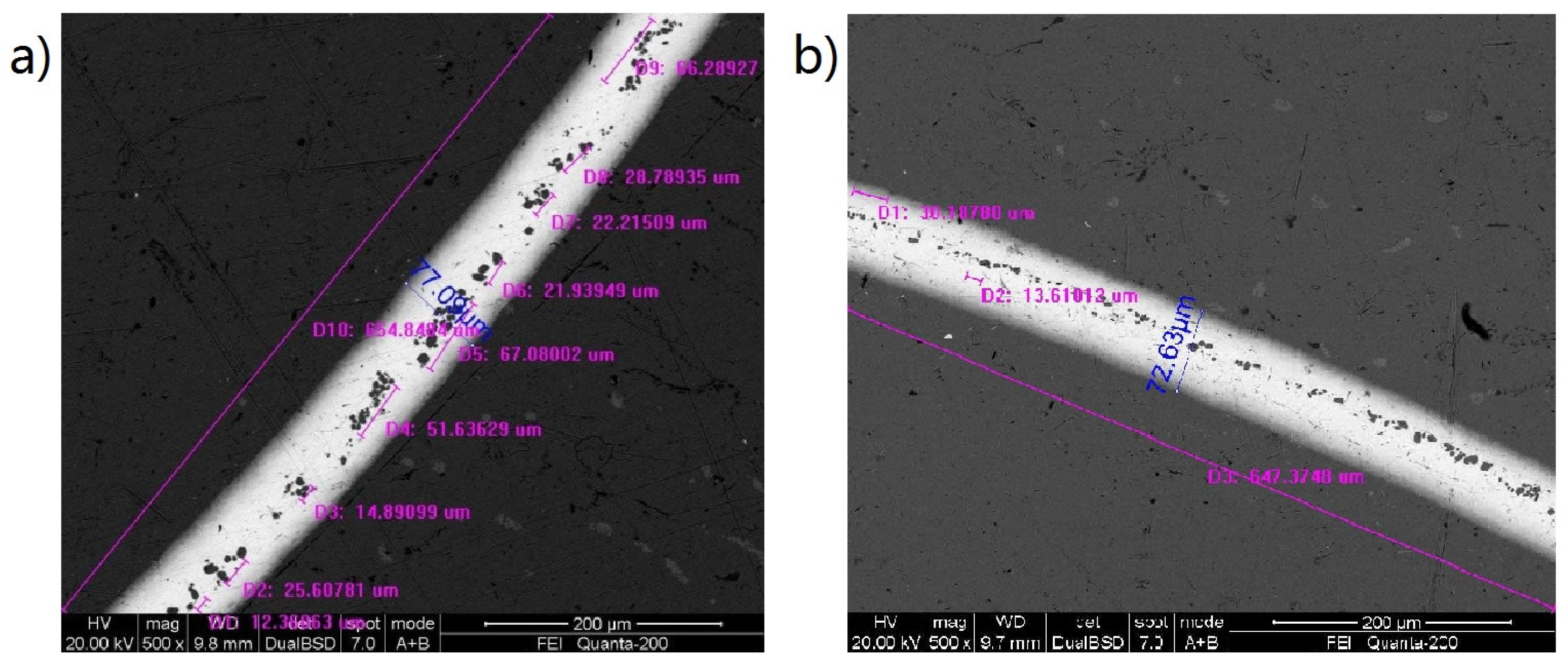
Figure 9 shows the cross-sectional SEM morphology of the sintered cylinder by magnification and the EDS spectrum. It can be seen that there are large amounts of polygonal particles and strip particles. From the XRD pattern of the solder sintered on the surface of Cu-Cr-Zr alloy in Figure 5, it can be concluded that these particles are Ge particles and Ge-Ni intermetallic particles. The EDS results demonstrate that the polygonal particles are Ge-Ni intermetallic compounds, with about 56 wt % Ge and 43 wt % Ni, and that the strip particles are Ge particles. During the sintered process, the elements of Au and Ge diffuse into the surface layer of the Cu-Cr-Zr cylinder with a thickness of about 20 μm.
During the sintering process, the heating rate, temperature, and holding time at the temperature can affect the melting of the solder foil, the thickness of the solder elements diffused into surface layer of the Cu-Cr-Zr cylinder, and the formation of intermetallic particles. In this work, the temperature was first heated to 320 °C at the rate of 180 °C/h and holding at the temperature for 20 min to homogenize the temperature of the samples. Then, the temperature was heated to the values for the sintering process. The temperatures for the sintering were 395, 420, and 430 °C. The heating rates to the final temperatures were 100 and 200 °C/h. The holding time at the sintering temperatures were 15 and 20 min. Figure 10 shows cross-sectional SEM morphologies of the sintered cylinder at temperatures of 395 and 430 °C. It can be found that the distributions of the intermetallic particles in Figure 10 are obviously different to that in Figure 8b. At 395 °C, the polygonal particles of the Ge-Ni intermetallic compounds are distributed at the outer side, as shown in Figure 10a, and at 430 °C, these particles are distributed at the inner side, as shown in Figure 10b. However, for the case sintered at 420 °C, these particles are almost uniform in their distribution in the sintered layer, as shown in Figure 8b. This can be ascribed to the effect of the temperature on the diffusion ability of Ni. The distribution of Ge-Ni particles in Figure 8b is advantageous to the brazing strength. The proper sintered process parameters are determined to be: first, heating the temperature to 320 °C at the rate of 180 °C/h and holding at the temperature for 20 min, then, heating the temperature to 420 °C at the rate of 200 °C/h and holding at the temperature for 15 min.
3.3. The Brazed Microstructure and Shear Strength
3.3.1. Effect of the Brazing Temperature and the Holding Time
During the brazing process of the sintered cylinder and the sleeve, two stages for the heating were adopted. The first stage was the same for all of the samples, i.e., the temperature was heated to 320 °C at a rate of 180 °C/h and holding at the temperature for 20 min. As for the second stage, the temperature was heated to 510, 535, and 550 °C at the rate of 600 °C/h, and holding at the temperature for 10, 20, and 30 min, respectively. As for brazing of the cylinder and the sleeve, it is obvious that the clearance between the sintered cylinder and the sleeve will have an effect on the brazing strength. Therefore, for all of the samples, the clearances between the sintered cylinder and the sleeve must be precision controlled. In our experiment these clearances were measured to be 0.002–0.004 mm at one side.
Figure 11 shows part of the brazed samples. Table 1 shows the shear strength for the samples brazed at temperature of 500, 535, and 550 °C. It can be seen that the brazing temperature had obvious effects on the shear strength. The highest shear strength was obtained at 535 °C. These shear strength values are related to the interfacial microstructure and micro defects formed between the cylinder and the sleeve during the brazing process at different temperatures.
Figure 12 shows the cross-sectional SEM morphologies of the brazed interfacial region for the sample brazed at 550 °C. In Figure 12a, two kinds of micro defects can be observed. The first kind of micro defect is the long crack or void along the circular interface between the cylinder and the sleeve as shown in Figure 12b. The formation of this defect can be ascribed to lack of melt feeding during the solidification process of the solder melt. The diffusion of Au and Ge into the surface layer of the Cu-Cr-Zr alloy cylinder and sleeve at high temperature accelerates this process. Obviously, the regions where these micro defects are located are weak. The second kind of micro defect is a lack of solder melt action on the surface of the sleeve as shown in Figure 12c. It can be seen that there is almost no diffusion layer on the inner surface of the sleeve. This is mainly due to the fact that the sintered solder layer that remained on the surface of the cylinder after surface precision cutting was too thin to bring the solder melt into contact with the surface of the sleeve. Of course, the regions where these micro defects are located are also weak. The total length of two kinds of micro defects along the interface is measured to be about 40% of the circular length of the interface.
Figure 13 shows the cross-sectional SEM morphologies of the brazed interfacial region for the sample brazed at 535 °C. Although there are still cracks and voids along the interface of the cylinder and the sleeve, they are short and discontinuous as compared with those in Figure 12b. The length of these micro defects along the interface was measured to be about 15% of the circular length of the interface. These short cracks and voids are also induced by a lack of melt feeding during the solidification process of the solder melt.
Table 2 shows the shear strength for the samples brazed for different holding time at 535 °C. It can be seen that the holding time at the brazing temperature also has obvious effects on the shear strength. Long holding time at the brazing temperature induce a decline of the shear strength. The highest shear strength was obtained for 10 min holding at 535 °C.
Figure 14a,b shows the cross-sectional SEM morphologies of the micro defects for the sample brazed for 30 min holding at 535 °C. As compared with the sample brazed for 10 min holding at 535 °C, in addition to the cracks along the interface as shown in Figure 13, the micro defects related to congregation of large amounts of Ge-Ni particles along the interface can be observed in Figure 13b and Figure 14a for 30 min holding at 535 °C. According to the EDS result in Figure 14d, these dark particles are Ge-Ni particles with about 55.2 wt % Ge and 43.17 wt % Ni. It is known that uniform distribution of small Ge-Ni particles in the brazed interfacial region is advantageous to the brazing strength. However, when these particles are congregated in the narrow interface and almost grow into contact each other, the brazed Au based solder seam will be ruptured by these particles. Generally, micro cracks accompany these ruptured seams, as shown in Figure 14c, due to hindering to the melt feeding by the congregated primary Ge-Ni particles. Therefore, the brazed shear strength declines greatly with the holding time at 535 °C.
3.3.2. Effect of the Brazing with Side Solder Feeding
The results in Section 3.3.1 demonstrated that in order to promote the brazing strength between the cylinder and the sleeve, it is necessary to reduce the extent of micro defects. One of the approaches is to ensure effective feeding of the solder melt during solidification. Hence, a disk of solder sheet with 0.5 mm thickness, as shown in Figure 2, was set up.
Figure 15 shows the brazed samples brazed at 535 °C and 10 min holding at the temperature with side solder feeding. Table 3 gives the shear strength of these samples. It can be seen that the average shear strength increased to 102.95 MPa from the highest value of 87.05 MPa in the above section. Furthermore, the dispersion of the shear strength is also reduced greatly by the approach of side solder feeding.
Figure 16 displays the cross-sectional SEM morphologies of the brazed interfacial microstructure for the sample brazed at 535 °C and 10 min holding at the temperature with side solder feeding. It can be seen that, firstly, there are almost no large cracks and voids along the interface between the cylinder and the sleeve and, secondly, the primary Ge-Ni particles are separately distributed in the brazed seam. By careful SEM examination along the total brazed interface, it was found that the length of the micro defects was below 4% of the circular length along the interface. The high brazed shear strength and its low dispersion can be ascribed to a significant reduction of the micro defects by the approach of side solder feeding.
In the above experiment, the clearances between the sintered cylinder and the sleeve were controlled to be 0.002–0.004 mm at one side. The precision control by cutting to the cylinder and the sleeve and the measurement of the clearance between them is requires a lot of time and manual effort. Therefore, it would be interesting to know if the brazing using side solder feeding is suitable to the large clearance values. Table 4 shows the measured clearances between the cylinder and the sleeve for 12 samples. They are between 0.011 and 0.015 mm at one side, obviously much bigger than 0.002–0.004 mm. Table 4 also shows the shear strength of these 12 samples. It can be seen that the maximum, the minimum, and the average shear strength are 105.3, 98.8, and 102.83 MPa, respectively. The dispersion of the shear strength is 6.32%. The results demonstrate that the brazing using side solder feeding is suitable to the case of large clearance values, i.e., 0.011–0.015 mm at one side, between the cylinder and the sleeve.
The brazing of a cylinder and a sleeve is a special structure which is not widely used. Although shear strength of more than 100 MPa is achieved, there are still micro defects in the brazed joint. The length of the micro defects is about 4% of the circular length of the brazed cylinder. Future research should look to reduce the micro defects to improve the mechanical strength. In addition, the reliability of the brazed joint under complex environments should be examined. As was studied in [21], the compatibility regarding electrical properties of the welding joint to the parent metals is important. In our experiments, compatibility of electrical resistance of the welding joint to the parent metal was achieved, which will be reported in a following paper.
4. Conclusions
- (1)
- The proper process parameters for sintering of a Au-Ge solder on the surface of the Cu-Cr-Zr cylinder by half sets are, first, heating the temperature to 320 °C at the rate of 180 °C/h and holding at the temperature for 20 min, then, heating the temperature to 420 °C at the rate of 200 °C/h and holding at the temperature for 15 min.
- (2)
- For brazing without side solder melt feeding, the highest brazed shear strength was 87.05 MPa. There were a number of voids and micro cracks along the interface of the cylinder and the sleeve due to lack of enough melt feeding and the congregation of large amounts of Ge-Ni particles with about 55.2 wt % Ge and 43.17 wt % Ni during solidification of the solder melt. High brazing temperature and long holding time at the temperature accelerate formation of these micro defects. One suitable condition was brazing at a temperature of 535 °C and holding at this temperature for 10 min.
- (3)
- For brazing by side solder melt feeding, the brazed shear strength was increased to 102.95 MPa. Furthermore, the brazed shear strength of about 100 MPa can be achieved even for large clearances of 0.011–0.015 mm between the cylinder and the sleeve at one side.
Acknowledgments
This work was supported by the National Basic Research Program of China (“973 Program”, 2014CB046605) and Nonferrous Metal Oriented Advanced Structural Materials and Manufacturing Cooperative Innovation Center (“2011 Program”).
Author Contributions
Zaihua Li, Youping Yi, Diqiu He, and Ruilin Lai conceived and designed the experiments. Zaihua Li and Ruilin Lai performed the experiments. Zaihua Li, Youping Yi, and Diqiu He analyzed the data. Zaihua Li and Ruilin Lai contributed to writing and editing of the manuscript.
Conflicts of Interest
The authors declare no conflict of interest.
References
- Kalinin, G.M.; Abramov, V.Y.; Gervash, A.A.; Zolotarev, V.B.; Krestnikov, N.S.; Mazul, I.V.; Strebkov, Y.S.; Fabritsiev, S.A. Development of fabrication technology and investigation of properties of steel-to-bronze joints suggested for ITER HHF components. J. Nucl. Mater. 2009, 386, 927–930. [Google Scholar] [CrossRef]
- Khirwadkar, S.S.; Singh, K.P.; Patil, Y.; Khan, M.S.; Buch, J.J.U.; Patel, A.; Tripathi, S.; Jaman, P.M.; Rangaraj, L.; Divakar, C. Fabrication and characterization of tungsten and graphite based PFC for divertor target elements of ITER like tokamak application. Fusion Eng. Des. 2011, 86, 1736–1740. [Google Scholar] [CrossRef]
- Kupriyanov, I.B.; Roedig, M.; Nikolaev, G.N.; Kurbatova, L.A.; Linke, J.; Gervash, A.A.; Giniyatulin, R.N.; Podkovyrov, V.L.; Muzichenko, A.D.; Khimchenko, L. Recent results on high thermal energy load testing of beryllium for ITER first wall application. Phys. Scr. 2011, 145, 014063. [Google Scholar] [CrossRef]
- Bisio, M.; Branca, V.; Di Marco, M.; Federici, A.; Grattarola, M.; Gualco, G.; Guarnone, P.; Luconi, U.; Merola, M.; Ozzano, C.; et al. Manufacturing and testing in reactor relevant conditions of brazed plasma facing components of the ITER divertor. Fusion Eng. Des. 2005, 75, 277–283. [Google Scholar] [CrossRef]
- Casalegno, V.; Salvo, M.; Murdaca, S.; Ferraris, M. One-step brazing process for CFC monoblock joints and mechanical testing. J. Nucl. Mater. 2009, 393, 300–305. [Google Scholar] [CrossRef]
- Kaya, Y.; Kahraman, N.; Durgutlu, A.; Gülenç, B. A novel approach to diffusion bonding of copper to stainless steel. Proc. Inst. Mech. Eng. Part B 2011, 226, 478–484. [Google Scholar] [CrossRef]
- Bisadi, H.; Rasaee, S.; Fotoohi, Y. Studying of tool rotation speed on mechanical properties of copper–Al5083 butt joint welded by friction stir welding. Proc. Inst. Mech. Eng. Part B 2014, 229, 1734–1741. [Google Scholar] [CrossRef]
- Qiao, F.; Cheng, K.; Wang, L.; Guo, L. An experimental investigation on the dissimilar joining of AA6061 and 1Cr18Ni9Ti by refill friction stir spot welding and its mechanical properties. Proc. Inst. Mech. Eng. Part B 2015, 230, 779–785. [Google Scholar] [CrossRef]
- Shanjeevi, C.; Kumar, S.S.; Sathiya, P. Multi-objective optimization of friction welding parameters in AISI 304L austenitic stainless steel and copper joints. Proc. Inst. Mech. Eng. Part B 2014, 230, 449–457. [Google Scholar] [CrossRef]
- Elyasi, M.; Derazkola, H.A.; Hosseinzadeh, M. Investigations of tool tilt angle on properties friction stir welding of A441 AISI to AA1100 aluminium. Proc. Inst. Mech. Eng. Part B 2016, 230, 1234–1241. [Google Scholar] [CrossRef]
- Ren, G.; Collins, M.N. The effects of antimony additions on microstructures, thermal and mechanical properties of Sn-8Zn-3Bi alloys. Mater. Des. 2017, 119, 133–140. [Google Scholar] [CrossRef]
- Collins, M.N.; Punch, J.; Coyle, R.; Reid, M.; Popowich, R.; Read, P.; Fleming, D. Thermal fatigue and failure analysis of SnAgCu solder alloys with minor Pb additions. IEEE Trans. Compon. Packag. Manuf. Technol. 2011, 1, 1594–1600. [Google Scholar] [CrossRef]
- Coyle, R.; Osenbach, J.; Collins, M.N.; McCormick, H.; Read, P.; Fleming, D.; Popowich, R.; Punch, J.; Reid, M.; Kummerl, S. Phenomenological study of the effect of microstructural evolution on the thermal fatigue resistance of Pb-free solder joints. IEEE Trans. Compon. Packag. Manuf. Technol. 2011, 1, 1583–1593. [Google Scholar] [CrossRef]
- Ntasi, A.; Al Jabbari, Y.S.; Silikas, N.; Al Taweel, S.M.; Zinelis, S. Metallurgical characterization of experimental Ag-based soldering alloys. Saudi Dent. J. 2014, 26, 139–144. [Google Scholar] [CrossRef] [PubMed]
- Liu, W.; Wang, Y.; Man, Y.; Yu, Q.; Huang, Y. Interfacial microstructure evolution and shear behavior of Au–20Sn/(Sn)Cu solder joints bonded at 250 °C. Mater. Sci. Eng. A 2016, 651, 626–635. [Google Scholar] [CrossRef]
- Yoon, J.-W.; Jung, S.-B. Investigation of interfacial reaction between Au–Sn solder and Kovar for hermetic sealing application. Microelectron. Eng. 2007, 84, 2634–2639. [Google Scholar] [CrossRef]
- Nowacki, J.; Danielewski, M.; Filipek, R. Brazed joints evaluation and computer modelling of mass transport in multi-component systems in the Au-Ni solder-14-5 PH joints. J. Mater. Proc. Technol. 2004, 157, 213–220. [Google Scholar] [CrossRef]
- Ma, Y.; Wu, T.; Liu, W.; Huang, Y.; Tang, S.; Wang, Y. Interfacial microstructure evolution and shear behavior of Au-12Ge/Ni solder joints during isothermal aging. J. Mater. Sci. Mater. Electron. 2017, 28, 3685–3694. [Google Scholar] [CrossRef]
- Lang, F.Q.; Yamaguchi, H.; Nakagawa, H.; Sato, H. Solid-state interfacial reaction between eutectic Au-Ge solder and Cu/Ni(P)/Au metalized ceramic substrate and its suppression. J. Mater. Sci. Technol. 2015, 31, 445–452. [Google Scholar] [CrossRef]
- Chidambaram, V.; Hald, J.; Hattel, J. Development of Au-Ge based candidate alloys as an alternative to high-lead content solders. J Alloys Compd. 2010, 490, 170–179. [Google Scholar] [CrossRef]
- Lau, F.L.; Made, R.I.; Putra, W.N.; Lim, J.Z.; Nachiappan, V.C.; Aw, J.L.; Gan, C.L. Electrical behavior of Au-Ge eutectic solder under aging for solder bump application in high temperature electronics. Microelectron. Reliab. 2013, 53, 1581–1586. [Google Scholar] [CrossRef]
- Weyrich, N.; Jin, S.; Duarte, L.I.; Leinenbach, C. Joining of Cu, Ni, and Ti using Au-Ge-based high-temperature solder alloys. J. Mater. Eng. Perform. 2014, 23, 1585–1592. [Google Scholar] [CrossRef]
Figure 1.
Schematic diagram of wrapping up the solder foil for sintering.
Figure 2.
Schematic diagram for brazing of the cylinder and the sleeve with side melt feeding. 1—sleeve, 2—brazed solder, 3—solder for side melt feeding, 4—graphite, 5—cylinder. Dimensions in mm.
Figure 2.
Schematic diagram for brazing of the cylinder and the sleeve with side melt feeding. 1—sleeve, 2—brazed solder, 3—solder for side melt feeding, 4—graphite, 5—cylinder. Dimensions in mm.

Figure 3.
Photo and schematic diagram of the setup for the tensile shear test.
Figure 4.
Cross-sectional scanning electron microscope (SEM) morphology of the solder foil (a) and the energy dispersive X-ray spectroscopy (EDS) spectrum (b).
Figure 4.
Cross-sectional scanning electron microscope (SEM) morphology of the solder foil (a) and the energy dispersive X-ray spectroscopy (EDS) spectrum (b).

Figure 5.
X-ray diffractometer (XRD) patterns of the solder and the solder sintered on Cu-Cr-Zr alloy.
Figure 5.
X-ray diffractometer (XRD) patterns of the solder and the solder sintered on Cu-Cr-Zr alloy.

Figure 6.
Two inflection points of the differential thermal analysis (DTA) curve, (a) the first point and (b) the second point.
Figure 6.
Two inflection points of the differential thermal analysis (DTA) curve, (a) the first point and (b) the second point.

Figure 7.
Images of the Cu-Cr-Zr cylinder vacuum-sintered by the solder wrapped by steel wire, (a) steel wire wrapped cylinder, (b) the solder sintered cylinder, (c) the cross-sectional SEM image of the solder sintered cylinder, and (d) the solder sintered cylinder after surface cutting.
Figure 7.
Images of the Cu-Cr-Zr cylinder vacuum-sintered by the solder wrapped by steel wire, (a) steel wire wrapped cylinder, (b) the solder sintered cylinder, (c) the cross-sectional SEM image of the solder sintered cylinder, and (d) the solder sintered cylinder after surface cutting.
Figure 8.
Images of the Cu-Cr-Zr cylinder vacuum-sintered by the solder wrapped by half sets and steel wire, (a) half sets and steel wire wrapped cylinder, (b) the cross-sectional SEM image of the solder sintered cylinder, and (c) the solder sintered cylinder after surface cutting.
Figure 8.
Images of the Cu-Cr-Zr cylinder vacuum-sintered by the solder wrapped by half sets and steel wire, (a) half sets and steel wire wrapped cylinder, (b) the cross-sectional SEM image of the solder sintered cylinder, and (c) the solder sintered cylinder after surface cutting.

Figure 9.
Cross-sectional SEM morphology of the sintered cylinder by magnification (a) and the EDS spectrum (b).
Figure 9.
Cross-sectional SEM morphology of the sintered cylinder by magnification (a) and the EDS spectrum (b).
Figure 10.
Cross-sectional SEM morphologies of the sintered cylinder at temperature of 395 °C (a) and 430 °C (b).
Figure 10.
Cross-sectional SEM morphologies of the sintered cylinder at temperature of 395 °C (a) and 430 °C (b).
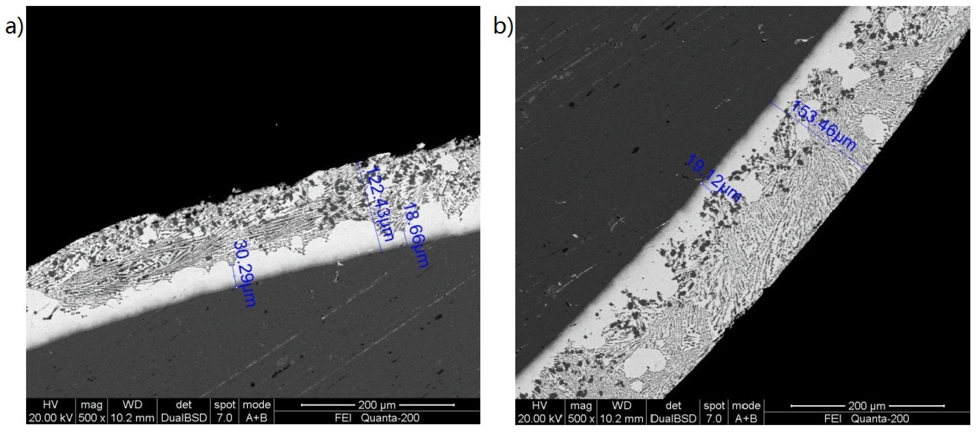
Figure 11.
Part of the brazed samples.

Figure 12.
Cross-sectional SEM morphologies of micro defects for the sample brazed at 550 °C (a), low magnification view (b), and micro voids (c).
Figure 12.
Cross-sectional SEM morphologies of micro defects for the sample brazed at 550 °C (a), low magnification view (b), and micro voids (c).
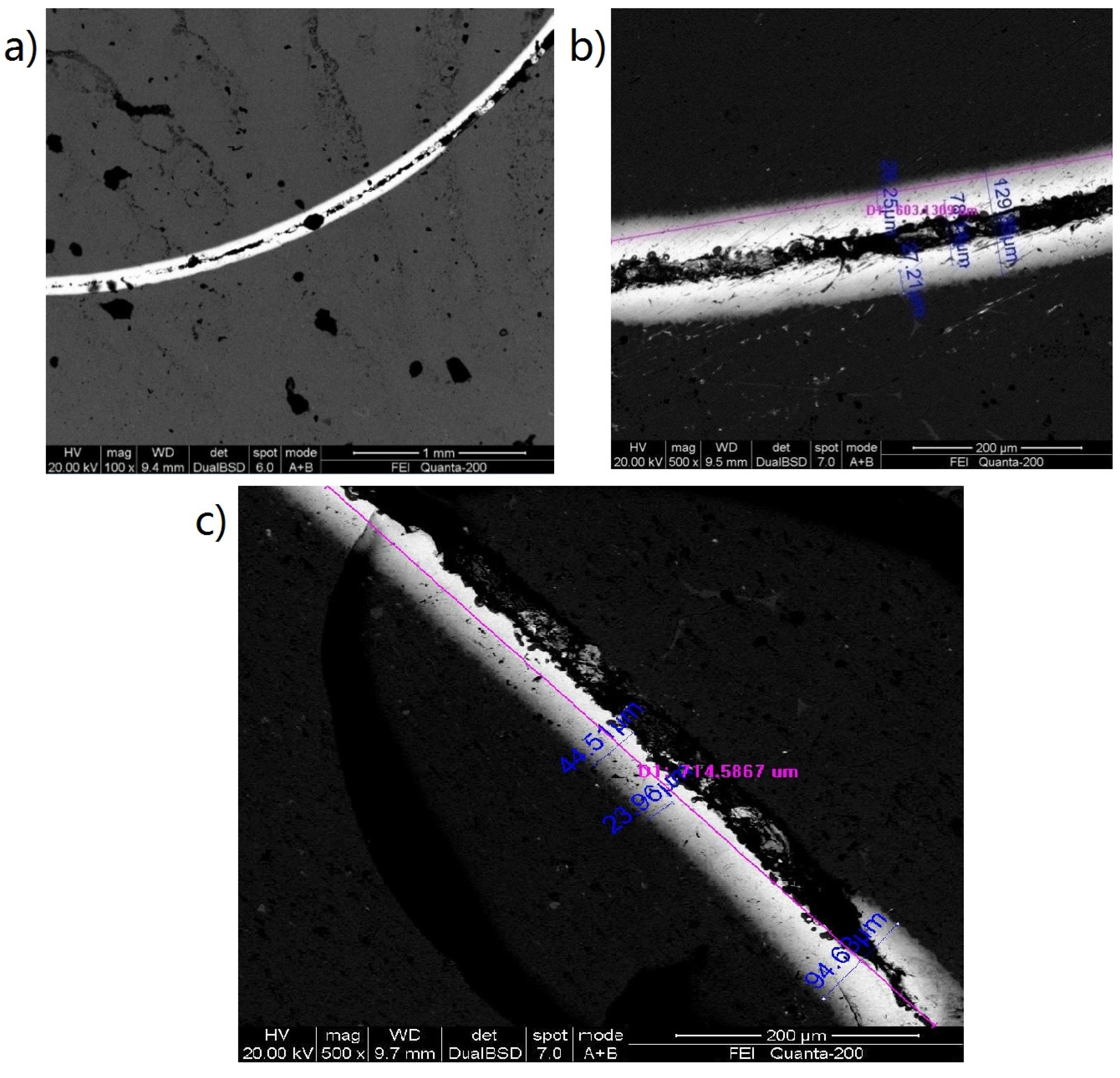
Figure 13.
Cross-sectional SEM morphologies of micro defects for the sample brazed at 535 °C.
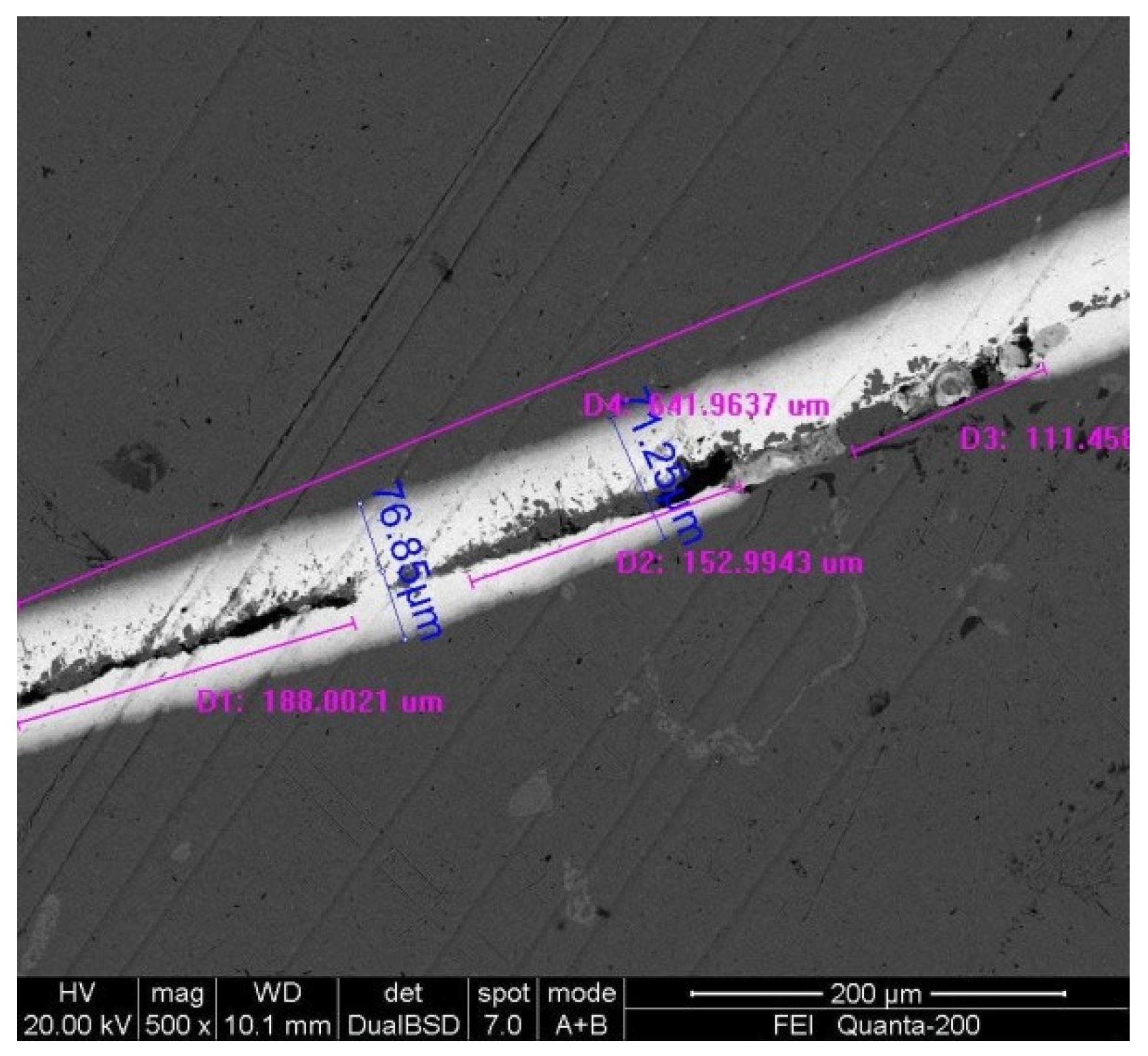
Figure 14.
Cross-sectional SEM morphologies of micro defects (a–c) and EDS spectrum (d) for the sample brazed for 30 min holding at 535 °C.
Figure 14.
Cross-sectional SEM morphologies of micro defects (a–c) and EDS spectrum (d) for the sample brazed for 30 min holding at 535 °C.
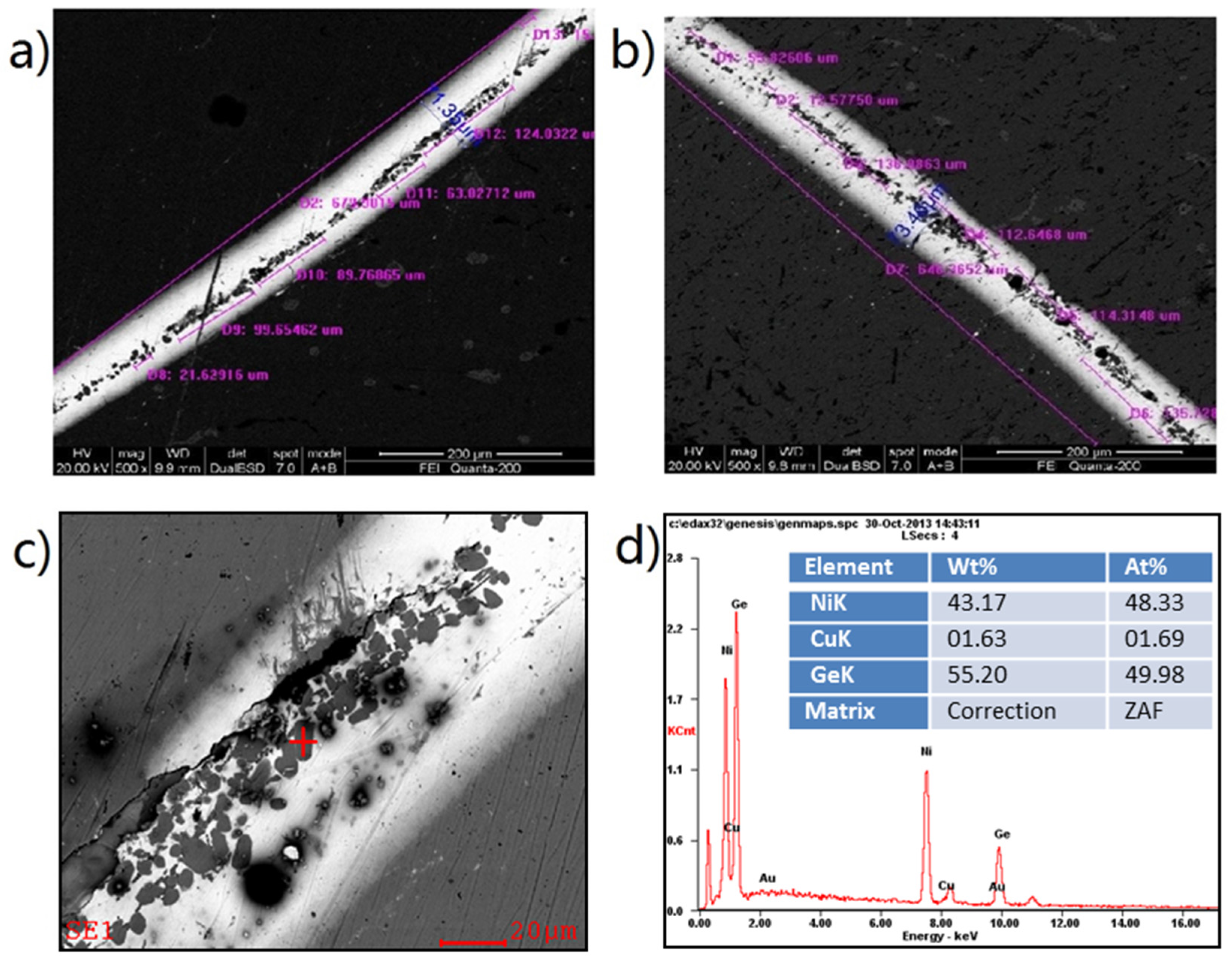
Figure 15.
The brazed samples with side solder feeding.

Figure 16.
Cross-sectional SEM morphologies (a,b) of the brazed interfacial microstructure for the sample brazed with side solder feeding.
Figure 16.
Cross-sectional SEM morphologies (a,b) of the brazed interfacial microstructure for the sample brazed with side solder feeding.

Table 1.
The shear strength for the samples brazed at different temperatures.
| Temperature/°C | 1# | 2# | 3# | 4# | 5# | 6# | Average Shear Strength/MPa | Standard Deviations |
|---|---|---|---|---|---|---|---|---|
| 500 | 83.1 | 84.4 | 86.5 | 81.8 | 78.4 | 74.9 | 81.52 | 4.22 |
| 535 | 85.3 | 92.7 | 87.5 | 84.2 | 83.9 | 88.7 | 87.05 | 3.35 |
| 550 | 52.7 | 43.8 | 50.2 | 48.6 | 53.1 | 47.9 | 49.38 | 3.45 |
Table 2.
The shear strength for the samples brazed for different holding times at 535 °C.
| Holding Time/min | 1# | 2# | 3# | 4# | 5# | 6# | Average Shear Strength/MPa | Standard Deviations |
|---|---|---|---|---|---|---|---|---|
| 10 | 85.3 | 92.7 | 87.5 | 84.2 | 83.9 | 88.7 | 87.05 | 3.35 |
| 20 | 66.6 | 69.9 | 64.7 | 68.2 | 74.8 | 69.2 | 68.90 | 3.44 |
| 30 | 58.4 | 57.9 | 57.4 | 61.8 | 60.2 | 57.6 | 58.88 | 1.75 |
Table 3.
The shear strength for the samples brazed with side solder feeding.
| 1# | 2# | 3# | 4# | 5# | 6# | Average Shear Strength/MPa | Standard Deviations |
|---|---|---|---|---|---|---|---|
| 102.2 | 105.7 | 102.5 | 100.3 | 101.9 | 105.1 | 102.95 | 2.05 |
Table 4.
The shear strength for the samples brazed with side solder feeding with large clearances.
| Sample | 1# | 2# | 3# | 4# | 5# | 6# | 7# | 8# | 9# | 10# | 11# | 12# | Average |
|---|---|---|---|---|---|---|---|---|---|---|---|---|---|
| Clearance/mm | 0.011 | 0.013 | 0.010 | 0.014 | 0.015 | 0.012 | 0.012 | 0.011 | 0.014 | 0.013 | 0.013 | 0.015 | 0.01275 |
| Shear strength/MPa | 102.3 | 103.1 | 98.8 | 99.6 | 105.3 | 102.7 | 105.3 | 103.6 | 104.2 | 101.8 | 103.1 | 104.2 | 102.83 |
© 2017 by the authors. Licensee MDPI, Basel, Switzerland. This article is an open access article distributed under the terms and conditions of the Creative Commons Attribution (CC BY) license (http://creativecommons.org/licenses/by/4.0/).
Share and Cite
MDPI and ACS Style
Li, Z.; Yi, Y.; He, D.; Lai, R. Interfacial Microstructure and Shear Strength of Brazed Cu-Cr-Zr Alloy Cylinder and Cylindrical Hole by Au Based Solder. Metals 2017, 7, 247. https://doi.org/10.3390/met7070247
AMA Style
Li Z, Yi Y, He D, Lai R. Interfacial Microstructure and Shear Strength of Brazed Cu-Cr-Zr Alloy Cylinder and Cylindrical Hole by Au Based Solder. Metals. 2017; 7(7):247. https://doi.org/10.3390/met7070247
Chicago/Turabian StyleLi, Zaihua, Youping Yi, Diqiu He, and Ruilin Lai. 2017. "Interfacial Microstructure and Shear Strength of Brazed Cu-Cr-Zr Alloy Cylinder and Cylindrical Hole by Au Based Solder" Metals 7, no. 7: 247. https://doi.org/10.3390/met7070247
Note that from the first issue of 2016, this journal uses article numbers instead of page numbers. See further details here.