Article

The Morphologies of Different Types of Fe2SiO4–FeO in Si-Containing Steel

The State Key Laboratory of Refractories and Metallurgy, Key Laboratory for Ferrous Metallurgy and Resources Utilization of Ministry of Education, Wuhan University of Science and Technology, Wuhan 430081, China
*
Author to whom correspondence should be addressed.
Metals 2017, 7(1), 8; https://doi.org/10.3390/met7010008
Submission received: 4 November 2016 / Revised: 14 December 2016 / Accepted: 26 December 2016 / Published: 29 December 2016

Abstract

:
Red scale defect is known to be mainly caused by net-like Fe2SiO4–FeO. In the present study, the morphology of Fe2SiO4–FeO in a Si-containing steel was investigated by simultaneous thermal analysis, high-temperature laser scanning confocal microscopy, scanning electron microscopy, and energy dispersive spectroscopy. Only liquid Fe2SiO4–FeO can form a net-like morphology. Liquid Fe2SiO4–FeO is classified into two types in this work. Type-1 liquid Fe2SiO4–FeO is formed by melting pre-existing solid Fe2SiO4–FeO that already exists before the melting point of Fe2SiO4–FeO. Type-2 liquid Fe2SiO4–FeO is formed at a temperature higher than the melting point of Fe2SiO4–FeO. The results show that type-1 liquid Fe2SiO4–FeO is more likely to form a net-like morphology than is type-2 liquid Fe2SiO4–FeO. The penetration depth of type-1 liquid Fe2SiO4–FeO is also larger at the same oxidation degree. Therefore, type-1 liquid Fe2SiO4–FeO should be avoided in order to eliminate red scale defect. Net-like Fe2SiO4–FeO may be alleviated by two methods: decreasing the oxygen concentration in the heating furnace before the melting point of Fe2SiO4–FeO is reached and increasing the reheating rate before the melting point. In addition, FeO is distributed with a punctiform or lamellar morphology on Fe2SiO4.

1. Introduction

Silicon (Si) is a common alloying element in advanced high strength steels [1,2,3], such as dual phase (DP) steel and transformation induced plasticity (TRIP) steel. However, the addition of Si often leads to red scale (mainly consisting of Fe2O3), a surface defect of hot rolled steels [4]. Some research has investigated the formation of red scale [5,6,7,8,9,10], commonly regarded as directly related to the presence of Fe2SiO4–FeO eutectic, which is formed by the combination of SiO2 and FeO [5,6]. The theoretical eutectic temperature (melting point) of Fe2SiO4–FeO is recognized as 1173 °C [7]. When the reheating temperature of slabs is above 1173 °C, the liquid Fe2SiO4–FeO penetrates into the external scale along the grain boundary of the scale and forms a net-like distribution [8,9]. If the subsequent descaling temperature is below 1173 °C, the liquid net-like Fe2SiO4 solidifies and firmly bonds the steel substrate and iron scale, making it difficult to completely remove the FeO layer during descaling. The remaining FeO scale is oxidized into red Fe2O3 (red scale defect) during the subsequent cooling and rolling processes [5,10].
Due to the close relationship between red scale and Fe2SiO4–FeO, some studies on Fe2SiO4–FeO in Si-containing steels have been carried out [11,12,13,14]. Yuan et al. [11] reported that the net-like morphology of Fe2SiO4–FeO is not obvious when the Si content is low. Mouayd et al. [12] and Suarez et al. [13] found that the amount and penetrative depth of Fe2SiO4–FeO increases with the Si content. In addition, He et al. [14] reported that the morphology of Fe2SiO4–FeO is blocky when the reheating temperature is below 1173 °C, because solid Fe2SiO4–FeO cannot penetrate into the external scale. However, when the reheating temperature is above 1173 °C, the morphology of Fe2SiO4–FeO is net-like. Net-like Fe2SiO4–FeO is well known to more easily lead to red scale compared with blocky Fe2SiO4–FeO.
In summary, red scale is mainly caused by net-like Fe2SiO4–FeO, and only liquid Fe2SiO4–FeO can form a net-like morphology. Thus, more attention should be given to the liquid Fe2SiO4–FeO. During the industrial reheating process, solid Fe2SiO4–FeO forms first before 1173 °C is reached and then melts into liquid at temperatures above 1173 °C. Besides, new liquid Fe2SiO4–FeO is gradually formed by the combination of SiO2 and FeO at temperatures above 1173 °C. Therefore, liquid Fe2SiO4–FeO can be classified into two types when the reheating temperature is above 1173 °C. One forms by the melting of pre-existing solid Fe2SiO4–FeO, which has already formed below 1173 °C. The other appears above 1173 °C which is liquid once it forms. The former is termed as type-1 liquid Fe2SiO4–FeO and the latter is termed as type-2 liquid Fe2SiO4–FeO. The biggest difference between two types of liquid Fe2SiO4–FeO is that type-1 liquid Fe2SiO4–FeO is solid before 1173 °C is reached, whereas type-2 liquid Fe2SiO4–FeO is liquid from the time it forms. The distributions and morphologies of both types of liquid Fe2SiO4–FeO may be different. It is necessary to study the difference in their morphologies due to the close relationship between red scale and liquid Fe2SiO4–FeO. Thus far, research on this subject has been rarely reported. The present study investigates the morphologies of different types of Fe2SiO4–FeO and provides a theoretical reference toward preventing red scale defect in Si-containing steels.

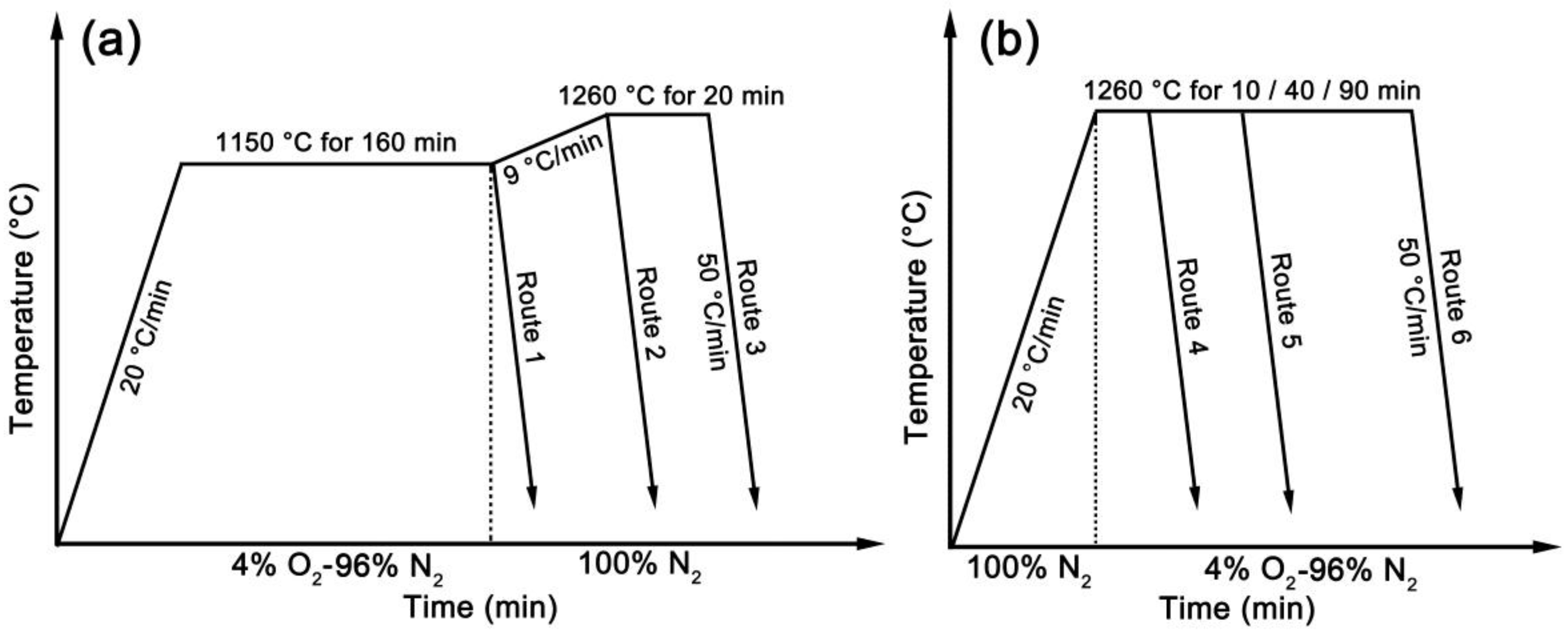
2. Materials and Methods

The chemical composition of the experimental steel is Fe-0.06C-1.21Si-1.4Mn-0.035Al-0.01P-0.001S (wt. %). The steel was obtained from a hot strip plant (WISCO, Wuhan, China). The oxidation tests were carried out on a Setaram Setsys Evo simultaneous thermal analyzer (STA, Setaram, Lyon, France). The dimensions of the samples were 15 mm × 10 mm × 3 mm. A hole with a diameter of 4 mm was drilled near the edge center of each sample for suspension in the oxidation chamber. The surfaces of all samples were polished to remove the scale before the tests. As shown in Figure 1, two types of experimental routes were designed. For Routes 1–3, a binary gas mixture of oxygen and nitrogen with an oxygen concentration of 4.0 vol % was introduced into the STA chamber at the beginning of the experiments to obtain a certain amount of solid Fe2SiO4–FeO. Then, the binary gas mixture was replaced with 100 vol % nitrogen at the end of isothermal holding. Route 1 was set to observe the morphology of solid Fe2SiO4–FeO. For Routes 2 and 3, only type-1 liquid Fe2SiO4–FeO forms at temperatures higher than the melting point of Fe2SiO4–FeO. For Routes 4–6, a binary gas mixture of oxygen and nitrogen with an oxygen concentration of 4.0 vol % was not introduced into the STA chamber until the isothermal holding at 1260 °C. Thus, only type-2 liquid Fe2SiO4–FeO forms. Different isothermal holding time was set to investigate the effect of holding time on the morphology of Fe2SiO4–FeO. In short, the morphology of solid Fe2SiO4–FeO can be observed in Route 1 and the morphology of type-1 liquid Fe2SiO4–FeO can be observed in Routes 2 and 3. The morphology of type-2 liquid Fe2SiO4–FeO can be observed in Routes 4–6. There is no standard procedure of heating and oxidation routes. The experimental procedures are set to observe the separate morphology of different types of Fe2SiO4–FeO. The oxidizing atmosphere (4.0 vol % O2-96.0 vol % N2) is similar to that in the industrial reheating furnace. The accuracy of temperature measurement is ±0.5 °C. The mass gain of the samples and the temperature were digitally recorded during the whole oxidation processes.
After the oxidation tests, the samples were molded in resins at room temperature to protect the integrity of the oxide scale. Cross sections of the mounted samples were ground and polished. The microstructures of the oxide scale were observed by using a Nova 400 Nano scanning electron microscope (SEM, FEI, Hillsboro, OR, USA) operated at an accelerating voltage of 20 kV. The components of the oxide scale were analyzed with an energy dispersive spectrometer (EDS, OIMS, Oxford, UK). In addition, high-temperature laser scanning confocal microscopy (LSCM) was used for in situ observation of the melting process of Fe2SiO4–FeO. Samples for LSCM were selected from oxidized specimens and machined into a cylinder 6 mm in diameter and 4 mm in height. The investigations were conducted on a VL2000DXSVF17SP LSCM (lasertec, Yokohama, Japan). The specimen chamber was initially evacuated to 6 × 10⁻³ Pa before heating and argon was used to protect the specimens from surface oxidation. The sample was heated to 1260 °C at 20 °C/min and held for 10 min, followed by cooling to room temperature at 50 °C/min. Fifteen photographs per second were taken during the LSCM experiments.

3. Results and Discussions

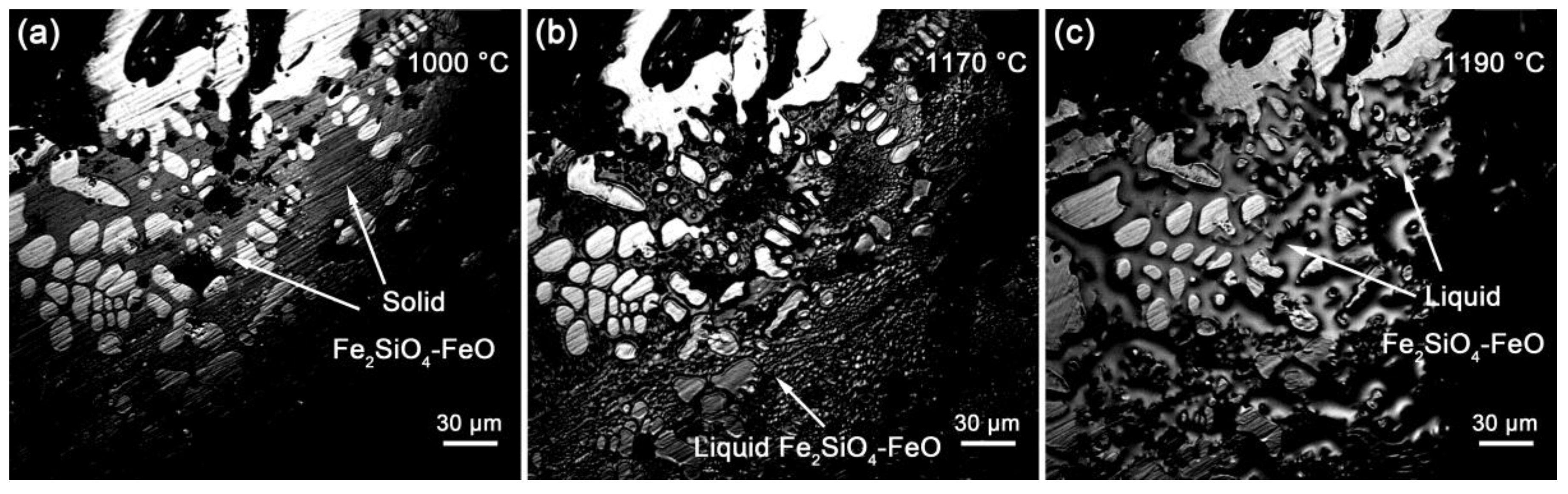
3.1. In Situ Observation

Route 1 and Routes 2 and 3 are designed for observing the morphologies of solid Fe2SiO4–FeO and type-1 liquid Fe2SiO4–FeO, respectively; thus, it is necessary to ensure that Fe2SiO4–FeO does not melt at 1150 °C. The theoretical melting point of Fe2SiO4–FeO is 1173 °C. However, the real value is influenced by the composition of the steel. The melting process of Fe2SiO4–FeO was observed in Figure 2. Fe2SiO4–FeO is solid at 1000 °C (Figure 2a). Solid Fe2SiO4–FeO begins to melt at 1170 °C (Figure 2b), so that the real melting point of Fe2SiO4–FeO is 1170 °C for the tested steel. Figure 2c indicates that Fe2SiO4–FeO completely melts at 1190 °C. Therefore, Fe2SiO4–FeO is always solid in Route 1 and only type-1 liquid Fe2SiO4–FeO forms after 1170 °C in Routes 2 and 3 (type-2 liquid Fe2SiO4–FeO does not form due to nitrogen protection).

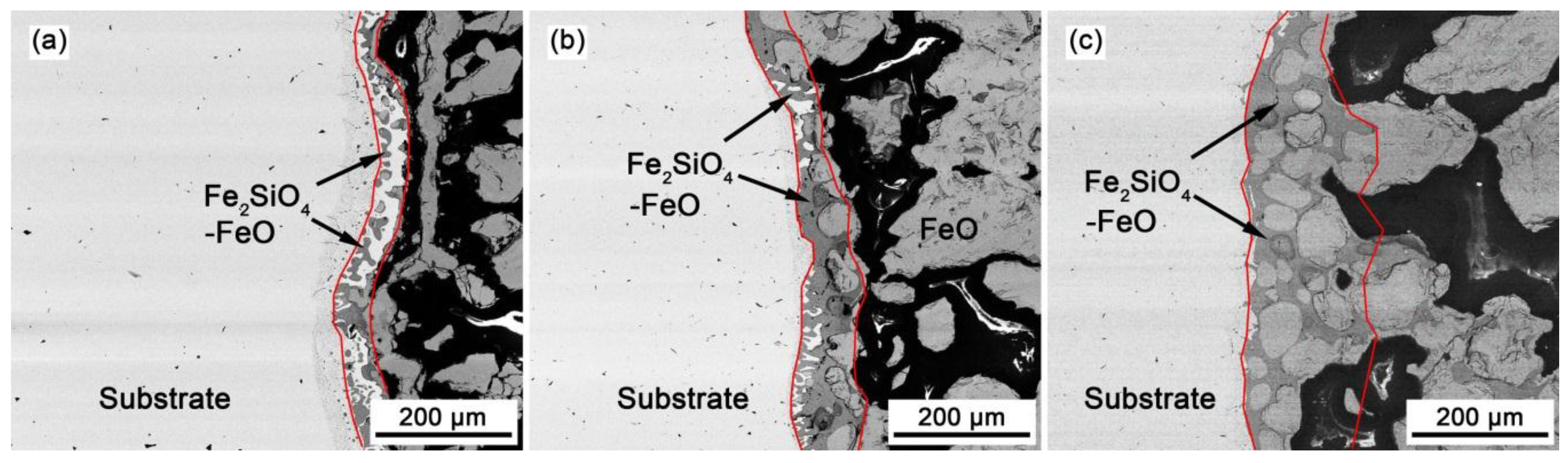
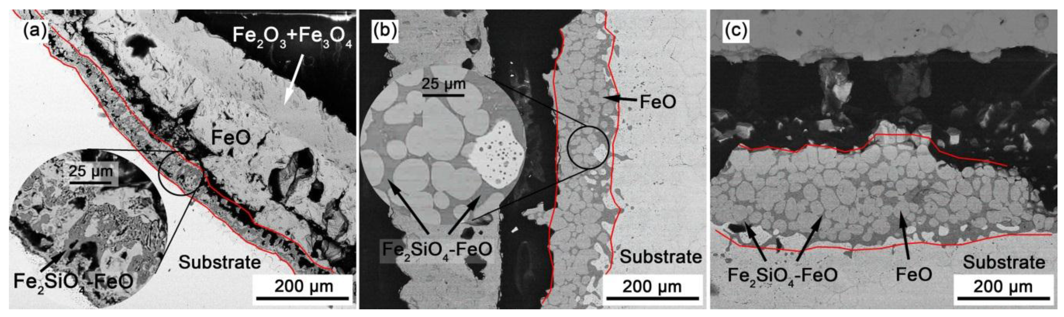
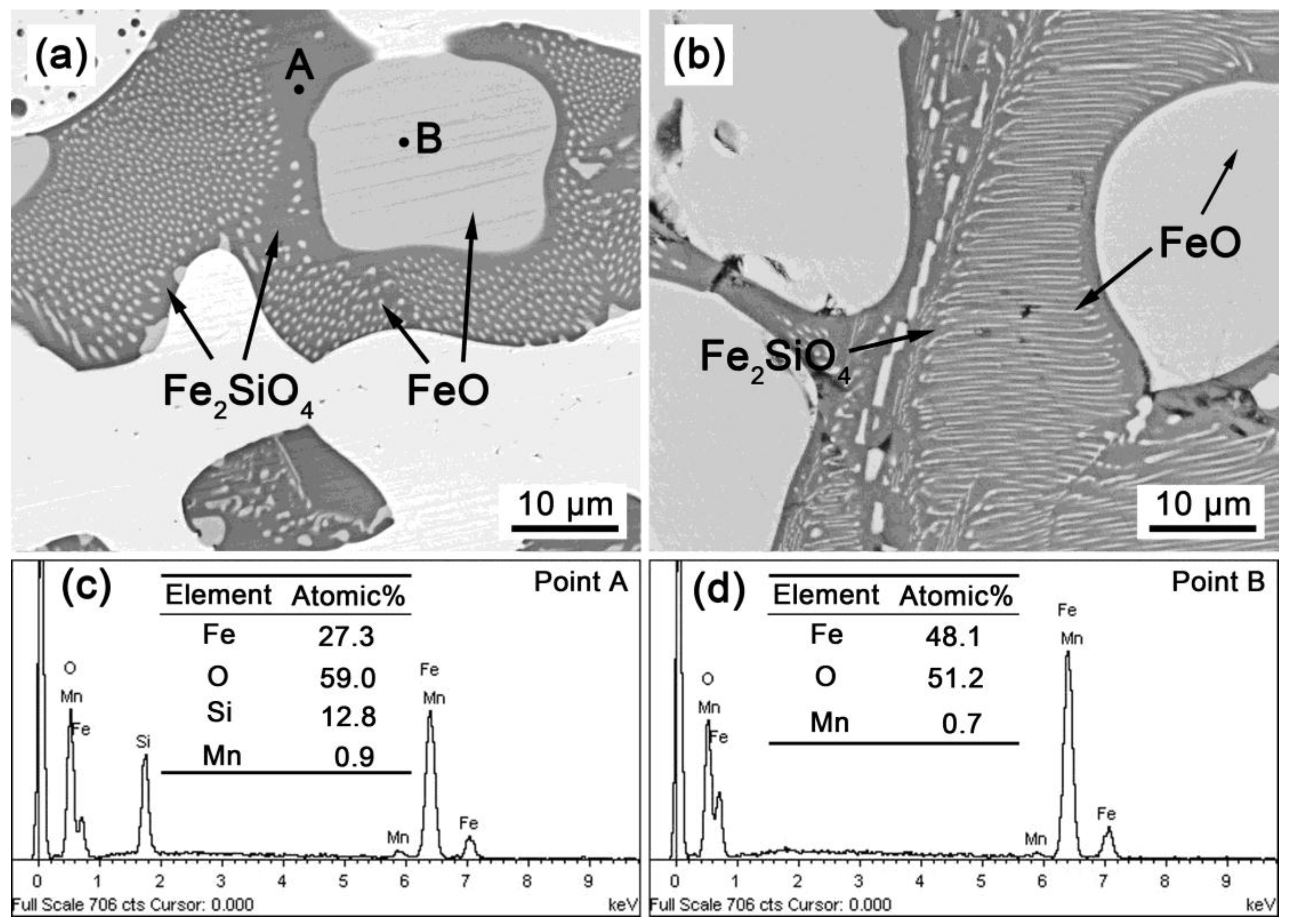
3.2. SEM Observations

Previous studies have confirmed that the iron scale in this steel contains Fe2O3, Fe3O4, FeO, and Fe2SiO4 [11,14,15]. The intimal scale consists of Fe2SiO4 and FeO. Figure 3 shows the typical morphology of Fe2SiO4–FeO in Routes 1–3. The Fe2SiO4–FeO layers are marked by red lines. When the heating temperature is 1150 °C (Route 1), Fe2SiO4–FeO is blocky and dispersively distributed (Figure 3a); thus, solid Fe2SiO4–FeO is not net-like even when the holding time is as long as 160 min. Figure 3b shows that a large amount of net-like Fe2SiO4–FeO appears during Route 2, in which the melting time of the preexisting solid Fe2SiO4–FeO is 10 min; this indicates that the morphology of Fe2SiO4–FeO changes quickly and significantly after melting. Therefore, type-1 liquid Fe2SiO4–FeO can quickly form a net-like morphology within 10 min. When the melting time increases to 30 min, Fe2SiO4–FeO penetrates into a deeper area (Figure 3c).
The distribution of FeO in Fe2SiO4–FeO has been rarely reported. Figure 4 shows the typical distribution of Fe2SiO4–FeO. According to EDS results (Figure 4c,d), the darker scale is Fe2SiO4 and the lighter one is FeO. Fe2SiO4 surrounds FeO. Interestingly, FeO is distributed on Fe2SiO4 with a punctiform (Figure 4a) or lamellar morphology (Figure 4b), which is similar to the morphology of pearlite in steel. A possible mechanism for the structure of Fe2SiO4–FeO may be that, during the cooling process, FeO separates out from Fe2SiO4–FeO in the form of a lamella or sphere due to the diffusion of Fe, O, and Si elements. Lamellar FeO has a larger surface area and interfacial energy compared with punctiform FeO. The nonuniform concentrations of Si, O, and Fe lead to two different morphologies of FeO.
Figure 5 shows the typical morphology of Fe2SiO4–FeO for Routes 4–6, in which only type-2 liquid Fe2SiO4–FeO forms during isothermal holding at 1260 °C. Figure 5a shows that type-2 liquid Fe2SiO4–FeO is blocky after 10 min of oxidation. As the time increases to 40 min, the penetration depth increases, but Fe2SiO4–FeO is still blocky (Figure 5b). When the oxidation time increases to 90 min, the net-like morphology of Fe2SiO4–FeO appears. Therefore, liquid Fe2SiO4–FeO is not necessarily net-like, and type-2 liquid Fe2SiO4–FeO does not form a net-like morphology before 40 min.
The total mass gain recorded in the oxidation experiments represents the oxidation degree. Figure 6a shows the total mass gains for Routes 1–6. The oxidation degrees are almost the same for Routes 1–3 because of the same oxidation temperature and time (Note that the samples were not oxidized after isothermal holding at 1150 °C in Routes 1–3). The oxidation degrees for Routes 2, 3, and 5 are similar. However, the morphology of Fe2SiO4–FeO is significantly different. With similar oxidation degree, type-1 liquid Fe2SiO4–FeO (Routes 2 and 3; Figure 3b,c) is obviously net-like, whereas type-2 Fe2SiO4–FeO is blocky (Route 5; Figure 5b). Note that type-2 Fe2SiO4–FeO can also form a net-like morphology (Figure 5c); however, it requires a much higher oxidation degree compared with type-1 Fe2SiO4–FeO. In addition, the oxidation degree in Route 6 is larger than that in Route 3, whereas the penetration depth of Fe2SiO4–FeO in Route 6 (Figure 5c) is smaller than that in Route 3 (Figure 3c), indicating that type-1 liquid Fe2SiO4–FeO is more likely to form a net-like morphology. The penetration depth of Fe2SiO4–FeO is measured by using the software Image-Pro Plus 6.0 and then normalized by dividing the total mass gain (normalized penetration depth = real penetration depth/total mass gain), as is shown in Figure 6b. The normalized penetration depth of type-1 liquid Fe2SiO4–FeO is larger than that of type-2 liquid Fe2SiO4–FeO, indicating that type-1 liquid Fe2SiO4 penetrates more easily into the external scale. Moreover, the penetration depth of solid Fe2SiO4–FeO is much smaller than that of liquid Fe2SiO4–FeO.
The above results can be interpreted as follows. The Pilling–Bedworth ratio (PBR) is the ratio of the oxide volume to the consumed metal volume [16]. The PBR of Fe oxide or Si oxide is larger than 1 because the volume of the oxide is larger than that of the consumed metal, leading to a compressive stress in the oxide [8]. Liquid Fe2SiO4–FeO can penetrate into outer scale under the effect of this compressive stress, so that net-like morphology of Fe2SiO4–FeO forms after a certain time. The scale adjacent to Fe2SiO4–FeO (whether solid or liquid) is solid. The compressive stress between two solids should be larger than that between a solid and a liquid; thus, solid Fe2SiO4–FeO should be subjected to a larger stress compared with liquid Fe2SiO4–FeO. When preexisting solid Fe2SiO4–FeO melts into type-1 liquid Fe2SiO4–FeO, it can quickly penetrate into an outer place under a larger compressive stress. On the other hand, type-2 liquid Fe2SiO4–FeO is subjected to a smaller stress because it is liquid when formed; thus, its penetration rate is smaller. In addition, a large amount of Fe2SiO4–FeO has accumulated before the penetration of type-1 liquid Fe2SiO4–FeO, whereas the penetration and formation of type-2 liquid Fe2SiO4–FeO take place simultaneously. Therefore, it is easier for type-1 liquid Fe2SiO4–FeO to penetrate into the scale.
Red scale defect is well known to be caused by the net-like morphology of Fe2SiO4–FeO [5,10]. Type-1 liquid Fe2SiO4–FeO is more likely to form a net-like morphology, so that it should be avoided in order to eliminate red scale defect. The amount of type-1 liquid Fe2SiO4–FeO can be decreased by hindering the formation of solid Fe2SiO4–FeO. One way to do this is by decreasing the oxygen concentration in the heating furnace before the melting point of Fe2SiO4–FeO (1170 °C in the present study) is reached [17,18]. In addition, increasing the reheating rate before 1170 °C can also decrease the amount of solid Fe2SiO4–FeO due to a shorter oxidation time.

4. Conclusions

Liquid Fe2SiO4–FeO is classified into two types. The present study investigates the difference in morphology between these two types of liquid Fe2SiO4–FeO. The results show that, compared with type-2 liquid Fe2SiO4–FeO, type-1 liquid Fe2SiO4–FeO is more likely to form a net-like morphology. The penetration depth of type-1 liquid Fe2SiO4–FeO is also larger at the same oxidation degree. Red scale defect is known to be caused by the net-like Fe2SiO4–FeO. Therefore, type-1 liquid Fe2SiO4–FeO should be avoided in order to eliminate red scale defect. Net-like Fe2SiO4–FeO may be alleviated by two methods: decreasing the oxygen concentration in the heating furnace and increasing the reheating rate before the melting point of Fe2SiO4–FeO is reached. In addition, FeO is distributed with a punctiform or lamellar morphology on Fe2SiO4.

Acknowledgments

The authors gratefully acknowledge the financial supports from National Natural Science Foundation of China (NSFC) (No. 51274154) and the National High Technology Research and Development Program of China (No. 2012AA03A504).

Author Contributions

Guang Xu and Mingxing Zhou conceived and designed the experiments; Mingxing Zhou performed the experiments; Mingxing Zhou, Haijiang Hu, and Qing Yuan analyzed the data; Junyu Tian contributed materials tools; Mingxing Zhou wrote the paper.

Conflicts of Interest

The authors declare no conflict of interest. The founding sponsors had no role in the design of the study; in the collection, analyses, or interpretation of data; in the writing of the manuscript; or in the decision to publish the results.

Abbreviations

The following abbreviations are used in this manuscript:
STAsimultaneous thermal analyzer
LSCMhigh temperature laser scanning confocal microscopy
SEMscanning electron microscope

References

  1. Hu, H.J.; Xu, G.; Wang, L.; Xue, Z.L.; Zhang, Y.; Liu, G. The effects of Nb and Mo addition on transformation and properties in low carbon bainitic steels. Mater. Des. 2015, 84, 95–99. [Google Scholar] [CrossRef]
  2. Hu, H.J.; Xu, G.; Zhou, M.X.; Yuan, Q. Effect of Mo Content on Microstructure and Property of Low-Carbon Bainitic Steels. Metals 2016, 6, 173–182. [Google Scholar] [CrossRef]
  3. Zhou, M.X.; Xu, G.; Wang, L.; Yuan, Q. The Varying Effects of Uniaxial Compressive Stress on the Bainitic Transformation under Different Austenitization Temperatures. Metals 2016, 6, 119–130. [Google Scholar] [CrossRef]
  4. Takeda, M.; Onishi, T. Oxidation behavior and scale properties on the Si containing steels. Mater. Sci. Forum. 2006, 522, 477–488. [Google Scholar] [CrossRef]
  5. Okada, H.; Fukagawa, T.; Ishihara, H. Prevention of red scale formation during hot rolling of steels. ISIJ Int. 1995, 35, 886–891. [Google Scholar] [CrossRef]
  6. Yang, Y.L.; Yang, C.H.; Lin, S.N.; Chen, C.H.; Tsai, W.T. Effect of Si and its content on the scale formation on hot-rolled steel strips. Mater. Chem. Phys. 2008, 112, 566–571. [Google Scholar] [CrossRef]
  7. Liu, X.J.; Cao, G.M.; He, Y.Q.; Jia, T.; Liu, Z.Y. Effect of temperature on scale morphology of Fe-1.5Si Alloy. J. Iron Steel Res. Int. 2013, 20, 73–78. [Google Scholar] [CrossRef]
  8. Garnaud, G.; Rapp, R.A. Thickness of the oxide layers formed during the oxidation of iron. Oxid. Met. 1977, 11, 193–198. [Google Scholar] [CrossRef]
  9. Liu, X.J.; Cao, G.M.; Nie, D.M.; Liu, Z.Y. Mechanism of black strips generated on surface of CSP hot-rolled silicon steel. J. Iron. Steel Res. Int. 2013, 20, 54–59. [Google Scholar] [CrossRef]
  10. Fukagawa, T.; Okada, H.; Maeharara, Y. Mechanical of red scale defect formation in Si-added hot-rolled steels. ISIJ Int. 1994, 34, 906–911. [Google Scholar] [CrossRef]
  11. Yuan, Q.; Xu, G.; Zhou, M.X.; He, B. The effect of the Si content on the morphology and amount of Fe2SiO4 in low carbon steels. Metals 2016, 6, 94–103. [Google Scholar] [CrossRef]
  12. Mouayd, A.A.; Koltsov, A.; Sutter, E.; Tribollet, B. Effect of silicon content in steel and oxidation temperature on scale growth and morphology. Mater. Chem. Phys. 2014, 143, 996–1004. [Google Scholar] [CrossRef]
  13. Suarez, L.; Schneider, J.; Houbaert, Y. High-Temperature oxidation of Fe-Si alloys in the temperature range 900–1250 °C. Defect. Diffus. Forum. 2008, 273–276, 661–666. [Google Scholar] [CrossRef]
  14. He, B.; Xu, G.; Zhou, M.X.; Yuan, Q. Effect of Oxidation Temperature on the Oxidation Process of Silicon-Containing Steel. Metals 2016, 6, 137–145. [Google Scholar] [CrossRef]
  15. Yuan, Q.; Xu, G.; Zhou, M.X.; He, B. New insights into the effects of silicon content on the oxidation process in silicon-containing steels. Int. J. Min. Met. Mater. 2016, 23, 1–8. [Google Scholar] [CrossRef]
  16. Staettle, R.W.; Fontana, M.G. Advances in Corrosion Science and Technology; Springer: New York, NY, USA, 1974; pp. 239–356. [Google Scholar]
  17. Abuluwefa, H.; Guthrie, R.I.L.; Ajersch, F. The Effect of Oxygen Concentration on the Oxidation of Low-Carbon Steel in the Temperature Range 1000 to 1250 °C. Oxid. Met. 1996, 46, 423–440. [Google Scholar] [CrossRef]
  18. Chen, R.Y.; Yuen, W.Y.D. Review of the High-Temperature Oxidation of Iron and Carbon Steels in Air or Oxygen. Oxid. Met. 2003, 59, 433–468. [Google Scholar] [CrossRef]
Figure 1. Oxidation experiment routes: (a) Routes 1–3; (b) Routes 4–6.
Metals 07 00008 g001
Figure 2. In situ observation of the melting process of Fe2SiO4–FeO: (a) 1000 °C, before melting; (b) 1170 °C, at the start of melting; (c) 1190 °C, after melting.
Metals 07 00008 g002
Figure 3. The typical morphology of Fe2SiO4–FeO in Routes 1-3: (a) Route 1, without melting; (b) Route 2, melting for 10 min; (c) Route 3, melting for 30 min.
Metals 07 00008 g003
Figure 4. (a,b) The typical distribution of Fe2SiO4–FeO; (c) The energy spectra of Point A (Fe2SiO4); (d) The energy spectra of Point B (FeO).
Metals 07 00008 g004
Figure 5. The typical morphology of Fe2SiO4–FeO for Routes 4–6: (a) Route 4, 1260 °C for 10 min; (b) Route 5, 1260 °C for 40 min; (c) Route 6, 1260 °C for 90 min.
Metals 07 00008 g005
Figure 6. (a) The total mass gain for Routes 1–6. (b) The normalized penetration depth of Fe2SiO4–FeO.
Metals 07 00008 g006

