Article

Effect of Al Hot-Dipping on High-Temperature Corrosion of Carbon Steel in N2/0.1% H2S Gas

School of Advanced Materials Science and Engineering, Sungkyunkwan University, Suwon 16419, Korea
*
Author to whom correspondence should be addressed.
Metals 2016, 6(2), 38; https://doi.org/10.3390/met6020038
Submission received: 11 January 2016 / Revised: 3 February 2016 / Accepted: 5 February 2016 / Published: 17 February 2016
(This article belongs to the Special Issue Oxidation of Metals)

Abstract

:
High-temperature corrosion of carbon steel in N2/0.1% H2S mixed gas at 600–800 °C for 50–100 h was studied after hot-dipping in the aluminum molten bath. Hot-dipping resulted in the formation of the Al topcoat and the Al-Fe alloy layer firmly adhered on the substrate. The Al-Fe alloy layer consisted primarily of a wide, tongue-like Al5Fe2 layer and narrow Al3Fe layer. When corroded at 800 °C for 100 h, the Al topcoat partially oxidized to the protective but non-adherent α-Al2O3 layer, and the interdiffusion converted the Al-Fe alloy layer to an (Al13Fe4, AlFe3)-mixed layer. The interdiffusion also lowered the microhardness of the hot-dipped steel. The α-Al2O3 layer formed on the hot-dipped steel protected the carbon steel against corrosion. Without the Al hot-dipping, the carbon steel failed by forming a thick, fragile, and non-protective FeS scale.

Graphical Abstract

1. Introduction

The H2S gas comes off as a by-product during processing in oil refineries, petrochemical plants and fossil-fired power plants. It dissociates into sulfur and hydrogen, and embrittles and corrodes the steel seriously by forming FeS scales incorporated with some hydrogen to dangerously shorten the service life of the steel. FeS is entirely non-protective, and grows fast owing to its high non-stoichiometry and low melting point [1]. Hydrogen released from the H2S gas ingresses in the scale and steel interstitially as molecular hydrogen (H), generates lattice point defects, forms hydrogen clusters, and thereby increases the corrosion rate greatly. Since steels cannot resist the H2S corrosion at high temperatures, they need to be coated. Al hot-dipping is an effective, inexpensive and simple anti-corrosion coating technique for steels [2]. The hot-dipped coating consists of the Al-rich topcoat and the inner Al-Fe alloy layer that is composed of an outer minor Al3Fe layer (near topcoat side) and an inner major Al5Fe2 layer (near steel substrate side). An irregular tongue- or finger-like morphology develops between the inner major Al5Fe2 layer and the steel substrate [3,4]. The Al hot-dipping drastically improved the oxidation resistance of steels by forming the highly protective α-Al2O3 layer upon exposure to air at high temperatures [5,6,7]. However, the corrosion resistance of Al-coated carbon steels in the H2S-containing gas was not yet adequately studied. The purpose of this study was to investigate the corrosion behavior of the Al hot-dipped carbon steel under N2/0.1% H2S mixed gas at high temperatures in order to utilize the Al hot-dipped steel in the hostile H2S-containing environments.

2. Experimental Procedure

A medium carbon steel plate with a nominal composition of Fe-0.44 C-0.30 Mn-0.25 Si-0.019 S-0.016 P (wt. %) was cut to 80 × 20 × 2 mm3 size coupons, ground using SiC sand paper No. 1200, cleaned ultrasonically in alcohol, subjected to the liquid flux solution consisting of 20 vol. % KCl and AlF3 in 4:1 weight ratio in water. After drying, the coupons were immersed in the pure molten Al bath on top of which a solid flux (KCl + NaCl + AlF3 in 2:2:1 in weight ratio) was spread to protect the molten Al bath from oxidation. The Al hot-dipped steel was pulled out, cooled to room temperature in air, further cleaned using 5 vol. % HNO3 solution to remove any flux adhered on the aluminized surface, placed in a quartz tube furnace and exposed at 600–800 °C for up to 100 h in N2/0.1% H2S-mixed gas. After the corrosion tests the Al hot-dipped steel specimens were examined by an optical microscope (OM; Leica DM2700, Leica Microsystems, Switzerland), a scanning electron microscope (SEM, Hitachi S3000-N, Tokyo, Japan) equipped with an energy dispersive spectroscope (EDS; Horiba Ex-220, Kyoto, Japan) and a high power X-ray diffractometer (XRD; Bruker D8 Advance, Karlsruhe, Germany) using Cu-Kα radiation operating at 40 kV and 300 mA. Before analyzing the results using above microstructural techniques, the cross-sections were etched in a reagent consisting of 5% nitric acid, 5% sulfuric acid, and 0.1% hydrofluoric acid. The Vickers microhardness (Microhardness Tester, Mitutoyo MVK-H2, Kanagawa, Japan) of the Al hot-dipped steel specimen was measured along the coating depth at room temperature under an indentation load of 100 g for 5 s, with an average indentation interval of 50 µm.

3. Results and Discussion

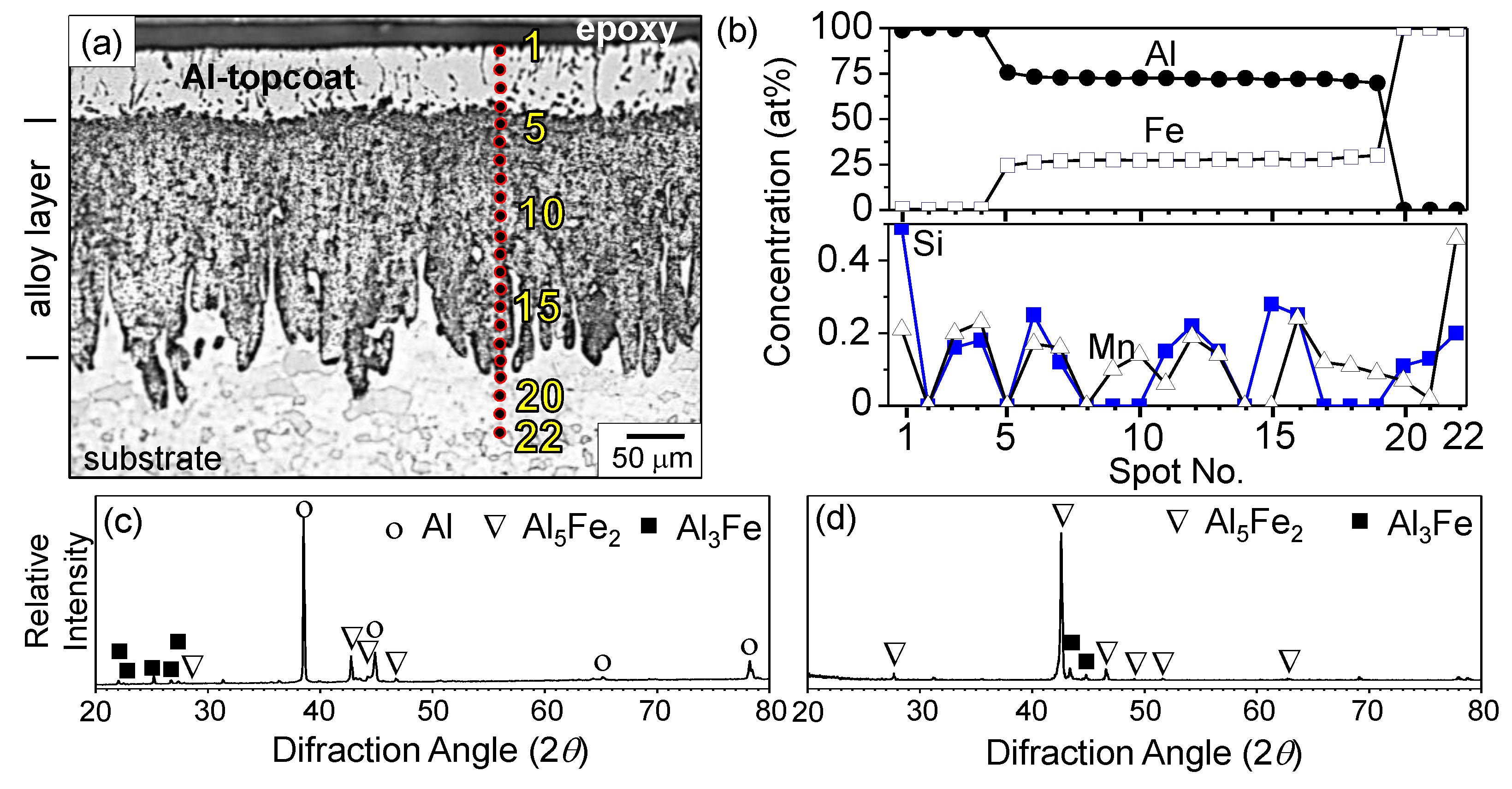
Figure 1 shows OM/EDS/XRD results of the Al hot-dipped carbon steel. 
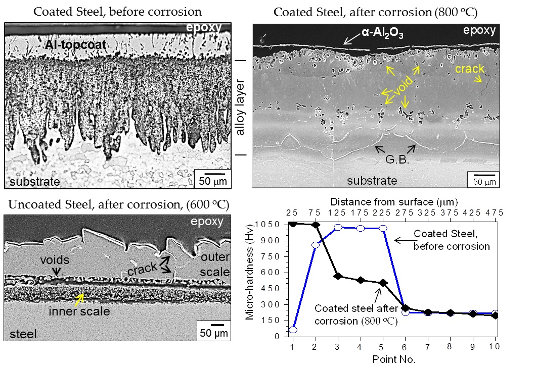
Figure 1a indicates that the hot-dipped coating consists of the Al topcoat with a thickness of about 50–60 µm and the Al-Fe alloy layer with a thickness of 170–230 µm. The characteristic finger- or tongue-like morphology was seen between the Al-Fe alloy layer with the columnar microstructure and the steel substrate having equiaxed grains [8]. It originated from the fast inward diffusion of Al during hot-dipping through the orthorhombic Al5Fe2 with 30% vacancies along the c-axis [4], or from the atomic size mismatch between Al (atomic radius; 0.143 nm) and Fe (atomic radius; 0.126 nm) [9]. Figure 1b indicates the EDS concentration spot analysis (at. %). Spots 1–4, 5–19 and 20–22 corresponded to the Al topcoat, Al-Fe alloy layer, and the steel substrate, respectively. The Al/Fe compositional ratios (at. %) at spots 5–6 and 7–19 were 2.9 and 2.6, respectively, suggesting that mainly Al3Fe and Al5Fe2 were formed in the alloy layer between the topcoat and the substrate. SEM/EDS analysis indicated that no aluminum was detected below spot 19. The alloying elements such as Mn and Si were detected in a small amount inside the coating (Figure 1b), implying their dissolution in the coating. The intensity of diffraction patterns decreased in the order of Al, Al5Fe2, and Al3Fe in Figure 1c, and decreased in the order of Al5Fe2 and Al3Fe in Figure 1d. This indicated that the Al-Fe alloy layer that existed below the Al topcoat was composed of Al5Fe2 as the major phase, and Al3Fe as the minor one [3,4].
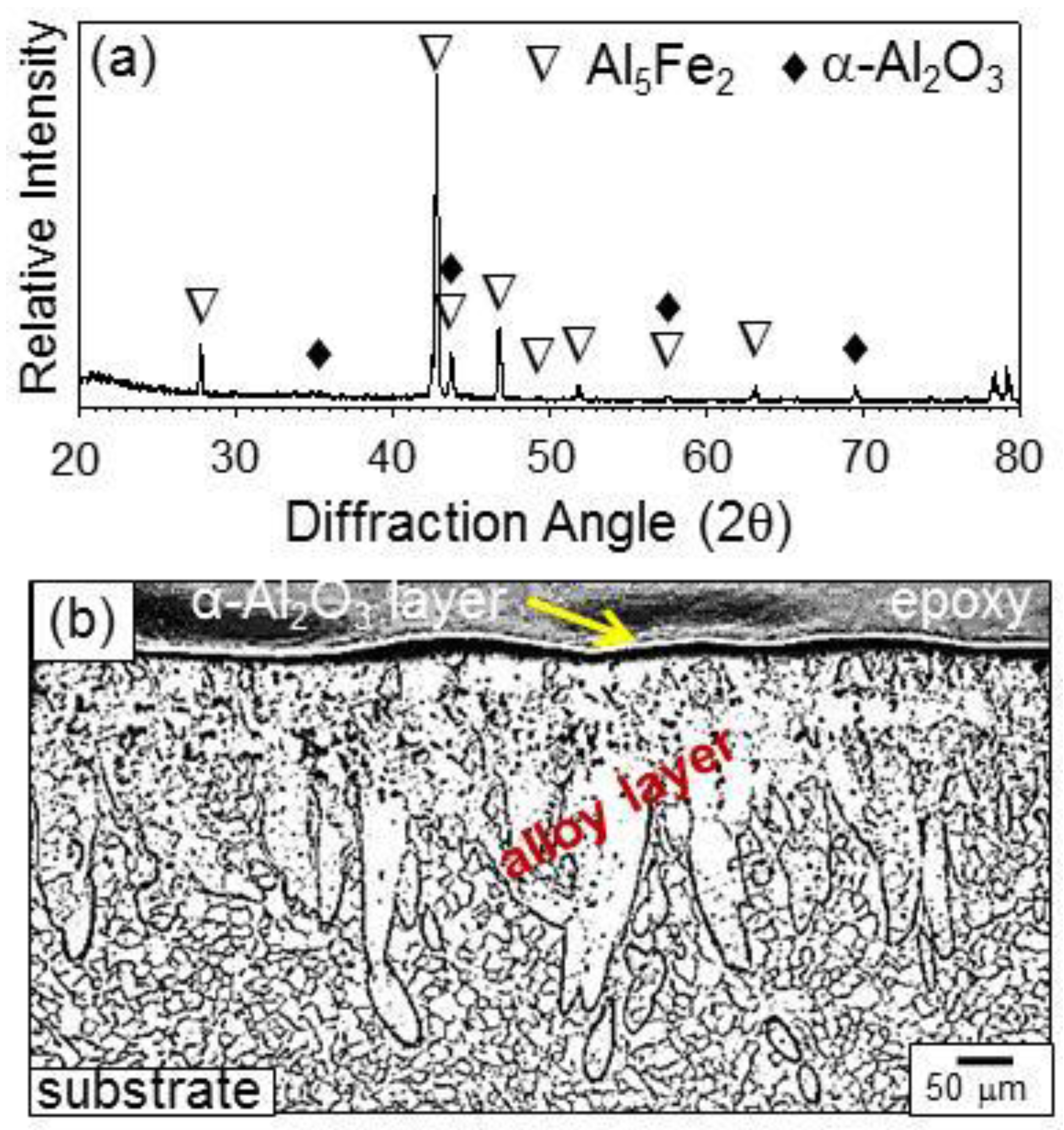
Figure 2 shows XRD/OM results of the Al hot-dipped carbon steel after corrosion at 600 °C for 50 h. In Figure 2a, α-Al2O3 and Al5Fe2 were detected as the minor and major phases, respectively. The Al topcoat partially oxidized to α-Al2O3, and leftover (i.e., uncorroded) aluminum topcoat along with the underlying Al3Fe layer transformed to the Al5Fe2 not only due to the outward diffusion of Fe (from the substrate to the surface) but also due to the inward diffusion of Al (from the coating towards the interior) during heating under N2/0.1% H2S gas. The oxygen source for the formation of α-Al2O3 was the impurity of oxygen in the N2/0.1% H2S gas. The α-Al2O3 scale with a thickness of about 5 µm, the underlying Al5Fe2-rich alloy layer, and the substrate were shown in Figure 2b. The α-Al2O3 scale was non-adherent due to the incorporation of sulfur and hydrogen from H2S and the mismatch of thermal expansion coefficients between the scale and the alloy layer.
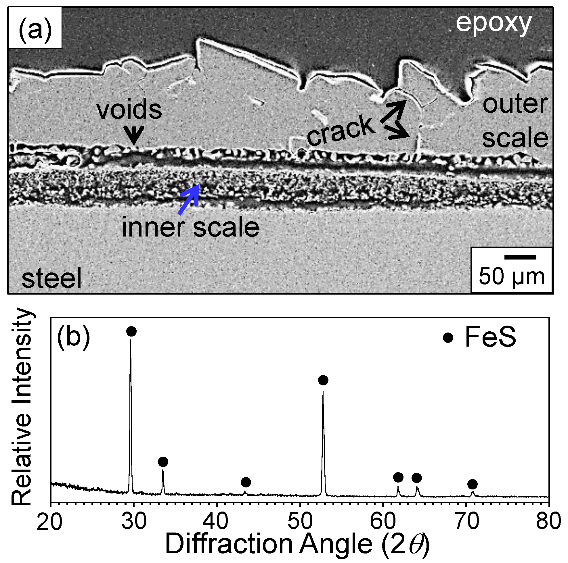
Without aluminum hot-dipping, the carbon steel was corroded seriously, as shown in Figure 3. The corrosion condition selected for the uncoated steel was the same as described in Figure 2 (i.e., 600 °C for 50 h) in order to find the effect of hot-dip aluminizing. The scale formed on the uncoated steel was ~165–200 µm thick (Figure 3a), and consisted of FeS (Figure 3b). The scale was fragile and easily detached from the matrix owing to the incorporation of sulfur and hydrogen from H2S. Moreover, excessively large growth stress had arisen due to the formation of a thick scale, and the thermal stresses generated during corrosion and the subsequent cooling stage. Since FeS has a defect structure of Fe1−xS (x = 0–0.2), it grows rapidly through the outward diffusion of Fe2+ ions, leaving Kirkendall voids behind [1]. Hence, numerous voids formed at the bottom of the FeS scale, which could act as stress concentration sites to facilitate the scale spallation (Figure 3a).
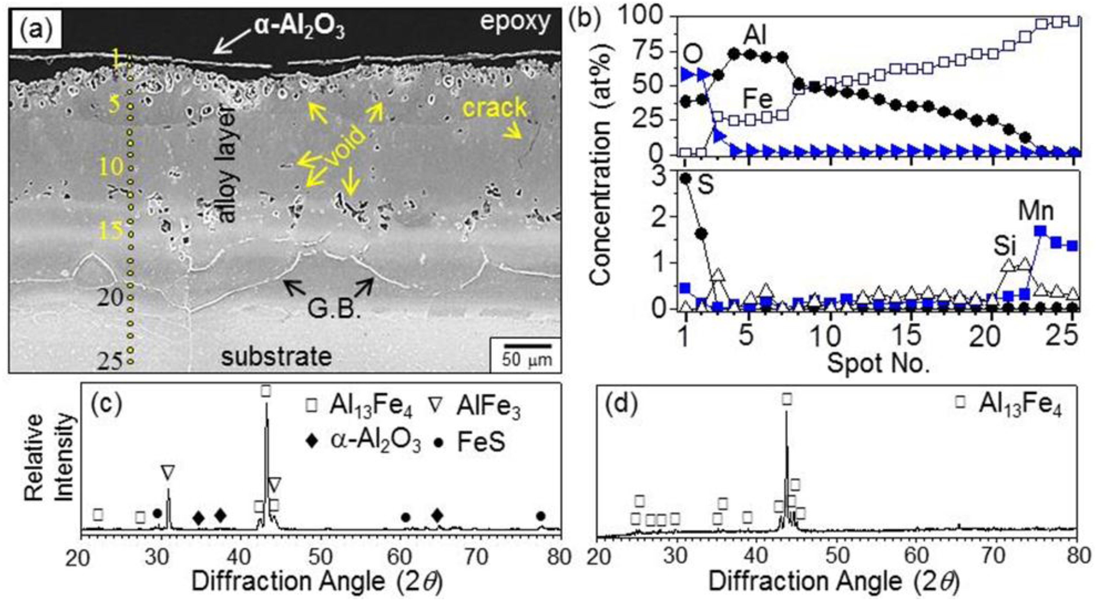
Figure 4 shows SEM/EDS/XRD results of the Al hot-dipped carbon steel after corrosion at 800 °C for 100 h. In Figure 4a, the α-Al2O3 scale was about 5 µm thick, non-adherent, and partially broken owing to the excessive stress accumulated in the scale as well as the hydrogen and sulfur released from the H2S gas. According to the SEM-EDS analysis, the composition of spot 1 shown in Figure 4b was 38.9% Al-58.1% O-2.8% S-0.2% Fe in wt. %, which indicated that α-Al2O3 was incorporated with some sulfur and iron. Such was also observed at the spot 2 shown in Figure 4b. Sulfur and iron ions that were doped in the highly stoichiometric α-Al2O3 may constitute additional energy levels localized in the forbidden energy band, which would beneficially increase the defect mobility in α-Al2O3 and thereby enhance the formation of α-Al2O3. Sulfur was present only at spot 1 (2.8 wt. %) and spot 2 (1.6 wt. %). However, oxygen was present all over spots 1–25, with its concentration (wt. %) gradually decreased from 58.1% O at spot 1 to 0.6% O at spot 25. This suggested that oxygen diffused inwardly faster and more in-depth than sulfur. Nevertheless, the thin α-Al2O3 scale effectively protected the steel, suppressing the formation of the non-protective FeS or less protective Al2S3 scale at the coating surface. In Figure 4a, spots 1–15 were not able to be etched due to the dissolution of oxygen and sulfur to a certain amount, while spots 15–25 were able to be etched, which revealed coarse, fully grown substrate grains. Hence, the boundary between the retained coating and the substrate may be designated as spot 15. Numerous voids formed at spots 12–16, and furthermore, at spots 2–4 due to the interdiffusion between the coating and the substrate. The amount of void formation increased with an increase in the corrosion temperature and time. A few cracks formed due to thermal expansion mismatch between coating and the steel substrate [6]. Because of the counter-diffusion of Al and Fe, the characteristic finger- or tongue-like morphology as shown in Figure 1a was no longer observable in Figure 4a. In Figure 4c, the strongest peaks were in the order of Al13Fe4 and AlFe3, indicating that the upper part of the retained coating (viz around spot 3 in Figure 4a) consisted of Al13Fe4 as the major phase and AlFe3 as the minor phase. Additionally, faint peaks of α-Al2O3 and FeS were detected in Figure 4c. A small amount of FeS was formed at the coating surface not only because of the α-Al2O3 scale spallation but also due to the preferential oxidation of Al at the outer surface. When the upper part of the coating was ground off to reveal the underlying phases, Al13Fe4 became the major phase (Figure 4d). The EDS concentration profile also corresponded to the Al13Fe4 phase around the ground off area (viz spots 19 and 20). The alloying elements such as Mn and Si tended to be present more around spots 21–25, apparently owing to the inward transportation of Al that expelled Mn and Si.
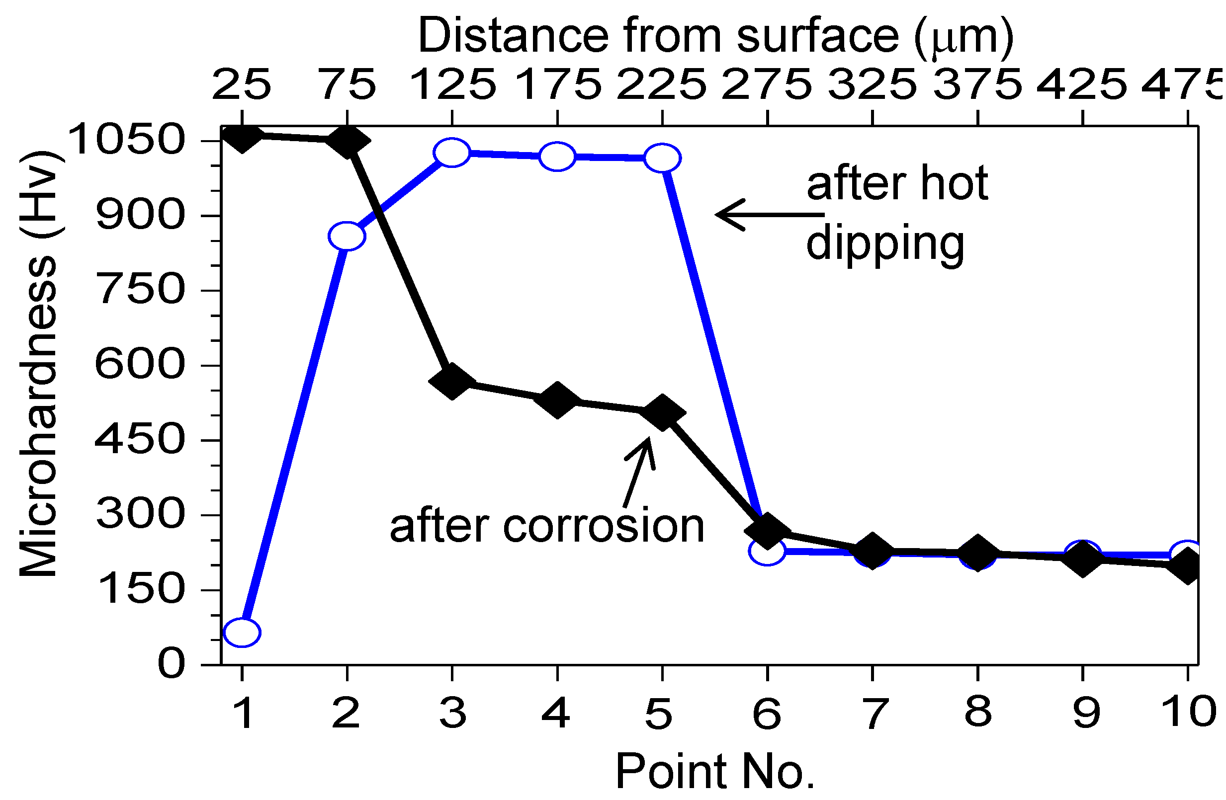
Figure 5 shows the microhardness profile of the Al hot-dipped carbon steel. Before heating, the microhardness (Hv) was about 65 for point 1 (viz Al topcoat), 859 for point 2 (viz Al3Fe), 1020 for points 3–5 (viz Al5Fe2 in the alloy layer), and 223 for points 6–10 (viz α-Fe substrate). Such hardness increment due to hot-dipping can improve the wear resistance and beneficially enhance the service life of the steel [6]. After heating at 800 °C for 100 h, the microhardness of points 1 and 2 increased mainly due to oxidation or the incorporation of oxygen in the coating, whereas that of points 3–6 decreased mainly due to the counter-diffusion of Al and Fe, which changed the brittle Al5Fe2-rich alloy layer to the ductile (AlFe or Al13Fe4)-rich alloy layer or another ductile Al-dissolved layer. Ductile AlFe and Al13Fe4 may be used as structural components because of their good oxidation- and corrosion-resistance, and high specific strength [5]. The microhardness of the substrate did not change noticeably before and after heating.
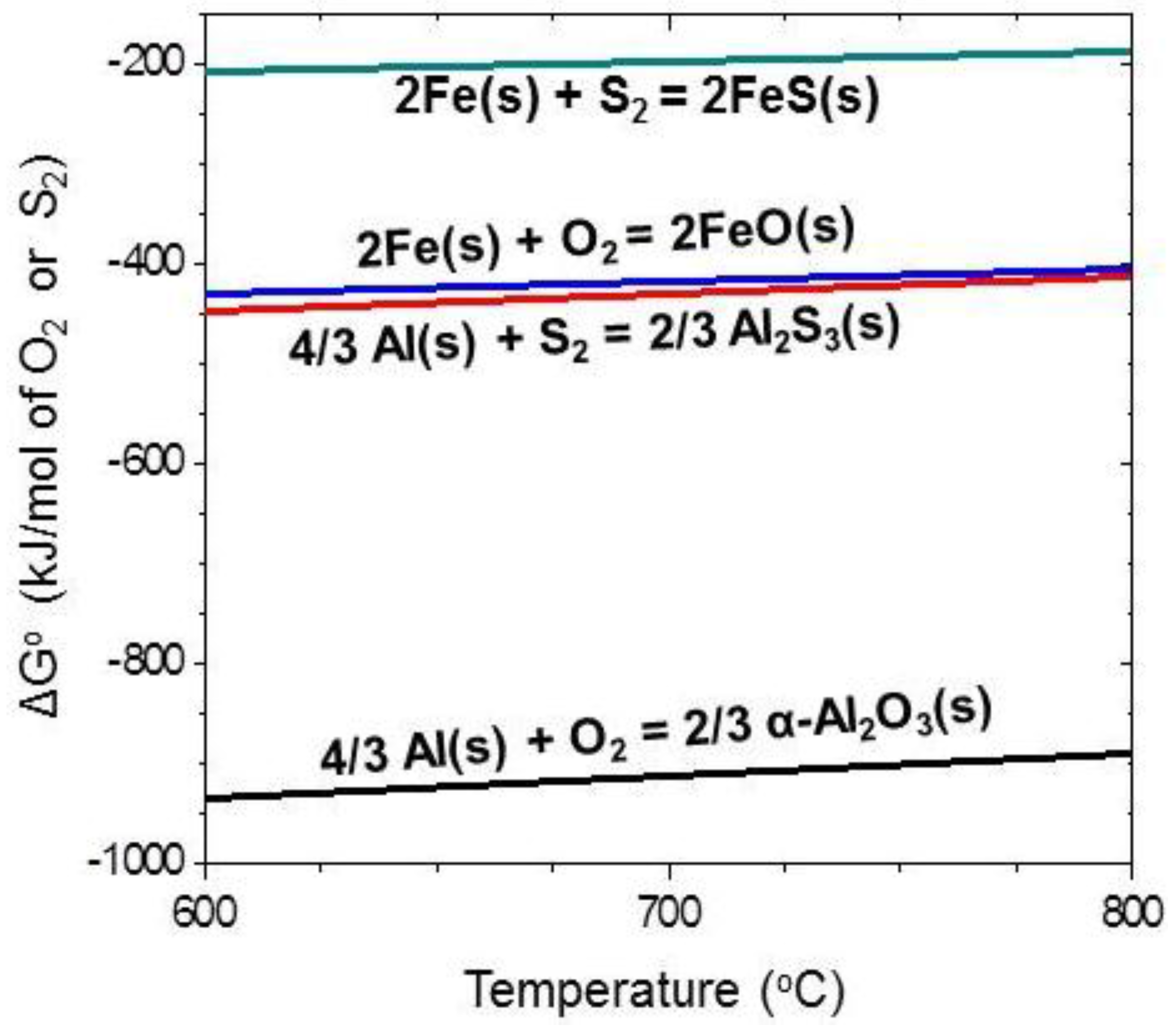
Figure 6 shows the Ellingham diagram (data from [10]). The oxides were more stable than the corresponding sulfides, whereas Al was more active than Fe. Hence, the most stable α-Al2O3 formed preferentially upon exposure of the Al hot-dipped steel to N2/0.1% H2S mixed gas, and suppressed the corrosion significantly. By contrast, the uncoated steel degraded rapidly not by oxidation but by sulfidation. Upon exposure of the uncoated steel to N2/0.1% H2S mixed gas, FeO and FeS would form competitively. Since FeS is much more non-stoichiometric than FeO, FeS overgrows FeO and covers the whole surface as the corrosion proceeds. The fast growth rate of FeS, incorporation of hydrogen and sulfur, void formation, and excessive stress that generated owing to the compositional difference in the scale resulted in the cracking and detachment of the FeS scale, allowing the direct contact of N2/0.1% H2S gas with the uncoated steel. This further accelerated the corrosion of the uncoated steel.

4. Conclusions

The carbon steel was hot-dipped in a molten Al bath, and corroded in N2/0.1% H2S mixed gas at 600–800 °C for up to 100 h. The Al hot-dipping was found to be a good surface modification technique for the employed steel. The coating consisted primarily of the Al topcoat and an Al-Fe alloy layer firmly adhered on the steel substrate. The Al topcoat partially oxidized to the thin and non-adherent α-Al2O3 scale from the surface. This effectively protected the carbon steel substrate. The formation of the α-Al2O3 layer was highly preferred, because alumina grows quite slowly due to its high stoichiometry. Heating during the corrosion accompanied the counter-diffusion of Al and Fe. This made the finger- or tongue-like morphology at the (Al-Fe alloy layer)/steel interface diffuse and dull, converted the Al-Fe intermetallic phases, changed the microhardness, and formed Kirkendall voids and cracks in the coating. In the case of uncoated carbon steel, thick, fragile, non-adherent FeS scales formed on the surface because hydrogen dissolved in the scales and non-protective sulfide scales formed.

Acknowledgments

This work was supported by the Korea Institute of Energy Technology Evaluation and Planning (KETEP) grant (No. 20143030050070) funded by the Korea government Ministry of Trade, Industry and Energy.

Author Contributions

Muhammad Ali Abro performed the experimental work, and drafted the paper. Dong Bok Lee supervised the experimental work, microstructural analyses, and finalized the paper.

Conflicts of Interest

The authors declare no conflict of interest.

References

  1. Mrowec, S.; Przybylski, K. Transport properties of sulfide scales and sulfidation of metals and alloys. Oxid. Met. 1985, 23, 107–139. [Google Scholar] [CrossRef]
  2. Richards, R.; Jones, R.; Clements, P.; Clarke, H. Metallurgy of continuous hot dip aluminizing. Int. Mater. Rev. 1994, 39, 191–212. [Google Scholar] [CrossRef]
  3. Bouayad, A.; Gerometta, C.; Belkebir, A.; Ambari, A. Kinetic interactions between solid iron and molten aluminium. Mater. Sci. Eng. A 2003, 363, 53–61. [Google Scholar] [CrossRef]
  4. Deqing, W.; Ziyuan, S. Formation of Al2O3 layer on steel. J. Mater. Sci. Lett. 2003, 22, 1003–1006. [Google Scholar] [CrossRef]
  5. Kobayashi, S.; Yakou, T. Control of intermetallic compound layers at interface between steel and aluminum by diffusion-treatment. Mater. Sci. Eng. A 2002, 338, 44–53. [Google Scholar] [CrossRef]
  6. Van Trung, T.; Kim, M.J.; Bong, S.J. Characterization of microstructure, hardness and oxidation behavior of carbon steels hot dipped in Al and Al-1 at. % Si molten baths. Korean J. Met. Mater. 2012, 50, 575–582. [Google Scholar]
  7. Cheng, W.-J.; Wang, C.-J. Study of microstructure and phase evolution of hot-dipped aluminide mild steel during high-temperature diffusion using electron backscatter diffraction. Appl. Surf. Sci. 2011, 257, 4663–4668. [Google Scholar] [CrossRef]
  8. Cheng, W.-J.; Wang, C.-J. Microstructural evolution of intermetallic layer in hot-dipped aluminide mild steel with silicon addition. Surf. Coat. Technol. 2011, 205, 4726–4731. [Google Scholar] [CrossRef]
  9. Bouche, K.; Barbier, F.; Coulet, A. Intermetallic compound layer growth between solid iron and molten aluminium. Mater. Sci. Eng. A 1998, 249, 167–175. [Google Scholar] [CrossRef]
  10. Barin, I. Thermochemical Data of Pure Substances; Wiley-VCH: Weihheim, Germany, 1989. [Google Scholar]
Figure 1. Al hot-dipped carbon steel: (a) Etched cross-sectional OM image; (b) EDS concentration profiles along the spots 1–22 marked in Figure 1a; (c) XRD pattern taken from the air-side; (d) XRD pattern after grinding off the Al topcoat.
Metals 06 00038 g001
Figure 2. Al hot-dipped carbon steel after corrosion at 600 °C for 50 h in N2/0.1% H2S gas: (a) XRD pattern; (b) etched cross-sectional OM image.
Metals 06 00038 g002
Figure 3. Uncoated steel after corrosion in N2/0.1% H2S at 600 °C for 50 h: (a) SEM cross-sectional image; (b) XRD pattern.
Metals 06 00038 g003
Figure 4. Al-hot dipped steel after corrosion in N2/0.1% H2S at 800 °C for 100 h: (a) etched cross-sectional SEM image; (b) concentration profiles of Al, Fe, Mn, Si, S and O; (c) XRD pattern taken from the air-side; (d) XRD pattern after grinding off the upper part of the coating.
Metals 06 00038 g004
Figure 5. Microhardness variation along the depth of the Al hot-dipped carbon steel before and after heating at 800 °C for 100 h in N2/0.1% H2S gas.
Metals 06 00038 g005
Figure 6. Ellingham diagram of oxides and sulfides that can form on the Al hot-dipped steel.
Metals 06 00038 g006

