Article

Microstructure, Mechanical and Corrosion Properties of Friction Stir Welding High Nitrogen Martensitic Stainless Steel 30Cr15Mo1N

1
School of Metallurgy, Northeastern University, Shenyang 110819, China
2
Guangdong Welding Institute (China-Ukraine E. O. Paton Institute of Welding), Guangzhou 510650, China
*
Author to whom correspondence should be addressed.
Metals 2016, 6(12), 301; https://doi.org/10.3390/met6120301
Submission received: 29 October 2016 / Revised: 19 November 2016 / Accepted: 28 November 2016 / Published: 30 November 2016

Abstract

:
High nitrogen martensitic stainless steel 30Cr15Mo1N plates were successfully welded by friction stir welding (FSW) at a tool rotation speed of 300 rpm with a welding speed of 100 mm/min, using W-Re tool. The sound joint with no significant nitrogen loss was successfully produced. Microstructure, mechanical and corrosion properties of an FSW joint were investigated. The results suggest that the grain size of the stir zone (SZ) is larger than the base metal (BM) and is much larger the case in SZ-top. Some carbides and nitrides rich in chromium were found in BM while not observed in SZ. The martensitic phase in SZ could transform to austenite phase during the FSW process and the higher peak temperature, the greater degree of transformation. The hardness of SZ is significantly lower than that of the BM. An abrupt change of hardness defined as hard zone (HZ) was found in the thermo-mechanically affected zone (TMAZ) on the advancing side (AS), and the HZ is attributed to a combination result of temperature, deformation, and material flow behavior. The corrosion resistance of SZ is superior to that of BM, which can be attributed to less precipitation and lower angle boundaries (LABs). The corrosion resistance of SZ-bottom is slight higher than that of SZ-top because of the finer grained structure.

1. Introduction

High nitrogen martensitic stainless steel is one of the superior materials that utilize nitrogen as an alternative alloying element instead of nickel [1,2]. Nitrogen additive in martensitic stainless steel could increase the austenite phase range and restrain the formation of δ-ferrite, maintain the substitutional solid-solution strengthening, as well as refine the carbide, which significantly enhance the strength, hardness and corrosion resistance of martensitic stainless steel [3,4,5]. Additionally, given the lack of nickel resources, high nitrogen martensitic stainless steel can be considered as one of the promising next generation martensitic stainless steels. However, in the case of the welding of martensitic stainless steel with high nitrogen content, conventional fusion welding processes remain some common problems, such as nitride desorption, formation of nitrogen associated pore, solidification cracks in stir zone (SZ) and nitride precipitation in the heat affected zone (HAZ) because of high heat-input [6,7,8]. These weld defects can deteriorate the mechanical properties and corrosion resistance of the joints. Thus, to avoid these drawbacks, exploring a reasonable welding technology for high nitrogen martensitic stainless steel was necessary [9,10].
Friction stir welding (FSW)—an innovative solid-state welding technology developed by TWI in 1991 [11]—is considered an effective technique, and has been widely used and investigated for low melting materials, such as Al and Cu alloys [12,13]. Recently, the application of FSW to higher melting materials including stainless steels [14,15,16] and carbon steels [17,18] has achieved significant progress with the development of welding tools. As a solid-state welding technology, FSW exhibits lower heat-input, which is benefit to suppress the formation of above weld defects.
So far, the exploration of FSW nitrogen-containing martensitic stainless steel is still limited. Chung et al. [19] investigated the peak temperature of FSW high carbon martensitic steel and discovered that the joint without phase transformation can be obtained when FSW is performed under appropriate conditions. Ueji et al. [20] examined the FSW JIS-SM490 steel with an untempered martensitic microstructure at a variety of tool rotation speeds. The results indicated that the hardness in SZ reduced significantly and the final grain size in SZ became coarser than that in the ultrafine starting microstructure. Furthermore, there is very little information reported on FSW martensitic stainless steel with high nitrogen content (such as 30Cr15Mo1N containing 0.38 wt. % nitrogen).
The primary purpose of this paper is an attempt to evaluate the feasibility of FSW high nitrogen martensitic stainless steel 30Cr15Mo1N. The microstructure of joint was revealed by optical digital microscope (ODM), scanning electron microscopy with energy-dispersive spectroscopy (SEM-EDS), transmission electron spectroscopy (TEM), X-ray diffraction (XRD) and electron backscatter diffraction (EBSD). The hardness and corrosion properties were performed using micro-hardness tester and electrochemical measurements.

2. Materials and Methods

The high nitrogen martensitic stainless steel 30Cr15Mo1N was prepared by pressurized induction furnace. Its chemical composition is listed in Table 1. The ingot was hot-forged and hot-rolled within 1050–1150 °C into a 4.3 mm thick plate. The plates were subsequently experienced a series of heat treatments, including normalizing at 985 °C for 1 h, annealing at 875 °C for 3 h, oil quenching at 1000 °C for 40 min, deep cryogenic treatment twice at −80 °C for 2 h and tempering twice at 450 °C for 2 h. Prior to welding, the plate with dimension of 200 mm × 130 mm × 4.3 mm was sectioned in half along the rolling direction.
The experimental plates were butt-welded in the direction parallel to the rolling direction at a rotation rate of 300 rpm and a traveling rate of 100 mm/min with a W-Re tool that possessed a shoulder diameter of 20 mm, probe diameters of 4.5–8 mm (tapered pin) and a probe length of 4.2 mm. The tool was tilted by 0° and the downward force was kept at 20 kN. An argon shielding gas at the flow rate of 21 L/min was maintained to minimize surface oxidation.
In order to evaluate nitrogen desorption, the nitrogen contents of BM and SZ were analyzed by LECO TC 500 (LECO, Saint Joseph, MI, USA). The metallographic structure was revealed on the cross-section of the FSW joint using optical microscope (OM, Olympus Corporation, Tokyo, Japan), scanning electron microscope (SEM, Carl-Zeiss, Oberkochen, Germany) and transmission electron microscope (TEM, FEI, Hillsboro, OR, USA). Specimens for OM and SEM were etched using 0.4 g of K2SO3 dissolved in 10 mL concentrated hydrochloric acid and 50 mL distilled water for 15 s. In terms of electron back-scattered diffraction (EBSD) observation, vibratory polishing for 8 h was needed to remove the stress layer on specimen surface. The phase composition in the weld and BM was analyzed using X-ray diffraction (XRD, Bruker, Berlin, Germany).
In addition, micro-hardness was performed traversing the joint interface both horizontally and longitudinally. The hardness profiles were scanned on the centerlines of the cross-section of the weldment with regular intervals of 0.5 mm under a load of 200 gf for 10 s dwell time across.
Samples for corrosion tests were firstly subjected to passivation treatment in 20–30 wt. % nitric acid solution at 50 °C for 1 h, subsequently mounted in epoxy resin, and then mechanically ground to a 2000 grit finish with SiC paper. A typical three-electrode system, consisting of working electrode, a platinum foil (Pt) as the counter electrode and a saturated calomel electrode (SCE) as the reference electrode, was employed for all the electrochemical measurements. The potentiodynamic polarization and electrochemical impedance spectroscopy (EIS) were both carried out in 3.5 wt. % NaCl solution at 25 °C ± 0.5 °C using the Gamry Reference 600 potentiostats (Gamry, Warminster, PA, USA). The potentiodynamic polarization was swept at a rate of 0.333 mV/s from −0.3 V/OCP to the anodic direction, and finished when the current density exceeded 0.1 mA/cm2. The EIS experiments were performed with 10 mV amplitude perturbation in the frequency ranging from 100 kHz to 10 mHz. The experimental results were analyzed using the equivalent circuit embedded in Echem Analyst software (Gamry, Warminster, PA, USA).

3. Results and Discussion

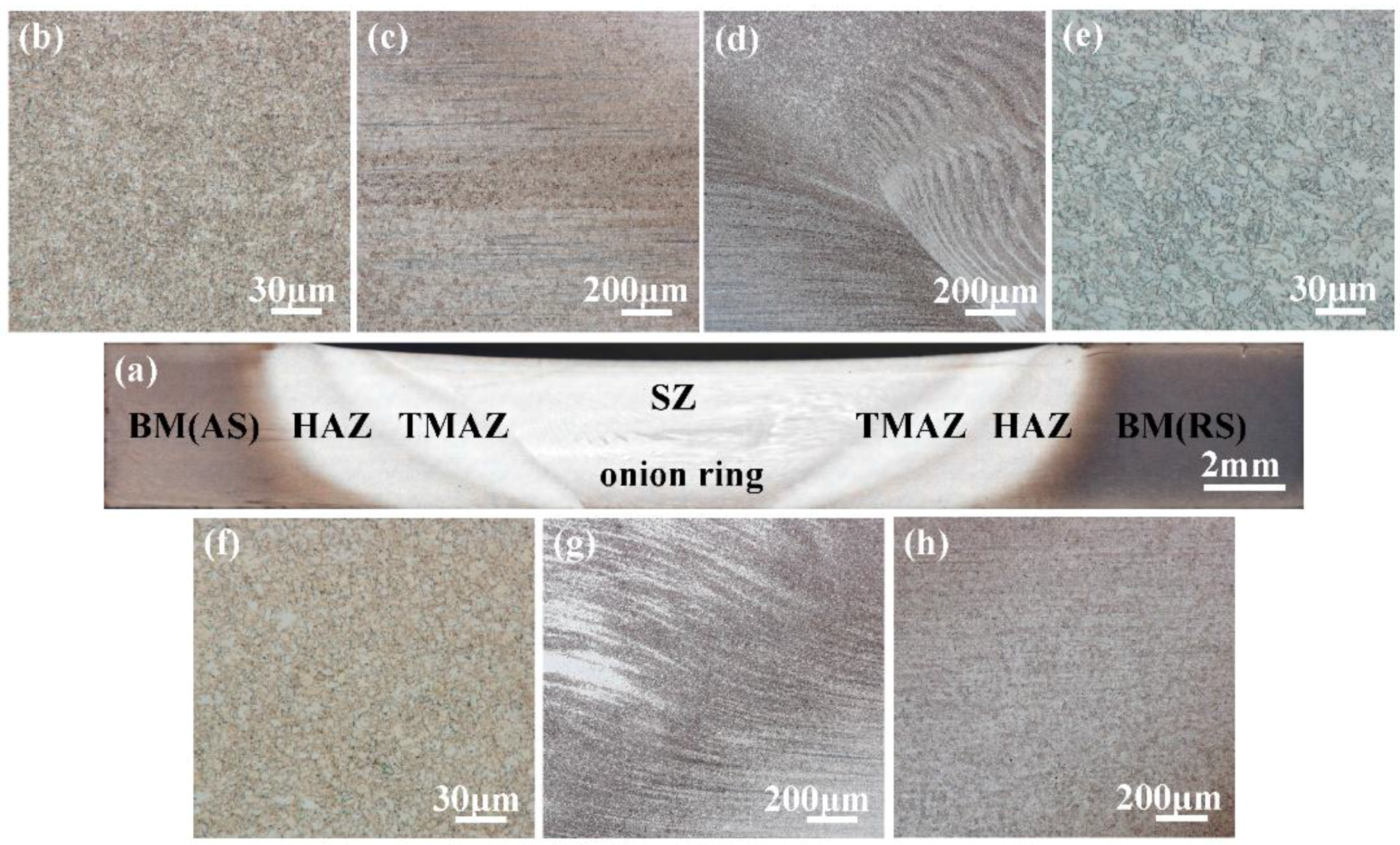
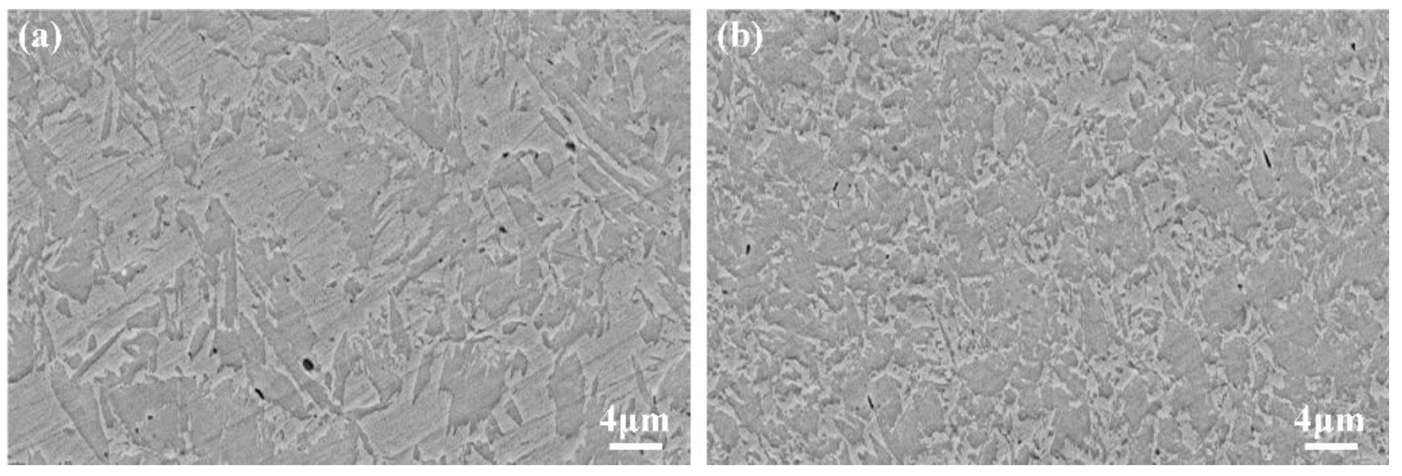
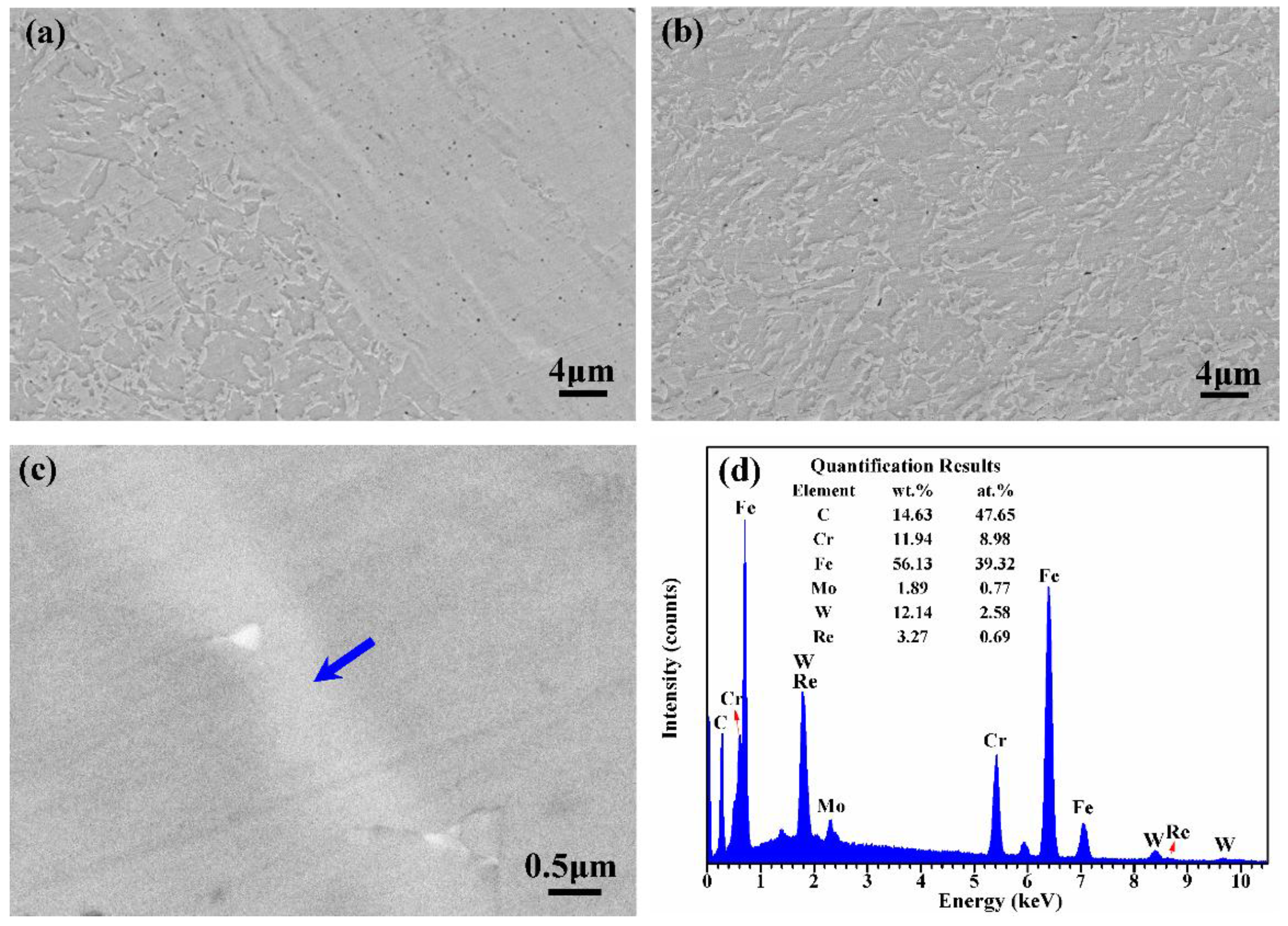
3.1. Macro- and Microstructure Observation

The close up view of the top surface of the FSW joint is shown in Figure 1. It is observed that the SZ surface is characterized by the presence of a smooth, closely spaced ripple formation. Under the above welding parameters, the sample was perfectly welded without any surface-breaking defects like pores, groove-like defects and surface galling, which implies that the heat-input was sufficient to maintain the material flow during FSW process [21].
The nitrogen contents of BM and SZ were 0.3806 and 0.3604 wt. % respectively, which indicated that only a little leak of nitrogen happened in SZ during FSW process. From the cross-section view of the FSW joint (Figure 2a), it was clearly observed that no nitrogen blowhole, which often formed in traditional fusion welding methods, was found in the joint [7]. Therefore, it can be concluded that the FSW is an effective welding method for this steel to prevent nitrogen desorption.
The macrostructure of the weld, characterized by a “basin-shape” and no internal defects, is displayed in Figure 2a, which can be divided into several regions distinctly, such as base metal (BM), stir zone (SZ), heat-affected zone (HAZ), and thermo-mechanically affected zone (TMAZ). Apart from that, depending on the rotational direction of the tool, the left- and right-hand sides of the as-welded joint are termed as the advancing side (AS) and retreating side (RS), respectively. Particularly, an “onion ring”, also described in other researches [22,23,24], can be observed in the middle of SZ, which indicates the phenomenon of material flow and plastic deformation happening during the FSW process [24,25]. The formation of this “onion ring” was thought to correspond to the geometry principle of the extrusion of cylindrical sheets of material caused by each rotation of the tool [26].
Optical micrographs of BM and different regions of FSW joint are displayed in Figure 2b–h. According to Figure 2e,f, it could be seen that the grain size in SZ-top is larger than that in SZ-bottom. This phenomenon can be attributed to two causes. Firstly, it was believed that maximum temperature occurs at the top surface of the welded joint where the friction dominating heat generation happens between tool shoulder and workpieces [25]. Secondly, owing to the direct touch between the bottom surface of weldment and the backing plate, comparing to the top part of SZ, the bottom one possesses a higher thermal conductivity and lower peak temperature [27]. These two factors effectively retard the grain growth and contribute to smaller grains in SZ-bottom. As a result of the specific metal flow and stress distribution, a band structure with lamellar and streamline structure can be observed at the region surrounding the boundary of TMAZ/SZ-AS (Figure 2d). Some other studies also found this phenomenon [28,29,30,31]. Additionally, the interface between SZ and TMAZ on the AS (Figure 2d) is relatively sharper than that on the RS (Figure 2g), which was associated with the difference of shear stress between the tool and the material on different sides [32]. The microstructure of HAZ on the AS (Figure 2c) presents a slightly distinct band structure, while it is more diffuse on the RS (Figure 2h).
Figure 3 illustrates the SEM micrograph of BM and its corresponding EDS analysis. From Figure 3a, the microstructure of BM is dominated by lath martensitic with some granular precipitates. From the magnified SEM image of BM (Figure 3b) and the result of its EDS analysis (Figure 3c), it can be indicated that the precipitates are mainly carbides and nitrides rich in chromium. It can be deduced that a Cr depletion zone could be exist in the vicinity of the precipitates [33].
From Figure 4, in addition to the above-mentioned difference of grain size between the SZ-top and SZ-bottom, the phase composition and proportions of these two areas appear to be different, which is related to the temperature history of SZ during FSW process. Furthermore, comparing with BM, less precipitates are found in SZ, irrespective of top or bottom, which is associated with exposure to high temperature and cutting by deformation in the process of FSW. Similarly, many other researchers [34,35,36] also observed this phenomenon during FSW. In view of the above observation, therefore, a detailed study on weld temperature history is very crucial.
During friction stir welding process, the intense plastic deformation around the rotation pin and severe friction between shoulder and the weld plates are two main factors resulting in the temperature rise within the SZ and its vicinity [25]. It is readily predictable that an austenite transformation will occur when the peak temperature exceeds Ac1. Arbegast and Hartley [37] demonstrated that a general relationship between peak temperature (T, °C) and FSW parameters (ω, ν) can be explained as:
T = K   ( ω 2 ν × 10 4 ) α   T m
where T is the peak temperature during welding (°C), Tm is the melting point of the alloy (°C), ω is the tool rotation speed, ν is the tool traversing speed, and the exponent α and the coefficient K are about 0.005 and 0.7 (based on the research of FSW martensitic steel by Ghosh et al. [38]), respectively. According to the Equation (1), the peak temperature T in this study was approximately 1004 °C, which is much higher than the Ac1 (870 °C) of BM. Therefore, it can be deduced that the initial martensitic microstructure transformed to austenite during FSW process. Similar results were reported by Ghosh et al. [38] and Nandan et al. [24]. In addition, owing to the higher peak temperature, the degree of phase transformation at SZ-top was very thorough. Similar results reflecting the martensitic fraction variation from top to bottom of FSW joint have been reported earlier in the case of hyper-eutectoid steel [19].
Figure 5a,b shows the SEM micrographs of TMAZ/SZ-AS and TMAZ/SZ-RS, respectively. It is clearly seen that there is a distinct boundary on the TMAZ/SZ-AS, while no obvious border on TMAZ/SZ-RS. Moreover, some white bands can also be found in the vicinity of the boundary on TMAZ/SZ-AS (as indicated by the arrow in Figure 5c). Figure 5c illustrates the magnified image of Figure 5a in back-scattered pattern. The EDS analysis demonstrates that these bands contain W and Re elements (Figure 5d), which formed by the tool wear owing to high friction load between weldments and tool. A related study has been conducted by Prado et al. in the case of the tool wear behavior in FSW 6061Al-20% Al2O3 composite [39].
According to the microstructures of TEM bright- and dark-field images in SZ (Figure 6a,b), some austenite can be clearly observed, which is the typical evidence of transformation from martensitic to austenite during FSW process. This agrees well with the above-discussed statement about the temperature history. Furthermore, in all four TEM images, no apparent precipitates can be seen in SZ, which is consistent with the observation results of SEM. TEM micrographs of two typical regions located at SZ are exhibited in Figure 6c,d. These images illustrate the two regions owning low density of dislocations and high density of dislocations, respectively, while the former pattern dominated the most part of the microstructure of the specimens. The reason for this is presented as follow. FSW process gives rise to not only intense plastic flow in SZ, but also subsequently many dislocations and the subgrains [40]. Whereas, for another, the temperature history generated by plastic deformation induces the occurrence of recovery partially removing dislocations and stimulating the growth of grain [41,42]. Consequently, in this study, the balancing result of deformation and recovery is most of SZ governed by a low-density dislocation network structure. Sato et al. [43] also found this similar phenomenon in the case of FSW 1080Al-O.

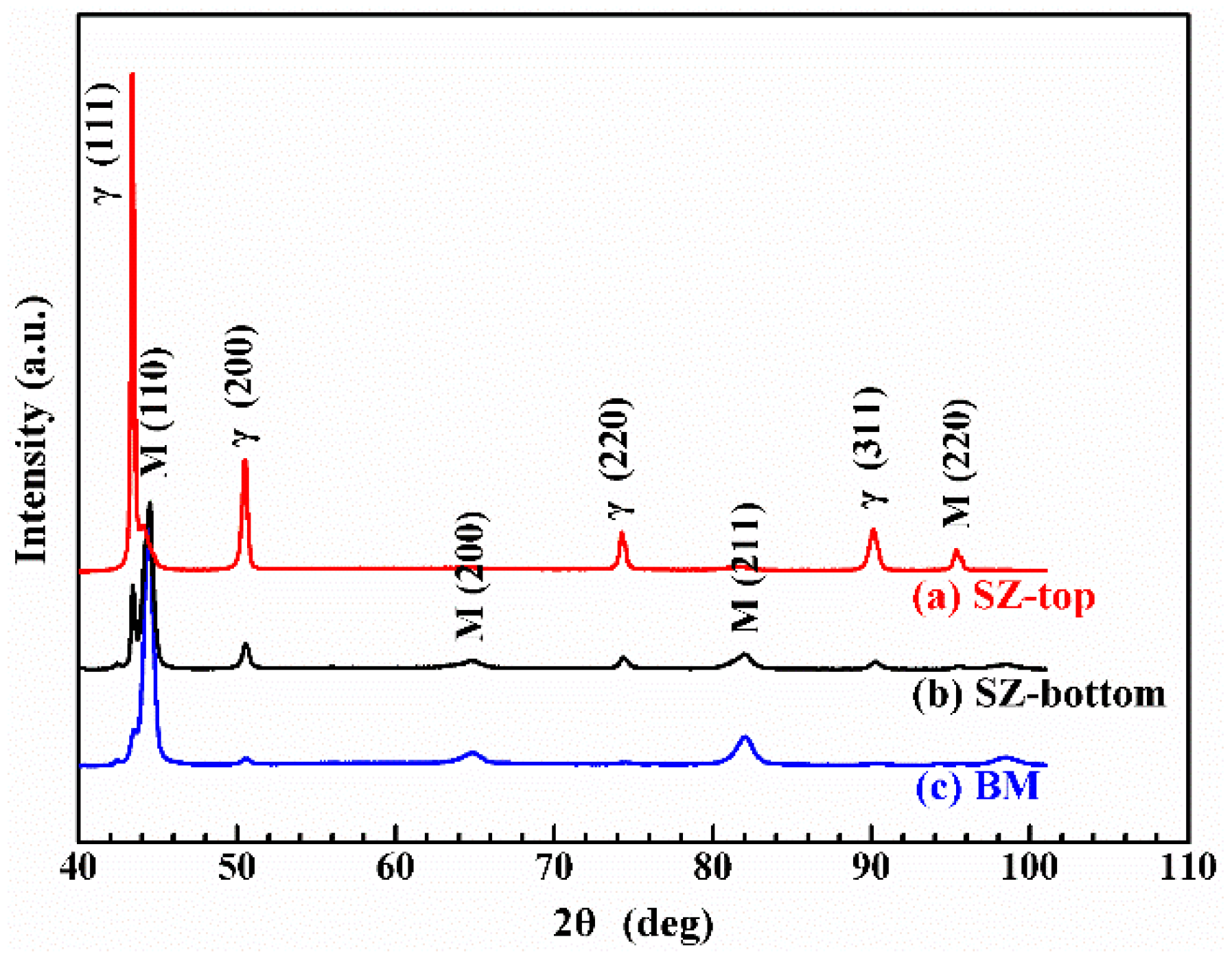
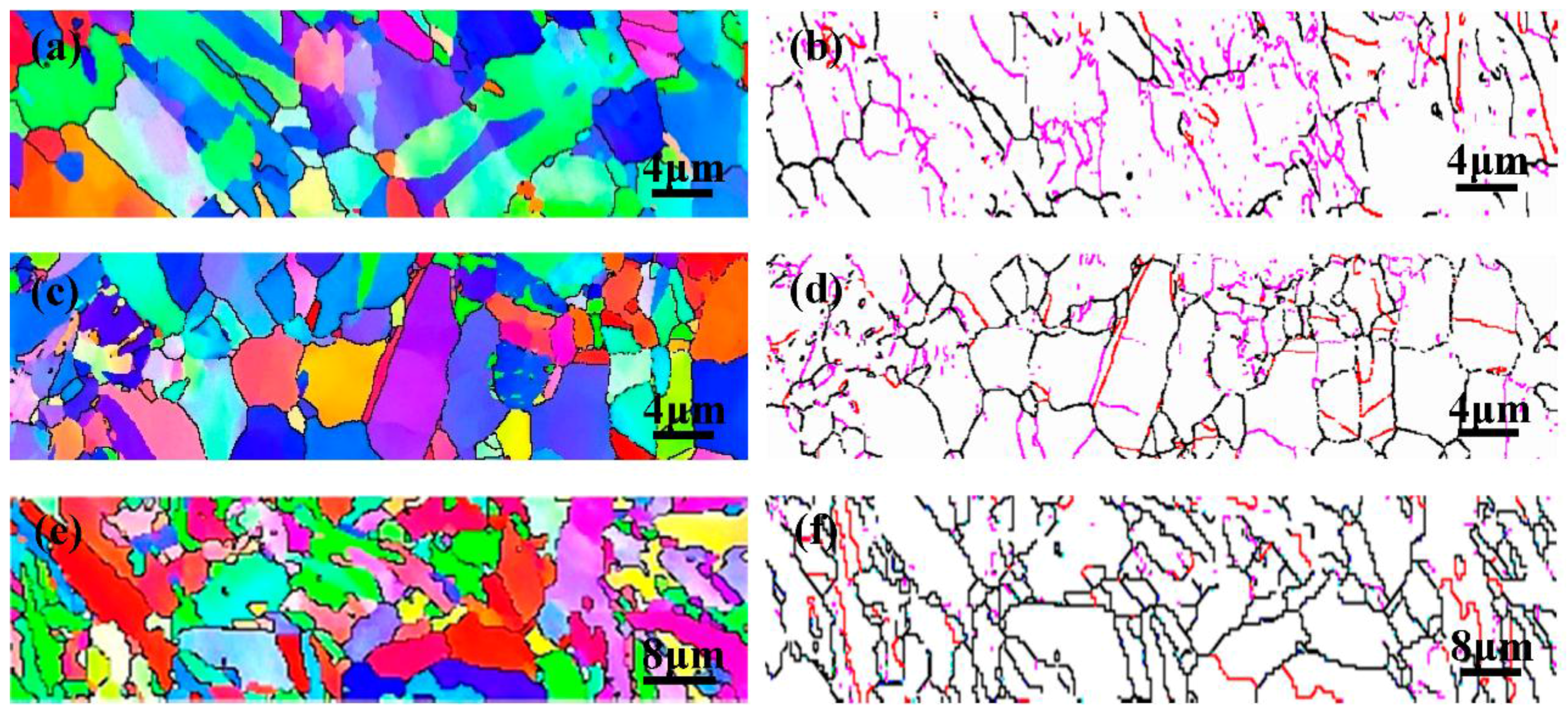
3.2. X-ray Diffraction and EBSD Test

Figure 7 shows the X-ray diffraction pattern for SZ-top, SZ-bottom and BM of FSW weldment. It is obvious that the peak intensities of different regions are quite different, indicating the occurrence of phase transformation in SZ during FSW process. In particular, the martensitic peak intensities undergo an upward trend whereas the austenite peak intensities experience a downward one in the order of SZ-top, SZ-bottom and BM, revealing that an incomplete austenitic transformation happened in the SZ-bottom due to the superior cooling condition and a relative low peak temperature. It is well consistent with the above discussion with regard to temperature history.
In order to clearly observe the grain size, shape, grain boundaries characteristics and the phase proportion of martensitic and austenite, an EBSD measurement was conducted at a higher magnification. The orientation maps in SZ-top, SZ-bottom and BM are shown in Figure 8a,c,e, respectively. It is obvious that the grain size in SZ-top is the biggest among these three, followed by SZ-bottom, and BM is the smallest, demonstrating that the grain in SZ experiences a significant growth during FSW process. Additionally, several elongated coarse grains were present in both SZ-top and SZ-bottom, resulting from fierce deformation and material flow along with tool rotation during FSW process.
Figure 8b,d,f shows the high angle boundaries (HABs) with misorientation angles higher than 15°, low angle boundaries (LABs) with misorientation angles between 2° and 15°, and Σ3 twin boundaries which are depicted as black, pink and red lines, respectively. It is shown that the BM has a grain structure containing many Σ3 twin boundaries, while regions both SZ-top and SZ-bottom exhibit a lower proportion of Σ3 twin boundaries, which can be ascribed to the intense deformation, associated with friction stir process breaks up the initial microstructure of BM [15]. Nevertheless, SZ-top and SZ-bottom display more LABs and fewer Σ3 boundaries, which is an evidence of experiencing intense deformation and dynamic recrystallization [15,44].
Figure 9 illustrates the EBSD phase distribution of different region of weldment. According to the results, BM contains fewer austenite phase, while after welding, more austenite phase generated in SZ and its proportion in SZ-top is higher than that in SZ-bottom. It further confirms the occurrence of austenization within SZ during FSW process, which is well consistent with the temperature history discussion and XRD results. Also, it is concluded that the proportion of austenite phase rises with the increment of peak temperature.

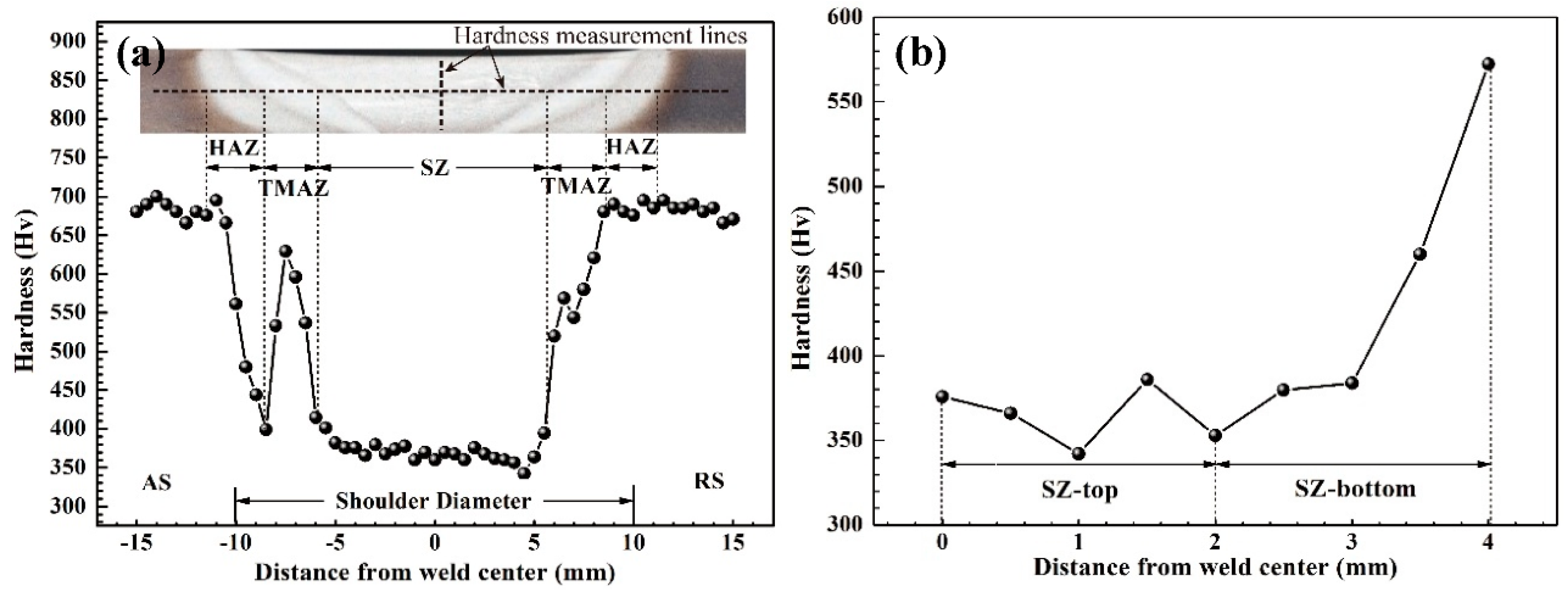
3.3. Micro-Hardness Distribution

The micro-hardness across the mid thickness of the welded joint was measured and presented in Figure 10a. The hardness of BM is approximately 690 Hv and the average hardness of SZ is about 371 Hv, ranging from 342 Hv to 415 Hv. The hardness in SZ on AS is exhibited a little bit higher than that on RS, which is associated with the pinning effect of the aggregate tool debris on the grain growth [20].
The profile characteristic of weldment hardness is depicted as follows. The hardness of SZ exhibits the minimum value and a sudden change takes place in TMAZ on AS where a peak value of 625 Hv exists halfway. In previous studies [45,46], the region of the abrupt change of hardness was defined as hard zone (HZ) and attributes this to a combination result of temperature, deformation, and material flow behavior. A common characteristic of HZ is the distinct band structure found in the TMAZ/SZ-AS and the hardening effect is attributed to local high flow stress. Sowards et al. [46] believed that high flow stress existing in the alternative banding structure lead to a sudden hardness rise. When it comes to HAZ, regardless of which side, the hardness value climbs considerably to that of the BM, which results from the elevated volume fraction of martensitic caused by thermal history.
Based on the microstructure evaluation discussed above, during FSW process, the SZ underwent an austenitic transformation. It is consensus that the martensitic is a harder phase relative to the austenite. Therefore, that is one of the reasons why the hardness in BM is much higher than that in SZ. Apart from that, the difference of grain size between BM and SZ is the main reason for the difference in hardness. According to the results of EBSD, the grain size in BM is much smaller than that in SZ. Obviously, under the as-received heat treatment process, an ultrafine grain was obtained in BM and the final grain size in SZ becomes coarser [24]. Ueji et al. [20] have been conducted research into the case of high carbon steel with untempered martensitic microstructure and have found the coarse effect in SZ after FSW. However, the effect of cutting of intense shear force during FSW, heat cycle, dissolution of precipitation and low dislocation density contribute to the phenomenon of grain-size coarse in SZ, which agrees well with the results of thermal history analysis, SEM and TEM, respectively. Therefore, it is believed that the overwhelming reason of softening in SZ is the grain coarse.
The profiles of vertical hardness scan along the tool axis direction though a depth of four millimeter is displayed in Figure 10b. Up to a three-millimeter depth from the weld surface, the hardness exhibits a relative stable tendency with an average value of approximately 370 Hv. However, a sharp increase occurs from three-millimeter to four-millimeter depth and the hardness continuously increases from 384 Hv to 572 Hv. According to the microstructure evaluation discussed above, during FSW process, an austenitic transformation occurred in SZ and the degree is verified on the basis of thermal distribution due to inhomogeneous cooling or heat flux within the weld [47]. Given the SZ-bottom with a higher cooling rate, a lower peak temperature was obtained and therefore a lower proportion of martensitic underwent phase transformation, resulting in a higher hardness relative to that of the SZ-top. Furthermore, elevated temperature accelerates the grain growth in SZ-top, which exerts a deleterious effect on hardness performance. Both two factors result in the sharp increase in hardness at SZ-bottom.

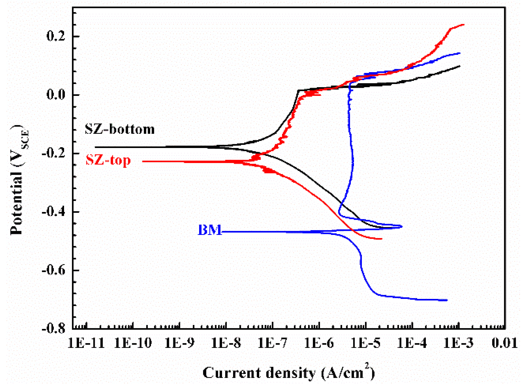
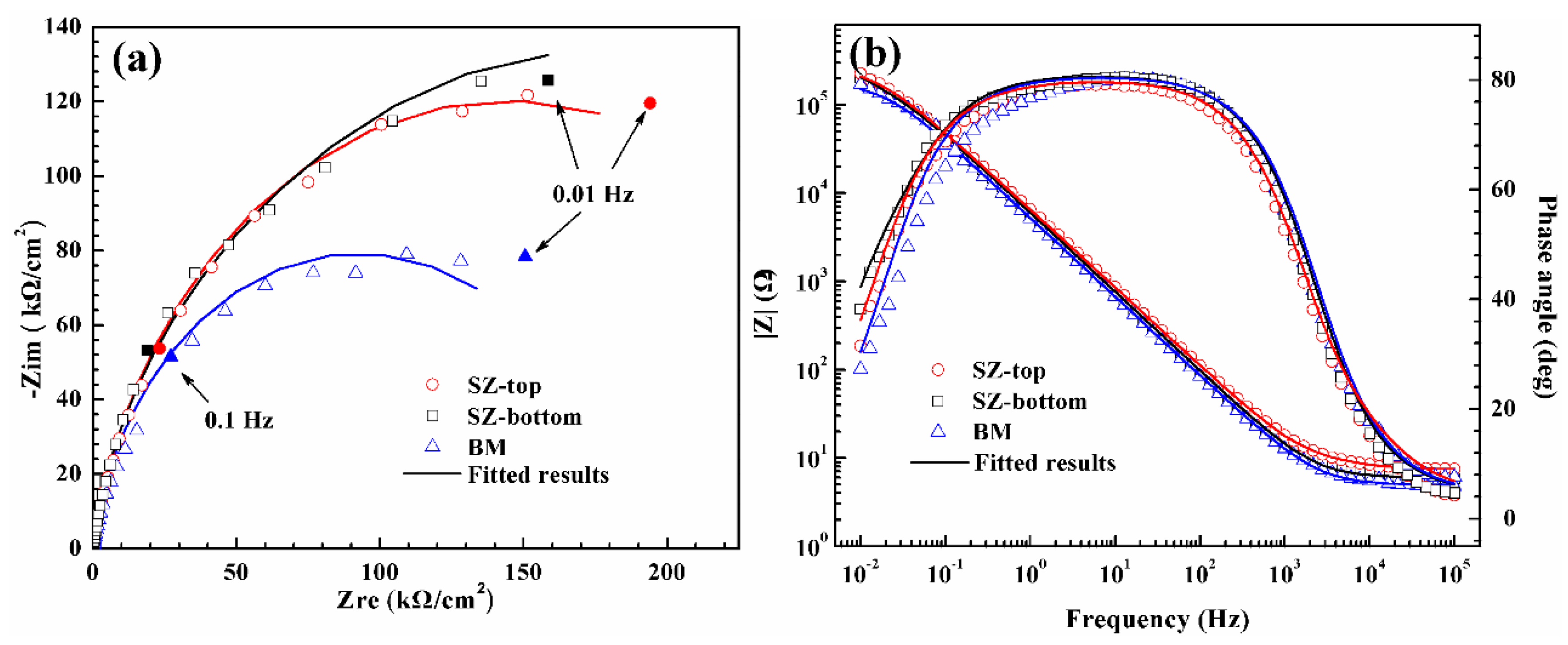
3.4. Corrosion Behavior

Figure 11 shows the potentiodynamic polarization curves of BM, SZ-top and SZ-bottom in 3.5 wt. % NaCl solution at 25 °C ± 0.5 °C. The pitting potentials of the three samples are similar. However, compared with the plot of BM, the cases of SZ-top and SZ-bottom possess higher corrosion potentials (Ecorr) and lower corrosion current densities (icorr). The result indicates that the corrosion resistance of SZ is superior to that of BM. In addition, the SZ-bottom sample has a slightly higher Ecorr and lower icorr than those of SZ-top, which implies a higher corrosion resistance of SZ-bottom. Similar conclusions can also be discovered in EIS measurements under the same experiment conditions, as shown in Figure 12. Nyquist plots (Figure 12a) exhibit a somewhat unfinished capacitive arc and the diameter of the semi-circular arc increased in the order of BM, SZ-top and SZ-bottom. Moreover, impedance modulus value at low frequency in Bode plots (Figure 12b) and the Rp value (Table 2) in equivalent circuit of specimens also increased in the same order. It further demonstrates that corrosion resistance of SZ was improved after FSW and that the case of SZ-bottom is the best.
In general, the corrosion resistance of the joint is affected by precipitation and grain boundary characteristics according to previous research [33,48,49]. On the one hand, little precipitation presents in SZ-top and SZ-bottom, while amounts of carbides and nitrides rich in chromium exist in BM, from the observation of SEM (Figure 4). The precipitation would result in the generation of Cr-depleted zone, which is sensitive to corrosion [33]. On the other hand, based on the results of EBSD (Figure 8), more LABs existed in SZ. Several investigations have clearly demonstrated that LABs could improve corrosion resistance [48,49]. Thus, the decrease of precipitation and the increase of LABs in SZ compared to the BM contribute to the improvement of corrosion resistance. Additionally, the grain size seems to be responsible for governing the extent of corrosion. The fine-grained structure, having high-density diffusion paths for alloy elements, is beneficial to Cr enrichment in the passive film [50,51]. Therefore, due to smaller grain size, SZ-bottom exhibits better corrosion resistance compared to that of SZ-top.

4. Conclusions

In the present study, the FSW of a high nitrogen martensitic stainless steel 30Cr15Mo1N plate was conducted at a rotation rate of 300 rpm and a traveling rate of 100 mm/min with a W-Re tool. Microstructural, mechanical and corrosion properties were investigated. The main conclusions can be summarized as follows:
(1)
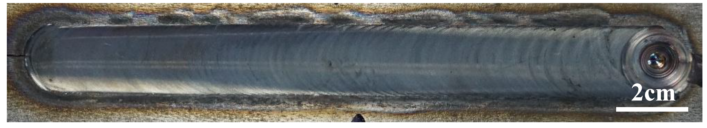
A sound FSW joint was successfully obtained without any defects. The SZ was characterized by coarse-grained microstructure, and no significant nitrogen loss occurred during FSW process.
(2)
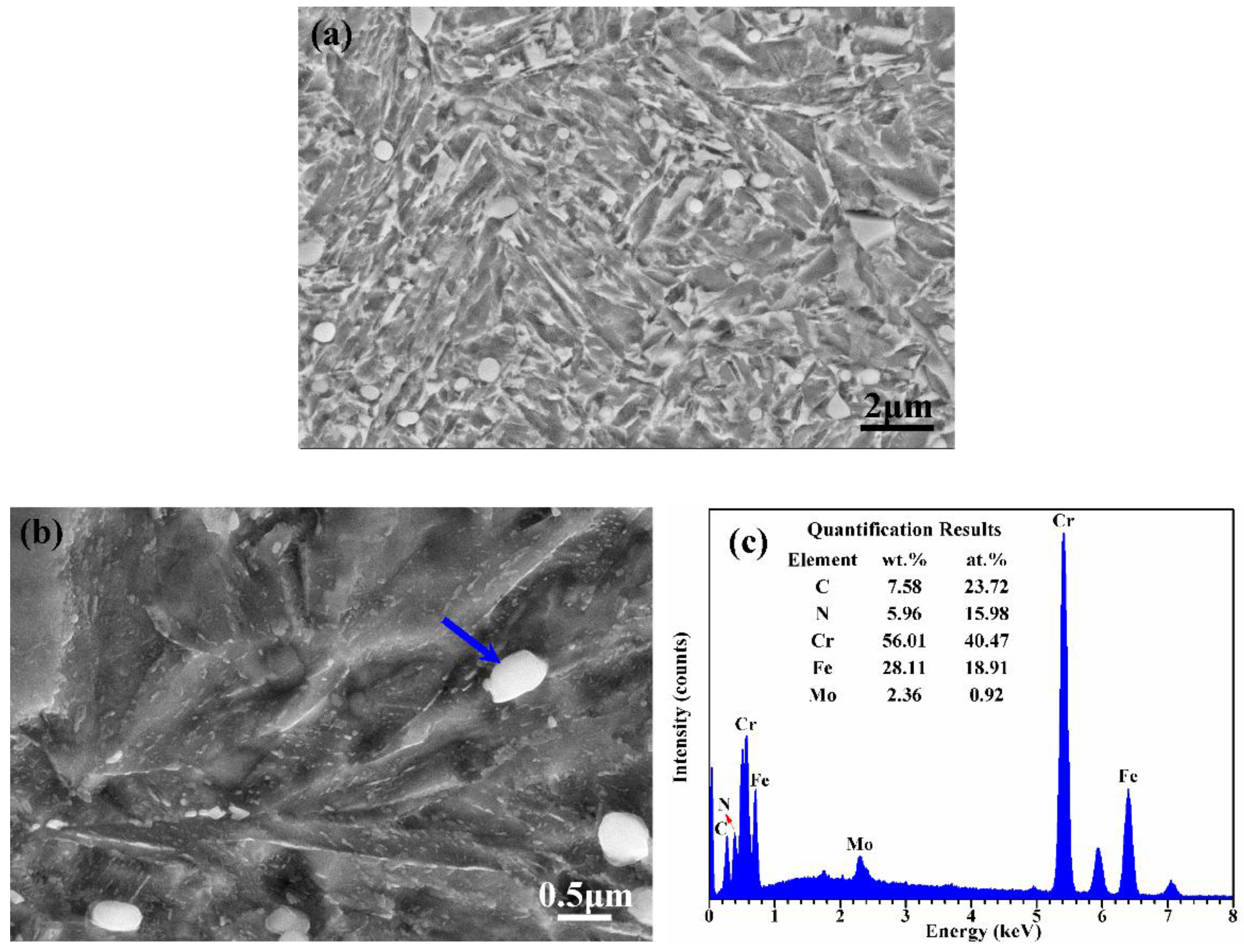
The grain size of SZ is larger than that of the BM and the case of SZ-top is the largest. The “onion ring” formed in the middle of SZ. Some carbides and nitrides rich in chromium were found in BM while not observed in SZ.
(3)
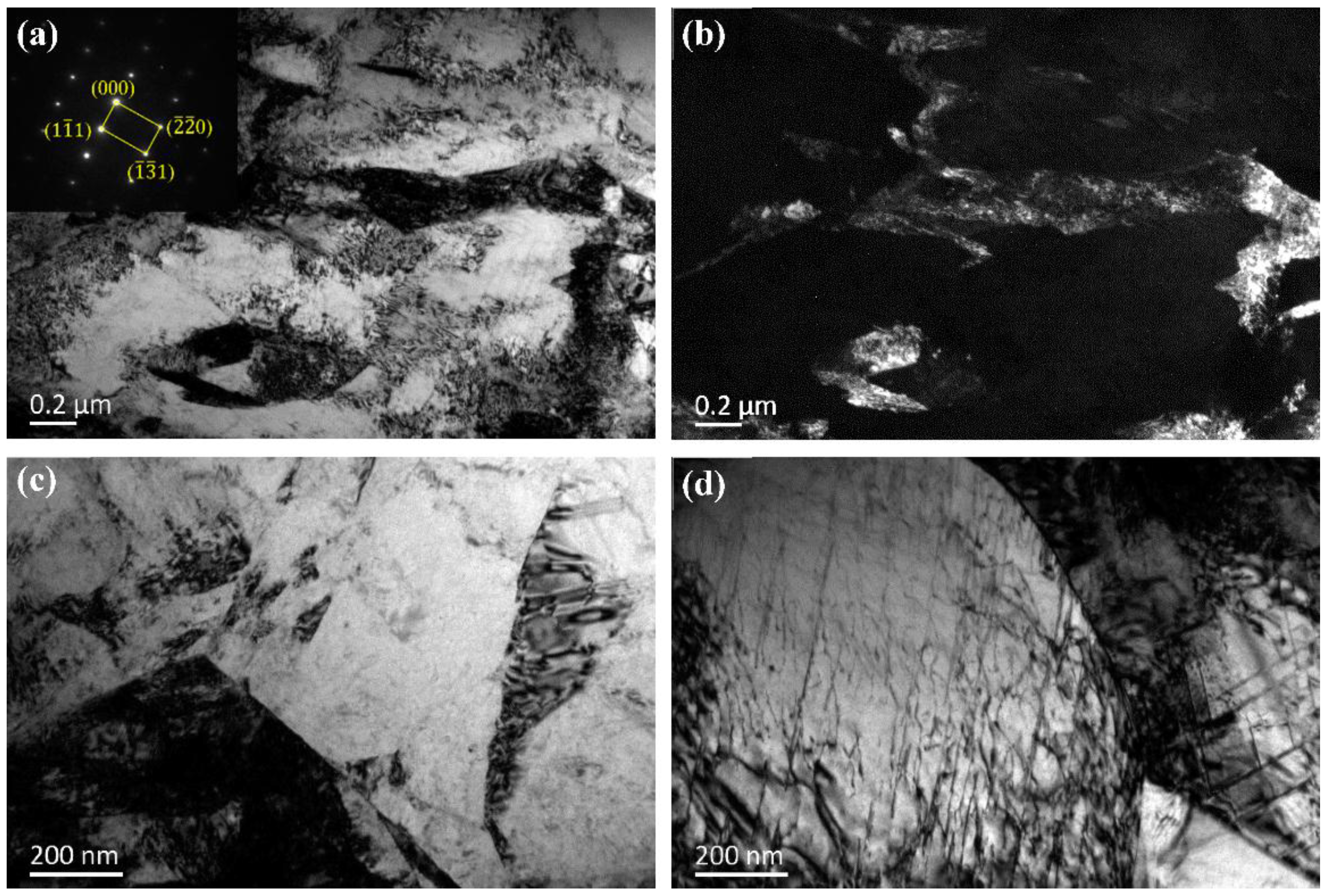
Based on the TEM, XRD and EBSD analysis, the martensitic phase in SZ could transform into austenite phase during FSW process and the higher peak temperature, the greater degree of transformation.
(4)
The hardness of SZ is significantly lower than that of the BM. An abrupt change of hardness defined as hard zone (HZ) was found in TMAZ on AS, and the HZ is attributed to a combination result of temperature, deformation, and material flow behavior.
(5)
The corrosion resistance of SZ is superior to that of BM, which can be attributed to lower precipitation and more LABs. The case of SZ-bottom is slightly higher than that of SZ-top because of the finer grained structure.

Acknowledgments

This work was supported by the National Natural Science Foundation of China (Grant No. 51304041, 51434004, U1435205) and the Fundamental Research Funds for the Central Universities (Grant No. N150204007).

Author Contributions

Xin Geng, Huabing Li, Zhouhua Jiang and Jizhong Li conceived and designed the experiments; Binbin Zhang, Shucai Zhang, Hao Feng and Qi Wang performed the experiments; Binbin Zhang, Qi Wang, Hao Feng and Huabing Li analyzed the data; Huabing Li, Binin Zhang, Shucai Zhang, Hao Feng and Qi Wang contributed to writing and editing of the manuscript.

Conflicts of Interest

The authors declare no conflict of interest.

References

  1. Degallaix, S.; Foct, J.; Hendry, A. Mechanical behaviour of high-nitrogen stainless steels. Mater. Sci. Technol. 1986, 2, 946–950. [Google Scholar] [CrossRef]
  2. Gavriljuk, V.G. Nitrogen in iron and steel. ISIJ Int. 1996, 36, 738–745. [Google Scholar] [CrossRef]
  3. Ma, X.P.; Wang, L.J.; Liu, C.M.; Subramanian, S.V. Microstructure and properties of 13Cr5Ni1Mo0.025Nb0.09V0.06N super martensitic stainless steel. Mater. Sci. Eng. A 2012, 539, 271–279. [Google Scholar] [CrossRef]
  4. Lee, T.H.; Oh, C.S.; Kim, S.J.; Takaki, S. Brittle fracture in austenitic steel. Acta Mater. 2007, 55, 3649–3662. [Google Scholar] [CrossRef]
  5. Berns, H.; Lueg, J. Corrosion behavior and mechanical properties of martensitic stainless steels containing nitrogen. In Proceedings of the First International Conference on High Nitrogen Steels-HNS88, Lille, France, 18–20 May 1988; p. 288.
  6. Woo, I.; Kikuchi, Y. Research on the properties of TIG welded joints of high nitrogen nickel-free austenitic stainless steel and welding wire. ISIJ Int. 2002, 42, 1334–1343. [Google Scholar] [CrossRef]
  7. Ogawa, M.; Hiraoka, K.; Katada, Y.; Sagara, M.; Tsukamoto, S. Chromium Nitride Precipitation Behavior in Weld Heat-affected Zone of High Nitrogen Stainless Steel. ISIJ Int. 2002, 42, 1391–1398. [Google Scholar] [CrossRef]
  8. Ogawa, T.; Hiraoka, K.; Katada, Y.; Sagara, M.; Tsukamoto, S.; Shiga, C. Chromium nitride precipitation behavior in weld heat-affected zone of high nitrogen stainless steel. ISIJ Int. 2002, 20, 107–113. [Google Scholar] [CrossRef]
  9. Woo, I.; Aritoshi, M.; Kikuchi, Y. Metallurgical and Mechanical Properties of High Nitrogen Austenitic Stainless Steel Friction Welds. ISIJ Int. 2002, 42, 401–406. [Google Scholar] [CrossRef]
  10. Park, S.H.C.; Sato, Y.S.; Kokawa, H.; Okamoto, K.; Hirano, S.; Inagaki, M. Rapid formation of the sigma phase in 304 stainless steel during friction stir welding. Scr. Mater. 2003, 49, 1175–1180. [Google Scholar] [CrossRef]
  11. Thomas, W.M.; Nicholas, E.D.; Needhman, J.C.; Murch, M.G.; Temple-Smith, P.; Dawes, C.J. Friction Stir Butt Welding. Int. Pat. Appl. PCT/GB92/02203, 6 December 1991. [Google Scholar]
  12. Celik, S.; Cakir, R. Effect of friction stir welding parameters on the mechanical and microstructure properties of the Al-Cu butt joint. Metals 2016, 6, 133. [Google Scholar] [CrossRef]
  13. Sun, Y.; Tsuji, N.; Fujii, H. Microstructure and mechanical properties of dissimilar friction stir welding between ultrafine grained 1050 and 6061-T6 aluminum alloys. Metals 2016, 6, 249. [Google Scholar] [CrossRef]
  14. Reynolds, A.P.; Tang, W.; Herold, T.G.; Prask, H. Structure, properties and residual stress of 304L stainless steel friction stir welds. Scr. Mater. 2003, 48, 1289–1294. [Google Scholar] [CrossRef]
  15. Sato, Y.S.; Nelson, T.W.; Sterling, C.J. Recrystallization in type 304L stainless steel during friction stirring. Acta Mater. 2005, 53, 637–645. [Google Scholar] [CrossRef]
  16. Sato, Y.S.; Nelson, T.W.; Sterling, C.J.; Steel, R.J.; Peterson, C.O. Microstructure and mechanical properties of friction stir welded SAF 2507 super duplex stainless steel. Mater. Sci. Eng. A 2005, 397, 376–384. [Google Scholar] [CrossRef]
  17. Fujii, H.; Cui, L.; Tsuji, N.; Maeda, M.; Nakata, K.; Nogi, K. Friction stir welding of carbon steels. Mater. Sci. Eng. A 2006, 429, 50–57. [Google Scholar] [CrossRef]
  18. Sato, Y.S.; Yamanoi, H.; Kokawa, H.; Furuhara, T. Microstructural evolution of ultrahigh carbon steel during friction stir welding. Scr. Mater. 2007, 57, 557–560. [Google Scholar] [CrossRef]
  19. Chung, Y.D.; Fujii, H.; Ueji, R.; Tsuji, N. Friction stir welding of high carbon steel with excellent toughness and ductility. Scr. Mater. 2010, 63, 223–226. [Google Scholar] [CrossRef]
  20. Ueji, R.; Fujii, H.; Cui, L.; Nishiokac, A.; Kunishigea, K.; Nogib, K. Friction stir welding of ultrafine grained plain low-carbon steel formed by the martensitic process. Metall. Mater. Trans. A 2006, 423, 324–330. [Google Scholar]
  21. Meshram, S.D.; Madhusudhan Reddy, G.; Pandey, S. Friction stir welding of maraging steel. Mater. Des. 2013, 49, 58–64. [Google Scholar] [CrossRef]
  22. Han, L.; Li, H.; Zhu, Z.; Barbaro, F.; Jiang, L.; Xu, H.; Ma, L. Microstructure and mechanical properties of friction stir welded 18Cr-2Mo ferritic stainless steel thick plate. Mater. Des. 2014, 63, 238–246. [Google Scholar] [CrossRef]
  23. Esmailzadeh, M.; Shamanian, M.; Kermanpur, A.; Saeid, T. Microstructure and mechanical properties of friction stir welded lean duplex stainless steel. Mater. Sci. Eng. A 2013, 561, 486–491. [Google Scholar] [CrossRef]
  24. Nandan, R.; DebRoy, T.; Bhadeshia, H.K.D.H. Recent advances in friction-stir welding—Process, weldment structure and properties. Prog. Mater. Sci. 2008, 53, 980–1023. [Google Scholar] [CrossRef]
  25. Mishra, R.S.; Mab, Z.Y. Friction stir welding and processing. Mater. Sci. Eng. R 2005, 50, 1–78. [Google Scholar] [CrossRef]
  26. Krishnan, K.N. On the formation of onion rings in friction stir welds. Mater. Sci. Eng. A 2002, 327, 246–251. [Google Scholar] [CrossRef]
  27. Jeon, J.J.; Mironov, S.; Sato, Y.S.; Kokawa, H.; Park, S.H.C.; Hirano, S. Grain structure development during friction stir welding of single-crystal austenitic stainless steel. Metall. Mater. Trans. A 2013, 44, 3157–3166. [Google Scholar] [CrossRef]
  28. Du, D.; Fu, R.; Li, Y.; Jing, L.; Ren, Y.; Yang, K. Gradient characteristics and strength matching in friction stir welded joints of Fe–18Cr–16Mn–2Mo–0.85N austenitic stainless steel. Mater. Sci. Eng. A 2014, 616, 246–251. [Google Scholar] [CrossRef]
  29. Miyano, Y.; Fujii, H.; Sun, Y.; Katada, Y.; Kuroda, S.; Kamiya, O. Mechanical properties of friction stir butt welds of high nitrogen-containing austenitic stainless steel. Mater. Sci. Eng. A 2011, 528, 2917–2921. [Google Scholar] [CrossRef]
  30. Park, S.H.C.; Sato, Y.S.; Kokawa, H. Microstructural characterisation of stir zone containing residual ferrite in friction stir welded 304 austenitic stainless steel. Sci. Technol. Weld. Join. 2005, 10, 550–556. [Google Scholar] [CrossRef]
  31. Savolainen, K.; Saukkonen, T.; Hänninen, H. Banding in copper friction stir weld. Sci. Technol. Weld. Join. 2012, 17, 111–115. [Google Scholar] [CrossRef]
  32. Li, H.B.; Jiang, Z.H.; Feng, H.; Zhang, S.C.; Li, L.; Han, P.D.; Misra, R.D.K.; Li, J.Z. Microstructure, mechanical and corrosion properties of friction stir welded high nitrogen nickel-free austenitic stainless steel. Mater. Des. 2015, 84, 291–299. [Google Scholar] [CrossRef]
  33. Ahn, B.W.; Choi, D.H.; Kim, D.J.; Jung, S.B. Microstructures and properties of friction stir welded 409L stainless steel using a Si3N4 tool. Mater. Sci. Eng. A 2012, 532, 476–479. [Google Scholar] [CrossRef]
  34. Sato, Y.S.; Kokawa, H.; Enmoto, M.; Jogan, S. Microstructural evolution of 6063 aluminum during friction-stir welding. Metall. Mater. Trans. A 1999, 30, 2429. [Google Scholar] [CrossRef]
  35. Heinz, B.; Skrotzki, B. Characterization of a friction-stir-welded aluminum alloy 6013. Metall. Mater. Trans. B 2002, 33, 489–498. [Google Scholar] [CrossRef]
  36. Jata, K.V.; Sankaran, K.K.; Ruschau, J.J. Friction-stir welding effects on microstructure and fatigue of aluminum alloy 7050-T7451. Metall. Mater. Trans. A 2000, 31, 2181–2192. [Google Scholar] [CrossRef]
  37. Arbegast, W.J.; Hartley, P.J. Friction stir weld technology development at Lockheed Martin Michoud space systems—An overview. In Proceedings of the Fifth International Conference on Trends in Welding Research, Pine Mountain, GA, USA, 1–5 June 1998; p. 541.
  38. Ghosh, M.; Kumar, K.; Mishra, R.S. Analysis of microstructural evolution during friction stir welding of ultrahigh-strength steel. Scr. Mater. 2010, 63, 851–854. [Google Scholar] [CrossRef]
  39. Prado, R.A.; Murr, L.E.; Shindo, D.J.; Sota, K.F. Tool wear in the friction-stir welding of aluminum alloy 6061 + 20% Al2O3: A preliminary study. Scr. Mater. 2001, 45, 75–80. [Google Scholar] [CrossRef]
  40. Hansen, N.; Huang, X.; Hughes, D.A. Microstructural evolution and hardening parameters. Mater. Sci. Eng. A 2001, 317, 3–11. [Google Scholar] [CrossRef]
  41. Fujii, H.; Ueji, R.; Takada, Y.; Kitahara, H.; Tsuji, N.; Nakata, K.; Nogi, K. Friction Stir Welding of Ultrafine Grained Interstitial Free Steels. Mater. Trans. JIM 2006, 47, 239–242. [Google Scholar] [CrossRef]
  42. Lee, H.; Kim, C.; Song, J.H. An evaluation of global and local tensile properties of friction-stir welded DP980 dual-phase steel joints using a digital image correlation method. Metals 2015, 8, 8424–8436. [Google Scholar] [CrossRef]
  43. Sato, Y.S.; Park, S.H.C.; Kokawa, H. Distribution of tensile property and microstructure in friction stir weld of 6063 aluminum. Metall. Mater. Trans. A 2001, 32, 3023–3031. [Google Scholar] [CrossRef]
  44. Jeon, J.; Mironov, S.; Sato, Y.S.; Kokawa, H.; Park, S.H.C.; Hirano, S. Friction stir spot welding of single-crystal austenitic stainless steel. Acta Mater. 2011, 59, 7439–7449. [Google Scholar] [CrossRef]
  45. Ozekcin, A.; Jin, H.W.; Koo, J.Y.; Bangaru, N.V.; Ayer, R. A Microstructural Study of Friction Stir Welded Joints of Carbon Steels. Int. J. Offshore Polar Eng. 2004, 14, 284–288. [Google Scholar]
  46. Sowards, J.W.; Herold, T.G.; McColskey, J.D.; Pereira, V.F.; Ramirez, A.J. Characterization of mechanical properties, fatigue-crack propagation, and residual stresses in a microalloyed pipeline-steel friction-stir weld. Mater. Des. 2015, 88, 632–642. [Google Scholar] [CrossRef]
  47. Hansen, N.; Huang, X.; Hughes, D.A. Effect of Grain Boundaries and Grain Orientation on Structure and Properties. Mater. Sci. Eng. A 2001, 317, 3–11. [Google Scholar] [CrossRef]
  48. Ralston, K.D.; Birbilis, N. Effect of Grain Size on Corrosion: A Review. Corrosion 2010, 66, 075005–075013. [Google Scholar] [CrossRef]
  49. Dinh, L.; Earthman, J.C.; Lund, I.; Mohamed, F.A.; Roy, I.; Yang, H.W. Possible origin of superior corrosion resistance for nanocrystalline Ni. Scr. Mater. 2008, 59, 305–308. [Google Scholar]
  50. Gupta, R.K.; Raman, R.K.S.; Koch, C.C.; Murty, B.S. Effect of nanocrystalline structure on the corrosion of a Fe20Cr alloy. Int. J. Electrochem. Sci. 2013, 8, 6791–6806. [Google Scholar]
  51. Lu, A.Q.; Zhang, Y.; Li, Y.; Liu, G.; Zang, Q.H.; Liu, C.M. Effect of nanocrystalline and twin boundaries on corrosion behavior of 316 stainless steel using SMAT. Acta Metall. Sin. Engl. Lett. 2006, 19, 183–189. [Google Scholar] [CrossRef]
Figure 1. Appearance of the friction stir welding (FSW) joint.
Metals 06 00301 g001
Figure 2. Schematic for distributed regions of FSW specimen and its relative optical micrographs of different distributed regions: (a) transverse section of joint; (b) base metal (BM); (c) heat-affected zone advancing side (HAZ-AS); (d) thermo-mechanically-affected zone/stir zone advancing side (TMAZ)/(SZ-AS); (e) stir zone top (SZ)-top; (f) SZ-bottom; (g) TMAZ/SZ-retreating side (RS); (h) HAZ-RS.
Metals 06 00301 g002
Figure 3. SEM micrograph of (a) base material; (b) magnified BM and (c) its corresponding EDS analysis (the measurement point is indicated by an arrow).
Metals 06 00301 g003
Figure 4. SEM micrographs of SZ: (a) SZ-top and (b) SZ-bottom.
Metals 06 00301 g004
Figure 5. SEM micrographs of (a) TMAZ/SZ-AS; (b) TMAZ/SZ-RS; (c) magnified band structure from (a) and (d) its corresponding EDS analysis.
Metals 06 00301 g005
Figure 6. TEM microstructure of SZ: (a) bright-field and (b) dark-field TEM micrographs of the austenite and associated diffraction pattern; (c) low density and (d) high dislocation network structure.
Metals 06 00301 g006
Figure 7. XRD profiles of welded sample: (a) SZ-top, (b) SZ-bottom, and (c) BM.
Metals 06 00301 g007
Figure 8. EBSD orientation maps and grain-boundary maps of joint: (a,b) SZ-top; (c,d) SZ-bottom and (e,f) BM.
Metals 06 00301 g008
Figure 9. EBSD phases distribution of joint: (a) SZ-top; (b) SZ-bottom and (c) BM. Red represents austenite phase and blue represents martensitic phase.
Metals 06 00301 g009
Figure 10. Micro-hardness distributions of joint through (a) horizontal and (b) vertical directions.
Metals 06 00301 g010
Figure 11. Potentiodynamic polarization curves of BM, SZ-top and SZ-bottom in 3.5 wt. % NaCl solution at 25 °C ± 0.5 °C.
Metals 06 00301 g011
Figure 12. EIS spectrum of BM, SZ-top and SZ-bottom in 3.5 wt. % NaCl solution at 25 °C ± 0.5 °C: (a) Nyquist plots; (b) Bode plots.
Metals 06 00301 g012
Table 1. Chemical composition of high nitrogen martensitic stainless steel 30Cr15Mo1N (wt. %).
CCrMoNNiMnSiFe
0.30615.381.040.380.080.430.5Bal.
Table 2. Equivalent circuit parameters for BM, SZ-top and SZ-bottom in 3.5 wt. % NaCl solution at 25 °C ± 0.5 °C.
SpecimensRs/(Ω·cm−2)CPERp/(Ω·cm−2)
n(0–1)Q0/(S·sn·cm−2)
BM4.9130.89393.673 × 10−51.852 × 10⁵
SZ-top7.6930.88153.037 × 10−52.881 × 10⁵
SZ-bottom3.8010.87833.358 × 10−53.018 × 10⁵

