
A Lightweight Structure Redesign Method Based on Selective Laser Melting

Abstract
:1. Introduction
2. Experimental Section
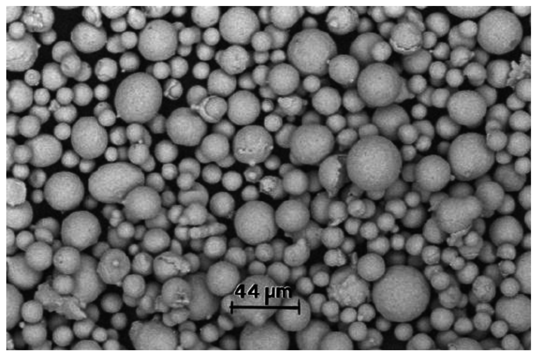
2.1. Materials
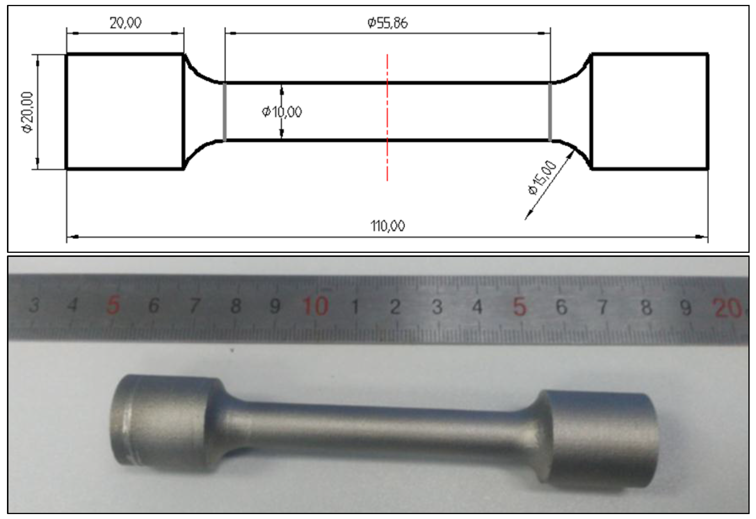
2.2. Process of Tensile Test
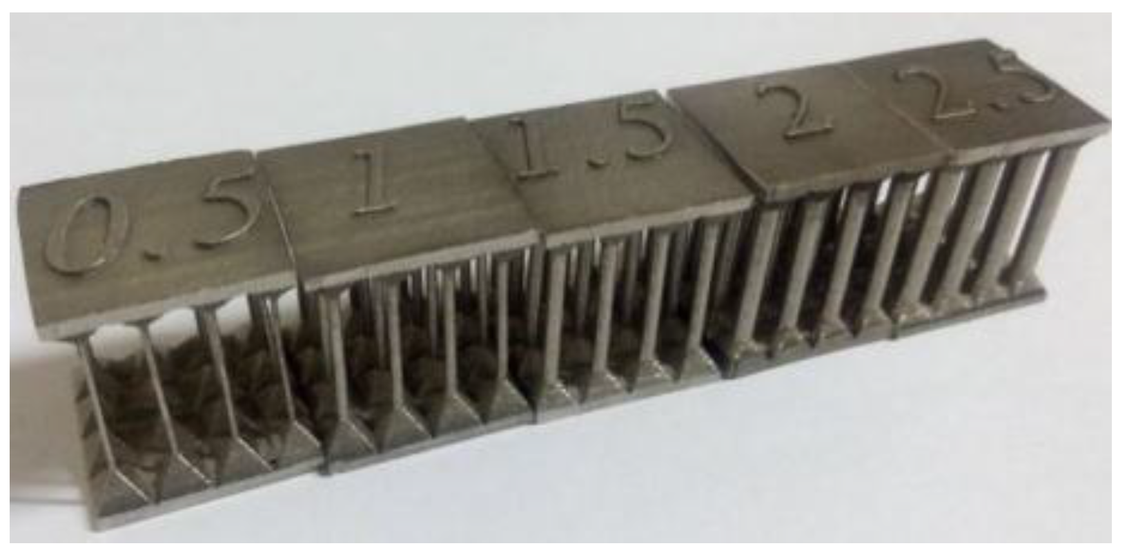
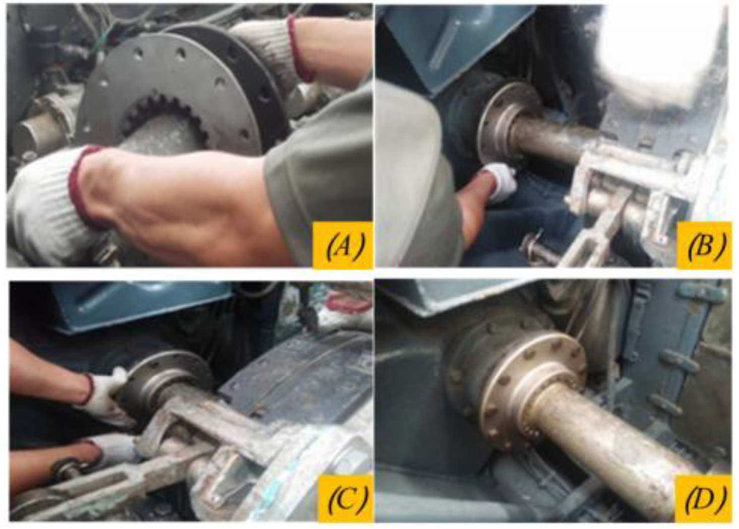
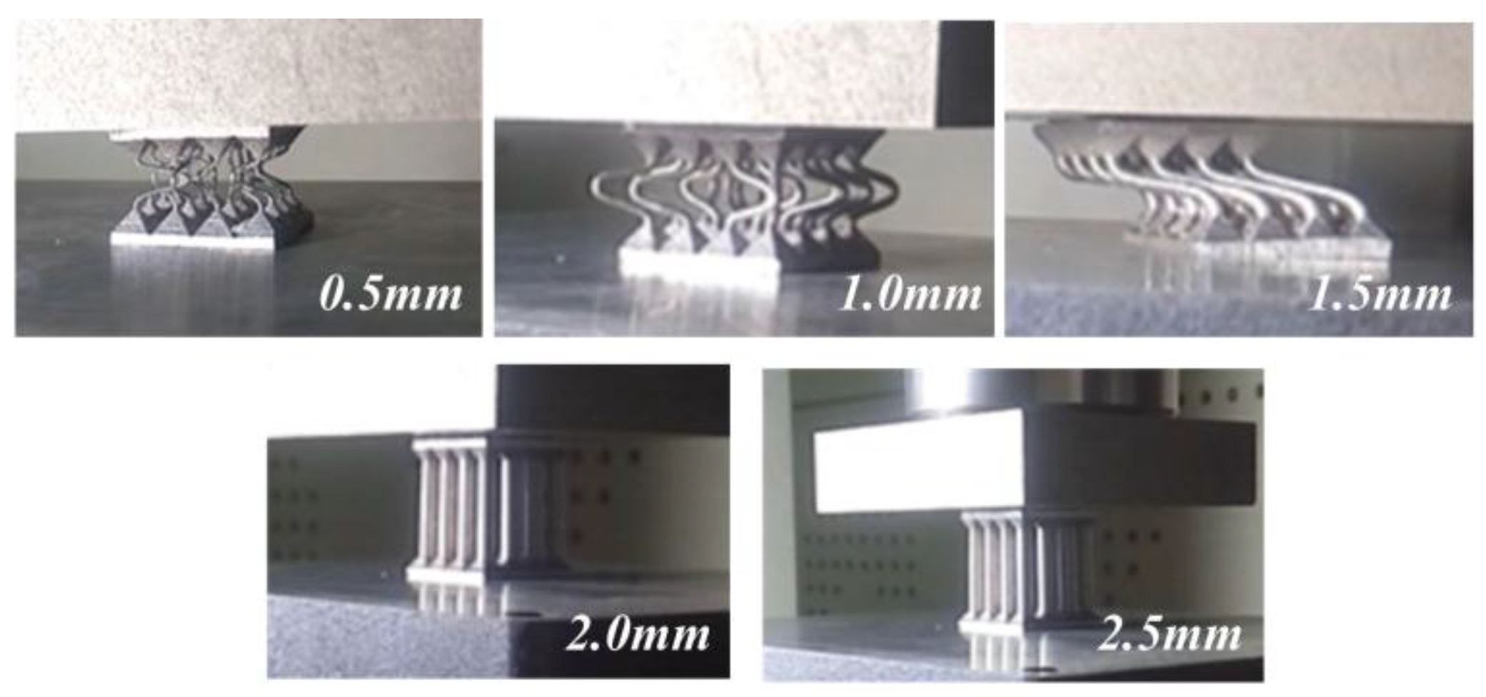
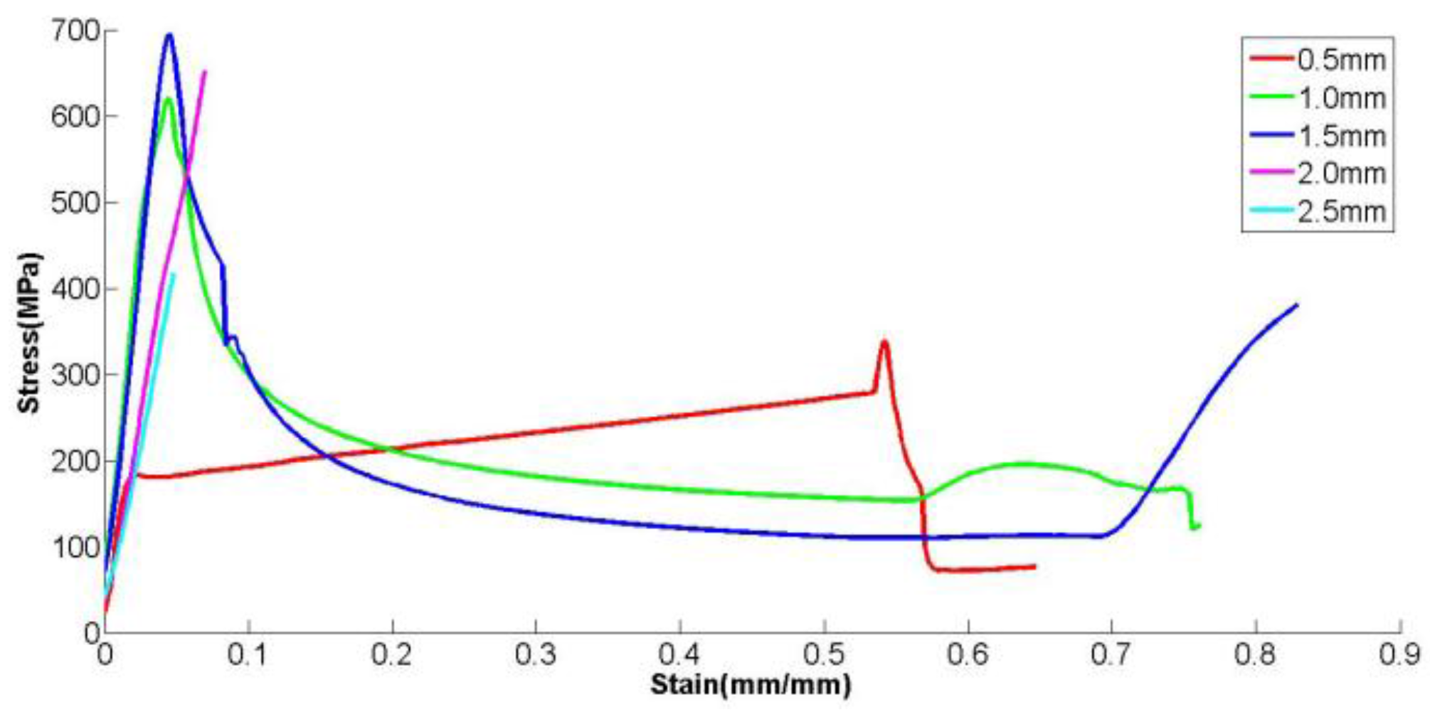
2.3. Compression Test of Lattice Structure
3. Lightweight Parts Redesign Method
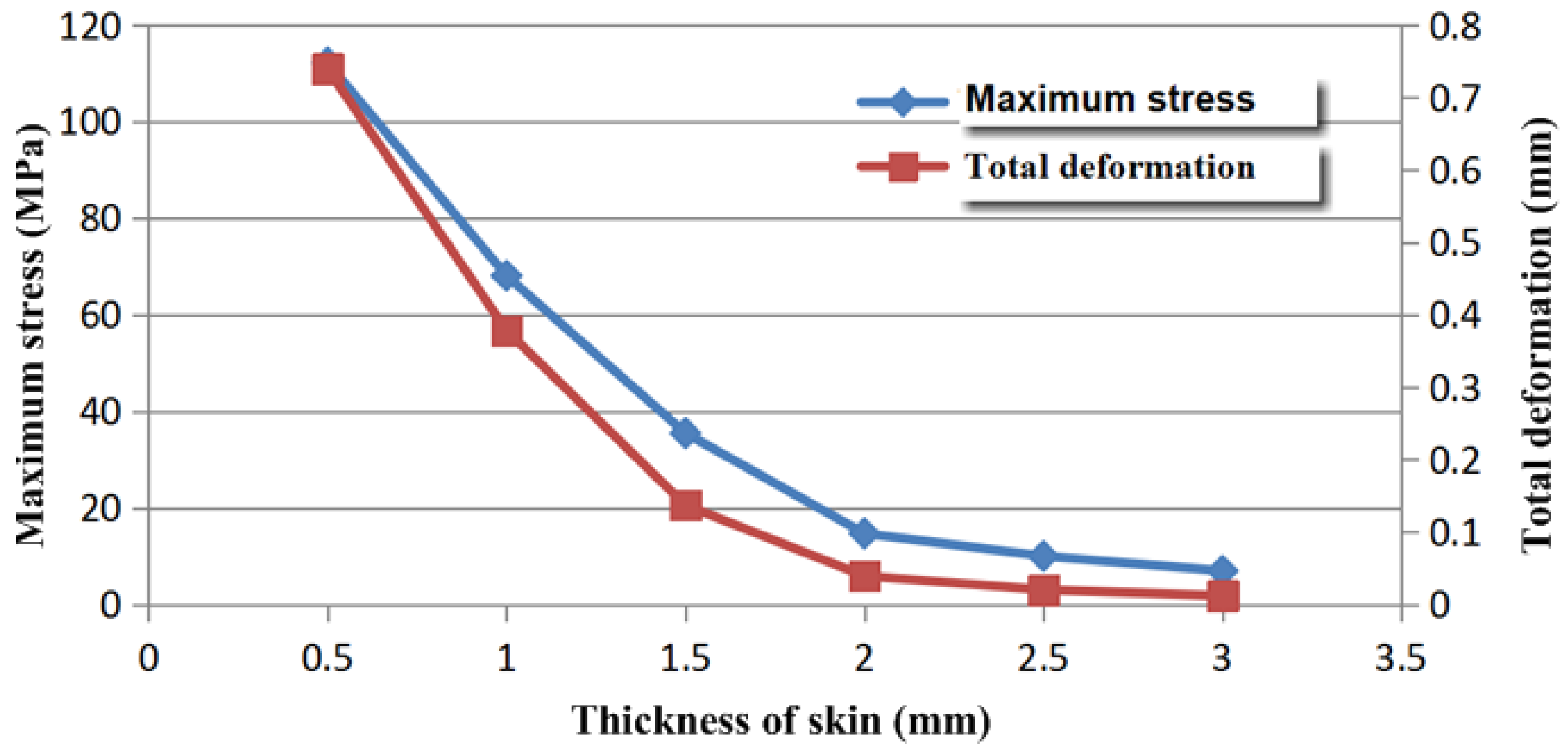
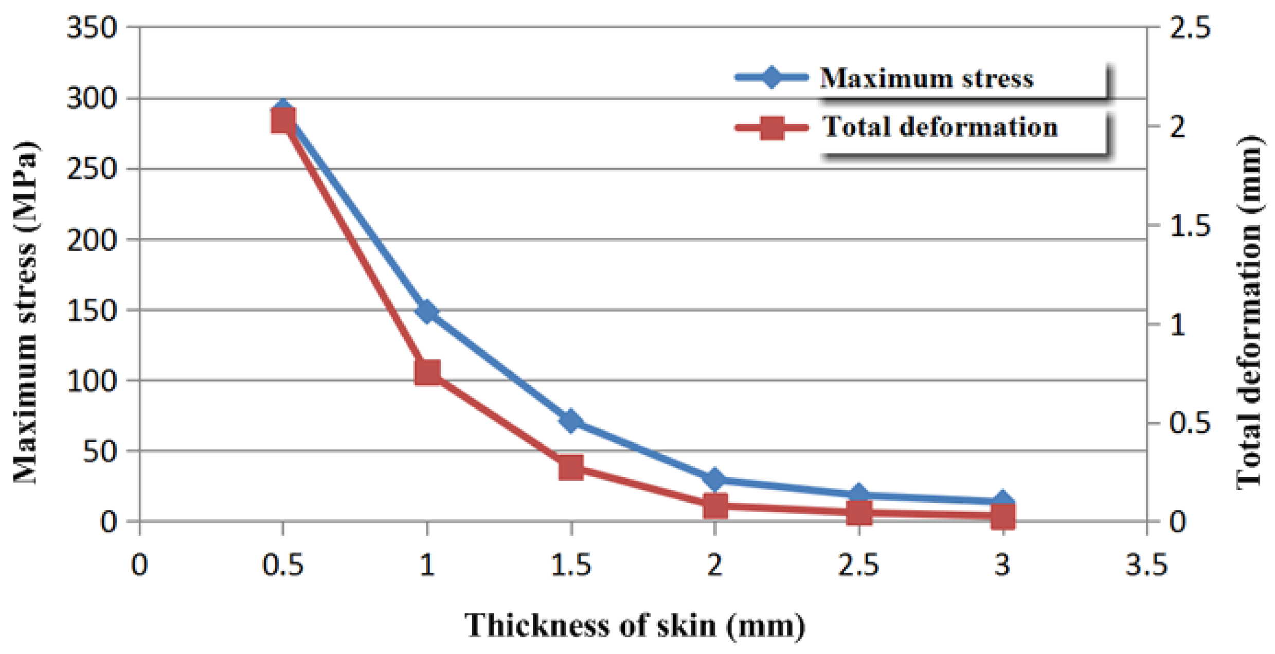
3.1. Design of Skin
3.2. Parts Disassembly and Framework Design
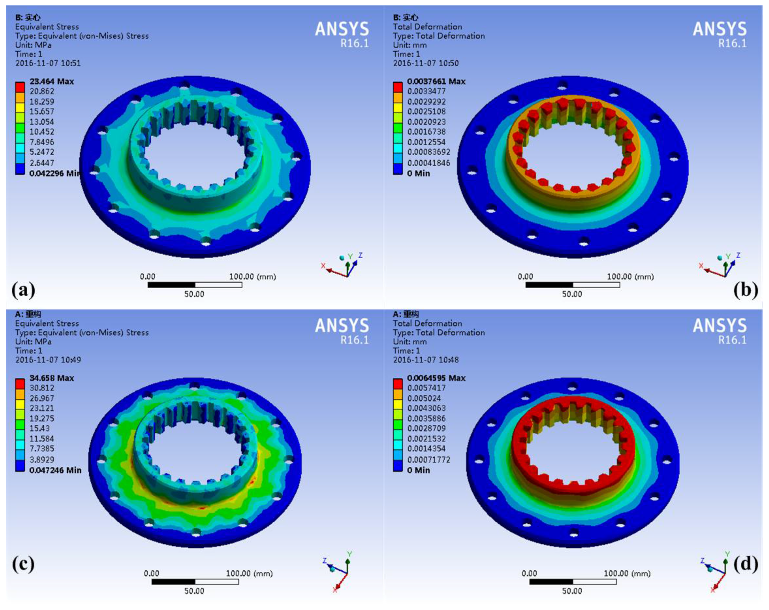
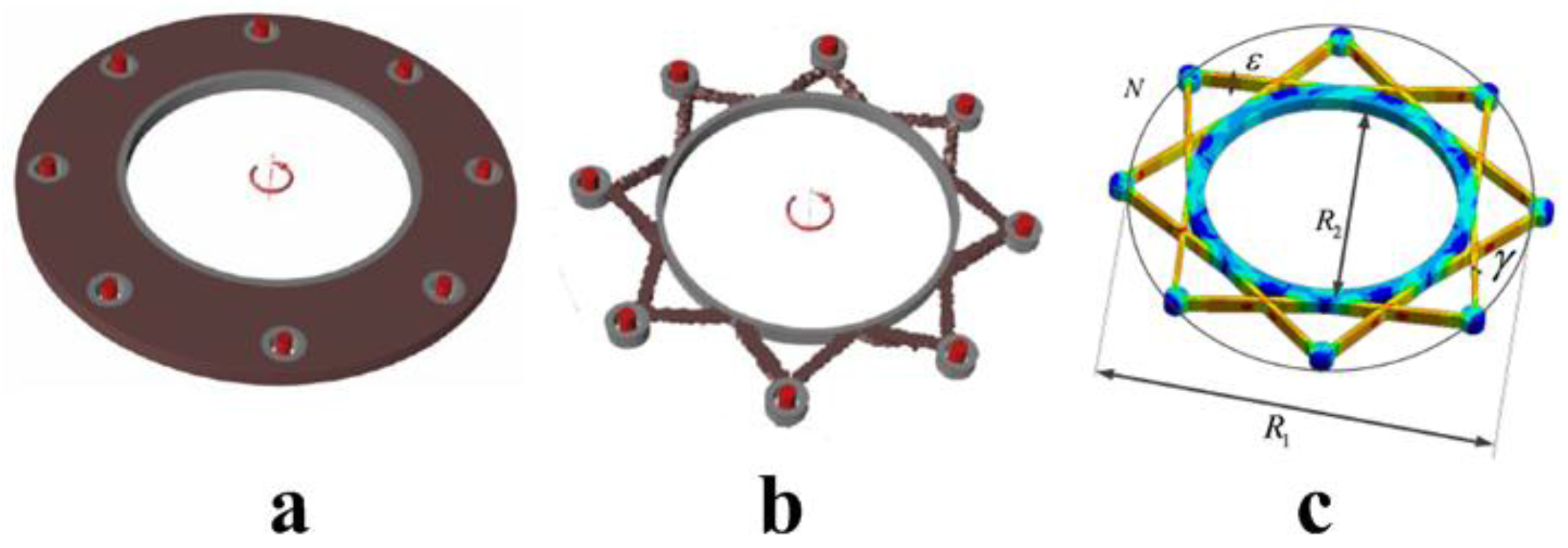
3.2.1. Flange Frame with Torque
- (1)
- Objective function: minimum structure mass
- (2)
- Condition: flange bears torsion load
- (3)
- Boundary conditions: the bolt holes are fixed and the inner surface of the flange is applied to the torque
- (4)
- Design space: brown region in graph
- (5)
- Minimum thickness: 0.006 m
- (6)
- Design constraints: meeting the strength requirements with minimum mass
- N: number of mounting holes;
- D1: location diameter of mounting holes;
- D2: diameter of inner ring;
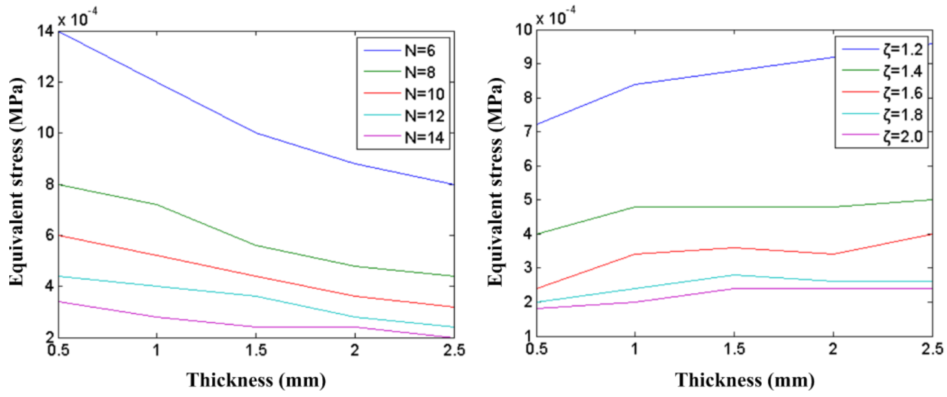
- ε: thickness of flange;
- ζ: ratio of outer and inner ring;
- γ: thickness of dowel bar;
- μ: equivalent stress;
- M: applied torque;
- σs: yield strength of material
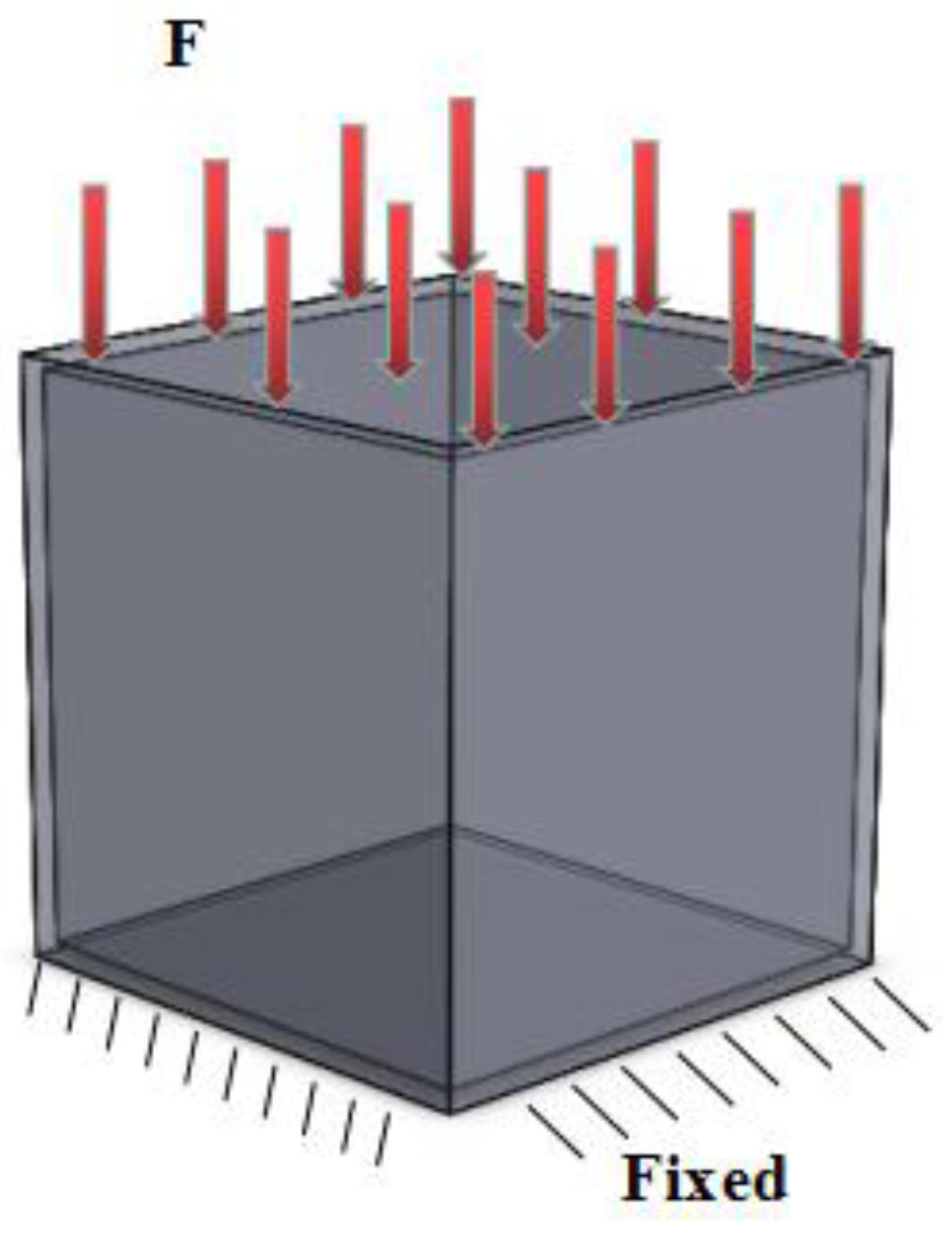
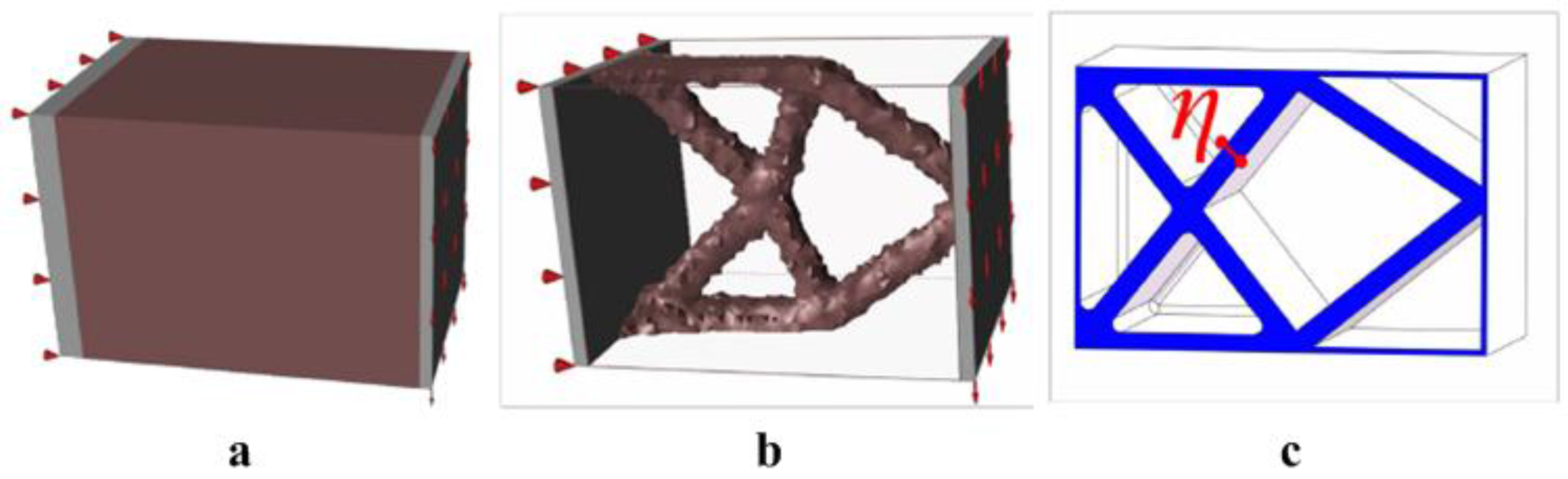
3.2.2. Rectangular Frame with Bending Moment
- (1)
- Objective function: minimum structure mass
- (2)
- Condition: cuboid bearing bending load
- (3)
- Boundary conditions: the left surface is fixed and the right surface is applied to the surface force
- (4)
- Design space: brown region in graph
- (5)
- Minimum thickness: 0.006 m
- (6)
- Design constraints: meeting the strength requirements with minimum mass
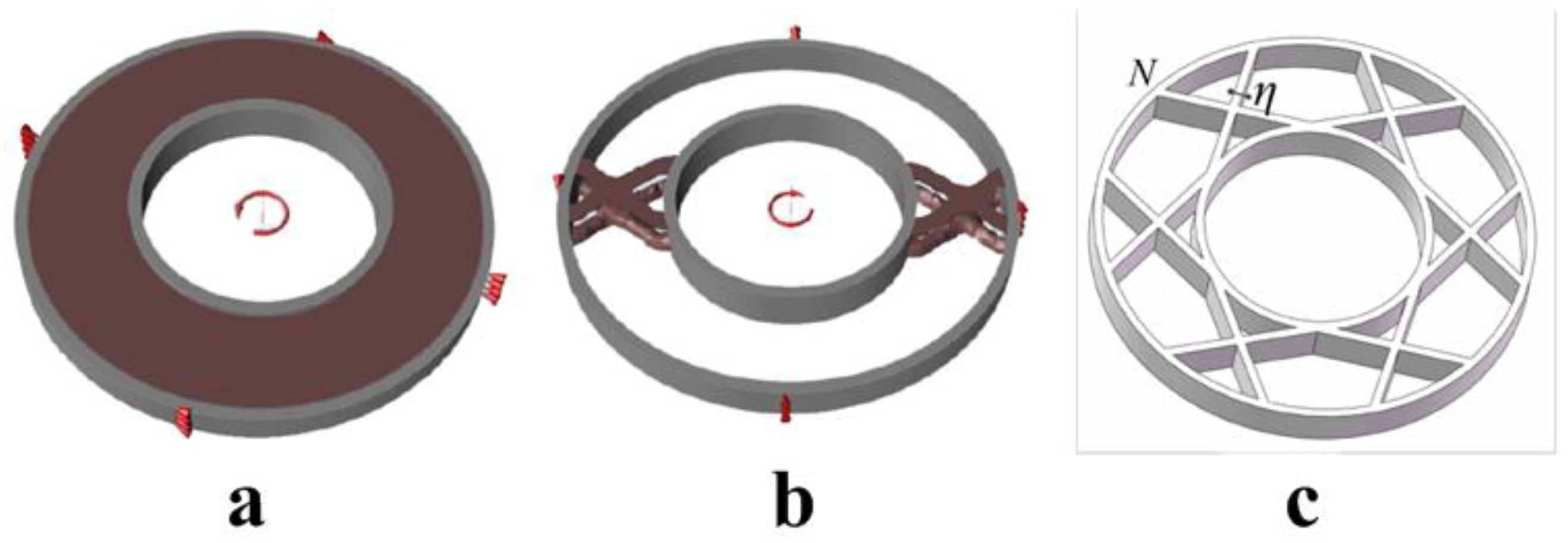
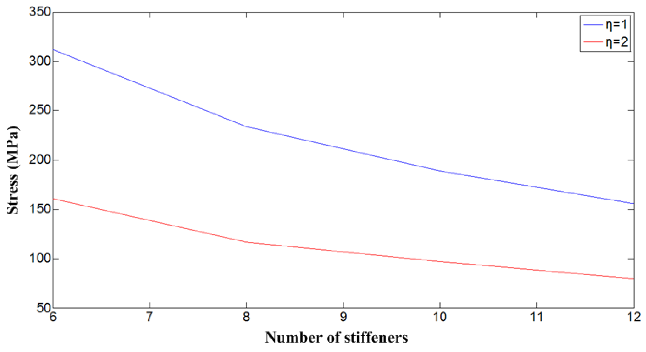
3.2.3. Ring Frame with Torque
- (1)
- Objective function: minimum structure mass
- (2)
- Condition: inner race bearing torsion load
- (3)
- Boundary conditions: the outer ring is fixed and the inner race is applied to torque
- (4)
- Design space: brown region in graph
- (5)
- Minimum thickness: 0.006 m
- (6)
- Design constraints: meeting the strength requirements with minimum mass
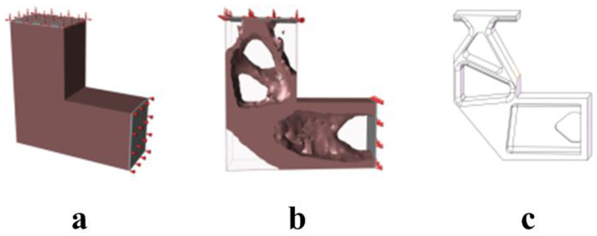
3.2.4. L-Shape Frame with Bending Moment
- (1)
- Objective function: minimum structure mass
- (2)
- Condition 1: one end is fixed and the other end is applied to the vertical load;
- (3)
- Condition 2: one end is fixed and the other end is applied to the horizontal load
- (4)
- Boundary condition: the right boundary is fixed and the left surface is applied to the surface force
- (5)
- Design space: brown region in graph
- (6)
- Minimum thickness: 0.006 m
- (7)
- Design constraints: meeting the strength requirements with minimum mass
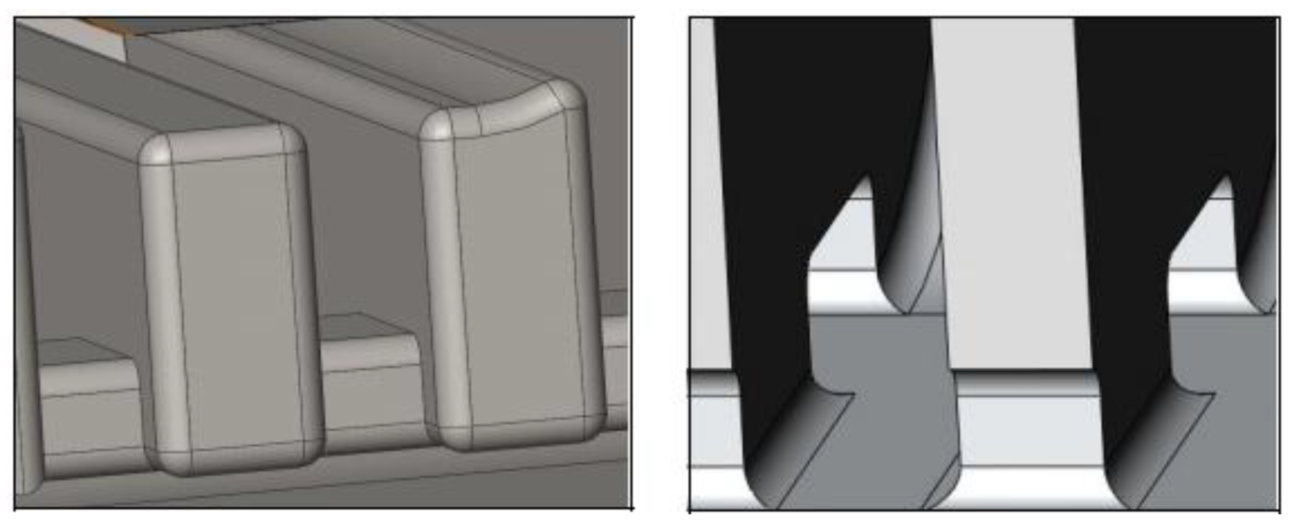
3.3. Detail Design
3.4. Application
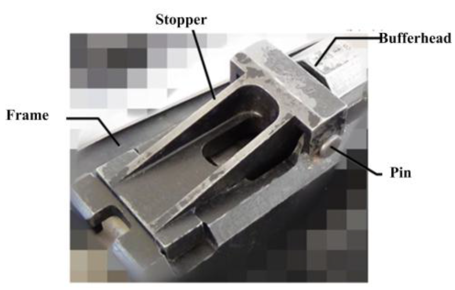
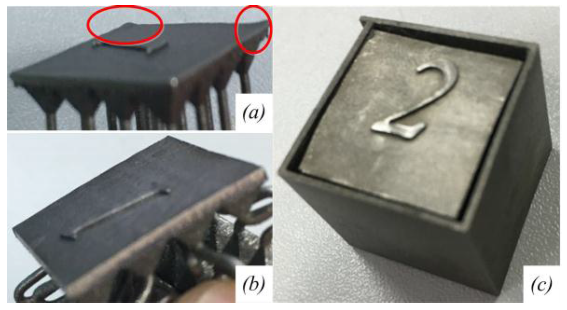
3.4.1. Case 1: Stopper
3.4.2. Case 2: Connecting Plate
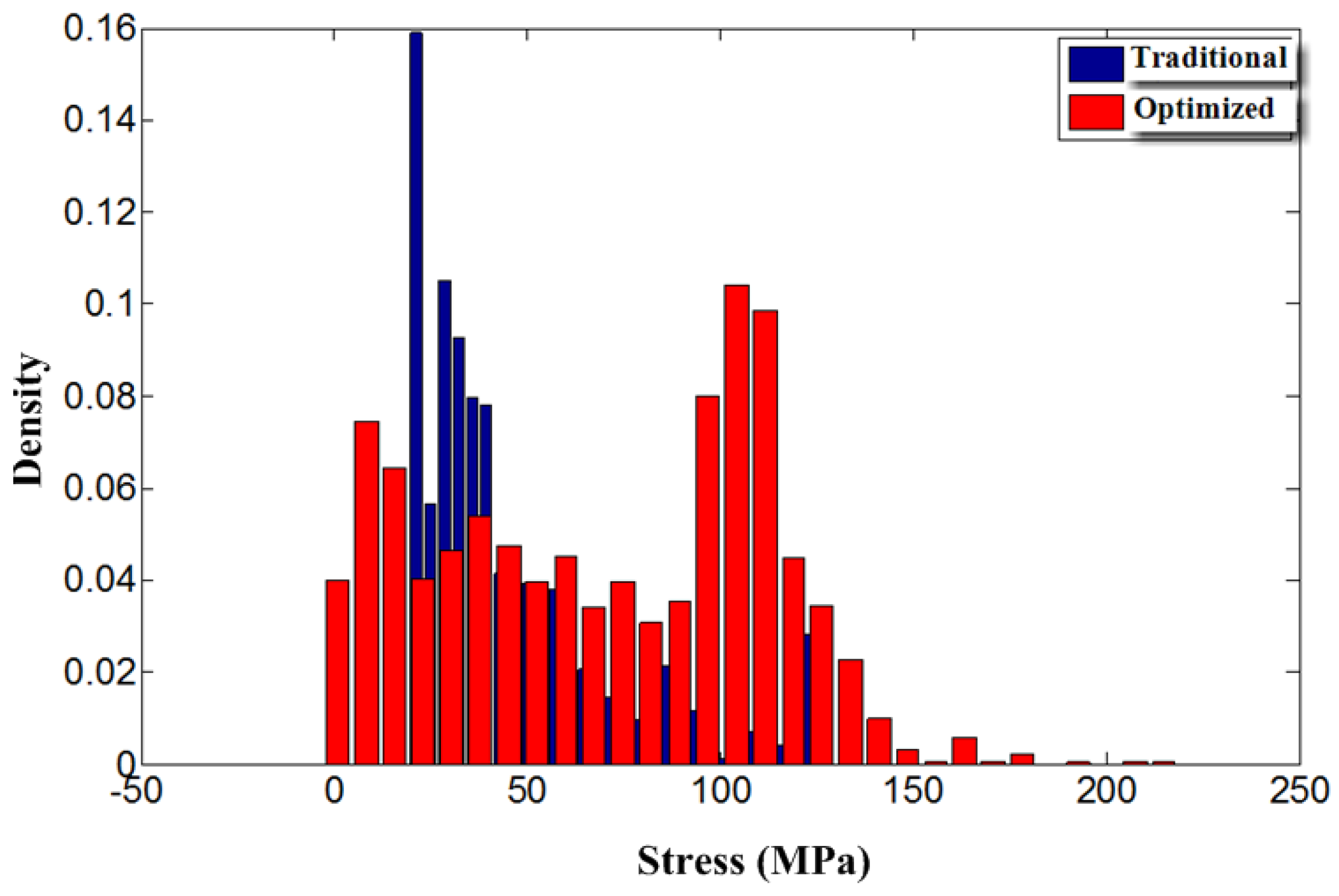
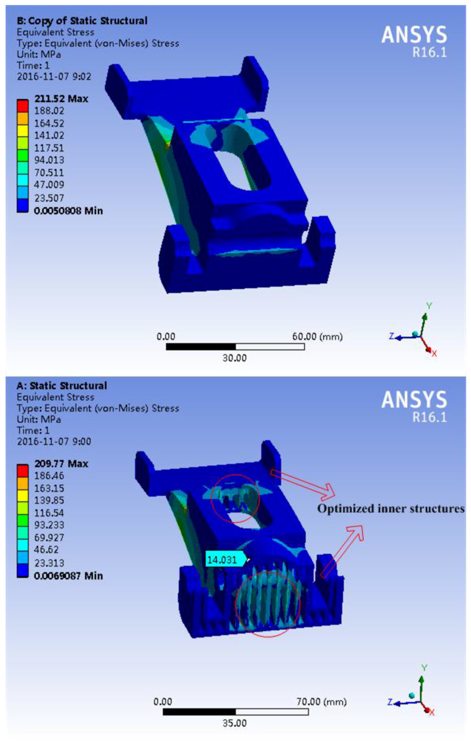
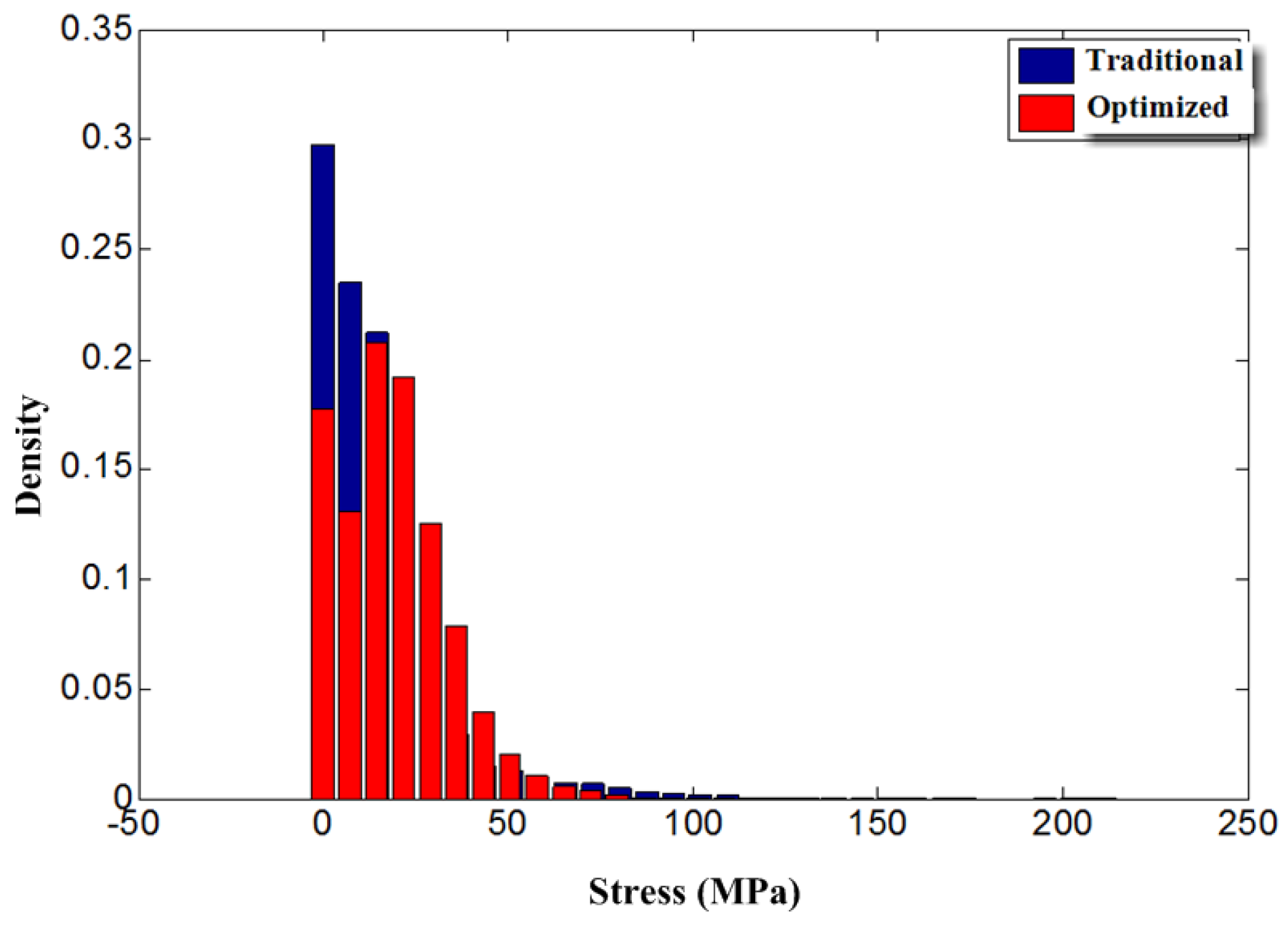
4. Results and Discussion
5. Conclusions
Acknowledgments
Author Contributions
Conflicts of Interest
Nomenclature
| D1 | location diameter of mounting hole |
| D2 | diameter of inner ring |
| L | fracture length |
| L0 | initial length |
| N | number of mounting hole |
| P | maximum load |
| S | section area |
| γ | thickness of dowel bar |
| σ | section stress |
| ε | elongation percentage |
| η | thickness of frame |
References
- Kruth, J.P.; Froyen, L.; Vaerenbergh, J.V.; Mercelis, P.; Rombouts, M.; Lauwers, B. Selective laser melting of iron-based powder. J. Mater. Process. Technol. 2004, 149, 616–622. [Google Scholar] [CrossRef]
- Parthasarathy, J.; Starly, B.; Raman, S.; Christensen, A. Mechanical evaluation of porous titanium (Ti6Al4V) structures with electron beam melting (EBM). J. Mech. Behav. Biomed. Mater. 2010, 3, 249–259. [Google Scholar] [CrossRef] [PubMed]
- Harrysson, O.L.A.; Cansizoglu, O.; Marcellin-Little, D.J.; Cormier, D.R.; West, H.A. Direct metal fabrication of titanium implants with tailored materials and mechanical properties using electron beam melting technology. Mater. Sci. Eng. C 2008, 28, 366–373. [Google Scholar] [CrossRef]
- Evans, A.G.; Hutchinson, J.W.; Fleck, N.A.; Ashby, M.F.; Wadley, H.N.G. The topological design of multifunctional cellular metals. Prog. Mater. Sci. 2001, 46, 309–327. [Google Scholar] [CrossRef]
- Cansizoglu, O.; Harrysson, O.; Cormier, D.; West, H.; Mahale, T. Properties of Ti–6Al–4V non-stochastic lattice structures fabricated via electron beam melting. Mater. Sci. Eng. A 2008, 492, 468–474. [Google Scholar] [CrossRef]
- Campanelli, S.L.; Contuzzi, N.; Ludovico, A.D.; Caiazzo, F.; Cardaropoli, F.; Sergi, V. Manufacturing and Characterization of Ti6Al4V Lattice Components Manufactured by Selective Laser Melting. Materials 2014, 7, 4803–4822. [Google Scholar] [CrossRef]
- Wang, D.; Yang, Y.; Liu, R.; Xiao, D.; Sun, J. Study on the designing rules and processability of porous based on selective laser melting. J. Mater. Process. Technol. 2013, 213, 1734–1742. [Google Scholar] [CrossRef]
- Hernandez-Nava, E.; Smith, C.J.; Derguti, F.; Tammas-Williams, S.; Leonard, F.; Withers, P.J.; Todd, I.; Goodall, R. The effect of defects on the mechanical response of Ti-6Al-4V cubic lattice structures fabricated by electron beam melting. Acta Mater. 2016, 108, 279–292. [Google Scholar] [CrossRef]
- Mahshid, R.; Hansen, H.N.; Hojbjerre, K.L. Strength analysis and modeling of cellular lattice structures manufactured using selective laser melting for tooling applications. Mater. Des. 2016, 104, 276–283. [Google Scholar] [CrossRef] [Green Version]
- Sing, S.L.; Yeong, W.Y.; Wiria, F.E.; Tay, B.Y. Characterization of Titanium Lattice Structures Fabricated by Selective Laser Melting Using an Adapted Compressive Test Method. Exp. Mech. 2016, 56, 735–748. [Google Scholar] [CrossRef]
- Brandt, M.; Sun, S.J.; Leary, M.; Feih, S.; Elambasseril, J.; Liu, Q.C. High-Value SLM Aerospace Components: From Design to Manufacture. Adv. Mater. Res. 2013, 633, 135–147. [Google Scholar] [CrossRef]
- Xiao, D.; Yang, Y.; Su, X.; Wang, D.; Luo, Z. Topology Optimization of Microstructure and Selective Laser Melting fabrication for Metallic Biomaterial Scaffolds. Trans. Nonferr. Met. Soc. China 2012, 22, 2554–2561. [Google Scholar] [CrossRef]


| Thickness (mm) | Load (N) | Maximum Stress (MPa) | Maximum Strain (mm) | Weight (g) |
|---|---|---|---|---|
| 0.5 | 500 | 112.4 | 0.73937 | 238 |
| 1000 | 290.75 | 2.028 | ||
| 1 | 500 | 68.054 | 0.37832 | 470 |
| 1000 | 148.36 | 0.75461 | ||
| 1.5 | 500 | 35.469 | 0.13709 | 699 |
| 1000 | 70.939 | 0.27418 | ||
| 2 | 500 | 14.705 | 0.039352 | 922 |
| 1000 | 29.411 | 0.078705 | ||
| 2.5 | 500 | 10.02 | 0.020339 | 1141 |
| 1000 | 18.385 | 0.043148 |
| Number | Design Objects | Shape | Load | Design Parameters | Result |
|---|---|---|---|---|---|
| 0 |  | Skin | Thickness of skin β |  | |
| 1 |  | L shape | Bending moment | Thickness of frame λ |  |
| 2 |  | Rectangular | Pressure | Thickness of frame η Number of frame N1 |  |
| 3 |  | Rectangular | Pressure | Thickness of frame α Number of frame N2 |  |
| 4 |  | Thin-wall structure | ∞ |  |
| Number | Design Objects | Shape | Load | Design Parameters | Result |
|---|---|---|---|---|---|
| 1 |  | Flange | Torque | Thickness of frame θ |  |
| 2 |  | Ring | Torque | Thickness of frame ν Number of frame N3 |  |
| 3 |  | Spline | Stress | ∞ |  |
| Material | Process | Yield Strength/MPa | Tensile Strength/MPa | Elongation | |
|---|---|---|---|---|---|
| IN718 | cast | 1100 | 1340 | 12% | |
| SLM | X–Y | 780 | 1069.6 | 30.9% | |
| Z | 634 | 980 | - | ||
| Number | Equivalent Diameter/mm | Yield Stress/MPa | Equivalent Stiffness/GPa |
|---|---|---|---|
| 0.5 mm | 2 | 180 (First) 338 (second) | 49.03 |
| 1.0 mm | 4 | 620.2 | 63.85 |
| 1.5 mm | 6 | 694 | 57.33 |
| 2.0 mm | 8 | 35.60 | |
| 2.5 mm | 10 | 30.45 |
© 2016 by the authors; licensee MDPI, Basel, Switzerland. This article is an open access article distributed under the terms and conditions of the Creative Commons Attribution (CC-BY) license (http://creativecommons.org/licenses/by/4.0/).
Share and Cite
Tang, L.; Wu, C.; Zhang, Z.; Shang, J.; Yan, C. A Lightweight Structure Redesign Method Based on Selective Laser Melting. Metals 2016, 6, 280. https://doi.org/10.3390/met6110280
Tang L, Wu C, Zhang Z, Shang J, Yan C. A Lightweight Structure Redesign Method Based on Selective Laser Melting. Metals. 2016; 6(11):280. https://doi.org/10.3390/met6110280
Chicago/Turabian StyleTang, Li, Chunbing Wu, Zhixiong Zhang, Jianzhong Shang, and Chao Yan. 2016. "A Lightweight Structure Redesign Method Based on Selective Laser Melting" Metals 6, no. 11: 280. https://doi.org/10.3390/met6110280