
π-Conjugated Materials as the Hole-Transporting Layer in Perovskite Solar Cells


Abstract
:
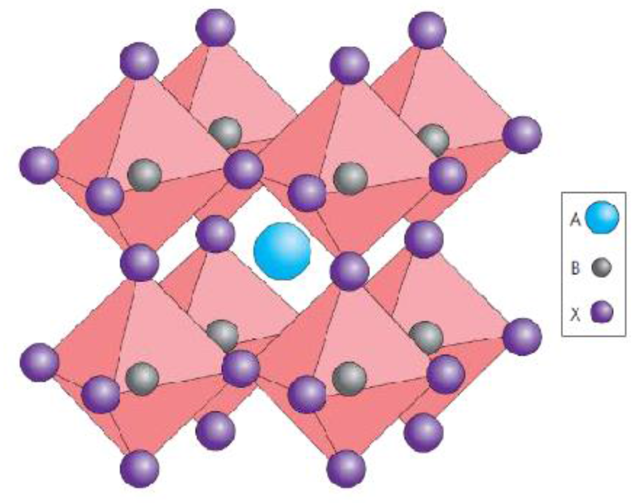
1. Introduction to Hybrid Organometal Halide Perovskite Materials
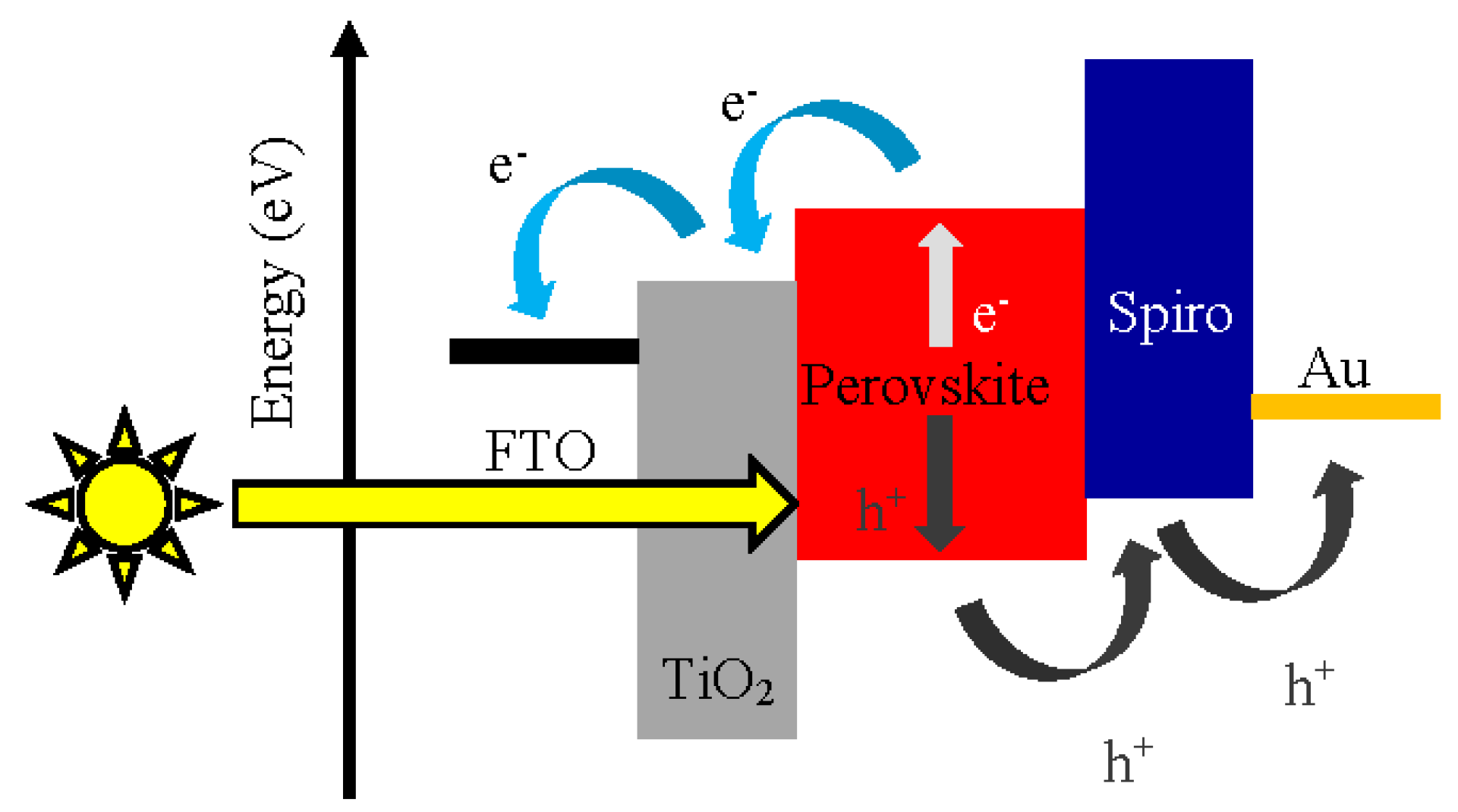
2. Perovskite Solar Cells

3. Characteristics of Hole Transporting Material for Perovskite Solar Cells


| Contact Angles Measurements with Sessile Drop Technique | |
| Liquid | Contact angle |
| Water | 49.8° |
| Ethylene glycol | 26.6° |
| Ethanol | 7.3° |
| Surface Energy (Owens–Wendt Theory) (mJ·m−2) | |
| γS (γd + γp) | 51.92 |
| γd | 6.18 |
| γp | 45.74 |

4. Classical Pi-Conjugated Materials for Hole Transport
4.1. PEDOT:PSS

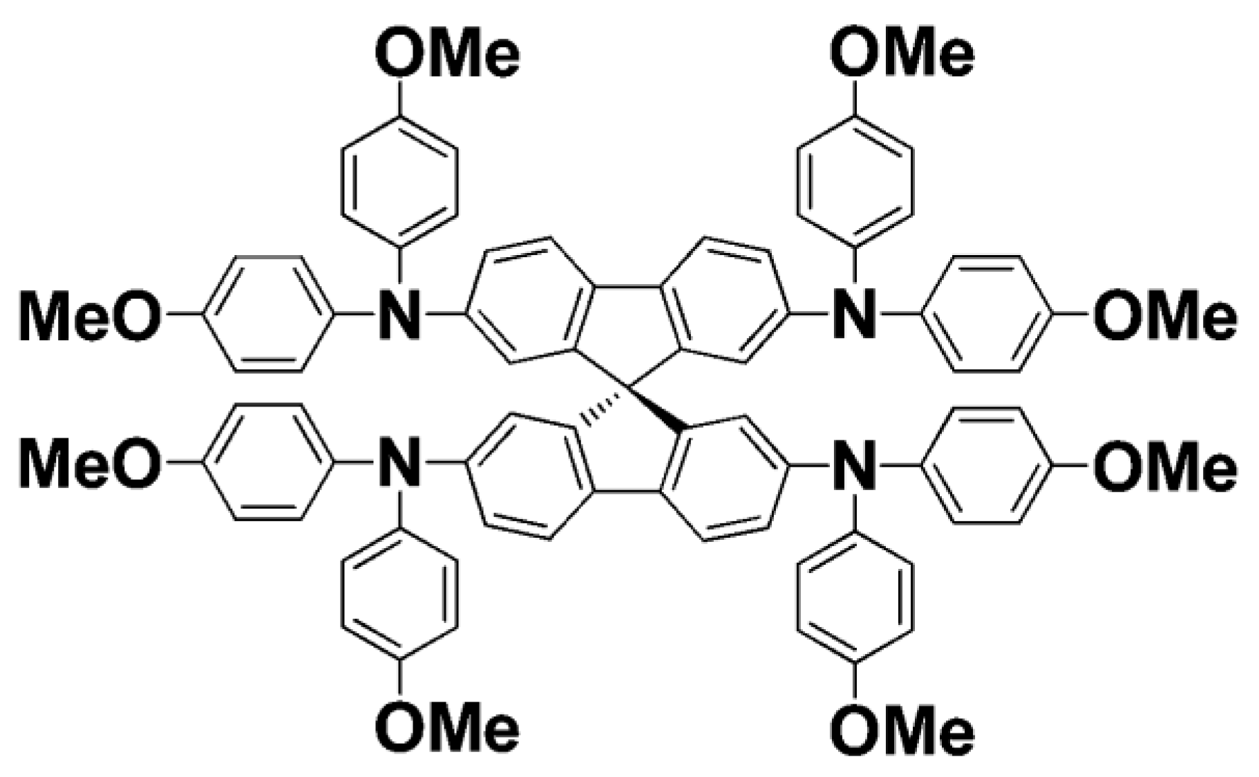
4.2. Spiro-OMeTAD

5. Alternative π-Conjugated Materials for Hole Transport
5.1. Spiro-Core Small Molecules and Inspired Molecules
5.2. EDOT-Core Small Molecules
5.3. Substituted Carbazoles and Derivatives
5.4. Tri-Phenylamine Derivatives
5.5. Phthalocyanine

5.6. Poly-TPD
| Active Surface Area (cm2) | η (%) | JSC (mA·cm2) | VOC (V) | FF (%) |
|---|---|---|---|---|
| 0.065 | 14.8 | 18.2 | 1.09 | 75 |
| 0.95 | 10.9 | 17.9 | 1.07 | 57 |

5.7. PTAA Derivatives
| F4-TCNQ Ratio (wt. %) | JSC (mA·cm−2) | VOC (V) | FF (%) | PCE (%) | Series Resistance (Ω cm2) |
|---|---|---|---|---|---|
| 0 | 21.6 | 1.05 | 65.7 | 14.8 | 9.07 |
| 0.01 | 21.0 | 1.05 | 65.8 | 14.5 | 7.57 |
| 0.1 | 21.5 | 1.05 | 65.5 | 14.8 | 7.72 |
| 1 | 21.6 | 1.09 | 74.0 | 17.5 | 6.07 |
| 2 | 21.0 | 1.09 | 68.2 | 15.6 | 8.56 |
| 10 | 21.2 | 1.09 | 64.1 | 14.8 | 9.77 |
5.8. Polyelectrolytes

5.9. Thiophene Derivative
5.10. Phenylene Derivative
5.11. Furan-Based Small Molecule
5.12. HOMO and LUMO Levels of the Reviewed Materials
| Material | MeN-datpta | CPE-K | EtheneTTPA | MeO2-datpa | PEH-1 | PEH-2 | F101 | CuPc | C12 Carbazole | PEDOT:PSS | Spiro-OMeTAD | MAPbI3−xClx | MAPbI3 | Poly-TPD | TAE-1 | SubPc |
|---|---|---|---|---|---|---|---|---|---|---|---|---|---|---|---|---|
| HOMO | −1.79 | −3.50 | / | −2.29 | −2.73 | −2.8 | −2.40 | −3.5 | / | −3.00 | −2.05 | −3.75 | −3.93 | −2.40 | −2.74 | −3.60 |
| LUMO | −4.4 | −4.90 | −5.02 | −5.02 | −5.16 | −5.17 | −5.18 | −5.2 | −5.29 | −5.20 | −5.22 | −5.3 | −5.43 | −5.40 | −5.44 | −5.60 |
 | ||||||||||||||||
6. Discussion and Perspectives
| Hole Transport Material Name | Representation | Molecule Family | Tested Perovskite Solar Cell | Best VOC (mV) | Best JSC (mA·cm−2) | Best Fill Factor (%) | Best PCE (%) | Surface Area (cm2) | Reference |
|---|---|---|---|---|---|---|---|---|---|
| Spiro-OMeTAD | Spiro Core | Indirect | 1130 | 22.75 | 75.01 | 19.3 | 0.1 | [10] | |
| PEDOT:PSS | EDOT Core | Direct | 1100 | 20.9 | 79 | 18.2 | 0.096 | [17] | |
| Spiro-CPDT |  | Spiro Core | Direct | 971 | 19.3 | 72 | 13.4 | 0.16 | [20] |
| TAE-1 |  | Spiro Inspired | Direct | 885 | 17.22 | 72 | 11.00 | ? | [21] |
| EtheneTTPA |  | Spiro Inspired | Direct | 920 | 21.24 | 67 | 13.09 | 0.16 | [22] |
| PPN |  | Carbazole | Inverted | 990 | 20.1 | 72 | 14.3 | ? | [24] |
| V886 |  | Carbazole | Direct | 1085 | 21.38 | 73 | 16.91 | 0.16 | [25] |
| C12-Carbazole |  | Carbazole | Direct | 860 | 21.13 | 62 | 11.26 | ? | [26] |
| SGT-409 |  | Carbazole | Direct | 938 | 18.63 | 63 | 10.93 | 0.30 | [27] |
| SGT-410 |  | Carbazole | Direct | 984 | 18.55 | 67 | 12.61 | 0.30 | [27] |
| SGT-411 |  | Carbazole | Direct | 997 | 18.60 | 67 | 13.00 | 0.30 | [27] |
| CPE-K | - | Polyelectrolyte | Inverted | 890 | 20.1 | 77 | 12.51 | 0.033 | [38] |
| P3CT-Na |  | Polyelectrolyte | Inverted | 1070 | 21.14 | 73 | 16.6 | 0.09 | [29] |
| PT |  | Thiophene | Inverted | 960 | 21.8 | 78 | 16.1 | ? | [24] |
| PEH-1 |  | Thiophene | Direct | 960 | 16.8 | 72 | 11.7 | 0.16 | [40] |
| PEH-2 |  | Thiophene | Direct | 970 | 19.4 | 72 | 13.5 | 0.16 | [40] |
| PPP |  | Phenylene | Inverted | 1020 | 21.0 | 71 | 15.8 | ? | [24] |
| F101 |  | Furan | Direct | 1100 | 19.63 | 61 | 13.1 | 0.2 | [41] |
| DPEDOT-B[BMPDP]2 |  | EDOT-Core | Direct | 951 | 20.96 | 70 | 14.00 | 0.16 | [23] |
| Poly-TPD |  | - | Inverted | 1090 | 18.2 | 75 | 14.3 | 0.065 | [35] |
| PTAA |  | - | Inverted | 1090 | 21.6 | 74 | 17.5 | ? | [37] |

7. Conclusions
Acknowledgments
Author Contributions
Conflicts of Interest
References
- Gao, P.; Grätzel, M.; Nazeeruddin, M.K. Organohalide lead perovskites for photovoltaic applications. Energy Environ. Sci. 2014, 7, 2448–2463. [Google Scholar] [CrossRef]
- Green, A.M.; Ho-Baillie, A.J.; Snaith, H. The emergence of perovskite solar cells. Nat. Photonics 2014, 8, 506–514. [Google Scholar] [CrossRef]
- Even, J.; Pedesseau, L.; Katan, C.; Kepenekian, M.; Lauret, J.S.; Sapori, D.; Deleport, E. Solid-State Physics Perspective on Hybrid Perovskite. J. Phys. Chem. C 2015, 119, 10161–10177. [Google Scholar] [CrossRef] [Green Version]
- Wehrenfennig, C.; Eperon, G.E.; Johnston, M.B.; Snaith, H.J.; Herz, L.M. High Charge Carrier Mobilities and Lifetimes in Organolead Trihalide Perovskites. Adv. Mat. Res. 2013, 26, 1584–1589. [Google Scholar] [CrossRef]
- Chynoweth, A.G. Surface Space-Charge Layers in Barium Titanate. Phys. Rev. 1656, 102, 705–714. [Google Scholar] [CrossRef]
- Kojima, A.; Teshima, K.; Shirai, Y.; Miyasaka, T. Novel Photoelectrochemical Cell with Mesoscopic Electrodes Sensitized by Lead-halide Compounds. In Proceedings of the 212th ECS Meeting, Washington, DC, USA, 7–12 October 2007.
- Kojima, A.; Teshima, K.; Shirai, Y.; Miyasaka, T. Organometal Halide Perovskites as Visible-Light Sensitizers for Photovoltaic Cells. J. Am. Chem. Soc. 2009, 131, 6050–6051. [Google Scholar] [CrossRef] [PubMed]
- Kim, H.S.; Lee, C.R.; Im, J.H.; Lee, K.B.; Moehl, T.; Marchioro, A.; Moon, S.J.; Humphry-Baker, R.; Yum, J.H.; Moser, E.J.; et al. Lead Iodide Perovskite Sensitized All-Solid-State Submicron Thin Film Mesoscopic Solar Cell with Efficiency Exceeding 9%. Sci. Rep. 2012, 2, 591. [Google Scholar] [CrossRef] [PubMed]
- Lee, M.M.; Teuscher, J.; Miyasaka, T.; Murakami, T.N.; Snaith, H.J. Efficient Hybrid Solar Cells Based on Meso-Superstructured Organometal Halide Perovskites. Science 2012, 338, 643–647. [Google Scholar] [CrossRef] [PubMed]
- Zhou, H.; Chen, Q. Interface engineering of highly efficient perovskite solar cells. Science 2014, 354, 542–546. [Google Scholar] [CrossRef] [PubMed]
- Salim, T.; Sun, S.; Abe, Y.; Krishna, A.; Grimsdale, A.C.; Lam, Y.M. Perovskite-based solar cells: Impact of morphology and device architecture on device performance. J. Mater. Chem. A 2014, 3, 8943–8969. [Google Scholar] [CrossRef]
- Völker, S.; Delgado, J.L. Organic Charge Carriers for Perovskite Solar Cells. ChemSusChem 2015, 8, 3012–3028. [Google Scholar]
- Yu, Z.; Sun, L. Recent Progress on Hole-Transporting Materials for Emerging Organometal Halide Perovskite Solar Cells. Adv. Energy Mater. 2015. [Google Scholar] [CrossRef]
- Jeng, J.Y.; Chiang, Y.F.; Lee, M.H.; Peng, S.R.; Guo, T.F.; Chen, P.; Wen, T.C. CH3NH3PbI3 Perovskite/Fullerene Planar-Heterojunction Hybrid Solar Cells. Adv. Mater. 2013, 25, 3727–3732. [Google Scholar] [CrossRef] [PubMed]
- Sun, S.; Salim, T.; Mathews, N.; Duchamp, M.; Boothroyd, C.; Xing, G.; Sum, T.C.; Lam, Y.M. The origin of high efficiency in low-temperature solution-processable bilayer organometal halide hybrid solar cells. Energy Environ. Sci. 2013, 7, 399–407. [Google Scholar] [CrossRef]
- Malinkiewicz, O.; Yella, A.; Lee, Y.H.; Espallargas, G.M.; Graetzel, M.; Nazeeruddin, M.K.; Bolink, H.J. Perovskite solar cells employing organic charge-transport layers. Nat. Photonics 2013, 8, 128–132. [Google Scholar] [CrossRef]
- Docampo, P.; Ball, J.M.; Eperon, G.E.; Snaith, H.J. Efficient organometal trihalide perovskite planar-heterojunction solar cells on flexible polymer substrates. Nat. Commun. 2013. [Google Scholar] [CrossRef] [PubMed]
- Heo, J.H.; Han, H.J.; Kim, D.; Ahn, T.K.; Im, S.H. 18.1% hysteresis-less inverted CH3NH3PbI3 planar perovskite hybrid solar cells. Energy Environ. Sci. 2015, 8, 1602–1608. [Google Scholar] [CrossRef]
- Sheikh, A.D.; Bera, A.; Hague, M.A.; Rakhi, R.B.; Gobbo, S.D.; Alshareef, H.N.; Wu, T. Atmospheric effects on the photovoltaic performance of hybrid perovskitesolarcells. Sol. Energy Mater. Sol. Cells 2015, 137, 6–14. [Google Scholar] [CrossRef]
- Antoniadou, M.; Siranidi, E.; Vaenas, N.; Kontos, A.G.; Stathatos, E.; Falaras, P. Photovoltaic Performance and Stability of CH3NH3PbI3−xClx Perovskites. J. Surf. Interface Mater. 2014, 2, 1–5. [Google Scholar]
- Franckevicius, M.; Mishra, A.; Kreuzer, F.; Luo, J.; Zakeeruddin, S.M.; Gratzel, M. A dopant-free spirobi[cyclopenta[2,1-b:3,4-b′]-dithiophene] based hole-transport material for efficient perovskite solar cells. Mater. Horiz. 2015, 6, 613–618. [Google Scholar] [CrossRef]
- Cabau, L.; Garcia-Benito, I.; Molina-Ontoria, A.; Montcada, N.F.; Martin, N.; Vidal-Ferran, A.; Palomares, E. Diarylamino-substituted Tetraarylethene (TAE) as Efficient and Robust Hole Transport Material for 11% Methyl Ammonium Lead Iodide Perovskite Solar Cells. Chem. Commun. 2015, 51, 13980–13982. [Google Scholar] [CrossRef] [PubMed]
- Choi, H.; Do, K.; Park, S.; Yu, J.S.; Ko, J. Efficient Hole Transporting Materials with Two or Four N,N-di(4-methoxyphenyl)aminophenyl on Ethene Unit for Perovskite Solar. Chem. Eur. J. 2015, 21, 15919–12923. [Google Scholar] [CrossRef] [PubMed]
- Choi, H.; Park, S.; Kang, M.S.; Ko, J. Efficient symmetric oligomer hole transporting materials with different cores for high performance perovskite solar cells. Chem. Commun. 2015, 51, 15506–15509. [Google Scholar] [CrossRef] [PubMed]
- Yan, W.; Li, Y.; Li, Y.; Ye, S.; Liu, Z.; Wang, S.; Bian, Z.; Huang, C. High-performance hybrid perovskite solar cells with open circuit voltage dependence on hole-transporting materials. Nano Energy 2015, 16, 428–437. [Google Scholar] [CrossRef]
- Gratia, P.; Magomedov, A.; Malinauskas, T.; Daskeviciene, M.; Abate, A.; Ahmad, S.; Grätzel, M.; Getautis, V.; Nazeeruddin, M.K. Methoxydiphenylamine Substituted Carbazole Twin Derivative: An Efficient Hole Transporting Material for Perovskite Solar Cells. Angew. Chem. 2015, 54, 11409–11413. [Google Scholar] [CrossRef] [PubMed]
- Lim, I.; Kim, E.K.; Patil, S.A.; Ahn, D.Y.; Lee, W.; Shrestha, N.K.; Lee, J.K.; Seok, W.K.; Cho, C.G.; Han, S.H. Indolocarbazole based small molecule: An efficient hole transporting material for perovskite solar cells. RSC Adv. 2015, 5, 55321–55327. [Google Scholar] [CrossRef]
- Kang, M.S.; Sung, S.D.; Choi, I.T.; Kim, H.; Hong, M.; Kim, J.; Kim, H.K. Novel Carbazole-Based Hole-Transporting Materials with Star-Shaped Chemical Structures for Perovskite-Sensitized Solar Cells. Appl. Mater. Interfaces 2015, 7, 22213–22217. [Google Scholar] [CrossRef] [PubMed]
- Planells, M.; Abate, A.; Hollman, D.J.; Stranks, S.D.; Bharti, V.; Gaur, J.; Mohanty, D.; Chand, S.; Snaith, H.J.; Robertson, N. Diacetylene bridged triphenylamines as hole transport materials for solid state dye sensitized solar cells. J. Mater. Chem. A 2013, 1, 6949–6960. [Google Scholar] [CrossRef]
- Abate, A.; Planells, M.; Hollman, D.J.; Barthi, V.; Chand, S.; Snaith, H.J.; Robertson, N. Hole-Transport Materials with Greatly-differing Redox Potentials give Efficient TiO2-[CH3NH3][PbX3] Perovskite Solar Cells. Phys. Chem. Chem. Phys. 2014, 17, 2335–2338. [Google Scholar] [CrossRef] [PubMed]
- Sfyri, G.; Kumar, C.V.; Sabapathi, G.; Giribabu, L.; Andrikopoulos, K.S.; Stathatos, E.; Lianos, P. Subphthalocyanine as Hole Transporting Material for Perovskite Solar Cells. RSC Adv. 2015, 5, 69813–69818. [Google Scholar] [CrossRef]
- Murphy, A.R.; Fréchet, J.M.J. Organic Semiconducting Oligomers for Use in Thin Film Transistors. Chem. Rev. 2007, 107, 1066–1096. [Google Scholar] [CrossRef] [PubMed]
- Sun, Y.; Liu, Y.; Zhu, D. Advances in organic field-effect transistors. J. Mater. Chem. 2004, 15, 53–65. [Google Scholar] [CrossRef]
- Zaumseil, J.; Sirringhaus, H. Electron and Ambipolar Transport in Organic Field-Effect Transistors. Chem. Rev. 2007, 107, 1296–1323. [Google Scholar] [CrossRef] [PubMed]
- Kumar, C.V.; Sfyri, G.; Raptis, D.; Stathatos, E.; Lianos, P. Perovskite Solar Cell with Low Cost Cu-Phthalocyanine as Hole Transporting Material. RSC Adv. 2012, 5, 3786–3791. [Google Scholar] [CrossRef]
- Malinkiewicz, O.; Roldán-Carmona, C.; Soriano, A.; Bandiello, E.; Camacho, L.; Nazeeruddin, M.K.; Bolink, H.J. Metal-Oxide-Free Methylammonium Lead Iodide Perovskite-Based Solar Cells: The Influence of Organic Charge Transport Layers. Adv. Energy Mater. 2014. [Google Scholar] [CrossRef]
- Zhao, D.; Sexton, M.; Park, H.Y.; Baure, G.; Nino, J.C.; So, F. High Efficiency Solution-Processed Planar Perovskite Solar Cells with a Polymer Hole Transport Layer. Adv. Energy Mater. 2014. [Google Scholar] [CrossRef]
- Wang, Q.; Bi, C.; Huang, J. Doped hole transport layer for efficiency enhancement in planar heterojunction organolead trihalide perovskite solar cells. Nano Energy 2015, 15, 275–280. [Google Scholar] [CrossRef]
- Choi, H.; Jeong, J.; Song, S.; Bazan, G.C.; Kim, J.Y.; Heeger, A.J. Conjugated polyelectrolyte hole transport layer for inverted-type perovskite solar cells. Nat. Commun. 2015. [Google Scholar] [CrossRef] [PubMed]
- Li, X.; Liu, X.; Wang, X.; Zhao, L.; Jiu, T.; Fang, J. Polyelectrolyte Based Hole-Transporting Materials for High Performance Solution Processed Planar Perovskite Solar Cells. J. Mater. Chem. 2015, 3, 15024–15029. [Google Scholar] [CrossRef]
- Abate, A.; Paek, S.; Giordano, F.; Correa-Baena, J.P.; Saliba, M.; Gao, P.; Matsui, T.; Ko, J.; Zakeeruddin, S.M.; Dahmen, K.H.; et al. Silolothiophene-linked triphenylamines as stable hole transporting materials for high efficiency perovskite solar cells. Energy Environ. Sci. 2015, 8, 2946–2953. [Google Scholar] [CrossRef]
- Krishna, A.; Sabba, D.; Yin, J.; Bruno, A.; Boix, P.P.; Gao, Y.; Dewi, H.A.; Gurzadyan, G.G.; Soci, C.; Mhaisalkar, S.G.; et al. Facile Synthesis of a Furan-Arylamine Hole-Transporting Material for High-Efficiency, Mesoscopic Perovskite Solar Cells. Chem. Eur. J. 2015, 21, 1–6. [Google Scholar] [CrossRef] [PubMed]
- Chen, W.; Wu, Y.; Yue, Y.; Liu, J.; Zhang, W.; Yang, X.; Chen, H.; Bi, E.; Ashraful, I.; Grätzel, M.; et al. Efficient and stable large-area perovskite solar cells with inorganic charge extraction layers. Science 2015, 350, 944–948. [Google Scholar] [CrossRef] [PubMed]
- Christians, J.A.; Manser, J.S.; Kamat, P.V. Best Practices in Perovskite Solar Cell Efficiency Measurements. Avoiding the Error of Making Bad Cells Look Good. J. Phys. Chem. Lett. 2015, 6, 862–867. [Google Scholar] [CrossRef] [PubMed]
- Wojciechowski, K.; Leijtens, T.; Siprova, S.; Schlueter, C.; Hörantner, M.T.; Wang, J.T.W.; Li, C.Z.; Jen, A.K.Y.; Lee, T.L.; Snaith, H.J. C60 as an Efficient n-Type Compact Layer in Perovskite Solar Cells. J. Phys. Chem. Lett. 2015, 6, 2399–2405. [Google Scholar] [CrossRef] [PubMed]
- Lo, M.F.; Guan, Z.Q.; Ng, T.W.; Chan, C.Y.; Lee, C.S. Electronic Structures and Photoconversion Mechanism in Perovskite/Fullerene Heterojunctions. Adv. Funct. Mater. 2014. [Google Scholar] [CrossRef]
- Li, C.Z.; Liang, P.W.; Sulas, D.B.; Nguyen, P.D.; Li, X.; Ginger, D.S.; Schlenker, C.W.; Jen, A.K.Y. Modulation of hybrid organic-perovskite photovoltaic performance by controlling the excited dynamics of fullerenes. Mater. Horiz. 2015, 2, 414–419. [Google Scholar] [CrossRef]
- Tao, C.; Neutzner, S.; Collela, L.; Marras, S.; Kandada, A.R.S.; Gandini, M.; Bastiani, M.D.; Pace, G.; Liberato, M.; Caironi, M.; et al. 17.6% stabilized efficiency in low-temperature processed planar perovskite solar cells. Energy Environ. Sci. 2015, 8, 2365–2370. [Google Scholar] [CrossRef]
© 2016 by the authors; licensee MDPI, Basel, Switzerland. This article is an open access article distributed under the terms and conditions of the Creative Commons by Attribution (CC-BY) license (http://creativecommons.org/licenses/by/4.0/).
Share and Cite
Gheno, A.; Vedraine, S.; Ratier, B.; Bouclé, J. π-Conjugated Materials as the Hole-Transporting Layer in Perovskite Solar Cells. Metals 2016, 6, 21. https://doi.org/10.3390/met6010021
Gheno A, Vedraine S, Ratier B, Bouclé J. π-Conjugated Materials as the Hole-Transporting Layer in Perovskite Solar Cells. Metals. 2016; 6(1):21. https://doi.org/10.3390/met6010021
Chicago/Turabian StyleGheno, Alexandre, Sylvain Vedraine, Bernard Ratier, and Johann Bouclé. 2016. "π-Conjugated Materials as the Hole-Transporting Layer in Perovskite Solar Cells" Metals 6, no. 1: 21. https://doi.org/10.3390/met6010021