1. Introduction
Transverse surface cracks seen on the continuous casting slabs have a great importance in the continuous casting process defects [
1,
2,
3,
4,
5,
6,
7,
8]. Crack-free slab production is an important key to success. A laboratory approach to the kind of cracks seen in continuous casting is formed by analyzing thermal and mechanical stresses [
9]. On the other hand, cracking problems in the actual production conditions could not be solved entirely [
4]. Liquid metal flows through a submerged entry nozzle from tundish to the water cooled mold where the solidification process starts in the continuous casting operation. The generated strand is transported downwards, where it can be cut into slabs by the supporting rolls [
10].
Mechanical stresses which can arise due to misalignment of the rolls, ferro static pressure of liquid steel and thermal stresses during the passes between the rolls may cause surface and internal cracks in the cast slabs and billets [
3]. There is also a necessity for searching the temperature zones which embrittlement occurs, and factors governing the embrittlement depending on the strain rate (έ) for better explanation of this kind of problems. The hot ductility trough is usually used to predict the possibility of transverse cracking in the continuous casting [
5,
11,
12,
13].
Ductility values of some steel grades decrease between 700 °C and 1100 °C due to the segregation of impurities, precipitation of carbides and nitrides and formation of pro-eutectoid ferrite layer. Reduction of area (RA) at fracture is one of the conventional measures of ductility that are obtained from the tension test. The probability of occurrence of surface defects during the continuous casting is low if the materials have high RA values.
Reduction of area is detected after hot tensile tests which can be conducted on different machines. Various studies such as simulation of welding, continuous annealing, hot rolling, forging and extrusion operations can also be carried out in addition to the simulation of continuous casting operation in Gleeble machines.
Different studies are available for continuous casting simulation in the Gleeble machines [
2,
3,
14,
15,
16]. Studies performed on this subject are generally related to the effect of strain rate, cooling rate, holding period before tensile test, austenite grain size and chemical composition on ductility.
It has been shown from the studies conducted on the various types of steels and titanium alloys by various researchers that RA varied with temperature: RA decreased to a minimum value in a 0.15% C steel at 800 °C (έ: 5 × 10
−3 s
−1) [
17], in a X13CrMnMoN18-14-3 high nitrogen steel at 950 °C (έ: 1 s
−1) [
18] and in a Ti-6Al-2V-2Nb alloy at 800–850 °C [
19] for different cooling rates ranging from 0.17 to 20 °C s
−1.
In this study, the methods and results in continuous casting simulation of a peritectic steel (P245NB) which is used in the manufacturing of welded gas cylinders were explained. Hot ductility properties for P245NB steel grade which is characterized by minimum yield strength of 245 MPa and by good weldability were investigated by performing hot tensile tests by a Gleeble machine at different temperatures and cooling rates. This steel grade is used for manufacturing gas cylinders by welding the formed parts together which were prepared from the coil or sheet, as well as normalizing the finished cylinder, and may be welded using the usual welding techniques.
In addition to the hot tensile tests, fracture surface examinations were also performed to detect the nature of fracture after hot tensile tests. A brittle zone between 1000 and 725 °C in which RA values were less than 60% was detected.
2. Experimental Section
Steel specimens were melted, solidified, cooled at different rates and their hot ductility properties were investigated by performing hot tensile tests at certain temperatures. Gleeble-3500 thermo-mechanical test and simulation machine (Dynamic Systems Inc., Poestenkill, NY, USA) was used for this aim.
Tested steel (P245NB) (DIN EN 10120-2008) had a chemical composition of 0.109% C, 0.775% Mn, 0.011% P, 0.007% S, 0.064% Si, 0.060% Al, 0.0057% N, 0.019% Ti and 0.001% Nb. Cylindrical Gleeble specimens having a length of 120 mm and a diameter of 10 mm were used for the continuous casting simulation of this steel grade. Test specimens had threads in the length of 15.25 mm at both ends. Specimens were cut from 5 mm below the surface and in the casting direction of casting slab. Two specimens were used and the averages of the measured values were calculated for each condition.
S type (Pt-10% Rh (+) and Pt (−)) thermocouples were spot welded onto specimens at midlength to monitor the temperature continuously during the test. A temperature resistant glass tube which was designed to be open only at the thermocouple zone having a length of 30 mm and an internal diameter of 10.2 mm was placed at the middle zone where melting would occur. Melting was carried out in this tube. Nuts were screwed at both ends of specimen. Specimen was attached to test simulator by high conductivity semi-contact copper grips. First, test chamber is vacuumed up to a pressure of 13.3 Pa and then filled by argon gas up to a pressure of 300 Pa to prevent oxidation at high temperatures. This process was carried out twice. System performs the tests according to program written in Gleeble-Quiksim (Dynamic Systems Inc., Poestenkill, NY, USA) by controlling thermal and mechanical cycles simultaneously in a closed circuit.
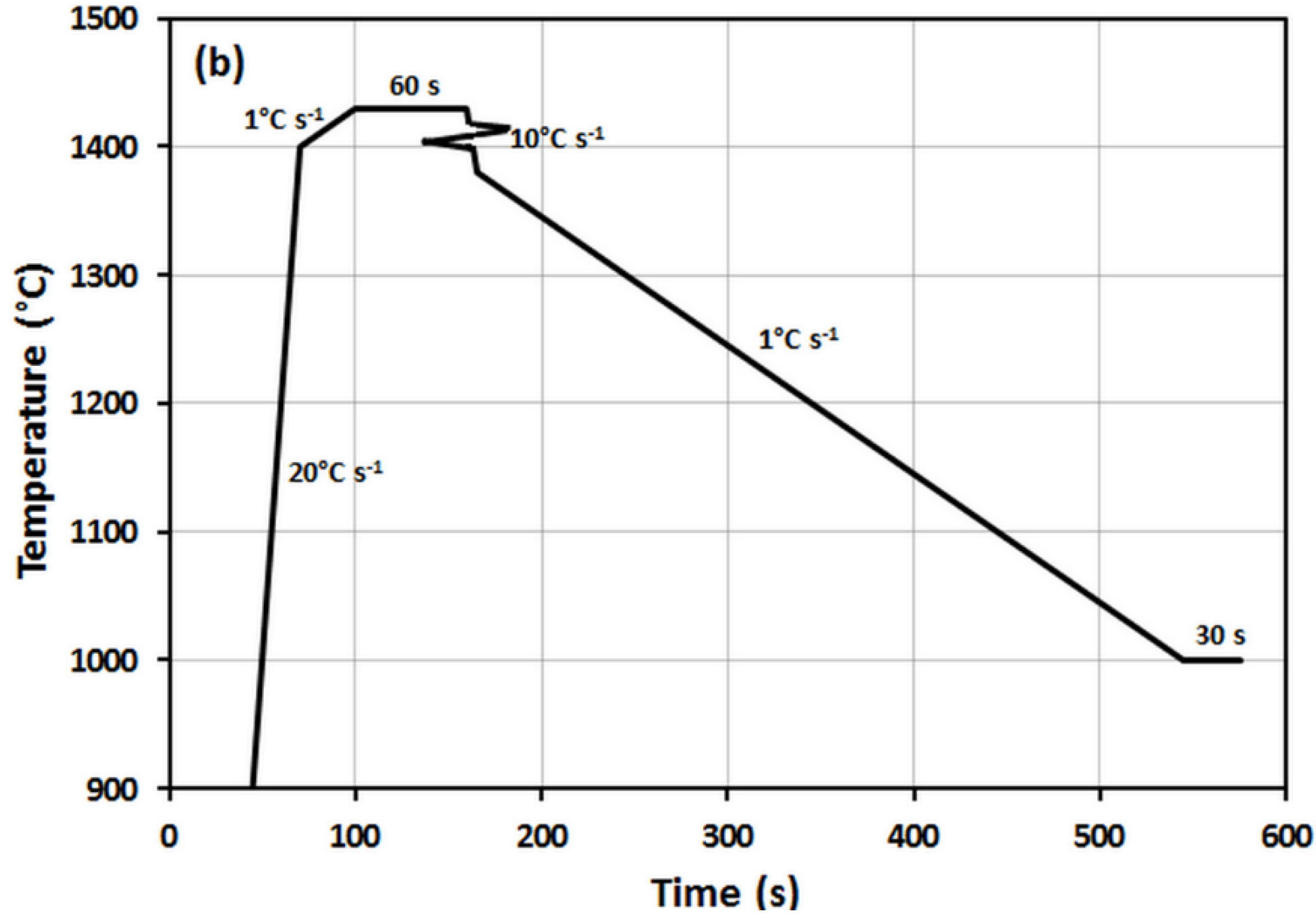
Specimens were first heated up to 1400 °C at a heating rate of 20 °C s
−1, then heated up to 1430 °C at a heating rate of 1 °C s
−1. This temperature value was detected as temperature whereby any shrinkage was not observed after solidification by performing a series of tests. Specimens are then heated slowly up to the temperature which melting occur and were held at this temperature for 60 s to heat the middle zone of specimens homogenously. A small amount of compressive deformation (2% to 10%) [
7,
20,
21] is axially applied onto the specimens during first solidification step through to 1380 °C to be able to eliminate the shrinkage. Approximately 2% compressive strain was applied to the specimens in these tests. Tensile tests are carried out after controlled cooling up to different tensile test temperatures at different cooling rates and were held at these temperatures for 30 s. Cooling rate can be selected within a wide range of between 0.05 and 20 °C s
−1 to simulate the continuous casting operation. Cooling rates were selected as 2, 1, 0.5 and 0.4 °C s
−1 in this study. Hot tensile tests were carried out according to the schedule given in
Table 1 after cooling at selected rates.
Table 1.
Hot tensile test schedule.
| Cooling Rate (°C s−1) | Test Temperature (°C) |
|---|
| 1200 | 1100 | 1050 | 1000 | 975 | 950 | 900 | 875 | 850 | 825 | 800 | 750 | 700 |
|---|
| 2.0 | √ | √ | √ | √ | | √ | √ | | √ | | √ | √ | √ |
| 1.0 | | √ | | √ | √ | √ | √ | √ | √ | √ | √ | | √ |
| 0.5 | | | | √ | | √ | √ | √ | √ | | | | |
| 0.4 | | | | | √ | √ | | | | | | | |
Percent reduction of area (RA %) is a good measure of cracking tendency [
3,
22]. Gleeble 3500 simulator can control thermal and mechanical cycles simultaneously by a computer and perform hot tensile tests at strain rates between 10
−5 s
−1 and 10
2 s
−1. Tensile strength (σ
max) and reduction of area (RA) which are measures of strength and ductility, respectively, are used as characteristic values of high temperature zone in literature [
3,
21]. Speed of hydraulic cross-head performing the tensile tests was 1 mm s
−1. Average strain rate was calculated assuming that the uniform deformation zone on specimen was at a length of 10 mm as in [
21] and the reduction of area was calculated by measuring the diameter on the fracture zone of the broken specimens [
23].
It was detected from the studies conducted by Gleeble simulators that temperature difference between surface and core of specimen increased by increasing temperature beginning from 1000 °C. This is due to existing thermal loss on the surface of specimen. This difference is about 50 °C at high temperatures [
21,
24]. Surface temperature of specimen was referred to test temperature in present study.
In addition to hot tensile tests, some fractographic examinations were carried out in scanning electron microscope. Specimens which were taken from the fractured zones of the parts were examined using Jeol scanning electron microscope (Jeol JSM 5600, Tokyo, Japan) equipped with Oxford X-ray microprobe (EDX) unit (Oxford, UK).
3. Results and Discussion
Hot ductility curves can be useful to get crack-free slabs during continuous casting in the steel mills. Reduction of area values are given as a function of test temperature in hot ductility curves. Embrittlement can occur if the reduction of area is lower than a certain value for a certain temperature range. This critical RA value for embrittlement is accepted as 60% in some studies [
25,
26,
27,
28].
Embrittlement was detected at three temperature zones in studies performed on the Gleeble simulator by Suzuki
et al. [
19,
21,
25]. Different studies on three zones are also available [
29,
30].
Embrittlement results from liquid phase existed along the dendrite interfaces in Zone I (Melting temperature—1200 °C). Ductility is not dependent on the strain rate in this zone.
Zone II (1200 to 900 °C) is stable austenite zone. Precipitation of finely distributed sulphides and phosphides at the austenite grain boundaries weakens the grain boundary strength. Slow cooling, holding at a certain temperature and low strain rate improves ductility. Amount and ratio of impurity elements are also important. Existence of phosphorus in the structure at this temperature zone also increases the embrittlement. As phosphorus content increases, the hot ductility around 1000 °C drops significantly [
25].
Zone III (900–600 °C) is austenite to ferrite transformation zone for low carbon steels. The most important property of this zone is the increase of embrittlement with decreasing strain rate. Embrittlement at this zone happens due to many factors: these are pro-eutectoid ferrite formation along austenite grain boundaries, intergranular precipitation, matrix hardening due to precipitation and grain boundary sliding.
Similar zones are mentioned in different studies for different types of materials and cooling rates [
3,
21,
31].
3.1. Steel Chemistry
Steel chemistry has great importance for hot ductility. C content is very important from the viewpoint of shrinkage upon solidification if the steel is especially a peritectic steel. Peritectic steels are generally defined as steels having carbon contents of 0.09%–0.17% C [
32], and the steel grade investigated in the current work is a peritectic steel. Peritectic steels are well known for their tendency to crack during continuous casting and it is difficult to cast this type of steels than the others. Peritectic steels show a high shrinkage upon solidification which leads to uneven heat removal from the solidifying steel shell resulting from the transformation from delta ferrite to austenite, hence irregular shell growth, creating stress raisers in the steel surface which in tension increases the susceptibility to cracking [
33]. The peritectic steels are also more prone to intergranular fracture as a result of large as-cast austenite grain size.
The region of low ductility is invariably associated with intergranular fracture, the fracture facets being either covered with fine dimples or micro voids, suggesting two distinct mechanisms depending on the temperature [
34]. Preferential deformation occurs in thin films of soft strain induced proeutectoid ferrite which is formed at the prior austenite grain boundaries on the low temperature side of the low ductility zone [
35]. The strain concentration initiates voids around the MnS inclusions located at the grain boundaries leading to intergranular failure via microvoid coalescence. Grain boundary failure is favored by the occurrence of grain boundary precipitation of second phases such as sulphides (MnS), oxysulfides or nitrides on the high temperature side of the low ductility zone. These act as stress concentrators and favor cavity and crack formation during deformation by grain boundary sliding.
Al, N and Ti contents are also important parameters in low C steels. In the presence of nitrogen, the aluminum precipitates as AlN. Increasing the amount of AlN also widens the ductility trough. When the N level increases, the amount of AlN precipitated increases. Therefore the N levels are aimed to be reduced to the levels of 0.003% [
11,
36].
Precipitation of fine AlN precipitates at the austenite grain boundaries leads to pinning of the boundaries and encourages void formation by grain boundary sliding in plain C–Mn steels [
37]. But there is some doubt in the studies searching for the detrimental influence of Al on hot ductility that the precipitation of AlN can occur in austenite with conventional Al levels at the relatively high cooling rates associated with continuous casting [
11]: Al has been found to have no influence on the hot ductility for samples solution treated and cooled to the test temperature for 0.02%–0.04% Al and 0.005% N. The Al levels have to be very high (≥0.7%) in order for AlN to be precipitated out and to have an influence on the hot ductility.
Marked differences in the kinetics of AlN precipitation observed in the literature may be ascribed to differences in Mn level. The [soluble Al] × [N] must exceed 1 × 10
−4 for any precipitation of AlN to occur in a steel with about 0.8%–1% Mn, so no AlN precipitation would be expected to be found in the high carbon steel even though the steel does contain a small amount of aluminum [
38]. Abushosha
et al. [
39] reports that the product of [Al] × [N] must approach 2 × 10
−4 for any precipitation to take place on cooling the steel after solution treatment at ~1300 °C for a cooling rate of 1 °C s
−1.
The investigated steel in this study has 0.060% Al and 0.0057% N; [Al] × [N] is 3.42 × 10⁻⁴. Since this material contains Ti which will form coarse TiN, the formation of fine AlN precipitates can be reduced. Sulphur levels should be kept as low as possible so as to reduce the volume fraction of MnS inclusions precipitated at the boundaries. The S level cannot be thought to be a problem in terms of cracking during continuous casting process. S content is low enough (Mn:S ratio is high enough (≈111)) and cannot form iron-rich sulphides which are detrimental to hot ductility.
3.2. The Effect of Cooling Rate on Hot Ductility
A series of melting-solidification-cooling operations were carried out to detect the effect of cooling rate on hot ductility. Hot tensile tests were performed at a strain rate of 0.1 s
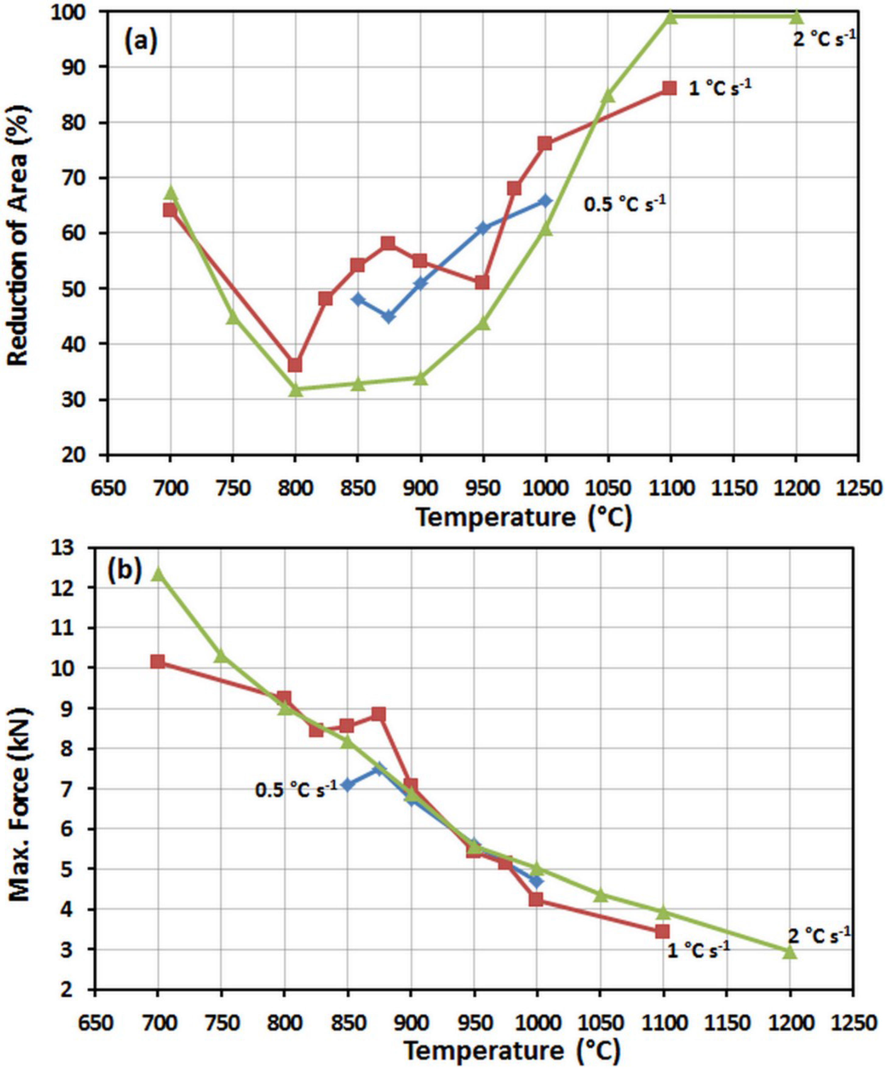
−1. Variation of reduction of area and maximum tensile force with temperature is given in
Figure 1a, b respectively depending on the different cooling rates (2, 1 and 0.5 °C s
−1).
Figure 1.
(a) Variation of reduction of area (hot ductility) with temperature. (b) Variation of maximum force with temperature (έ = 0.1 s−1).
There is a wide trough (brittle zone) between 1000 and 725 °C at a cooling rate of 2 °C s
−1 as can be seen from
Figure 1a. RA decreases to a minimum value at 800 °C throughout the cooling from melting point to 700 °C. In a study analyzing the hot ductility of steel using a micro-macro model approach, it was found that the ferrite networks caused a large drop in ductility explaining the lower ductility seen in the two-phase region in the steel material [
40]: a decrease in temperature from 870 °C to 800 °C causes an increase in RA from 7% to 31%. Jiang
et al. found a tendency for a low alloy steel in the hot ductility curve [
5,
41] that reduction of area decreased to a minimum value at about 850 °C for both doped with P and undoped steels (cooling rate is 5 °C s
−1).
Rezaeian
et al. [
7] mentions a deep trough from 700 to 1000 °C, with the exception of 900 °C, in hot ductility for two kinds of steels (V steel: 0.17% C, 0.91% Mn, 0.023% V; and C steel: 0.185% C, 1.02% Mn). It is reported that 10% compressive predeformation at very high temperature (
i.e., 1300 to 1400 °C) can improve the hot ductility of both peritectic steels at temperatures above 800 °C and this ductility improvement corresponds to a reduction of segregation at grain boundaries and also grain refinement as a result of grain boundary migration due to recrystallization. In another study [
42], it is reported that the ductility trough of ultra-high purity iron alloyed by selected amount of Al, N and S extends from 850 °C to 1150 °C.
It is seen from
Figure 1a that RA decreases to 51% at 950 °C upon cooling for a cooling rate of 1 °C s
−1, and then there is a zone at 875 °C which ductility improves and RA decreases to a minimum at 800 °C as the one in the cooling rate of 2 °C s
−1. Ductility again improves at temperatures less than 800 °C. A slight increase in RA in the low temperature brittle zone for Ti–V bearing microalloyed steel was also reported in the temperature ranging from 800 to 750 °C due to the presence of thin film of ferrite at austenite grain boundaries [
35]. Although sufficient tests were not conducted in a wide temperature range for cooling rate of 0.5 °C s
−1, it was seen that RA values decreased to below 60% at 950 °C and reached a minimum at 875 °C; then a small amount of improvement was seen at temperatures lower than this level (
Figure 1a).
It is observed that maximum force values obtained from hot tensile tests increase with decreasing test temperatures. Erisir
et al. [
18] found a similar tendency at a strain rate of 1 s
−1 for both RA-temperature and maximum force-temperature curves in a nickel free austenitic steel with high nitrogen content: hot ductility curve indicated a decrease in the reduction of area from 65% to 10% with decreasing temperatures between 900 °C and 1150 °C and maximum force curve indicated a decrease with increasing temperature. Forces obtained from the tests at different cooling rates are comparable in the present work (
Figure 1b).
3.3. Effect of Strain Rate on Ductility
In addition to tests carried out at a strain rate of 0.1 s
−1 at 1000 °C (cooling rate: 1 °C s
−1), hot tensile tests were also carried out at strain rates of 0.01, 0.05 and 1 s
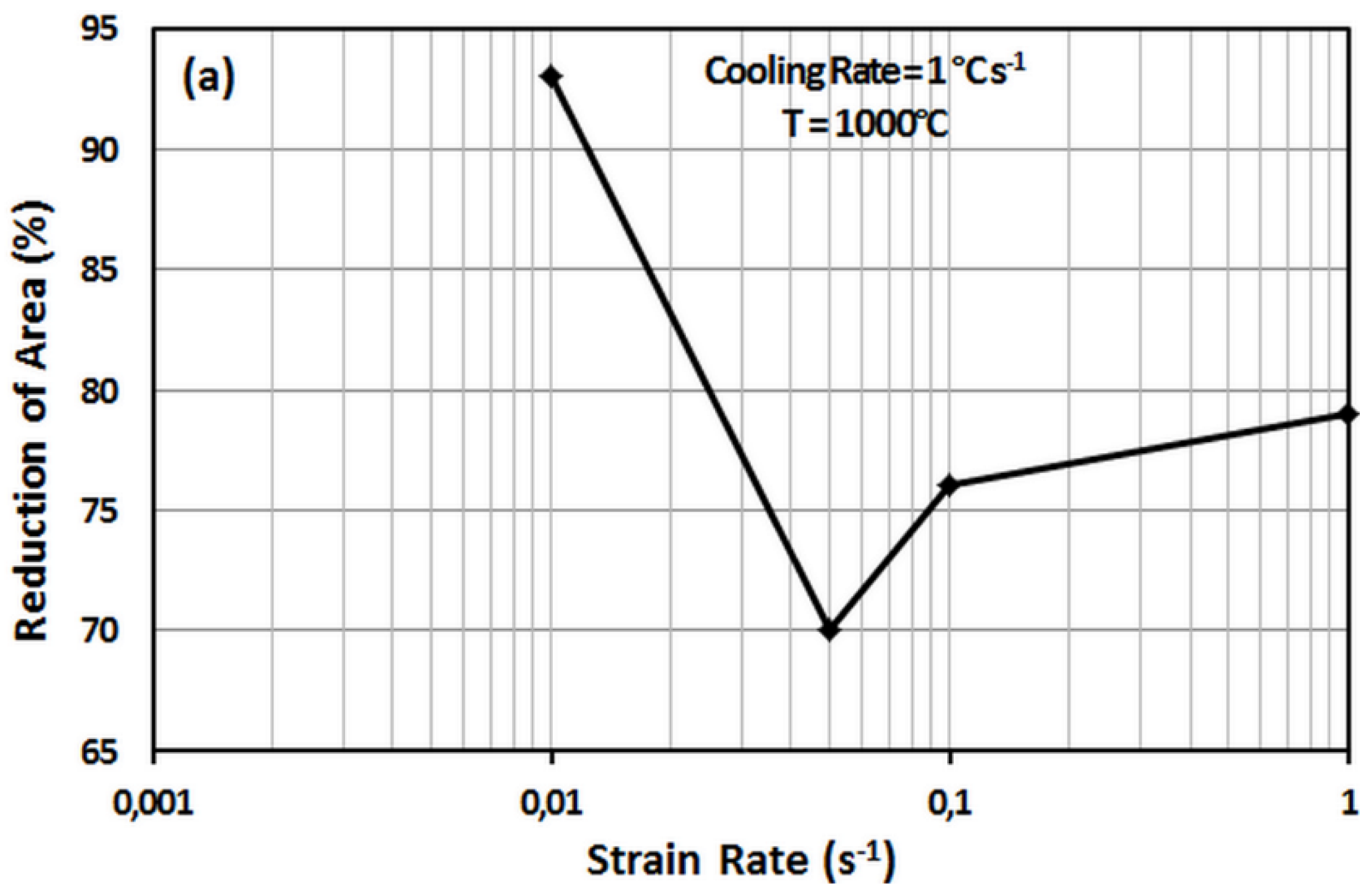
−1 to investigate the effect of strain rate on ductility. Variation of RA with strain rate is given in
Figure 2a and applied thermal cycle is given in
Figure 2b.
Figure 2.
(a) Effect of strain rate on ductility. (b) Applied thermal cycle.
RA value first decreases with increasing strain rate. Small amount of increase at 1000 °C is observed in RA values after reaching a minimum at 70% at a strain rate of 0.05 s
−1. Similar tendency but different minimum RA values at strain rates ranging from 10
−3 to 10
1 s
−1 are seen at 1000 °C for various materials: RA values decrease from 80% at ≈10
−3 s
−1 to ≈15% at ≈0.5 s
−1 in a plain C steel (0.12% C) [
21] and from 80% to ≈20% at ≈0.5 s
−1 in a 0.7% C steel at 1000 °C [
25]; then a small increase is observed.
3.4. Fractograpy
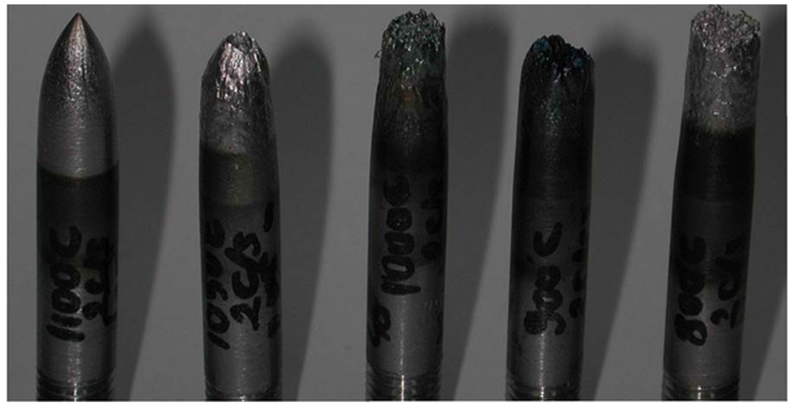
Specimens which were broken in the hot tensile tests performed at 1100, 1050, 1000, 900 and 800 °C after cooling at a rate of 2 °C s
−1 are shown in
Figure 3. Type of fracture is observed to be ductile at 1100 and 1050 °C; semi-ductile at 1000 °C and brittle at 900 and 800 °C.
Figure 3.
Some of the broken pieces of specimens after hot tensile tests.
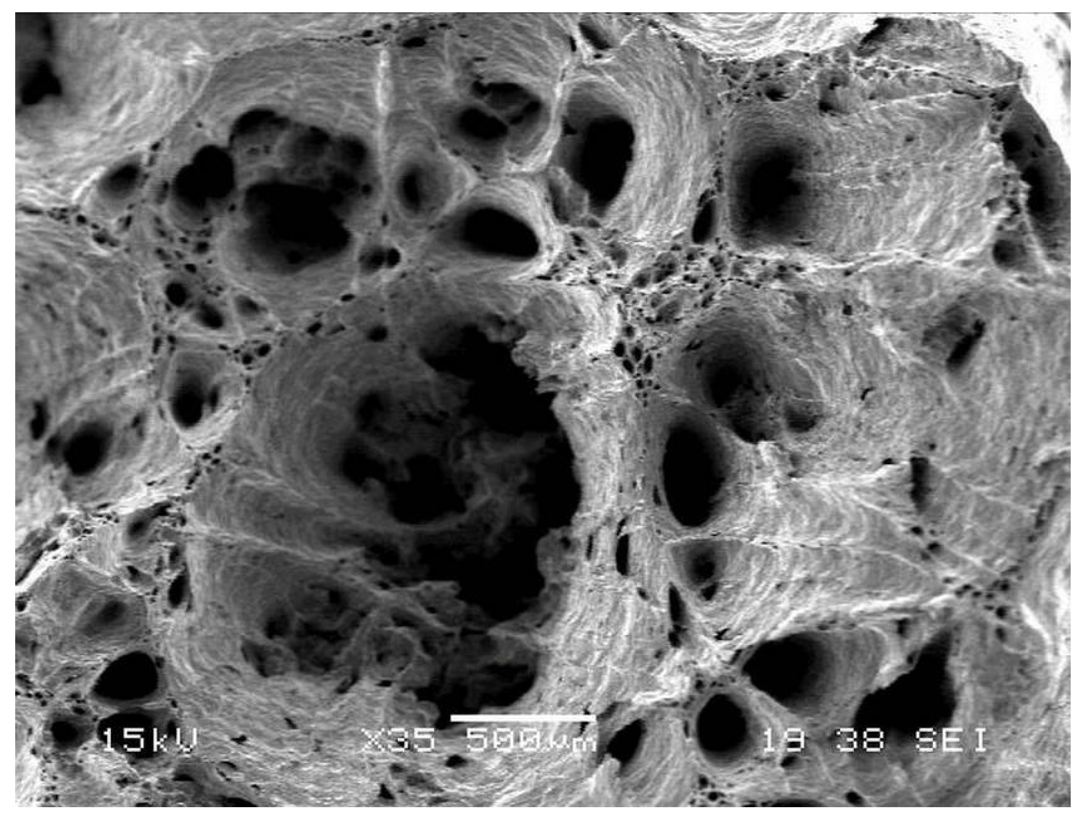
SEM investigations were carried out on some of the specimens to confirm the nature of fracture. SEM images of fracture surfaces are shown in
Figure 4 ,
Figure 5,
Figure 6 and
Figure 7 for specimens tested at different temperatures upon cooling at a rate of 2 °C s
−1. Strain rate during the tests was 0.1 s
−1.
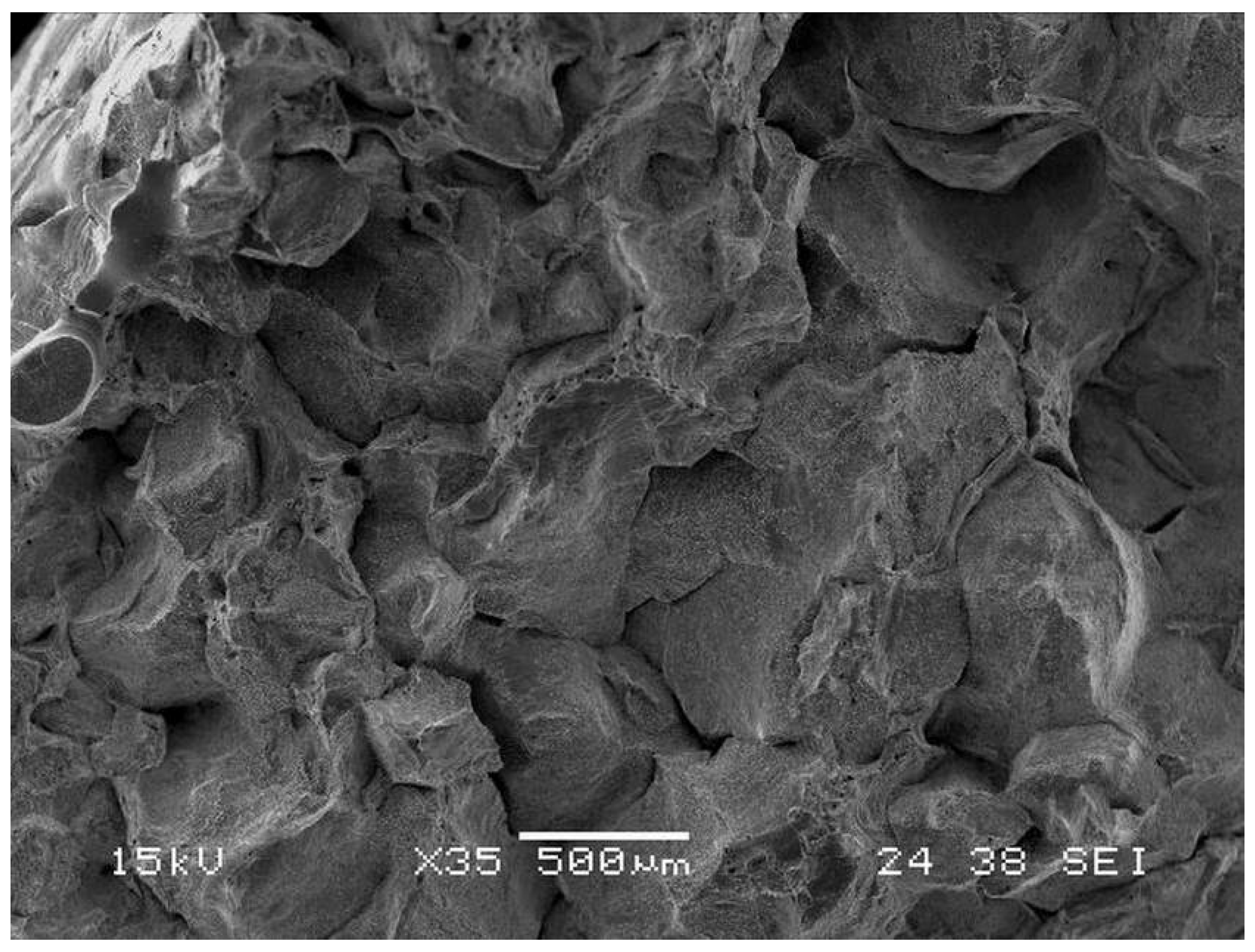
Figure 4.
SEM image of fracture surface for the specimen tested at 1100 °C.
Figure 5.
SEM image of fracture surface for the specimen tested at 1050 °C.
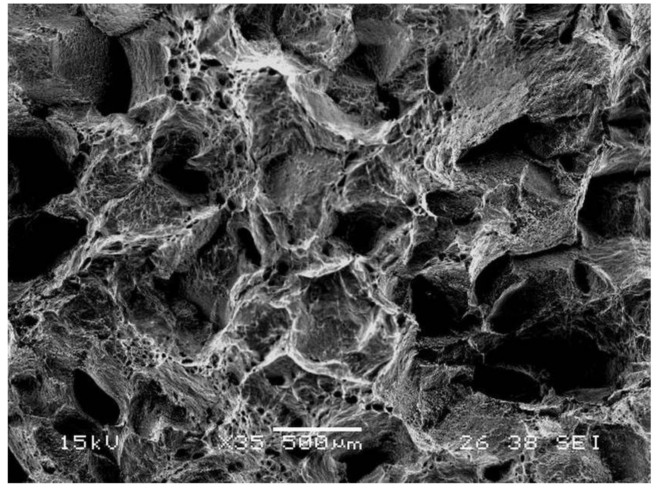
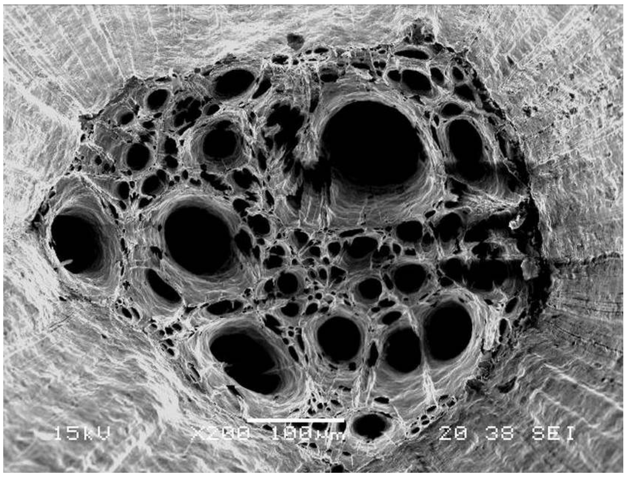
Figure 6.
SEM image of fracture surface for the specimen tested at 1000 °C.
Figure 7.
SEM image of fracture surface for the specimen tested at 800 °C.
A dimple fracture was observed at 1100 °C and this is clearly visible in
Figure 4: RA has a very high value (99%). Dimples are again dominant at 1050 °C (
Figure 5) and RA is still high: 85%. At 1000 °C, grain boundary facets show dimples in many areas indicating the traces of ductility (RA = 61%) as seen in
Figure 6. Fracture mode is intergranular and small dimples on the grain facets can be noticed at 800 °C (
Figure 7), and RA is 32% which is lower than the values at higher temperatures.
3.5. Continuous Casting Process Map
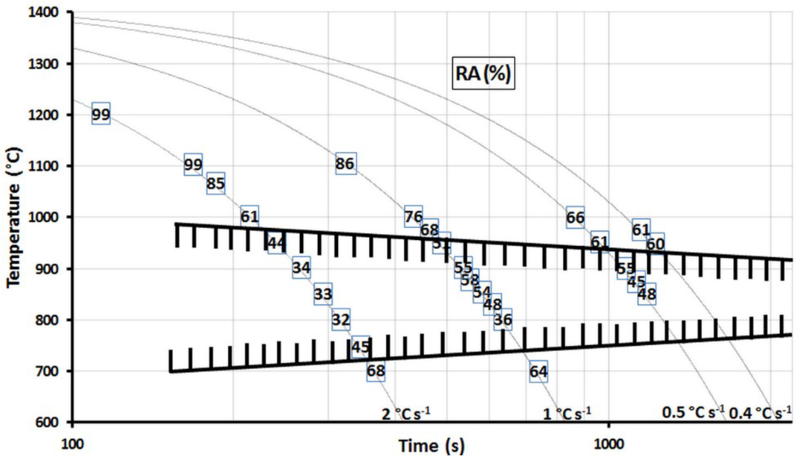
Continuous casting process (time-temperature-ductility) map was obtained in this study. RA % values obtained from the trials performed at different temperatures and cooling rates were superimposed on time-temperature diagram and the map for the investigated steel is shown in
Figure 8. There is a zone corresponding to a lack of hot ductility which RA values are under 60% between ≈1000 and 725 °C. This zone gets slightly narrow as the cooling rate decreases. Optimum cooling curve can be adjusted to get crack-free slabs in the continuous casting process of this steel grade by considering the map in
Figure 8. Transverse surface cracks may develop mainly during the unbending process of the strand at the exit of the continuous casting machines. These cracks should be avoided by straightening the cast slabs outside the temperature range between 1000 and 725 °C. Straightening of the strand should be completed up to 1000 °C during cooling from the melt to avoid surface problems for the steel P245NB. One of the measures Wu
et al. also mention in their research [
28] for preventing the slab fractures is the avoidance of the ductility trough. Although there is little scope for alterations in casting speed or caster geometry because of the restraints associated with plant design, increasing the strain rate during straightening could improve the hot ductility and a small increase in casting speed can significantly reduce transverse cracking if the straightening procedure is executed in the high ductility high temperature region [
11].
Figure 8.
Continuous casting process (time-temperature-ductility) map of a peritectic steel for welded gas cylinders (έ = 0.1 s−1; shaded area shows poor ductility zone and figures on the cooling routes represent RA values).
4. Conclusions
Casting slab is subjected to various thermo-mechanical stresses and deformation during straightening between casting mold of continuous casting machine and exit table. Typical thermo-mechanical stresses result from shrinkages or expansions due to water cooling, misalignment of guide rolls at secondary cooling zone, bulging due to hydrostatic pressure and mechanical stresses at straightening points.
Surface fractures occur during continuous casting operation if critical stress is exceeded. Percentage reduction of area is a good measure of cracking tendency and 60% is accepted as the critical RA level not to be encountered with cracks. Cracking susceptibility increases with decreasing RA values. There is a brittle zone between 1000 and 725 °C at a cooling rate of 2 °C s−1. RA decreases to a minimum value at 800 °C. This brittle zone gets slightly narrow as the cooling rate decreases.
RA first decreases with increasing strain rate. After reaching a minimum RA value at 70% at a strain rate of 5 × 10⁻² s−1 at 1000 °C, small amount of increment is observed in RA values.
Type of fracture is ductile at 1100 and 1050 °C; semi-ductile at 1000 °C, and brittle at 800 °C for the steel P245NB. Totally dimple area is observed at 1100 °C and RA is very high. Dimples are again dominant at 1050 °C. Grain boundary facets show dimples in many areas indicating the traces of ductility at 1000 °C. Small dimples on the grain facets are noticeable at 800 °C.
Considering the temperature zone with low ductility for different cooling rates should be useful for crack-free slab production in the continuous casting process of this steel grade. Transverse surface cracks may develop mainly during the unbending process of the strand at the exit of the continuous casting machines. It should be attempted to straighten the continuously cast strands outside the temperature range of between 1000 and 725 °C. Completion of straightening of the strand up to 1000 °C on the way of cooling from the melt will be effective to avoid transverse surface cracking problems for the steel P245NB. Increasing the casting speed and strain rate during straightening can be useful for this purpose.


