
Influence of Particulate Reinforcement and Equal-Channel Angular Pressing on Fatigue Crack Growth of an Aluminum Alloy


Abstract
:1. Introduction
2. Experimental Section
2.1. Material

| Element | Al | Cu | Mn | Mg | Fe | Si | Zn |
|---|---|---|---|---|---|---|---|
| wt % | >94.1 | 4.1 | 0.8 | 0.6 | 0.2 | 0.1 | traces |
2.2. Methods of Mechanical Testing and Electron Microscopy
3. Results and Discussion
3.1. Tensile Tests
| Material | Yield Strength in MPa | Ultimate Tensile Strength in MPa | Uniform Elongation in % | Elongation to Fracture in % |
|---|---|---|---|---|
| Al 2017 unreinforced | 252 | 435 | 20 | 29 |
| Al 2017 unreinforced after 1 ECAP pass | 487 | 566 | 11 | 17 |
| Al 2017 with 5 vol % Al2O3 | 328 | 511 | 11 | 13 |
| Al 2017 with 5 vol % Al2O3 after 1 ECAP pass | 509 | 580 | 5 | 8 |
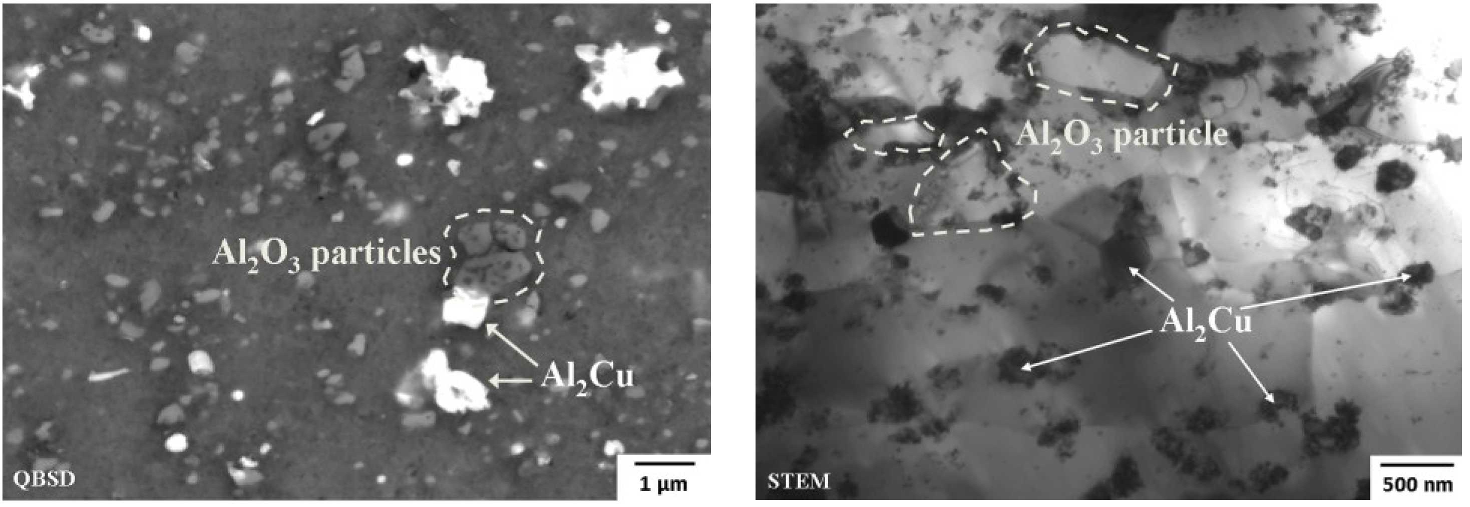
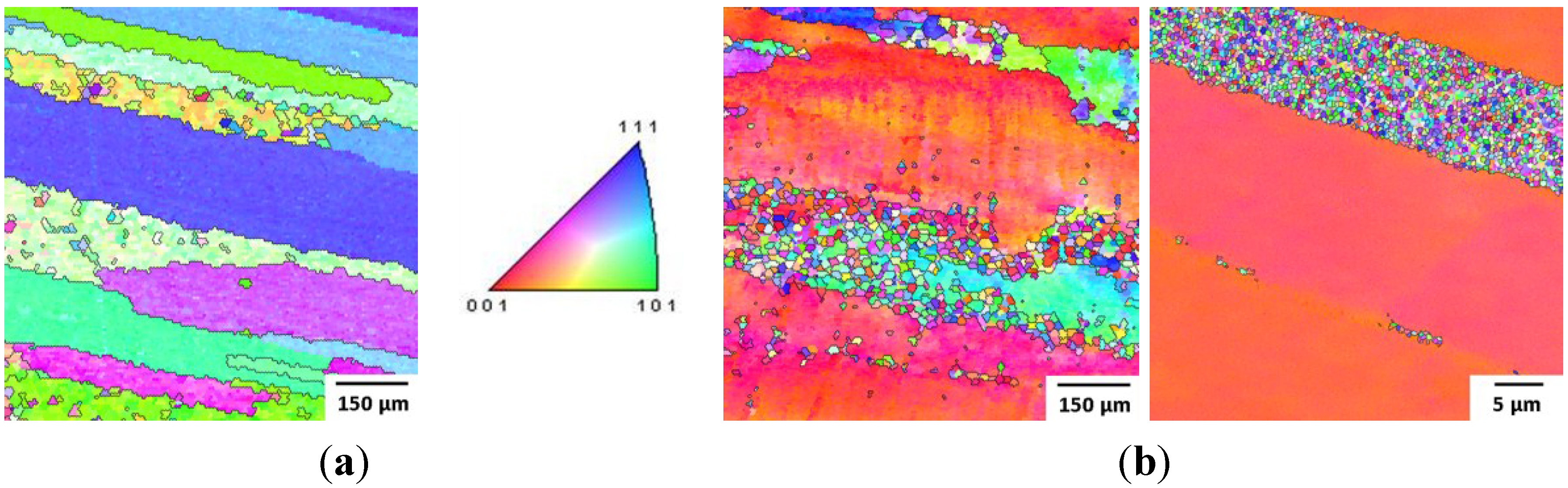
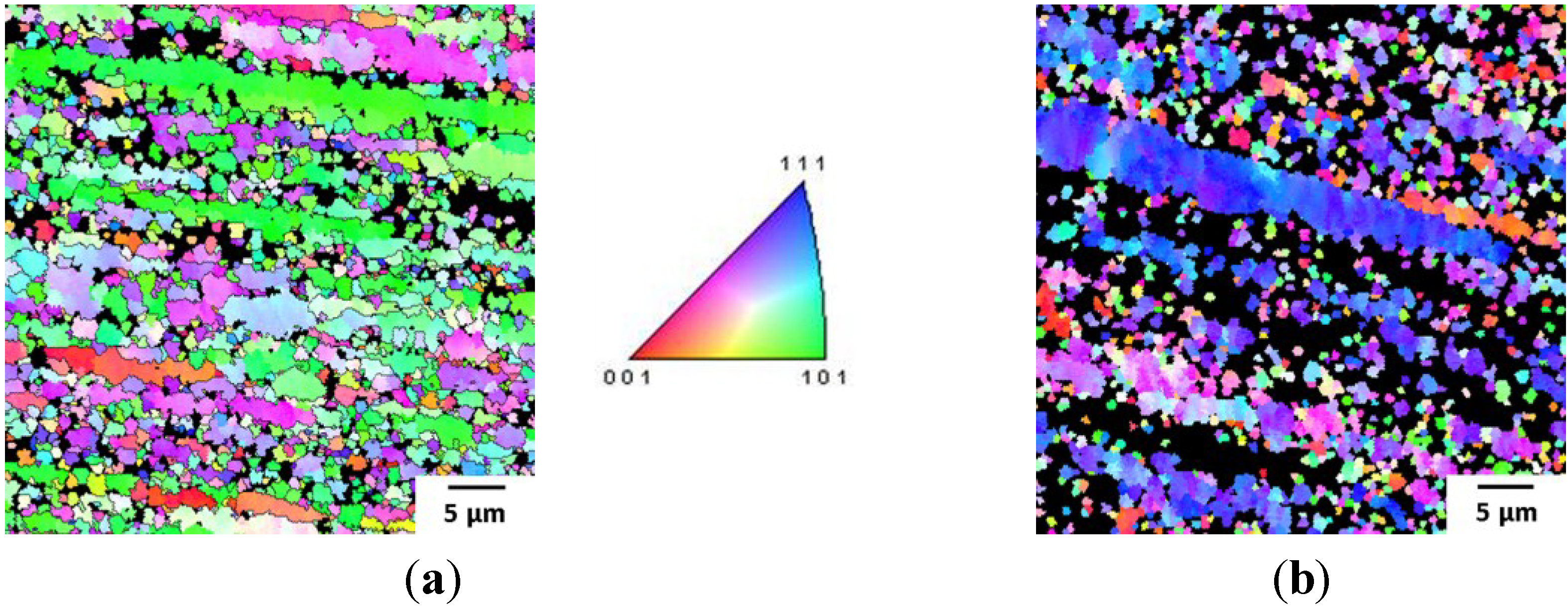
3.2. Microstructure

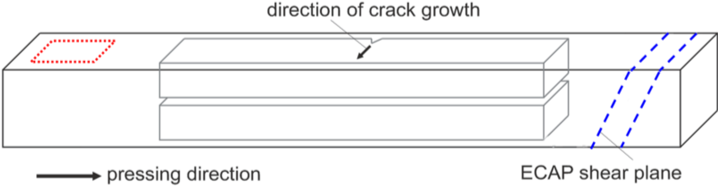
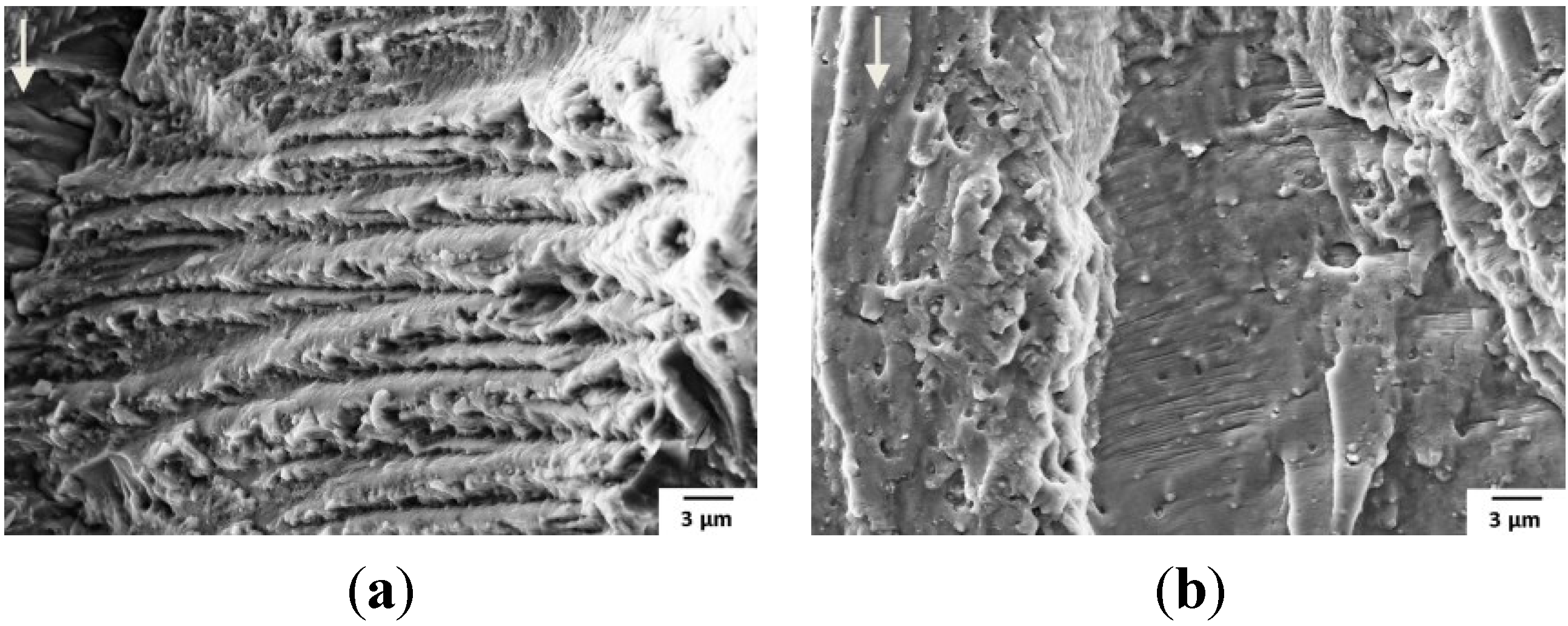
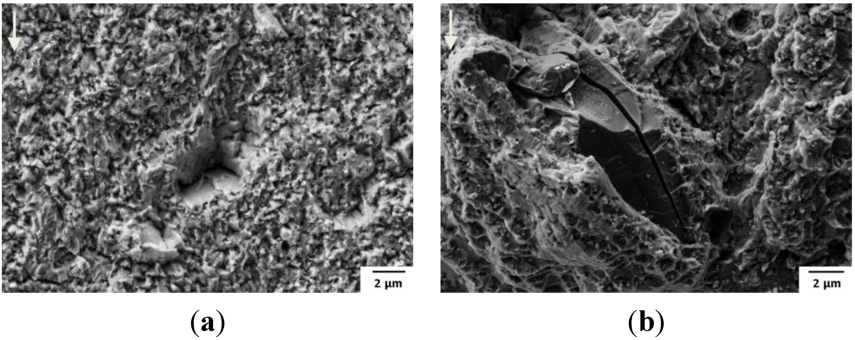
3.3. Fatigue Crack Surface Analysis
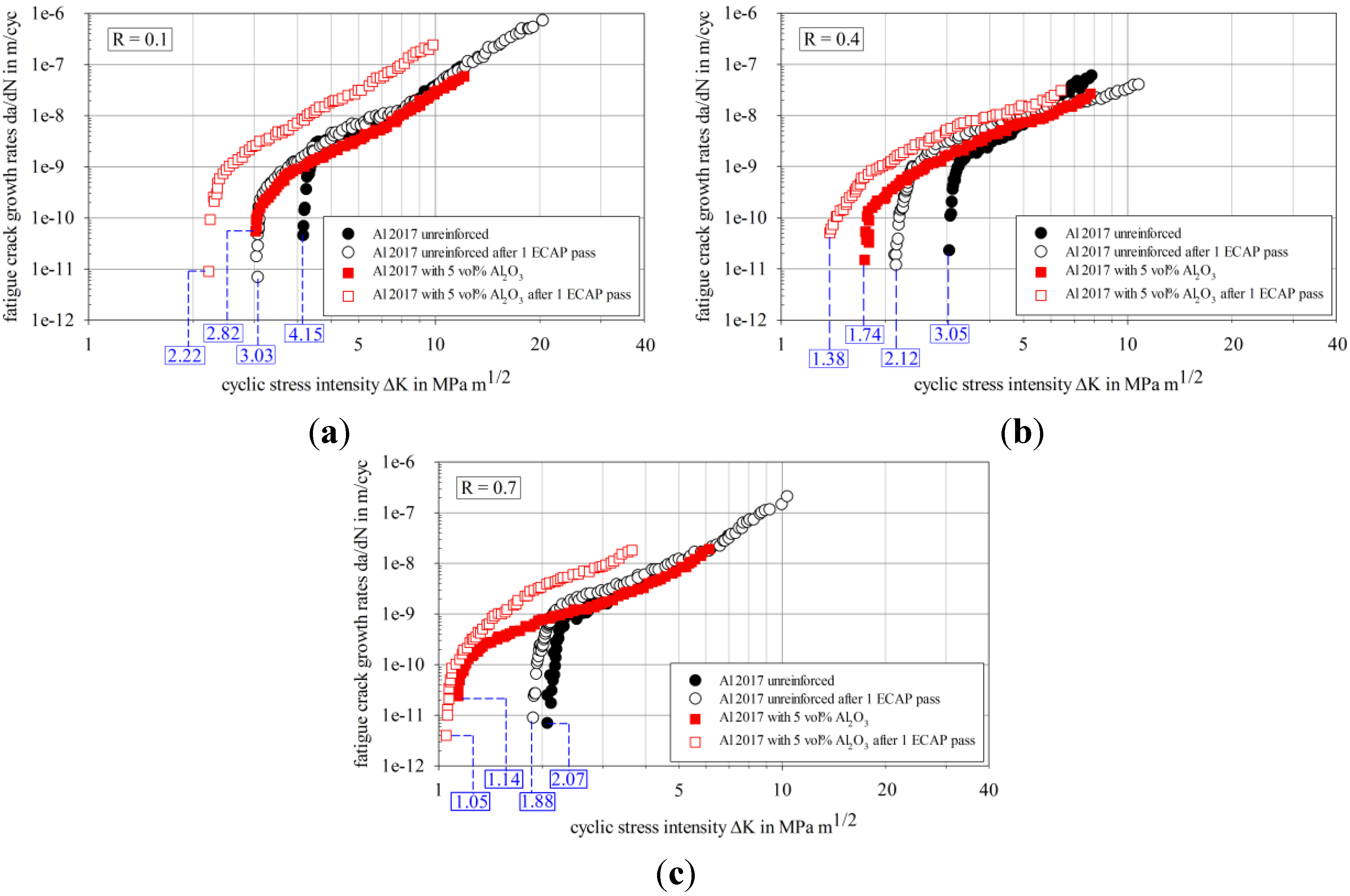
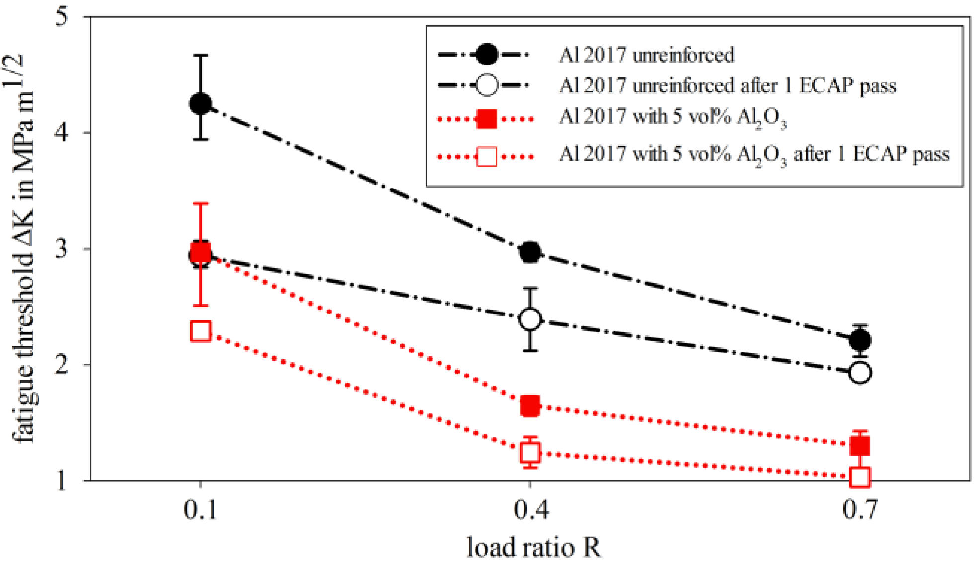
3.4. Fatigue Crack Propagation

4. Conclusions
- (1)
- One ECAP pass of the unreinforced material results in an inhomogeneous microstructure with shear bands. These shear bands are characterized by a considerably reduced grain size. In the surrounding areas, the grains are strongly elongated, but not refined. The grain size of the reinforced material is significantly lower, as compared to the unreinforced. Additional ECAP does not lead to a significant grain refinement, here.
- (2)
- The yield strength of both materials, unreinforced and reinforced, is increased by one pass of ECAP. However, the strain hardening effect of ECAP is more pronounced in the unreinforced material.
- (3)
- Due to the major grain size of the unreinforced matrix material, the high amount of crack deflection and roughness-induced crack closure lead to a tortuous crack path and therefore to minor crack propagation rates. The grain refinement through one ECAP pass reduces these effects. Supposedly because crack propagation occurred in the finer-grained shear bands, the fatigue thresholds and their dependency on the load ratio are diminished for the unreinforced material after ECAP.
- (4)
- For the reinforced material, the fatigue thresholds are drastically reduced due to the significantly smaller grain size of these conditions. Despite their small grain size, the reinforced materials exhibit a strong dependency on the load ratio. Here, the interaction between the aluminum matrix and the interface is perceived as crucial: the susceptibility to cracking of the particle-matrix-interface is strongly increased at higher load ratios. This leads to a “particle-failure-induced” load ratio dependency.
Acknowledgments
Author Contributions
Conflicts of Interest
References
- Chawla, N.; Shen, Y.L. Mechanical behavior of particle reinforced metal matrix composites. Adv. Eng. Mater. 2001, 3, 357–370. [Google Scholar] [CrossRef]
- Mani, B.; Paydar, M.H. Application of forward extrusion-equal channel angular pressing (FE-ECAP) in fabrication of aluminum metal matrix composites. J. Alloys Compd. 2010, 492, 116–121. [Google Scholar] [CrossRef]
- Tan, M.J.; Zhang, X. Powder metal matrix composites: Selection and Processing. Mater. Sci. Eng. A 1998, 244, 80–85. [Google Scholar] [CrossRef]
- Ramu, G.; Bauri, R. Effect of equal channel angular pressing (ECAP) on microstructure and properties of Al-SiCp composites. Mater. Des. 2009, 30, 3554–3559. [Google Scholar] [CrossRef]
- Sabirov, I.; Kolednik, O.; Valiev, R.Z.; Pippan, R. Equal channel angular pressing of metal matrix composites: Effect on particle distribution and fracture toughness. Acta Mater. 2005, 53, 4919–4930. [Google Scholar] [CrossRef]
- Valiev, R.Z.; Islamgaliev, R.K.; Kuzmina, N.F.; Li, Y.; Langdon, T.G. Strengthening and grain refinement in an Al-6061 metal matrix composite through intense plastic straining. Scr. Mater. 1999, 40, 117–122. [Google Scholar] [CrossRef]
- Muñoz-Morris, M.A.; Calderón, N.; Guitierrez-Urrutia, I.; Morris, D.G. Matrix grain refinement in Al-TiAl composites by severe plastic deformation: Influence of particle size and processing route. Mater. Sci. Eng. A 2006, 425, 131–137. [Google Scholar] [CrossRef] [Green Version]
- Segal, V.M.; Reznikov, V.I.; Drobyshevskiy, A.E.; Kopylov, V.I. Plastic working of metals by simple shear (Russian translation). Russ. Metall. 1981, 1, 99–105. [Google Scholar]
- Valiev, R.Z.; Langdon, T.G. Principles of equal-channel pressing as a processing tool for grain refinement. Prog. Mater. Sci. 2006, 51, 881–981. [Google Scholar] [CrossRef]
- Furukawa, M.; Horita, Z.; Langdon, T.G. Developing ultrafine grain sizes using severe plastic deformation. Adv. Eng. Mater. 2001, 3, 121–125. [Google Scholar] [CrossRef]
- Pao, P.S.; Jones, H.N.; Cheng, S.F.; Feng, C.R. Fatigue crack propagation in ultrafine grained Al-Mg alloy. Int. J. Fatigue 2005, 27, 1164–1169. [Google Scholar] [CrossRef]
- Hübner, P.; Kiessling, R.; Biermann, H.; Hinkel, T.; Jungnickel, W.; Kawalla, R.; Höppel, H.-W.; May, J. Static and cyclic crack growth behavior of ultrafine-grained Al produced by different severe plastic deformation methods. Metall. Mater. Trans. A 2007, 38, 1926–1933. [Google Scholar] [CrossRef]
- Vinogradov, A. Fatigue limit and crack growth in ultra-fine grain metals produced by severe plastic deformation. J. Mater. Sci. 2007, 42, 1797–1808. [Google Scholar] [CrossRef]
- Cavaliere, P. Fatigue properties and crack behavior of ultra-fine and nanocrystalline pure metals. Int. J. Fatigue 2009, 31, 1476–1489. [Google Scholar] [CrossRef]
- Estrin, Y.; Vinogradov, A. Fatigue behaviour of light alloys with ultrafine grain structure produced by severe plastic deformation: An overview. Int. J. Fatigue 2010, 32, 898–907. [Google Scholar] [CrossRef]
- Meyer, L.W.; Sommer, K.; Halle, T.; Hockauf, M. Crack growth in ultrafine-grained AA6063 produced by equal-channel angular pressing. J. Mater. Sci. 2008, 43, 7426–7431. [Google Scholar] [CrossRef]
- Avtokratova, E.V.; Sitdikov, O.S.; Kaibyshev, R.O.; Watanabe, Y. Behavior of a submicrocrystalline aluminum alloy 1570 under conditions of cyclic loading. Phys. Met. Metallogr. 2009, 107, 291–297. [Google Scholar] [CrossRef]
- Hockauf, K.; Wagner, M.F.-X.; Halle, T.; Niendorf, T.; Hockauf, M.; Lampke, T. Influence of precipitates on low-cycle fatigue and crack growth behavior in an ultrafine-grained aluminum alloy. Acta Mater. 2014, 80, 250–263. [Google Scholar] [CrossRef]
- Chen, Z.Z.; Tokaji, K. Effects of particle size on fatigue crack initiation and small crack growth in SiC particulate-reinforced aluminum alloy composites. Mater. Lett. 2004, 58, 2314–2321. [Google Scholar] [CrossRef]
- Levin, M.; Karlsson, B. Influence of SiC particle distribution and prestraining on fatigue crack growth rates in aluminum AA 6061-SiC composite material. Mater. Sci. Technol. 1991, 7, 596–607. [Google Scholar] [CrossRef]
- Mason, J.J.; Ritchie, R.O. Fatigue crack growth resistance in SiC particulate and whisker reinforced P/M 2124 aluminum matrix composites. Mater. Sci. Eng. A 1997, 231, 170–182. [Google Scholar] [CrossRef]
- Llorca, J. Fatigue of particle- and whisker-reinforced metal-matrix composites. Prog. Mater. Sci. 2002, 47, 283–353. [Google Scholar] [CrossRef]
- Oh, K.H.; Han, K.S. Short-fiber/ particle hybrid reinforcement: Effects on fracture toughness and fatigue crack growth of metal matrix composites. Comput. Sci. Technol. 2007, 67, 1719–1726. [Google Scholar] [CrossRef]
- Chawla, N.; Ganesh, V.V. Fatigue crack growth of SiC particle reinforced metal matrix composites. Int. J. Fatigue 2010, 32, 856–863. [Google Scholar] [CrossRef]
- Huang, M.; Li, Z. Size effects on stress concentration induced by a prolate ellipsoidal particle and void nucleation mechanism. Int. J. Plast. 2005, 21, 1568–1590. [Google Scholar] [CrossRef]
- Xue, Z.; Huang, Y.; Li, M. Particle size effect in metallic materials: A study by the theory of mechanism-based strain gradient plasticity. Acta Mater. 2002, 50, 149–160. [Google Scholar] [CrossRef]
- Slipenyuk, A.; Kuprin, V.; Milman, Y.; Goncharuk, V.; Eckert, J. Properties of P/M processed particle reinforced metal matrix composites specified by the reinforcement concentration and matrix-to-reinforcement particle size ratio. Acta Mater. 2006, 54, 157–166. [Google Scholar] [CrossRef]
- Wagner, S.; Siebeck, S.; Hockauf, M.; Nestler, D.; Podlesak, H.; Wielage, B.; Wagner, M.F.X. Effect of SiC-reinforcement and equal-channel angular pressing on microstructure and mechanical properties of AA2017. Adv. Eng. Mater. 2012, 14, 388–393. [Google Scholar] [CrossRef]
- Iwahashi, Y.; Wang, J.T.; Horita, Z.; Nemoto, M.; Langdon, T.G. Principle of equal-channel angular pressing for the processing of ultra-fine grained materials. Scr. Mater. 1996, 35, 143–146. [Google Scholar] [CrossRef]
- Kim, J.K.; Jeong, H.G.; Hong, S.I.; Kim, Y.S.; Kim, W.J. Effect of aging treatment on heavily deformed microstructure of a 6061 aluminum alloy after equal channel angular pressing. Scr. Mater. 2014, 45, 901–907. [Google Scholar] [CrossRef]
- Hockauf, M.; Meyer, L.W.; Zillmann, B.; Hietschold, M.; Schulze, S.; Krüger, L. Simultaneous improvement of strength and ductility of Al-Mg-Si alloys by combining equal-channel angular extrusion with subsequent high-temperature short-time aging. Mater. Sci. Eng. A 2009, 503, 167–171. [Google Scholar] [CrossRef]
- ASTM E399-12e3. In Standard Test Method for Linear-elastic Plane-Strain Fracture Toughness KIc of Metallic Materials; American Society for Testing and Materials: West Conshohocken, PA, USA, 1970.
- Hockauf, M.; Schönherr, R.; Wagner, S.; Meyer, L.W.; Podlesak, H.; Mücklich, S.; Wielage, B.; Krüger, L.; Hahn, F.; Weber, D. Equal-channel angular pressing of medium- to high-strength precipitation hardening aluminium wrought alloys. Mat.-Wiss. Werkstofftech. 2009, 40, 540–550. [Google Scholar] [CrossRef]
- Shang, J.K.; Ritchie, R.O. On the particle-size dependence of fatigue-crack propagation thresholds in SiC-particulate-reinforced aluminium alloy composites: Role of crack closure and crack trapping. Acta Metall. 1989, 37, 2267–2278. [Google Scholar] [CrossRef]
- Hockauf, K.; Halle, T.; Hockauf, M.; Wagner, M.F.-X.; Lampke, T. Near-threshold fatigue crack propagation in an ECAP-processed ultrafine-grained aluminium alloy. Mater. Sci. Forum 2011, 667–669, 873–878. [Google Scholar]
- Shang, J.K.; Yu, W.; Ritchie, R.O. Role of silicon carbide particles in fatigue crack growth in SiC-particulate-reinforced aluminum alloy composites. Mater. Sci. Eng. A 1988, 102, 181–192. [Google Scholar] [CrossRef]
© 2015 by the authors; licensee MDPI, Basel, Switzerland. This article is an open access article distributed under the terms and conditions of the Creative Commons Attribution license (http://creativecommons.org/licenses/by/4.0/).
Share and Cite
Köhler, L.; Hockauf, K.; Lampke, T. Influence of Particulate Reinforcement and Equal-Channel Angular Pressing on Fatigue Crack Growth of an Aluminum Alloy. Metals 2015, 5, 790-801. https://doi.org/10.3390/met5020790
Köhler L, Hockauf K, Lampke T. Influence of Particulate Reinforcement and Equal-Channel Angular Pressing on Fatigue Crack Growth of an Aluminum Alloy. Metals. 2015; 5(2):790-801. https://doi.org/10.3390/met5020790
Chicago/Turabian StyleKöhler, Lisa, Kristin Hockauf, and Thomas Lampke. 2015. "Influence of Particulate Reinforcement and Equal-Channel Angular Pressing on Fatigue Crack Growth of an Aluminum Alloy" Metals 5, no. 2: 790-801. https://doi.org/10.3390/met5020790