
Phytic-Acid-Modified Copper Foil as a Current Collector for Lithium-Ion Batteries
1
School of Materials Science and Engineering, State Key Laboratory of Silicon Materials, Zhejiang University, Hangzhou 310027, China
2
Key Laboratory of Advanced Materials and Applications for Batteries of Zhejiang Province, Hangzhou 310027, China
*
Author to whom correspondence should be addressed.
Metals 2024, 14(2), 247; https://doi.org/10.3390/met14020247
Submission received: 18 January 2024
/
Revised: 15 February 2024
/
Accepted: 16 February 2024
/
Published: 18 February 2024
(This article belongs to the Special Issue Recent Advances in Corrosion and Protection of Metallic Materials)
Abstract
:Electrolytic copper foil is ideal for use in the anode current collectors of lithium-ion batteries (LIBs) because of its abundant reserves, good electrical conductivity, and soft texture. However, electrolytic copper foil is prone to corrosion in electrolytes and weak bonding to the anode substance. Surface modification of copper foil is considered an effective method of improving the overall electrochemical performance of LIBs. In this study, a 5 nm thickness phytic acid (PA)-based film is constructed on electrolytic copper foil using a fast electrodeposition process (about 10 s). PA-treated copper foil (PA-Cu) displays an improved corrosion resistance in electrolytes because of a strong complexation between the PA and copper. It is found that PA-treated copper foil also bonds better with graphite particles compared with pristine copper foil. LIBs with PA-Cu foils as their current collectors exhibit enhanced cycling stability, improved capacity retention, and superior rate performance at both low and high current densities. Our study offers a novel avenue for the development of high-performance electrode current collector materials for LIBs.
1. Introduction
The development of electronic devices and electric vehicles has put forward new requirements for lithium-ion batteries (LIBs), such as higher energy density, longer working life, and better rate capability [1,2,3,4]. At present, studies on the cathodes, anodes, and electrolytes of lithium-ion batteries are widely studied [5,6,7,8], and a lot of promising results have been verified to improve the electrochemical performance of LIBs [9,10,11,12,13]. However, limited attention has been paid to current collectors, which are the carriers of active substances and the transmission bodies of electron flow. The stability of current collectors in electrolytes has a profound influence on the electrochemical performance of LIBs [14,15,16,17,18,19].
The general requirement for the current collector is that it should bond active substances tightly and have enough conductivity to ensure the overall performance of LIBs. Electrolytic copper foils with a certain thickness and surface texture are chosen to be the negative electrode current collectors of LIBs because of their good conductivity, mechanical behavior, and chemical compatibility with LIBs. However, the interfacial resistance between the current collector and the graphite anode is relatively large because of poor bonding. Moreover, a lower surface roughness of copper foil will also deteriorate the adhesion of the active substance to the copper current collectors [20,21,22]. In a long process of charge–discharge cycles, the active substance of the negative electrode may detach from the Cu current collector. Once the active substance falls off the copper foil, the copper foil is exposed to the fluorine-containing electrolyte. The copper foil will be corroded by HF, which is a decomposition product of the electrolyte, leading to defects in the copper foil. Defects in copper foil caused by corrosion will further aggravate the bonding strength of the active substance and lead to higher interfacial impedance in the battery [23,24,25,26,27,28,29]. Therefore, essential modifications of copper foil should be undertaken to enhance its bonding strength with active substances and resistance to corrosion.
Mechanical treatments, such as increasing surface roughness [30,31] and ultrasonic surface rolling processing (USRP) [32], have been demonstrated to enhance the corrosion resistance of copper foil and its bonding strength with active substances. However, these mechanical processes are cumbersome and energy-intensive. Another prevalent method of copper foil modification is to prepare a protective layer on the surface of the copper foil, such as graphene coating [33] or organic carbon film [34]. Nevertheless, these kinds of coatings require a high preparation process and are difficult to practically apply. Phytic acid (PA), as an organic acid with excellent corrosion resistance and a strong chelating ability with various metals, is able to form insoluble precipitates with metal ions on the metal surface and is widely used for metal corrosion protection [35,36,37,38,39]. Compared with materials such as graphene coatings and organic carbon films, the preparation process of PA film is simple and fast. The chelating potential between PA and metal cations makes PA films have good corrosion resistance and good bonding strength with active substances. However, there are few studies on the protection of LIB current collectors with PA treatments.
General surface modification with PA is accomplished by soaking samples in PA solutions, which is time-consuming (more than ten minutes) and not compatible with the industrialization flow of electrolytic copper foils. Herein, we improve the overall performance of copper foils and LIBs by preparing PA film on the surface of copper foils through a rapid electrodeposition method. After a simple electrodeposition process, a PA film with a thickness of approximately 5 nm is prepared on the surface of copper foil. The presence of PA film on copper improves the bonding strength between the copper foil and the active substance, reduces the interfacial impedance between the graphite and the copper foil, and enhances the corrosion resistance of the copper foil in the electrolyte. The electrochemical performance of LIBs using PA-treated copper foil was significantly improved.
2. Materials and Methods
2.1. Preparation of PA-Treated Cu Foil
A facile two-electrode electrodeposition was adopted to fabricate PA-treated copper (PA-Cu) foils. A commercial electrolytic copper foil with a thickness of about 20 μm was used in this study for PA treatment. A copper plate was the anode, and the copper foil was the cathode, as shown in Figure 1. Sodium silicate, polyethylene glycol, and phytic acid were used together to form the plating solution. NaOH was used to adjust the pH of the plating solution. PA molecules ionize in solution, producing PA anions and H+. When current was applied, the anode copper plate was oxidized into Cu2+. Cu2+ in the solution chelated with PA anions, forming insoluble precipitates that adhered to the surface of the copper foil, resulting in the formation of a PA conversion film. H+ was reduced to H2. After electrodeposition, the copper foil was cured in a vacuum oven at 60 °C for 30 min. This PA treatment of Cu foil takes only a few seconds, which is much faster than the traditional immersion method. The performance of the PA film can be regulated by changing the plating time, concentration, and pH of the plating solution [39,40].
In this study, the deposition current density of PA was stabilized to be 1 A dm−2. The other parameters of PA treatment through electrodeposition, as shown in Tables S1 and S2, were optimized based on a comparison of corrosion resistance and interfacial impedance for various PA-Cu foils, as shown in Figure S1 and Table S3. Through an analysis of the corrosion potential (Ecorr) and corrosion current density (icorr) of PA-Cu foils under different parameters, combined with variations in charge transfer resistance (Rct) reflected in electrochemical impedance spectroscopy (EIS) curves, the PA treatment parameters were optimized to be a solution composition of Group 2 with a deposition time of 10 s at 25 °C and pH 7. The Ecorr and icorr of the optimal PA-Cu foil were calculated and are presented in Figure S2 and Table S4. The icorr and the interfacial impedance of the Cu foil exhibited a significant decrease after PA treatment, indicating a substantial enhancement of the corrosion resistance.
2.2. Preparation of Electrodes and Assembly of Batteries
In total, 80% artificial graphite powder, 10% conductive carbon black (super P), and 10% PVDF were mixed in proportion, and then, an appropriate amount of N-methylpyrrolidone (NMP) was added to this mixture via stirring to obtain a uniform slurry. The slurry was evenly applied to the surface of the pristine copper foil and the PA-treated copper foil with a squeegee. Afterward, the coated electrode sheets were dried in a vacuum oven at 60 °C for 12 h. The electrode sheets were cut into round shapes and assembled into half-type LIBs using lithium metal as a counter electrode, where the electrolyte (1 M of LiPF6 in a mixed solvent of ethylene carbonate/diethylene carbonate [EC/DEC], 1:1) content was 50 μL, and the separator was a Celgard 2325 separator. The specific discharge capacity of the batteries was calculated based on the mass of the graphite. The entire process is shown in Figure 1.
2.3. Characterization and Electrochemical Tests
The surface morphology and cross-section of the electrode sheet and the copper foil were obtained by scanning electron microscopy (SU8010, HITACHI, Tokyo, Japan). Thickness of PA film on copper foil was obtained by transmission electron microscopy (JEM-2100F, JEOL, Akishima, Japan). The characteristic peaks of the PA films were obtained via FTIR spectra (Thermo Scientific Nicolet iS20 Fourier transform infrared spectrophotometer, Thermo Fisher Scientific, Waltham, MA, USA). The surface composition of electrode sheets and copper foils was measured based on XPS spectra (Thermo Scientific K-Alpha X-ray photoelectron spectrometer, Thermo Fisher Scientific, MA, USA). The bonding strength between the copper foil and the active substance was tested on a peel strength tester. The wettability of the electrolyte on the copper foil was evaluated by adding 1 μL of electrolyte to the surface of the copper foil for 10 s.
Cyclic voltammetry (CV), electrochemical impedance spectra (EIS), and Tafel curves were obtained by an electrochemical workstation (CHI660E, Shanghai Chen Hua Instrument Co., Ltd., Shanghai, China). The CV curves were obtained at a scan rate of 0.1 mV s−1 for a voltage range of 0.01–3 V. The EIS curves were obtained with open-circuit voltage using a frequency range of 0.01 Hz to 100 kHz and an amplitude of 5 mV. The polarization curves were obtained at a scan rate of 10 mV s−1 for a voltage range of −0.6 V to 0 V. The reference electrode was an AgCl electrode, the counter electrode was a Pt electrode, and the working electrodes were pristine copper foil and PA-Cu foil. In total, 1 M of LiPF6 in EC/DEC (1:1) solvent was used as the electrochemical corrosion electrolyte, constituting a three-electrode system electrolytic cell. The half-cell was cycled between 0 and 3 V at a current density of 0.1 A g−1 for the low-current charge–discharge test, cycled between 0 and 3 V at a current density of 0.1 A g−1 for a high-current charge–discharge test after 20 cycles of 0 and 3 V, and then cycled between 0 and 3 V at a current density of 1 A g−1. The capacity was calculated based on the mass of the graphite. The constant current charge–discharge test was performed with a battery tester.
3. Results and Discussion
Figure 2a,b show the surface morphology of the copper foil before and after the PA treatment, respectively. It can be seen that there was no significant change in the surface morphology of copper foil after the PA treatment. In order to verify the successful preparation of the PA film on the copper foil, FTIR analysis and TEM observation were performed [41,42]. Figure 2c shows the FTIR spectra of the PA solution, the PA-Cu foil, and the pristine Cu foil. The characteristic peaks in the FTIR spectra at 1640 cm−1, 1067 cm−1, and 958 cm−1 were attributed to the hydrogen phosphate group and the phosphate group [40], which can be observed for the PA solution and the PA-Cu foil. This indicated that PA films were successfully prepared on the copper foil. A TEM observation of the PA-Cu sample revealed the thickness of the PA film was only about 5 nm and tightly adhered to the copper substrate, as shown in Figure 2d. Subsequently, the elemental distribution on the PA-Cu surface was analyzed based on EDS energy spectra, as shown in Figure S3. It can be seen that, in addition to Cu, the distribution of C, N, and P is also uniform. This indicates that the prepared PA film was uniformly deposited on the surface of copper foil.
Figure S4a,b show traces of 1 μL of electrolyte spreading on the PA-Cu foil (Figure S4a) and the pristine Cu foil (Figure S4b). It can be seen that the 1 μL of the electrolyte can spread to a circle with a diameter of about 10.7 mm on the pristine Cu foil after 10 s. However, the electrolyte can only spread in a circle with a diameter of about 5.2 mm on the PA-Cu foil, which means that the electrolyte has poor wettability for PA-Cu foil.
A peel strength test was used to evaluate the bonding strength between the copper foil and the active substance, as shown in Figure S5. The bonding strength of graphite particles with pristine Cu foil is 0.355 N cm−1, and with PA-Cu foil, it is 0.441 N cm−1. It is evident that the bonding strength between the PA-Cu foil and the active substance significantly increased, which may be attributable to interactions between certain active groups in the PA molecules (such as hydroxyl groups) and organic matter in the active substance. The PA film may serve as a coupling agent that enhances the bonding strength of the active substance with the copper foil.
The corrosion resistance of both the pristine Cu foil and the PA-Cu foil was evaluated under static conditions. Figure 2e,f show the surface morphology of the pristine Cu foil (Figure 2e) and the PA-Cu foil (Figure 2f) after soaking in the electrolyte (1 M of LiPF6 dissolved in solvents of EC/DEC) for 15 days. The surface of the pristine Cu foil was covered by numerous spherical particles with a diameter of about 0.25–0.9 μm, which should be the corrosion products of the Cu foil in the electrolyte. In contrast, the surface of the PA-Cu foil after immersion in the electrolyte was relatively smooth and covered by smaller particles with a size of about 0.1 μm, which indicates that the PA-Cu film is more stable in the electrolyte than the pristine Cu foil.
The PA-Cu foil and the pristine Cu foil after immersion in the electrolyte for 15 days were investigated by XPS analysis, which is shown in Figure 3a–c. As shown in Figure 3a,b, phosphate and LiF can be observed on the surfaces of both copper foils after immersion in the electrolyte for 15 days. The presence of phosphate and LiF (684.99 eV) indicates that the decomposition of the electrolyte has occurred [43]. In addition, the peak of CuF2 (685.93 eV) was observed on the surface of the pristine copper foil, which indicates that the pristine Cu foil surface was corroded. Besides CuF2, Cu(OH)2 was also the corrosion product of the copper foil in the electrolyte. Figure 3c shows the Cu 2p XPS spectra; it can be seen that two peaks of Cu(OH)2 were on the surfaces of both copper foils in addition to Cu 2p1/2 (952.59 eV) and Cu 2p3/2 (932.84 eV) [34]. The comparison of the peak intensities of Cu and Cu(OH)2 indicates that the pristine Cu foil was corroded more severely. Therefore, the presence of PA film can prevent copper foil from corrosion caused by LiPF6 to a certain extent. For comparison, the pristine Cu foil was also measured by XPS, and the corresponding result is shown in Figure 3d–f. As shown in Figure 3d–f, CuO (954.35 eV and 934.60 eV), Cu 2p1/2 (952.74 eV), and Cu 2p3/2 (933.00 eV) could be found in the pristine Cu foil, without significant peaks of phosphate, CuF2 and LiF.
The electrochemical behaviors of the cells assembled by the pristine Cu foil and the PA-Cu foil were studied. Figure S6a shows the CV curves of the electrodes of graphite in the PA-Cu foil (graphite/PA-Cu electrode) and pristine copper foil (graphite/Cu electrode). It can be observed that the presence of PA film has no effect on the redox peak of the graphite. Figure S6b shows the initial charge–discharge curves of the graphite electrodes on the PA-Cu and the pristine Cu at 0.01–3.0 V and 0.1 A g−1, from which it can be seen that the cells exhibited nearly the same behavior no matter what current collector was adopted. This indicates that the presence of the PA film does not affect the redox properties or electrochemical behavior of the graphite electrode. As for the cycling performance, the electrode of the graphite on different Cu foils exhibited different results.
The cycling performance of the graphite/Cu and the graphite/PA-Cu electrodes was investigated at 0.1 A g−1 and 0.1–3.0 V (Figure 4a). The initial discharge capacities of the graphite/Cu and graphite/PA-Cu electrodes were 414.4 and 430.4 mAh g−1, respectively. The discharge capacities of the graphite/Cu and graphite/PA-Cu electrodes at the 150th cycle were 327.7 and 319.3 mAh g−1, respectively. After 150 cycles, the capacity of the graphite/Cu electrode began to decline, while the graphite/PA-Cu electrode still maintained a stable capacity. At the 400th cycle, the capacity retention rate of the graphite/Cu electrode was only 57.5% compared with the 2nd cycle. In contrast, the graphite/PA-Cu electrode maintained a capacity retention rate of 85.6% at the 400th cycle compared with the 2nd cycle. Clearly, the presence of PA film improved cycle reversibility in graphite/PA-Cu electrodes.
Figure 4b shows the EIS curves of the graphite/PA-Cu electrode and the graphite/Cu electrode cycled after 200 cycles at 0.1 A g−1. The ohmic resistance (Rb) of the graphite/PA-Cu electrode decreased in the ultra-high-frequency range, and the Rct decreased in the high-frequency range. The results indicate that the presence of the PA film enhanced the bonding strength between the copper foil and the active substance, consequently reducing the interfacial impedance and charge transfer resistance between the copper foil and the active substance. The rate performance of the graphite/Cu and graphite/PA-Cu electrodes was then investigated (Figure 4c). It can be seen that the capacity of the graphite/Cu electrode decayed rapidly with increasing current density, with only about 80 mAh g−1 at 2 A g−1, making it difficult to charge and discharge effectively. In contrast, the capacity of the graphite/PA-Cu electrode decayed slowly with increasing current density. It still has a capacity of about 115 mAh g−1 at a current density of 2 A g−1, with a significant improvement in rate performance.
In order to determine the comprehensive performance of the cycling process under high current densities, the graphite/Cu and graphite/PA-Cu electrodes were cycled at a current density of 0.1 A g−1 for 20 cycles and then cycled at a current density of 1 A g−1 (Figure 4d). Initially, both electrodes had a rapid decay in capacity. After 100 cycles, the discharge capacities of the graphite/Cu and graphite/PA-Cu electrodes were 245.9 and 270.7 mAh g−1, respectively. The discharge capacity of the graphite/Cu electrode exhibited rapid decay after 200 cycles, with a mere 131.4 mAh g−1 discharge capacity and a capacity retention rate of only 53.4% at the 500th cycle compared with the 100th cycle. In contrast, the graphite/PA-Cu electrode had superior performance, with a discharge capacity of 232.6 mAh g−1 at the 500th cycle and an impressive capacity retention rate of 85.9% compared with the 100th cycle. The graphite/PA-Cu electrode exhibited reduced Rb and Rct during cycling. Therefore, the graphite/PA-Cu electrode has higher discharge capacity and cycle stability than the graphite/Cu electrode at 1 A g−1.
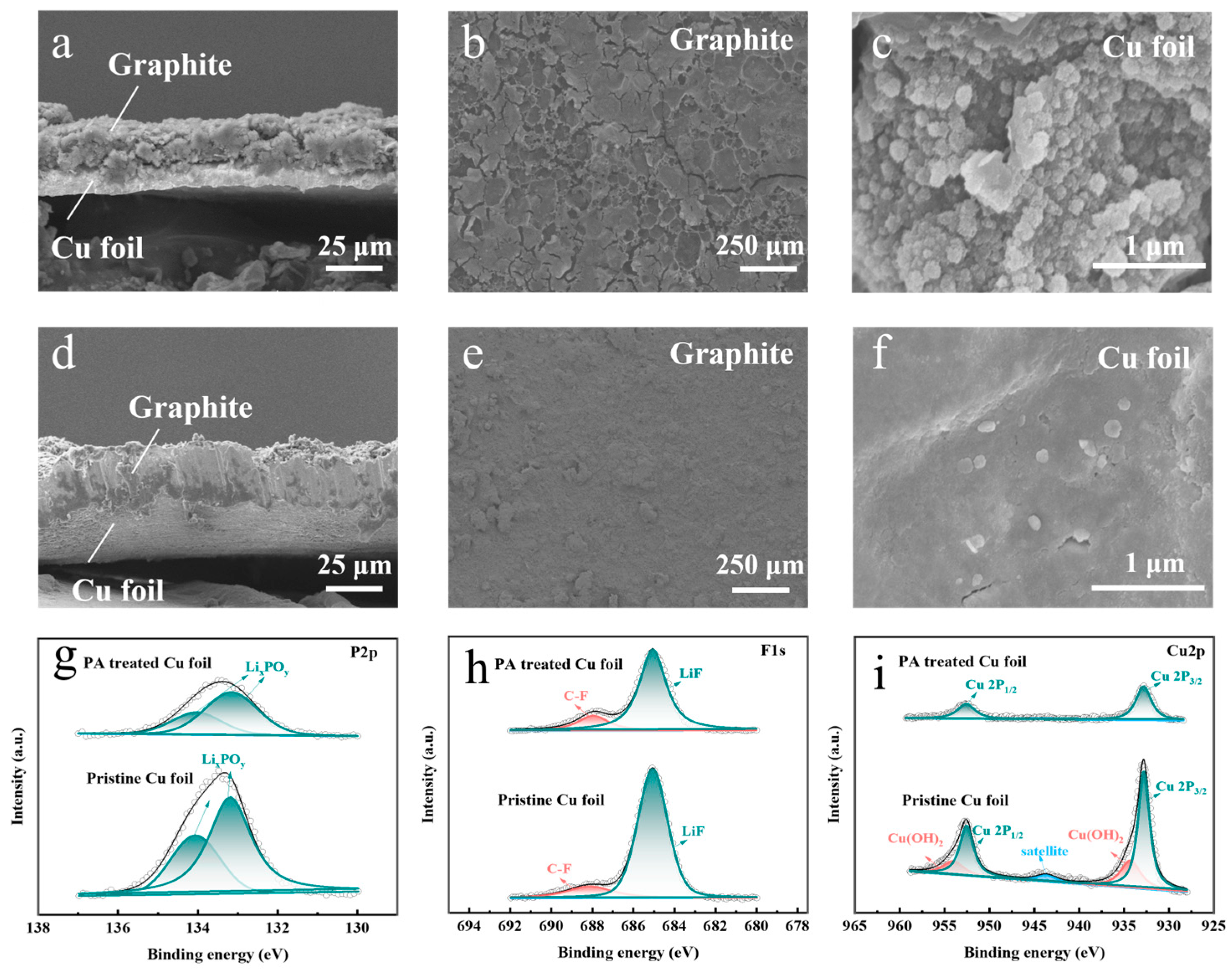
It can be observed that the performance of the graphite/Cu electrode decayed in about 200 cycles. In order to explore the reason for this cell performance decay, SEM and XPS analyses were used on the graphite/Cu and graphite/PA-Cu electrodes after 200 cycles at 0.1 A g−1 (Figure 5). Figure 5a,d show the cross-section morphology of the electrodes. Figure 5b,e show the surfaces of the electrodes, and Figure 5c,f show the copper foil surface after the ultrasonic removal of the active substance. It can be seen that the graphite and pristine Cu foil are not tightly bonded (Figure 5a) and are accompanied by cracks on the active substance (Figure 5b) and numerous spherical particles on the copper foil due to corrosion (Figure 5c). In contrast, the bonding strength of the graphite/PA-Cu electrode was still excellent after 200 cycles, with no significant cracks on the graphite and no significant spherical particles on the copper foil (Figure 5d–f).
Further XPS analysis (Figure 5g–i) was performed on the surfaces of both copper foils. LiF, C, and F corrosion products, as well as some phosphates, can be observed on the surface of the copper foils (Figure 5g,h). This indicates that there are decomposition products of the electrolyte on the surface of the copper foils, and numerous graphite particles are corroded by the electrolyte. Figure 5i reveals Cu(OH)2 (954.05 and 934.30 eV) on the surface of the pristine Cu foil, in addition to Cu 2p1/2 (952.56) and Cu 2p3/2 (932.81) [34]. However, only two peaks of Cu 2p1/2 (952.58 eV) and Cu 2p3/2 (932.83 eV) were observed on the surface of the PA-Cu foil. It is apparent that the PA film provides a protective effect to the copper foil during the low-current cycling of LIBs, resulting in reduced corrosion products and the maintenance of strong bonding between the copper foil and the active substance.
Similarly, the morphology of the graphite/Cu and graphite/PA-Cu electrodes after 200 cycles at 1 A g−1 was studied (Figure S7). Figure S7a,d show cross-sections of the electrodes, Figure S7b,e show the surfaces of the electrodes, and Figure S7c,f show the surface morphology of the copper foil after the ultrasonic removal of the active substance. It can be observed that the graphite on the pristine Cu foil extensively cracked and peeled off (Figure S7a,b). Some corrosion pits can be found on the surface of the pristine Cu foil (Figure S7c). In contrast, the PA-Cu foil was still well bonded to the graphite without visible cracks or corrosion pits on the copper foil surface (Figure S7d–f). Combined with the cycling curve at 1 A g−1, it is evident that the capacity degradation of the graphite/Cu electrode can be attributed to the active substance shedding from its surface and the severe surface corrosion of the current collector. PA film can guarantee the good bonding of the active substance to the current collector and prevent the current collector from being corroded by the electrolyte, which leads to better cell performance compared with a pristine Cu current collector.
4. Conclusions
A 5 nm thick PA film was successfully electrodeposited on the surface of electrolytic copper foil as a current collector for LIBs. The PA film rendered the electrolyte difficult to spread on the copper foil and inhibited current collector corrosion caused by the electrolyte. Moreover, the PA film could increase the bonding strength of the active substance to the copper foil, which reduces interfacial impedance during charge–discharge cycles. Cells with PA-Cu foils as current collectors exhibited enhanced cycling stability, improved capacity retention, and superior rate performance at both low and high current densities. After PA treatment, the capacity retention rate of the cell increased from 57.5% to 85.6% at the 400th cycle compared with the 2nd cycle at 0.1 A g−1. In addition, the capacity retention rate of the 500th cycle increased from 53.4% to 85.9% compared with the 100th cycle at 1 A g−1. The present study demonstrated that the surface modification of copper foil with PA films is an effective approach to enhancing the overall electrochemical performance of LIBs.
Supplementary Materials
The following supporting information can be downloaded at: https://www.mdpi.com/article/10.3390/met14020247/s1: Figure S1: (a–d) Polarization curves of copper foil with different treatment parameters and the pristine Cu foil; (e–h) EIS curves of copper foil with different treatment parameters and the pristine copper foil. Figure S2: (a) Polarization curves; (b) EIS curves of pristine Cu foil and PA-Cu foil. Figure S3: EDS energy spectra of PA-Cu. Figure S4: (a) PA-Cu foil surface and (b) pristine Cu foil surface with 1 μL electrolyte drop after 10 s. Figure S5: Peel strength of two types of copper foil. Figure S6: (a) Initial CV curves and (b) initial charge–discharge curves at 0.1A g−1 of the graphite/Cu and graphite/PA-Cu electrodes. Figure S7: SEM images of (a) the cross-section of the graphite/Cu electrode, (b) the surface of the graphite/Cu electrode, and (c) the pristine Cu foil without the active substance after 200 cycles at 1 A g−1; SEM images of (d) the cross-section of the graphite/PA-Cu electrode, (e) the surface of the graphite/PA-Cu electrode, and (f) the PA-Cu foil without the active substance after 200 cycles at 1 A g−1. Table S1: Factors and groups of PA-based passivation solutions. Table S2: Electrodepositing process parameters. Table S3: The icorr and Ecorr under different factors. Table S4: The icorr and Ecorr of the Cu foils with and without PA treatments.
Author Contributions
Conceptualization, C.G.; data curation, M.Z.; formal analysis, M.Z.; investigation, M.G. and M.Z.; methodology, M.G., J.T., X.W. and C.G.; resources, J.T., X.W. and C.G.; supervision, C.G.; writing—original draft, M.G.; writing—review and editing, M.G. and C.G. All authors have read and agreed to the published version of the manuscript.
Funding
This research was funded by the Baima Lake Laboratory Joint Funds of the Zhejiang Provincial Natural Science Foundation of China, grant number LBMHY24E030001.
Data Availability Statement
The original contributions presented in the study are included in the article/Supplementary Material, further inquiries can be directed to the corresponding author.
Conflicts of Interest
The authors declare no conflicts of interest.
References
- Armand, M.; Tarascon, J.M. Building better batteries. Nature 2008, 451, 652–657. [Google Scholar] [CrossRef]
- Dunn, B.; Kamath, H.; Tarascon, J.-M. Electrical Energy Storage for the Grid: A Battery of Choices. Science 2011, 334, 928–935. [Google Scholar] [CrossRef] [PubMed]
- Natarajan, S.; Aravindan, V. An Urgent Call to Spent LIB Recycling: Whys and Wherefores for Graphite Recovery. Adv. Energy Mater. 2020, 10, 2002238. [Google Scholar] [CrossRef]
- Zhang, Q.; Chen, H.; Luo, L.; Zhao, B.; Luo, H.; Han, X.; Wang, J.; Wang, C.; Yang, Y.; Zhu, T.; et al. Harnessing the concurrent reaction dynamics in active Si and Ge to achieve high performance lithium-ion batteries. Energy Environ. Sci. 2018, 11, 669–681. [Google Scholar] [CrossRef]
- Sandstrom, S.K.; Ji, X. Reversible halogen cathodes for high energy lithium batteries. Joule 2023, 7, 13–14. [Google Scholar] [CrossRef]
- Fan, X.; Wang, C. High-voltage liquid electrolytes for Li batteries: Progress and perspectives. Chem. Soc. Rev. 2021, 50, 10486–10566. [Google Scholar] [CrossRef]
- Ma, Q.; Zheng, Y.; Luo, D.; Or, T.; Liu, Y.; Yang, L.; Dou, H.; Liang, J.; Nie, Y.; Wang, X.; et al. 2D Materials for All-Solid-State Lithium Batteries. Adv. Mater. 2022, 34, 2108079. [Google Scholar] [CrossRef] [PubMed]
- Song, Y.-H.; Wu, K.-J.; Zhang, T.-W.; Lu, L.-L.; Guan, Y.; Zhou, F.; Wang, X.-X.; Yin, Y.-C.; Tan, Y.-H.; Li, F.; et al. A Nacre-Inspired Separator Coating for Impact-Tolerant Lithium Batteries. Adv. Mater. 2019, 31, 1905711. [Google Scholar] [CrossRef]
- Liu, C.; Wu, X.; Wang, B. Performance modulation of energy storage devices: A case of Ni-Co-S electrode materials. Chem. Eng. J. 2020, 392, 123651. [Google Scholar] [CrossRef]
- Dirican, M.; Yan, C.; Zhu, P.; Zhang, X. Composite solid electrolytes for all-solid-state lithium batteries. Mater. Sci. Eng. R Rep. 2019, 136, 27–46. [Google Scholar] [CrossRef]
- Liu, H.; Liu, X.; Li, W.; Guo, X.; Wang, Y.; Wang, G.; Zhao, D. Porous Carbon Composites for Next Generation Rechargeable Lithium Batteries. Adv. Energy Mater. 2017, 7, 1700283. [Google Scholar] [CrossRef]
- Xu, Y.; Chen, J.; Zhu, C.; Zhang, P.; Jiang, G.; Wang, C.; Zhang, Q.; Ding, N.; Huang, Y.; Zhong, S. High-performance of sodium carboxylate-derived materials for electrochemical energy storage. Sci. China Mater. 2018, 61, 707–718. [Google Scholar] [CrossRef]
- Cho, H.; Kim, Y.; Yun, Y.J.; Lee, K.S.; Shim, J.; Lee, C.-H.; Seo, J.W.; Hong, W.G.; Kim, H.J.; Kim, H.Y.; et al. Versatile 3D porous recycled carbon garments with fully-loaded active materials in the current collector for advanced lithium-ion batteries. Compos. Part B Eng. 2019, 179, 107519. [Google Scholar] [CrossRef]
- Wang, G.; Xiong, X.; Zou, P.; Fu, X.; Lin, Z.; Li, Y.; Liu, Y.; Yang, C.; Liu, M. Lithiated zinc oxide nanorod arrays on copper current collectors for robust Li metal anodes. Chem. Eng. J. 2019, 378, 122243. [Google Scholar] [CrossRef]
- Li, Y.; Guo, Q.; Wu, Y.; Ying, D.; Yu, Y.; Chi, T.; Xia, S.; Zhou, X.; Liu, Z. Artificial Graphite Paper as a Corrosion-Resistant Current Collector for Long-Life Lithium Metal Batteries. Adv. Funct. Mater. 2023, 33, 2214523. [Google Scholar] [CrossRef]
- Lee, M.-j.; Chae, M.-r.; Jeong, J.-s.; Noh, J.-p.; Ahn, H.-j.; Cho, K.-k.; Choi, H.-k.; Nam, T.-h.; Kim, K.-w.; Cho, G.-b. Si film electrodes with surface-modified Cu current collectors for micro Li batteries. Mater. Res. Bull. 2016, 82, 87–91. [Google Scholar] [CrossRef]
- Zhu, X.; Zhou, S.; Jiang, X.; Yao, X.; Xu, X.; Peng, A.; Wang, L.; Xue, Q. High-performances of Li4Ti5O12 anodes for lithium-ion batteries via modifying the Cu current collector through magnetron sputtering amorphous carbon. J. Alloys Compd. 2020, 830, 154682. [Google Scholar] [CrossRef]
- Zhang, J.; Chen, H.; Fan, B.; Shan, H.; Chen, Q.; Jiang, C.; Hou, G.; Tang, Y. Study on the relationship between crystal plane orientation and strength of electrolytic copper foil. J. Alloys Compd. 2021, 884, 161044. [Google Scholar] [CrossRef]
- He, S.-Y.; Li, C.-C. Advantages of using carbon fabric over Cu foil as conductive matrix for anodes of micro- and nano-sized Si. Mater. Res. Bull. 2022, 148, 111690. [Google Scholar] [CrossRef]
- Park, H.; Um, J.H.; Choi, H.; Yoon, W.-S.; Sung, Y.-E.; Choe, H. Hierarchical micro-lamella-structured 3D porous copper current collector coated with tin for advanced lithium-ion batteries. Appl. Surf. Sci. 2017, 399, 132–138. [Google Scholar] [CrossRef]
- An, G.-H.; Cha, S.; Ahn, H.-J. Surface functionalization of the terraced surface-based current collector for a supercapacitor with an improved energy storage performance. Appl. Surf. Sci. 2019, 478, 435–440. [Google Scholar] [CrossRef]
- Fei, X.; Dong, Z.; Gong, B.; Zhao, X. Lightweight Through-Hole Copper Foil as a Current Collector for Lithium-Ion Batteries. ACS Appl. Mater. Interfaces 2021, 13, 42266–42275. [Google Scholar] [CrossRef]
- Wojciechowski, J.; Kolanowski, Ł.; Bund, A.; Lota, G. The influence of current collector corrosion on the performance of electrochemical capacitors. J. Power Sources 2017, 368, 18–29. [Google Scholar] [CrossRef]
- Chen, J.; Zhao, Y.; Gao, H.; Chen, S.; Li, W.; Liu, X.; Hu, X.; Yan, S. Rolled electrodeposited copper foil with modified surface morphology as anode current collector for high corrosion resistance in lithium-ion battery electrolyte. Surf. Coat. Technol. 2021, 421, 127369. [Google Scholar] [CrossRef]
- Wennig, S.; Langklotz, U.; Prinz, G.M.; Schmidt, A.; Oberschachtsiek, B.; Lorke, A.; Heinzel, A. The influence of different pre-treatments of current collectors and variation of the binders on the performance of Li4Ti5O12 anodes for lithium ion batteries. J. Appl. Electrochem. 2015, 45, 1043–1055. [Google Scholar] [CrossRef]
- Nara, H.; Mukoyama, D.; Shimizu, R.; Momma, T.; Osaka, T. Systematic analysis of interfacial resistance between the cathode layer and the current collector in lithium-ion batteries by electrochemical impedance spectroscopy. J. Power Sources 2019, 409, 139–147. [Google Scholar] [CrossRef]
- Wu, J.; Zhu, Z.; Zhang, H.; Fu, H.; Li, H.; Wang, A.; Zhang, H.; Hu, Z. Improved electrochemical performance of the Silicon/Graphite-Tin composite anode material by modifying the surface morphology of the Cu current collector. Electrochim. Acta 2014, 146, 322–327. [Google Scholar] [CrossRef]
- Wotango, A.S.; Su, W.-N.; Leggesse, E.G.; Haregewoin, A.M.; Lin, M.-H.; Zegeye, T.A.; Cheng, J.-H.; Hwang, B.-J. Improved Interfacial Properties of MCMB Electrode by 1-(Trimethylsilyl)imidazole as New Electrolyte Additive to Suppress LiPF6 Decomposition. ACS Appl. Mater. Interfaces 2017, 9, 2410–2420. [Google Scholar] [CrossRef]
- Zhang, X.; Wang, A.; Lv, R.; Luo, J. A corrosion-resistant current collector for lithium metal anodes. Energy Storage Mater. 2019, 18, 199–204. [Google Scholar] [CrossRef]
- Ha, J.-K.; Haridas, A.K.; Cho, G.-B.; Ahn, H.-J.; Ahn, J.-H.; Cho, K.-K. Nano silicon encapsulated in modified copper as an anode for high performance lithium ion battery. Appl. Surf. Sci. 2019, 481, 307–312. [Google Scholar] [CrossRef]
- Zhang, C.; Liu, S.; Li, G.; Zhang, C.; Liu, X.; Luo, J. Incorporating Ionic Paths into 3D Conducting Scaffolds for High Volumetric and Areal Capacity, High Rate Lithium-Metal Anodes. Adv. Mater. 2018, 30, 1801328. [Google Scholar] [CrossRef]
- Xia, T.; Liang, T.; Xiao, Z.; Chen, J.; Liu, J.; Zhong, S. Nanograined copper foil as a high-performance collector for lithium-ion batteries. J. Alloys Compd. 2020, 831, 154801. [Google Scholar] [CrossRef]
- Nourmohammadi Miankushki, H.; Sedghi, A.; Saeid, B. Comparison of copper compounds on copper foil as current collector for fabrication of graphene/polypyrrole electrode. J. Energy Storage 2018, 19, 201–212. [Google Scholar] [CrossRef]
- Xiao, Z.; Rao, X.; Chen, J.; Potapenko, H.; Zhang, Q.; Zhong, S. Organic carbonized copper foil facilitates the performance of the current collector for lithium-ion batteries. Mater. Chem. Front. 2022, 6, 2478–2490. [Google Scholar] [CrossRef]
- Zhao, Y.; Chen, X.-H.; Hu, J.-M. A novel and facile method for constructing micro-nano porous phytic acid pretreatment layer on metal surface. Corros. Sci. 2021, 186, 109464. [Google Scholar] [CrossRef]
- Zhang, Y.; Peng, C.; Zeng, Z.; Zhang, X.; Zhang, L.; Ma, Y.; Wang, Z. Sustainable Phytic Acid–Zinc Anticorrosion Interface for Highly Reversible Zinc Metal Anodes. ACS Appl. Mater. Interfaces 2022, 14, 10419–10427. [Google Scholar] [CrossRef] [PubMed]
- Gao, X.; Zhao, C.; Lu, H.; Gao, F.; Ma, H. Influence of phytic acid on the corrosion behavior of iron under acidic and neutral conditions. Electrochim. Acta 2014, 150, 188–196. [Google Scholar] [CrossRef]
- Yan, R.; Gao, X.; He, W.; Guo, R.; Wu, R.; Zhao, Z.; Ma, H. A simple and convenient method to fabricate new types of phytic acid–metal conversion coatings with excellent anti-corrosion performance on the iron substrate. RSC Adv. 2017, 7, 41152–41162. [Google Scholar] [CrossRef]
- Shen, S.; Guo, X.-y.; Song, P.; Pan, Y.-C.; Wang, H.-q.; Wen, Y.; Yang, H.-F. Phytic acid adsorption on the copper surface: Observation of electrochemistry and Raman spectroscopy. Appl. Surf. Sci. 2013, 276, 167–173. [Google Scholar] [CrossRef]
- Wang, W.-j.; Liu, J.; Liu, X.-f.; Li, Q.-w. Electrodeposited chromate-free organic passive film on the rolled copper foil. Prog. Org. Coat. 2022, 163, 106663. [Google Scholar] [CrossRef]
- Xu, X.; Su, H.; Zhang, J.; Zhong, Y.; Xu, Y.; Qiu, Z.; Wu, H.B.; Wang, X.; Gu, C.; Tu, J. Sulfamate-Derived Solid Electrolyte Interphase for Reversible Aqueous Zinc Battery. ACS Energy Lett. 2022, 7, 4459–4468. [Google Scholar] [CrossRef]
- Xu, X.; Xu, Y.; Zhang, J.; Zhong, Y.; Li, Z.; Qiu, H.; Wu, H.B.; Wang, J.; Wang, X.; Gu, C.; et al. Quasi-Solid Electrolyte Interphase Boosting Charge and Mass Transfer for Dendrite-Free Zinc Battery. Nano-Micro Lett. 2023, 15, 56. [Google Scholar] [CrossRef] [PubMed]
- Xu, Y.; Wu, H.; Jia, H.; Engelhard, M.H.; Zhang, J.-G.; Xu, W.; Wang, C. Sweeping potential regulated structural and chemical evolution of solid-electrolyte interphase on Cu and Li as revealed by cryo-TEM. Nano Energy 2020, 76, 105040. [Google Scholar] [CrossRef]
Figure 1.
Flow chart of the PA treatment of Cu foil and the preparation of the anode for assembling LIBs.
Figure 1.
Flow chart of the PA treatment of Cu foil and the preparation of the anode for assembling LIBs.
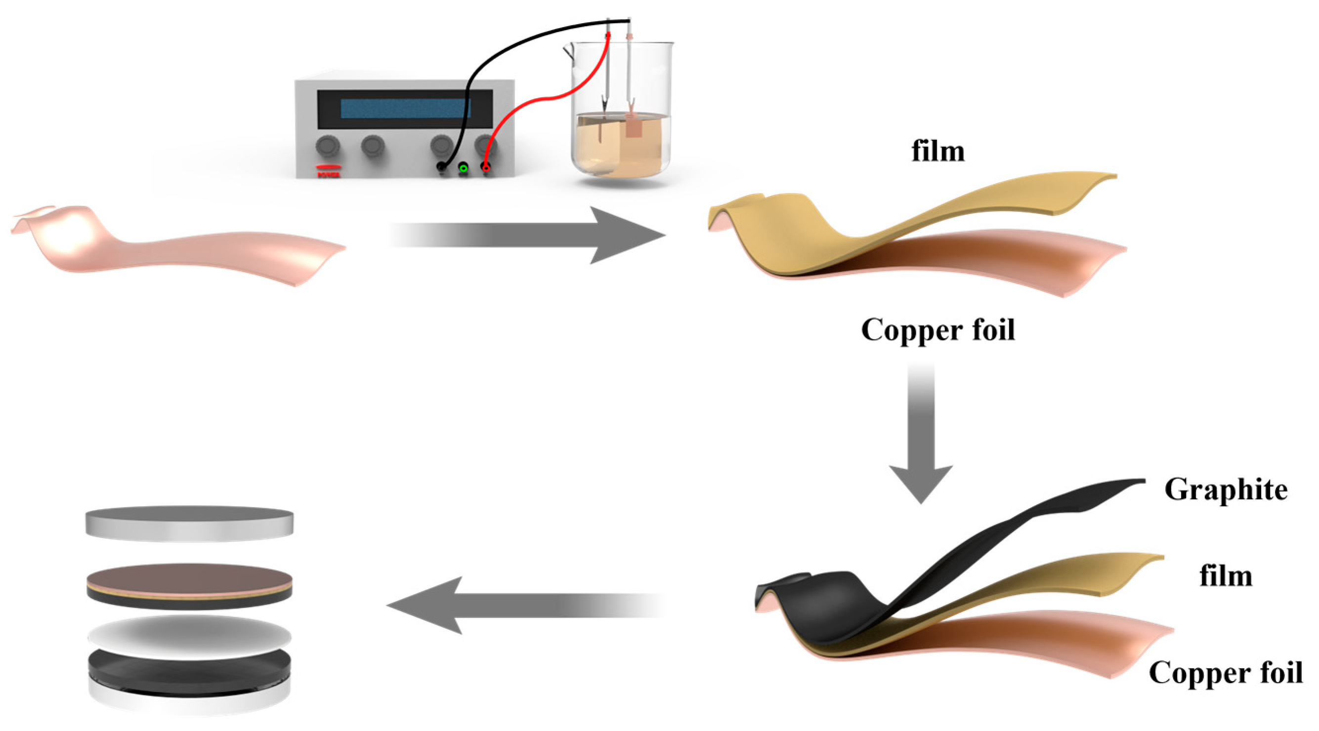
Figure 2.
Surface morphology of the (a) pristine Cu foil and the (b) PA-Cu foil. (c) FTIR spectra of the PA solution, PA-Cu foil, and pristine Cu foil; (d) TEM image of PA-Cu. Surface morphology of the (e) pristine Cu foil and (f) PA-Cu foil after immersion in the electrolyte for 15 days.
Figure 2.
Surface morphology of the (a) pristine Cu foil and the (b) PA-Cu foil. (c) FTIR spectra of the PA solution, PA-Cu foil, and pristine Cu foil; (d) TEM image of PA-Cu. Surface morphology of the (e) pristine Cu foil and (f) PA-Cu foil after immersion in the electrolyte for 15 days.
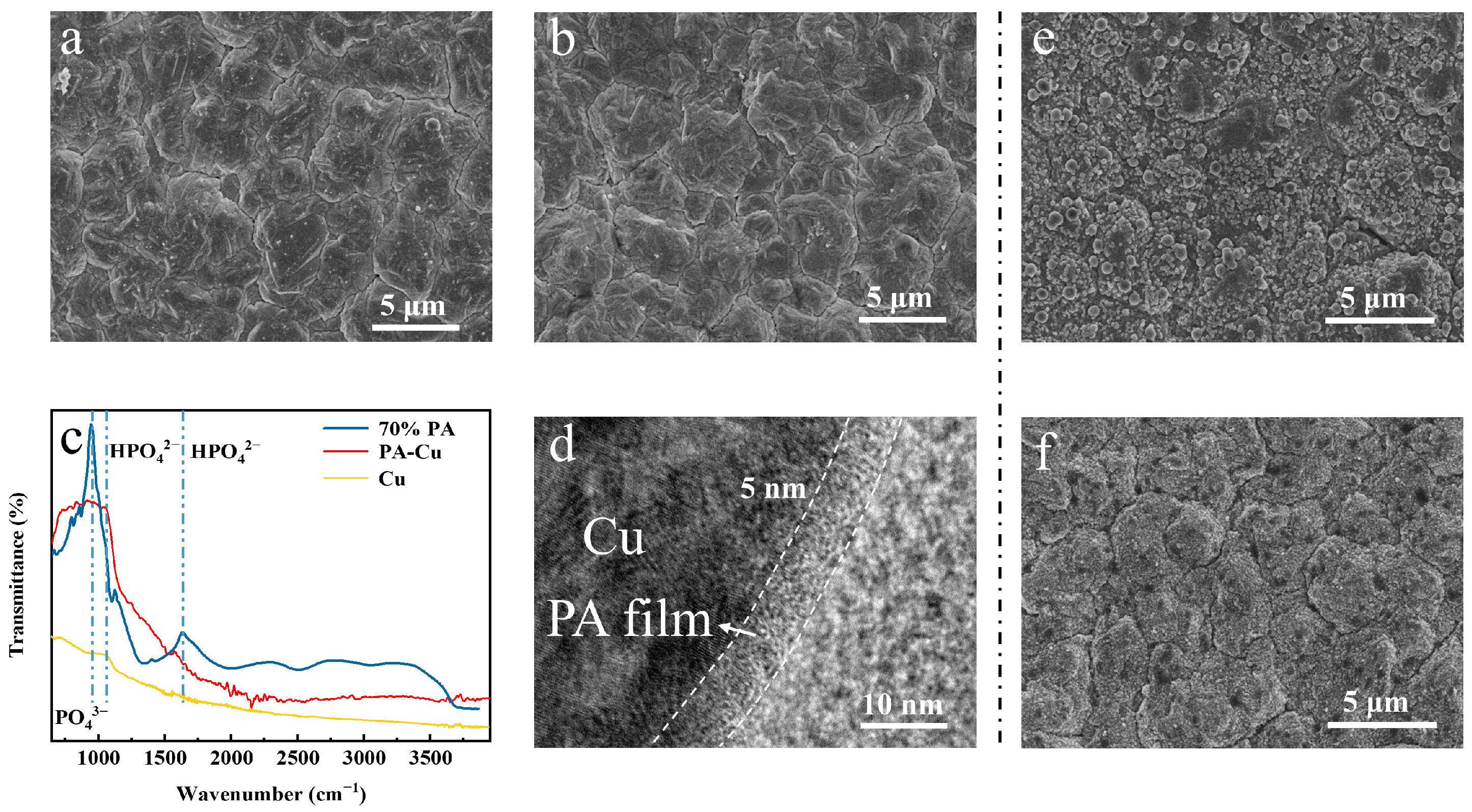
Figure 3.
XPS spectra of pristine Cu foil and PA-Cu foil, (a) P 2p; (b) F 1s; (c) Cu 2p, immersed in electrolyte for 15 days. XPS spectra of pristine Cu foil: (d) P 2p; (e) F 1s; (f) Cu 2p.
Figure 3.
XPS spectra of pristine Cu foil and PA-Cu foil, (a) P 2p; (b) F 1s; (c) Cu 2p, immersed in electrolyte for 15 days. XPS spectra of pristine Cu foil: (d) P 2p; (e) F 1s; (f) Cu 2p.
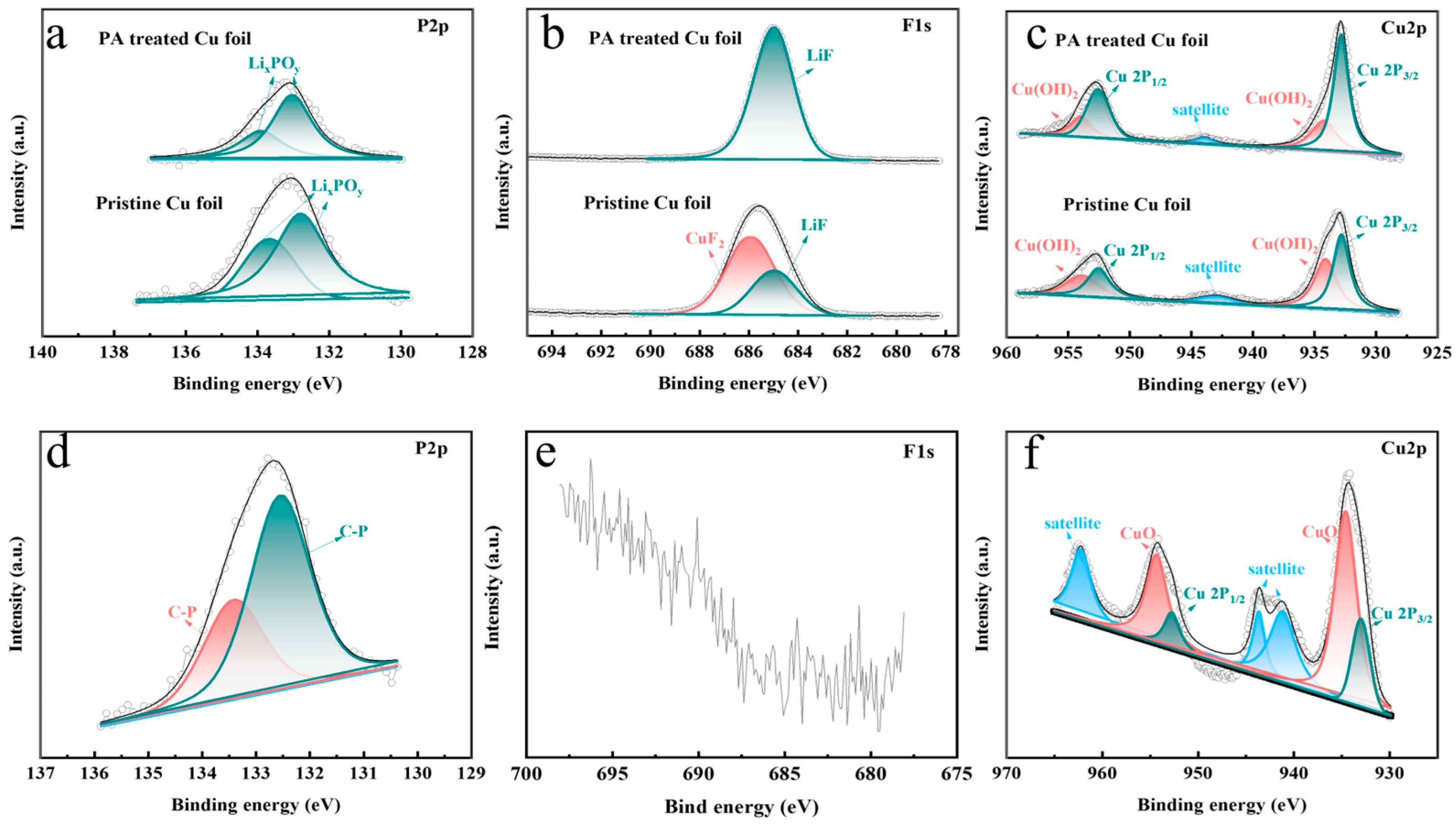
Figure 4.
(a) Cycling properties of the graphite/Cu and graphite/PA-Cu electrodes at 0.1 A g−1 between 0.01 and 3 V; (b) EIS curves of the two cells after 200 cycles at 0.1 A g−1 between 0.01 and 3 V; (c) rate performance of the two cells at 0.1 A g−1, 0.2 A g−1, 0.5 A g−1, 1.0 A g−1, 2.0 A g−1; (d) cycling properties of the two cells at 1 A g−1 after 20 cycles at 0.1 A g−1 between 0.01 and 3 V.
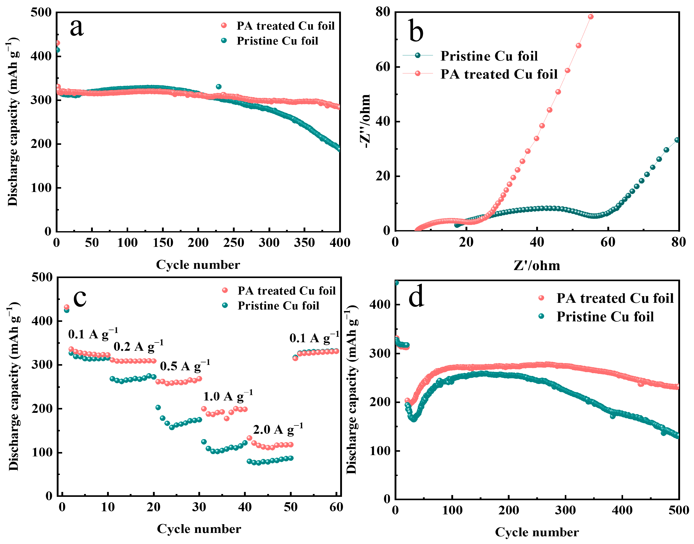
Figure 5.
SEM image of (a) the cross-section of the graphite/Cu electrode, (b) the surface of the graphite/Cu electrode, and (c) the pristine Cu foil without the active substance after 200 cycles at 0.1 A g−1; SEM image of (d) the cross-section of the graphite/PA-Cu electrode, (e) the surface of the graphite/PA-Cu electrode, and (f) the PA-Cu foil without the active substance after 200 cycles at 0.1 A g−1; (g–i) XPS spectra of pristine copper foil and PA-Cu foil after 200 cycles at 0.1 A g−1.
Disclaimer/Publisher’s Note: The statements, opinions and data contained in all publications are solely those of the individual author(s) and contributor(s) and not of MDPI and/or the editor(s). MDPI and/or the editor(s) disclaim responsibility for any injury to people or property resulting from any ideas, methods, instructions or products referred to in the content. |
© 2024 by the authors. Licensee MDPI, Basel, Switzerland. This article is an open access article distributed under the terms and conditions of the Creative Commons Attribution (CC BY) license (https://creativecommons.org/licenses/by/4.0/).
Share and Cite
MDPI and ACS Style
Gan, M.; Zhu, M.; Tu, J.; Wang, X.; Gu, C. Phytic-Acid-Modified Copper Foil as a Current Collector for Lithium-Ion Batteries. Metals 2024, 14, 247. https://doi.org/10.3390/met14020247
AMA Style
Gan M, Zhu M, Tu J, Wang X, Gu C. Phytic-Acid-Modified Copper Foil as a Current Collector for Lithium-Ion Batteries. Metals. 2024; 14(2):247. https://doi.org/10.3390/met14020247
Chicago/Turabian StyleGan, Mingtao, Mengjun Zhu, Jiangping Tu, Xiuli Wang, and Changdong Gu. 2024. "Phytic-Acid-Modified Copper Foil as a Current Collector for Lithium-Ion Batteries" Metals 14, no. 2: 247. https://doi.org/10.3390/met14020247
Note that from the first issue of 2016, this journal uses article numbers instead of page numbers. See further details here.