
First-Principles Study of Cu Addition on Mechanical Properties of Ni3Sn4-Based Intermetallic Compounds
by
 and
and
Jinye Yao
1,
Li Wang
1,
Shihao Guo
1,
Xiaofu Li
1,
Xiangxu Chen
1,
Min Shang
1,
Haoran Ma
2 and
Haitao Ma
1,* 1
School of Materials Science and Engineering, Dalian University of Technology, Dalian 116000, China
2
School of Microelectronics, Dalian University of Technology, Dalian 116024, China
*
Author to whom correspondence should be addressed.
Metals 2024, 14(1), 64; https://doi.org/10.3390/met14010064
Submission received: 1 December 2023
/
Revised: 31 December 2023
/
Accepted: 3 January 2024
/
Published: 5 January 2024
(This article belongs to the Special Issue Advanced Studies in Solder Joints)
Abstract
:Ni–Cu under-bump metallisation (UBM) can reduce stress and improve wetting ability in technology for electronic packaging technology advances with three-dimensional integrated circuit (3D IC) devices. The bond between the Sn-based solder and Ni–Cu UBM is affected by the formation of intermetallic compounds (IMCs), specifically Ni3Sn4 and (Ni,Cu)3Sn4. This paper investigates the mechanical properties of IMCs, which are critical in assessing the longevity of solder joints. First-principles calculations were carried out to investigate the phase stability, mechanical properties and electronic structures of Ni3Sn4, Ni2.5Cu0.5Sn4, Ni2.0Cu1.0Sn4, and Ni1.5Cu1.5Sn4 IMCs. The calculated formation enthalpies show that the doping of Cu atoms leads to a decrease in the stability of the phases and a reduction in the mechanical properties of the Ni3Sn4 crystal structure. As the concentration of Cu atoms in the Ni3Sn4 cells increases, the bulk modulus values of (Ni,Cu)3Sn4 formed with different compositions decrease from 107.78 GPa to 87.84 GPa, the shear modulus decreases from 56.64 GPa to 45.08 GPa, and the elastic modulus decreases from 144.59 GPa to 115.48 GPa, indicating that the doping of Cu atoms into the Ni3Sn4 cells may adversely affect their mechanical properties and increase the possibility of microcracking at the interface during actual service. The anisotropy of (Ni,Cu)3Sn4 is more significant than that of Ni3Sn4, with Ni2.0Cu1.0Sn4 showing the highest anisotropy. After evaluating the electronic structures, the metallic properties of Ni3Sn4 and the Ni2.5Cu0.5Sn4, Ni2.0Cu1.0Sn4, and Ni1.5Cu1.5Sn4 phases are revealed by electronic structure analysis. The total density of states (TDOS) for (Ni,Cu)3Sn4 structures is mainly influenced by Ni-d and Cu-d states. The addition of Cu atoms can increase the brittleness of Ni3Sn4. In addition, the region where d and p hybridisation occurs gradually increases with increasing Cu content. The electronic properties suggest that the binding energy between Ni and Sn atoms weakens with the addition of Cu atoms, resulting in a decrease in the elastic modulus. This research can serve as a valuable reference and theoretical guide for future applications of these materials.
1. Introduction
Three-dimensional electronic packaging technology can meet the high-density assembly performance requirements of today’s electronic products while also providing high reliability, fast transmission speeds, low power consumption, low cost, and light weight [1,2,3]. At the same time, there can be concerns about the reliability of solder joints as they become smaller and smaller [4]. The reliability of microelectronic brazed interconnects is primarily influenced by the wetting behaviour of the solder bump, as well as the interfacial reactions between the solder and the metal layer beneath the bump during production and service, and electron migration. The bonding of the Sn-based solder/UBM interface during the soldering process is influenced by the physicochemical properties of the interacting materials, in particular the diffusion process and the resulting formation of various intermetallic compounds (IMCs) [5,6]. Meanwhile, the changes in the interfacial microstructure and mechanical properties of solder joints are usually the cause of serious reliability problems. Thick IMC layers have been found to weaken the mechanical properties and cause reliability problems, while thin IMC layers can increase the strength of the joint [7]. As the demand for smaller electronic devices increases, solder joints are shrinking in size. This decrease in solder volume increases the volume fraction of IMCs in the total solder joint volume, making the interface behaviour more important. In fact, the mechanical properties of IMCs largely determine the failure mechanisms of solder joints, which have emerged as a critical issue in solder reliability [8,9,10]. Therefore, it is crucial to understand the mechanical properties of IMCs in order to assess the reliability of solder joints in electronic packaging.
For example, due to the difference in ductility between the IMC layer and substrate, the stress distribution within solder joints is altered during reflow and ageing. To achieve slower reaction rates or more stable IMCs, the composition of UBM films can be adjusted. Compared to copper (Cu) UBM, nickel (Ni) UBM exhibits a reduced interfacial reaction with solders, as shown in previous research [11,12,13,14]. Ni and Ni-based alloys are known to have favourable magnetic properties, excellent mechanical properties and excellent corrosion and abrasion resistance. A variety of Ni-based UBMs have been used in industry to improve reliability [15]. These include widely used UBMs such as electroplated Ni, sputtered Ni(V) and electroless Ni(P)/Au. However, Ni UBM has a notable disadvantage in the form of inherent stress generation during the plating process [16,17]. After investigating the detrimental effects of Ni film and considering the potential of Ni–Cu to reduce stress and improve wetting, the use of Ni–Cu UBM as a replacement for Ni UBM is a viable option.
For this reason, interfacial reactions and IMC growth between Sn-based and Ni–Cu substrates have been the subject of much interest. Sn-based solders react with Ni coatings, primarily forming the intermetallic compound Ni3Sn4 [18,19,20]. In addition, Sn–Ag–Cu ternary lead-free solders are considered to be some of the best candidates for replacing conventional Sn–Pb solders in electronic packaging due to their desirable properties. It has also been observed by other researchers that Cu atoms can also replace Ni atoms in sublattice positions of Ni3Sn4 to form a ternary intermetal, (Ni,Cu)3Sn4. It is possible that the mechanical properties of Ni3Sn4 can be altered by doping with Cu atoms. However, most research on (Ni,Cu)3Sn4 has been experimental. Few studies have focused on the mechanical properties of (Ni,Cu)3Sn4 [21,22]. Further studies are needed to investigate the stability of (Ni,Cu)3Sn4 in more detail. The initial stage of first-principles calculations involves identifying the most stable geometric structure corresponding to the lowest energy, as well as determining the electronic, thermodynamic, and optical properties of a material through self-consistent calculations based on the laws of quantum mechanics and its constituent atoms [23,24]. In this paper, first-principles calculations are used as a convenient scheme to derive the essential properties of materials. The effect of Cu additions on the mechanical properties of Ni3Sn4 IMCs is investigated in this work. We will perform first-principles calculations on Ni3Sn4, Ni2.5Cu0.5Sn4, Ni2.0Cu1.0Sn4, and Ni1.5Cu1.5Sn4 to derive their structural, elastic, thermodynamic and electronic properties. The results of our systematic research will complement the physical property data and facilitate the discovery of intermetallic structural stability and mechanical properties.
2. First-Principles Calculation Details
The initial model for this study was taken from the experimental crystal structure of Ni3Sn4 [25]. Figure 1a shows the primitive structure of the Ni3Sn4 phase, which was a monoclinic structure in the C2/m space group and contained six Ni and eight Sn atoms per cell. It can be seen that the Ni atoms occupy two different positions, 2a (Ni1) and 4i (Ni2). Ni1 is located at the eight top angles of the hexahedron and the face centre position of the xy plane, while Ni2 is located in the interior of the hexahedron and the xz plane [26]. The formation enthalpy calculations show that Ni2.5Cu0.5Sn4(2a) has a value of −219.65 meV/atom and Ni2.5Cu0.5Sn4 (4i) has a value of −226.19 meV/atom. This suggests that Cu has a greater tendency to occupy the 4i site [27]. In this paper, only the substitution of the Ni 4i position is discussed. It was found that during reflow and ageing, the diffusion of Cu atoms to the interface gradually decreases with the increasing addition of Ni. When using SAC-1Ni as the soldering material, the resulting IMC (Ni,Cu)3Sn4 contains 10.17–27.2% Cu [28,29]. According to the formulas of Ni2.5Cu0.5Sn4, Ni2.0Cu1.0Sn4 and Ni1.5Cu1.5Sn4, different amounts of Cu (7.14 at.%, 14.3 at.% and 21.4 at.%, respectively) were added to the Ni3Sn4 phase, which are shown in Figure 1b–d.
In this study, first-principles calculations using density functional theory (DFT) were performed using the Cambridge Sequential Total Energy Package (CASTEP, 2017, Dassault Systèmes is located in Paris, France) [30]. To ensure the accuracy of subsequent calculations and to obtain the most stable crystal structure, strict total energy convergence tests were implemented. An energy threshold of 400 eV and 3 × 9 × 7 Monkhorst-Pack k-points were used to calculate the lattice parameters and elastic constants (Cij) for the Ni3Sn4, Ni2.5Cu0.5Sn4, Ni2.0Cu1.0Sn4, and Ni1.5Cu1.5Sn4 phases.
The Generalised Gradient Approximation (GGA) was used to treat the exchange and correlation function in terms of the Perdew–Burke–Ernzerhof (PBE) exchange–correlation energy [31]. The stability of intermetallic compounds can be determined by comparing their formation energies. In general, a compound will only form if its energy is less than the sum of the energies of the individual crystals. Therefore, the more negative the formation energy, the more stable the resulting compound will be. In order to study the thermodynamic stability, the heats of formation for Ni3Sn4, Ni2.5Cu0.5Sn4, Ni2.0Cu1.0Sn4, and Ni1.5Cu1.5Sn4 were calculated using the following formula:
in which Etotal(NixCuySnz) is the calculated total energy of NixCuySnz at equilibrium lattice constants. The energies of the isolated Ni, Cu and Sn atoms are given as Etotal(Ni), Etotal(Cu)and Etotal(Sn), respectively. In NixCuySnz, x, y and z denote the number of Ni, Cu and Sn atoms, respectively.
3. Results and Discussion
3.1. Structure Optimisation
For Ni3Sn4, Ni2.5Cu0.5Sn4, Ni2.0Cu1.0Sn4, and Ni1.5Cu1.5Sn4, the optimised structural parameters calculated are shown in Table 1. These results are discussed in this paper along with other literature [26,32,33]. Our analysis showed that the structural parameters calculated in this work have minimal deviations from the existing literature, and the deviations are less than 1.0%. This demonstrates the validity of the theoretical approaches used. It was observed that the lattice constants remained largely unaffected by the addition of Cu to all phases. This indicates that there were no changes in the crystal structures following the introduction of Cu atoms into the Ni3Sn4 phase. To determine the effect of Cu additions on the phase stability of Ni3Sn4, the heat of formation (ΔH, meV/atom) for Ni3Sn4, Ni2.5Cu0.5Sn4, Ni2.0Cu1.0Sn4, and Ni1.5Cu1.5Sn4 at zero temperature, we calculated the heat of formation using Equation (1). The results are given in Table 1. A negative ΔH indicates the stability of the studied phase and a larger negative energy implies a more stable structure. The heat of formation of Ni3Sn4 in this work was −284 meV/atom, close to the previously calculated results of −260, −267, and −269 meV/atom. As shown in Figure 2, when Cu atoms were added to the Ni3Sn4 structure, the heat of formation increased slightly, with ΔH = −248 meV/atom for Ni2.5Cu0.5Sn4, ΔH = −205 meV/atom for Ni2.0Cu1.0Sn4, and ΔH = −165 meV/atom for Ni1.5Cu1.5Sn4. The structure of Ni3Sn4 was found to be more stable than that of (Ni,Cu)3Sn4 IMCs. In simple terms, the introduction of Cu atoms reduced the structural integrity of the Ni3Sn4 IMC. Increasing the number of Cu atoms leads to a decrease in the stability of the structure.
3.2. Mechanical Properties
This study investigates the effect of Cu addition on the mechanical properties of Ni3Sn4. The elastic constant (Cij) of Ni3Sn4-based structures was calculated. The elastic constant (Cij) characterises the elasticity of a material and is represented by the quadratic coefficient in the case of small strains [34]. The matrix of elastic constants can be summarised in 13 variables, based on the symmetry of monoclinic structures [35].
The Cij results obtained are listed in Table 2. The mechanical stability of the crystal structure could be determined by using independent elastic constants, while for a monoclinic structure composed of Ni3Sn4-based IMCs, the conditions required for mechanical stability can be defined as follows:
Table 2 shows the calculated elastic constants (Cij) for all Ni3Sn4-based structures. The elastic constants (Cij) of Ni3Sn4 are close to the other calculations [26,32,33]. C11 represents the elastic deformation resistance of the crystal structures in the [100] direction [36]. It can be observed that the value of C11 for Ni3Sn4 is 165.96 GPa, which is higher than that of (Ni,Cu)3Sn4. This suggests that Ni3Sn4 exhibits the highest resistance to elastic deformation. From Table 2, the elastic constants (Cij) were calculated for all the Ni3Sn4-based structures; (Ni,Cu)3Sn4 structures typically have lower elastic constants (Cij) than Ni3Sn4. And the corresponding criteria listed in Equations (2)–(4) were easily satisfied, indicating that the Ni3Sn4-based structures studied are mechanically stable at 0 K.
In order to further approximate the Young modulus of Ni3Sn4-based ternary structures in the polycrystalline state [37], Voight–Reuss–Hill (VRH) [38] can be applied. The Voigt (V) and Reuss (R) for bulk and shear modulus can be calculated as follows:
The following equations were used to calculate the bulk modulus (B), shear modulus (G), Young modulus (E) and Poisson ratio (ν). where BV, BR, GV and GR are the bulk and shear modulus in VRH.
The values for B, G, E, ν and B/G of Ni3Sn4-based IMCS can be obtained using Equations (16)–(19). The results are shown in Figure 3 and Table 3. The B, G, E, ν and B/G of Ni3Sn4 are 107.78 GPa, 56.64 GPa, 144.59 GPa, 0.276 and 1.90, respectively, which are close to the results of other references.
Bulk modulus values for different compositions are documented as 107.78 GPa (Ni3Sn4), 98.79 GPa (Ni2.5Cu0.5Sn4), 91.93 GPa (Ni2.0Cu1.0Sn4), and 87.84 GPa (Ni1.5Cu1.5Sn4). In addition, the shear modulus and Young modulus of Ni3Sn4 were 56.64 GPa and 144.59 GPa, respectively. After the addition of Cu to the Ni3Sn4 structure, the shear modulus and Young’s modulus were significantly reduced. It can be observed that Cu addition had a significant effect on the mechanical properties of the studied Ni3Sn4-based alloys. For Ni2.5Cu0.5Sn4, the values were G = 52.23 GPa and E = 133.21 GPa; for Ni2.0Cu1.0Sn4, the values were G = 46.24 GPa and E = 118.80 GPa; and for Ni1.5Cu1.5Sn4, the values were G = 45.08 GPa and E = 115.48 GPa. The incorporation of Cu atoms into Ni3Sn4 crystals is predicted to reduce the binding energy in structures containing Ni3Sn4. This could lead to a lower shear modulus and Young modulus.
According to Pugh’s criterion [39], the B/G ratio is proposed as a condition to distinguish between brittle and ductile materials. If the value exceeds 1.75, the material has ductile properties, otherwise it is brittle. The B/G ratios for Ni3Sn4, Ni2.5Cu0.5Sn4, Ni2.0Cu1.0Sn4, and Ni1.5Cu1.5Sn4 are 1.90, 1.89, 1.99 and 1.95, respectively. Therefore, all phases based on Ni3Sn4 can be classified as ductile, with the Ni3Sn4 IMC exhibiting the highest ductility of all the structures investigated. In addition, the Poisson ratio (ν) can be considered as a parameter to represent the ductile or brittle behaviour of materials when ν is above or below 0.25 [40].
From the Poisson ratio shown in Table 3, it was expected that all phases based on Ni3Sn4 would exhibit ductility. It is possible to predict the Young modulus of IMCs using first-principles calculations. Nevertheless, the plastic properties of materials are influenced by various factors such as crystal structure, microstructure and experimental conditions. It is widely accepted that material mechanics are strongly influenced by the growth and progression of microcracks. During the manufacture and use of solder joints, the anisotropic plastic deformation of intermetallic compounds leads to the formation of microcracks, which affect the reliability of electronic products [41]. To investigate the effect of the introduction of Cu on the elastic anisotropy of a Ni3Sn4 IMC, the universal anisotropy index (AU) was used. A higher value of AU indicates a greater structural anisotropy of the materials.
AU could be expressed as the following:
If AU has a value of zero, a crystal structure should be isotropic. A higher value of AU indicates greater anisotropy for a material. The values of AU for Ni3Sn4-based IMCs can be obtained using Equation (20). The results are given in Figure 4 and Table 4. The atomic unit (AU) of Ni3Sn4 is 0.271, which is close to other references. Obviously, both Ni3Sn4 and (Ni,Cu)3Sn4 must be considered anisotropic materials. The addition of copper would increase the mechanical anisotropy of the Ni3Sn4 intermetallic compound. The increase in elastic anisotropy resulted in a greater propensity for microcracking in Ni3Sn4, which reduced the shear strength of brazed joints. In order to gain further insight into the elastic anisotropy of Ni3Sn4-based phases, 3D surface plots of the bulk modulus and Young modulus were made in the present study.
As shown in Figure 5, the ability of a material to resist deformation is expressed by its bulk modulus, B, which is determined by the strength and compressibility of the chemical bonds. The higher the bulk modulus of a material, the higher the corresponding strength of the material. Where the greater deviation from the spherical shape indicates greater anisotropy, it can be seen that the bulk modulus anisotropy of (Ni,Cu)3Sn4 is overall greater than that of undoped Ni3Sn4 as the copper atom content increases. As indicated in Figure 6, it was observed that for all structures based on Ni3Sn4, 3D surface plots displayed some deviations from a spherical shape. This is indicative of the elastic anisotropies of Ni3Sn4 and (Ni,Cu)3Sn4. Moreover, after the Cu doping, the shape of the directional modulus was further away from the sphere, indicating the stronger elastic anisotropy of (Ni,Cu)3Sn4. And the Ni2.0Cu1.0Sn4 had the strongest anisotropy.
3.3. Electronic Structures
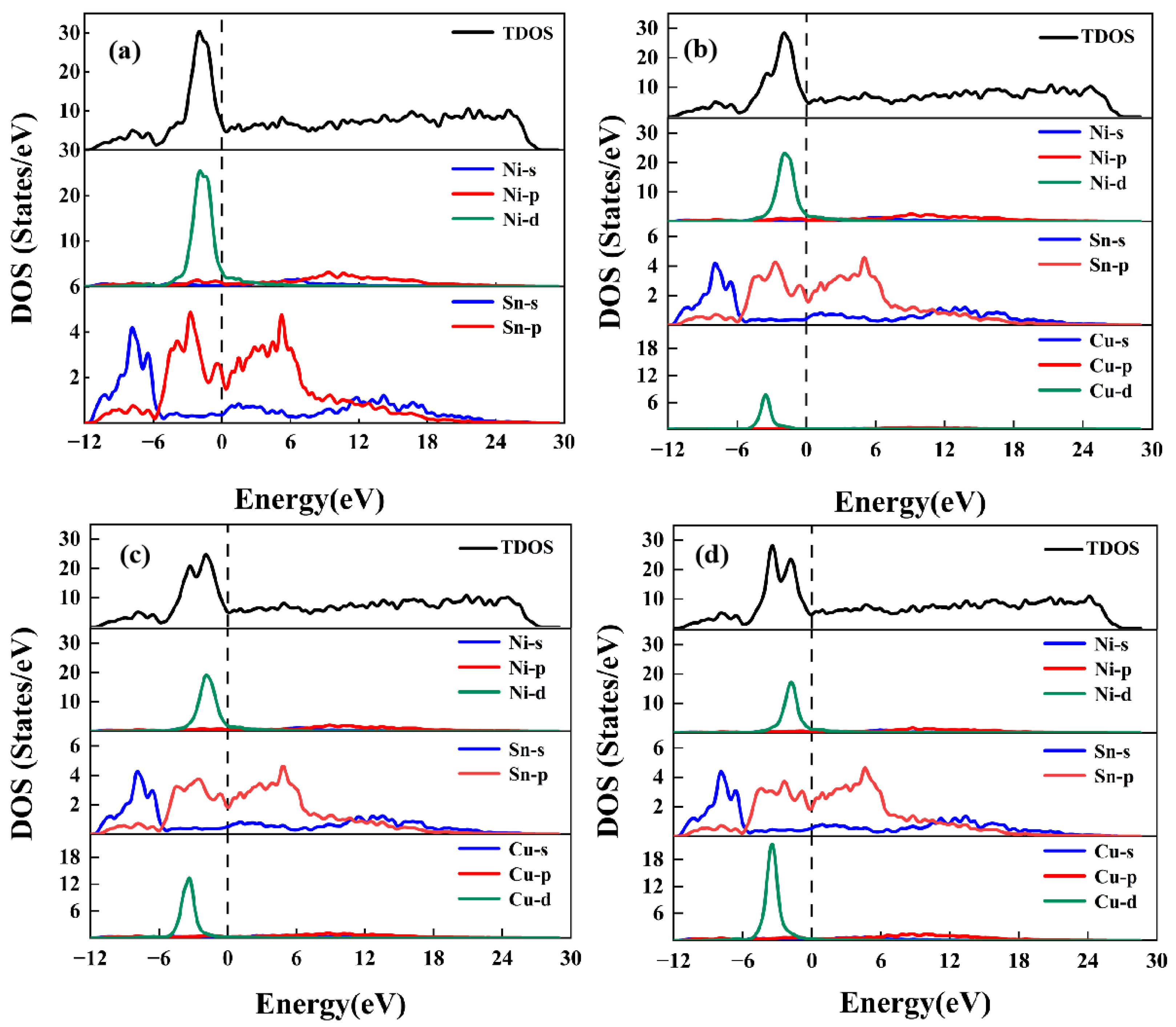
The stability and bonding characteristics of a material are closely related to its electronic structure. In order to reveal the fundamental chemical bonding of the Ni3Sn4-based IMCs, the total density of states (TDOS) and partial density of states (PDOS) were performed and are shown in Figure 7. The Fermi levels are shown at zero energy in both TDOS and PDOS. Any non-zero states observed in the Fermi levels indicate the metallic nature of these IMCs. The electronic property indicates that the Ni3Sn4, Ni2.5Cu0.5Sn4, Ni2.0Cu1.0Sn4, and Ni1.5Cu1.5Sn4 phases exhibit metallic properties.
As shown in Figure 7a, the TDOS in the energy range of about −12 to −6 eV is predominantly contributed by the Sn-s state. In the region from about −6 eV to the Fermi level, the dominant parts of the TDOS are the Ni-d state and the Sn-p state. It is evident that the Ni-d states, which have undergone a slight hybridisation with the Sn-p states, form the primary component close to the Fermi level in Ni3Sn4. Compared to the Ni3Sn4 phase, the peak of the TDOS from −6 eV to the Fermi level has a reduced height as shown in Figure 7b–d. The Fermi level reflects the stability of the material. Material stability decreases as the TDOS value increases [42]. The TDOS for (Ni,Cu)3Sn4 structures is primarily influenced by Ni-d and Cu-d states. The relationship between the electronic structure and the ductility and brittleness of crystal structures is well established [43]. The strength of atomic interactions can be inferred from the overlap region of d- and p-hybridised orbitals. The addition of Cu atoms can increase the brittleness of Ni3Sn4. Furthermore, the d- and p-hybridised area gradually increases with the increase in Cu content.
This suggests that the hybridisation between the Ni-d and Sn-p electrons was weakened after Cu replaced Ni in Ni3Sn4. In addition, a new peak appears from −6 eV to 0 eV, which is mainly dominated by Cu-d electrons. The peak position of the Cu-d state corresponded to the position of the Sn-p saddle point at an energy level of about −4 eV. Therefore, the doped Cu atoms could not adapt to the loss of bonding between Sn and Ni. In short, the binding energy of Ni3Sn4 exceeded that of Ni3Sn4-based IMCs. It is well known that a higher binding energy corresponds to a stronger charge interaction [44], which leads to an increase in structural stability. The results may explain the difference in elastic properties observed between Ni3Sn4 and Ni2.5Cu0.5Sn4, Ni2.0Cu1.0Sn4, and Ni1.5Cu1.5Sn4.
4. Conclusions
In this study, Ni3Sn4-based IMCs are modelled by first-principles calculations to investigate the crystal structures and mechanical properties, as well as the electronic properties of the substitution of Cu for Ni in Ni3Sn4. We use the predictions of the systematic work calculated from first principles. As the concentration of Cu atoms in the Ni3Sn4 cells increases, the bulk modulus values of (Ni,Cu)3Sn4 formed with different compositions decrease from 107.78 GPa to 87.84 GPa, the shear modulus decreases from 56.64 GPa to 45.08 GPa, and the elastic modulus decreases from 144.59 GPa to 115.48 GPa, indicating that the doping of Cu atoms into the Ni3Sn4 cells may adversely affect their mechanical properties and increase the possibility of microcracking at the interface during actual service. It is also found that the anisotropy of (Ni,Cu)3Sn4 is more pronounced than that of Ni3Sn4, with the highest anisotropy observed in Ni2.0Cu1.0Sn4. The metallic properties of Ni3Sn4 and the Ni2.5Cu0.5Sn4, Ni2.0Cu1.0Sn4, and Ni1.5Cu1.5Sn4 phases are revealed by electronic structure analysis. The total density of states (TDOS) for (Ni,Cu)3Sn4 structures is mainly influenced by Ni-d and Cu-d states. The addition of Cu atoms can increase the brittleness of Ni3Sn4. In addition, the region where d and p hybridisation occurs gradually increases with increasing Cu content. The electronic properties suggest that the binding energy between Ni and Sn atoms weakens with the addition of Cu atoms, resulting in a decrease in the elastic modulus. This research can serve as a valuable reference and theoretical guide for future applications of these materials.
Author Contributions
Conceptualisation, J.Y. and H.M. (Haitao Ma); Methodology, X.L., X.C. and M.S.; Software, J.Y., L.W. and S.G.; Resources, H.M. (Haitao Ma); Data curation, J.Y., L.W., S.G., X.L., X.C., M.S. and H.M. (Haoran Ma); Writing—original draft, J.Y.; Supervision, H.M. (Haitao Ma); Funding acquisition, H.M. (Haoran Ma). All authors have read and agreed to the published version of the manuscript.
Funding
This work was supported by the National Natural Science Foundation of China (Grant No. 52101035).
Data Availability Statement
The data presented in this study are available on request from the corresponding author. The data are not publicly available due to privacy.
Conflicts of Interest
The authors declare no conflicts of interest.
References
- Le, F.; Lee, S.R.; Zhang, Q. 3D chip stacking with through silicon-vias (TSVs) for vertical interconnect and underfill dispensing. J. Micromech. Microeng. 2017, 27, 45012. [Google Scholar] [CrossRef]
- Cao, K.; Zhou, J.; Wei, T.; Chen, M.; Hu, S.; Li, K. A survey of optimization techniques for thermal-aware 3D processors. J. Syst. Archit. 2019, 97, 397–415. [Google Scholar] [CrossRef]
- Ma, H.R.; Kunwar, A.; Shang, S.Y.; Jiang, C.R.; Wang, Y.P.; Ma, H.T.; Zhao, N. Evolution behavior and growth kinetics of intermetallic compounds at Sn/Cu interface during multiple reflows. Intermetallics 2018, 96, 1–12. [Google Scholar] [CrossRef]
- Wang, J.; Chen, J.; Zhang, Z.; Zhang, P.; Yu, Z.; Zhang, S. Effects of doping trace Ni element on interfacial behavior of Sn/Ni (polycrystal/single-crystal) joints. Solder. Surf. Mt. Technol. 2021, 34, 124–133. [Google Scholar] [CrossRef]
- Tu, K. Solder Joint Technology; Springer: Berlin/Heidelberg, Germany, 2007; Volume 117, pp. 7–11. [Google Scholar]
- Tu, K.; Hsiao, H.; Chen, C. Transition from flip chip solder joint to 3D IC microbump: Its effect on microstructure anisotropy. Microelectron. Reliab. 2013, 53, 2–6. [Google Scholar] [CrossRef]
- Pan, H.; Wang, Y.; Luo, W.; Gao, L.; Li, M. Effect of Ni thickness on the IMC and reliability of ultrathin ENEPIG. In Proceedings of the 2018 19th International Conference on Electronic Packaging Technology (ICEPT), Shanghai, China, 8–11 August 2018; pp. 667–671. [Google Scholar]
- Jen, Y.; Chiou, Y.; Yu, C. Fracture mechanics study on the intermetallic compound cracks for the solder joints of electronic packages. Eng. Fail. Anal. 2011, 18, 797–810. [Google Scholar] [CrossRef]
- Li, Q.; Zhao, W.; Zhang, W.; Chen, W.; Liu, Z. Research on thermal fatigue failure mechanism of BGA solder joints based on microstructure evolution. Int. J. Fatigue 2023, 167, 107356. [Google Scholar] [CrossRef]
- Yang, C.; Le, F.; Lee, S.R. Experimental investigation of the failure mechanism of Cu–Sn intermetallic compounds in SAC solder joints. Microelectron. Reliab. 2016, 62, 130–140. [Google Scholar] [CrossRef]
- Chen, H.; Chen, C. Kinetic study of the intermetallic compound formation between eutectic Sn–3.5 Ag alloys and electroplated Ni metallization in flip-chip solder joints. J. Mater. Res. 2012, 27, 1169–1177. [Google Scholar] [CrossRef]
- Huang, C.; Jang, G.; Duh, J. Interfacial reactions and compound formation in the edge of PbSn flip-chip solder bumps on Ni/Cu under-bump metallization. J. Electron. Mater. 2003, 32, 1273–1277. [Google Scholar] [CrossRef]
- Kumar, A.; Chen, Z.; Mhaisalkar, S.G.; Wong, C.C.; Teo, P.S.; Kripesh, V. Effect of Ni–P thickness on solid-state interfacial reactions between Sn–3.5 Ag solder and electroless Ni–P metallization on Cu substrate. Thin Solid Film. 2006, 504, 410–415. [Google Scholar] [CrossRef]
- Hai, S.; Oh, S.; Yu, H. Evaluation of creep properties for aged Pb-free solder joints/(Ni-P/Au) UBM with small addition Cu using shear punch creep testing method. Eng. Fail. Anal. 2020, 113, 104558. [Google Scholar] [CrossRef]
- Xiao, J.; Wang, F.; Li, J.; Chen, Z. Comparison of interfacial reactions and isothermal aging of cone Ni-P and flat Ni-P with Sn3. 5Ag solders. Appl. Surf. Sci. 2023, 625, 157219. [Google Scholar] [CrossRef]
- Mitchell, D.; Guo, Y.; Sarihan, V. Methodology for studying the impact of intrinsic stress on the reliability of the electroless Ni UBM structure. IEEE Trans. Compon. Packag. Technol. 2001, 24, 667–672. [Google Scholar] [CrossRef]
- Jeon, Y.; Paik, K.; Bok, K.; Choi, W.; Cho, C. Studies on Ni-Sn intermetallic compound and P-rich Ni layer at the electroless nickel UBM-solder interface and their effects on flip chip solder joint reliability. In Proceedings of the 2001 Proceedings, 51st Electronic Components and Technology Conference (Cat. No. 01CH37220), Orlando, FL, USA, 29 May–1 June 2001; pp. 1326–1332. [Google Scholar]
- Chen, P.; Li, C.; Yang, C.; Hu, A.; Li, M.; Gao, L.; Ling, H.; Hang, T.; Wu, Y. Growth behavior of Ni-Sn intermetallic compounds in microbumps during long-term aging process. Mater. Lett. 2022, 313, 131743. [Google Scholar] [CrossRef]
- Ji, H.; Li, M.; Ma, S.; Li, M. Ni3Sn4-composed die bonded interface rapidly formed by ultrasonic-assisted soldering of Sn/Ni solder paste for high-temperature power device packaging. Mater. Design 2016, 108, 590–596. [Google Scholar] [CrossRef]
- Lin, C.; Jao, C.; Lee, C.; Yen, Y. The effect of non-reactive alloying elements on the growth kinetics of the intermetallic compound between liquid Sn-based eutectic solders and Ni substrates. J. Alloys Compd. 2007, 440, 333–340. [Google Scholar] [CrossRef]
- He, H.; Huang, S.; Xiao, Y.; Goodall, R. Diffusion reaction-induced microstructure and strength evolution of Cu joints bonded with Sn-based solder containing Ni-foam. Mater. Lett. 2020, 281, 128642. [Google Scholar] [CrossRef]
- Li, Z.; Cheng, K.; Liu, J.; He, Y.; Xiao, Y. Effect of Thermal aging on the interfacial reaction behavior and failure mechanism of Ni-xCu/Sn soldering joints under shear loading. Materials 2023, 16, 5253. [Google Scholar] [CrossRef]
- Wang, Y.; Yang, J.; Huang, J.; Wang, W.; Ye, Z.; Chen, S.; Zhao, Y. First-principles calculations on physical properties of Ni3Snx binary system intermetallic compounds and Ni/Ni3Sn interfaces in Nickel-Tin TLPS bonding layer. Intermetallics 2018, 101, 27–38. [Google Scholar] [CrossRef]
- Tian, Y.; Wu, P. First-Principles Study of Substitution of Au for Ni in Ni3Sn4. J. Electron. Mater. 2018, 47, 2600–2608. [Google Scholar] [CrossRef]
- Jeitschko, W.; Jaberg, B. Structure refinement of Ni3Sn4. Acta Crystallogr. Sect. B Struct. Crystallogr. Cryst. Chem. 1982, 38, 598–600. [Google Scholar] [CrossRef]
- Han, Y.; Chen, J.; Lin, M.; Zhang, K.; Lu, H. Synergistic effects of alloy elements on the structural stability, mechanical properties and electronic structure of Ni3Sn4: Using first principles. Vacuum 2023, 214, 112239. [Google Scholar] [CrossRef]
- Zhang, W.W.; Ma, Y.; Zhou, W.; Wu, P. The Structural, Elastic and Electronic Properties of Ni3−xCuxSn4 (x = 0, 0.5, 1 and 1.5) Intermetallic Compounds via Ab Initio Calculations. J. Electron. Mater. 2019, 48, 4533–4543. [Google Scholar] [CrossRef]
- Yao, P.; Liu, P.; Liu, J. Effects of multiple reflows on intermetallic morphology and shear strength of SnAgCu–xNi composite solder joints on electrolytic Ni/Au metallized substrate. J. Alloys Compd. 2008, 462, 73–79. [Google Scholar] [CrossRef]
- Yao, P.; Liu, P.; Liu, J. Interfacial reaction and shear strength of SnAgCu–xNi/Ni solder joints during aging at 150 °C. Microelectron. Eng. 2009, 86, 1969–1974. [Google Scholar] [CrossRef]
- Segall, M.D.; Lindan, P.J.; Probert, M.A.; Pickard, C.J.; Hasnip, P.J.; Clark, S.J.; Payne, M.C. First-principles simulation: Ideas, illustrations and the CASTEP code. J. Phys. Condens. Matter 2002, 14, 2717. [Google Scholar] [CrossRef]
- Perdew, J.P.; Burke, K.; Ernzerhof, M. Generalized gradient approximation made simple. Phys. Rev. Lett. 1996, 77, 3865. [Google Scholar] [CrossRef] [PubMed]
- Bi, X.; Hu, X.; Jiang, X.; Li, Q. Effect of Cu additions on mechanical properties of Ni3Sn4-based intermetallic compounds: First-principles calculations and nano-indentation measurements. Vacuum 2019, 164, 7–14. [Google Scholar] [CrossRef]
- Bi, X.; Hu, X.; Li, Q. Effect of Co addition into Ni film on shear strength of solder/Ni/Cu system: Experimental and theoretical investigations. Mater. Sci. Eng. A 2020, 788, 139589. [Google Scholar] [CrossRef]
- Beckstein, O.; Klepeis, J.E.; Hart, G.; Pankratov, O. First-principles elastic constants and electronic structure of α−Pt2Si and PtSi. Phys. Rev. B 2001, 63, 134112. [Google Scholar] [CrossRef]
- Nye, J.F. Physical Properties of Crystals: Their Representation by Tensors and Matrices; Oxford University Press: Oxford, UK, 1985; pp. 206–210. [Google Scholar]
- Heciri, D.; Belkhir, H.; Belghit, R.; Bouhafs, B.; Khenata, R.; Ahmed, R.; Bouhemadou, A.; Ouahrani, T.; Wang, X.; Omran, S.B. Insight into the structural, elastic and electronic properties of tetragonal inter-alkali metal chalcogenides CsNaX (X = S, Se, and Te) from first-principles calculations. Mater. Chem. Phys. 2019, 221, 125–137. [Google Scholar] [CrossRef]
- Cheng, H.; Yu, C.; Chen, W. First-principles density functional calculation of mechanical, thermodynamic and electronic properties of CuIn and Cu2In crystals. J. Alloys Compd. 2013, 546, 286–295. [Google Scholar] [CrossRef]
- Hill, R. The elastic behaviour of a crystalline aggregate. Proc. Phys. Society. Sect. A 1952, 65, 349. [Google Scholar] [CrossRef]
- Pugh, S.F. XCII. Relations between the elastic moduli and the plastic properties of polycrystalline pure metals. Lond. Edinb. Dublin Philos. Mag. J. Sci. 1954, 45, 823–843. [Google Scholar] [CrossRef]
- Hossain, K.M.; Mitro, S.K.; Rahman, M.M.; Khatun, A.A.; Parvin, F. Analyzing the physical properties of perovskite oxides BaMO3 (M = Ru, Os) for predicting potential applications. Comput. Condens. Matter 2023, 34, e00782. [Google Scholar] [CrossRef]
- Zeng, G.; Xue, S.; Zhang, L.; Gao, L.; Dai, W.; Luo, J. A review on the interfacial intermetallic compounds between Sn–Ag–Cu based solders and substrates. J. Mater. Sci. Mater. Electron. 2010, 21, 421–440. [Google Scholar] [CrossRef]
- Eklund, C.; Fennie, C.J.; Rabe, K.M. Strain-induced ferroelectricity in orthorhombic CaTiO3 from first principles. Phys. Rev. B 2009, 79, 220101. [Google Scholar] [CrossRef]
- Gschneidner, K.A., Jr.; Ji, M.; Wang, C.Z.; Ho, K.M.; Russell, A.M.; Mudryk, Y.; Becker, A.T.; Larson, J.L. Influence of the electronic structure on the ductile behavior of B2 CsCl-type AB intermetallics. Acta Mater. 2009, 57, 5876–5881. [Google Scholar] [CrossRef]
- Fu, C.L.; Wang, X.; Ye, Y.Y.; Ho, K.M. Phase stability, bonding mechanism, and elastic constants of Mo5Si3 by first-principles calculation. Intermetallics 1999, 7, 179–184. [Google Scholar] [CrossRef]
Figure 1.
Crystal structures of (a) Ni3Sn4, (b) Ni2.5Cu0.5Sn4, (c) Ni2.0Cu1.0Sn4, (d) Ni1.5Cu1.5Sn4.
Figure 1.
Crystal structures of (a) Ni3Sn4, (b) Ni2.5Cu0.5Sn4, (c) Ni2.0Cu1.0Sn4, (d) Ni1.5Cu1.5Sn4.
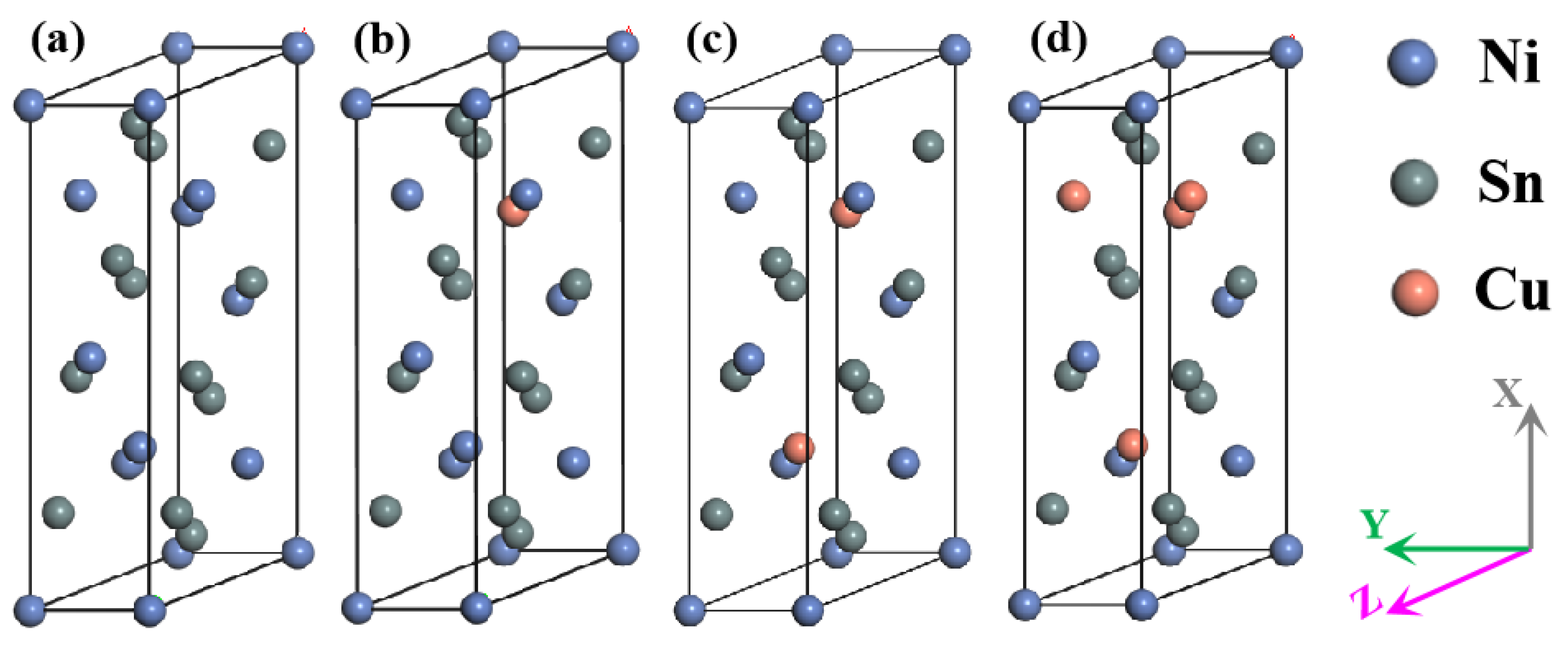
Figure 2.
The variation of the heat of formation (ΔH, meV/atom) with the Cu atom fraction.
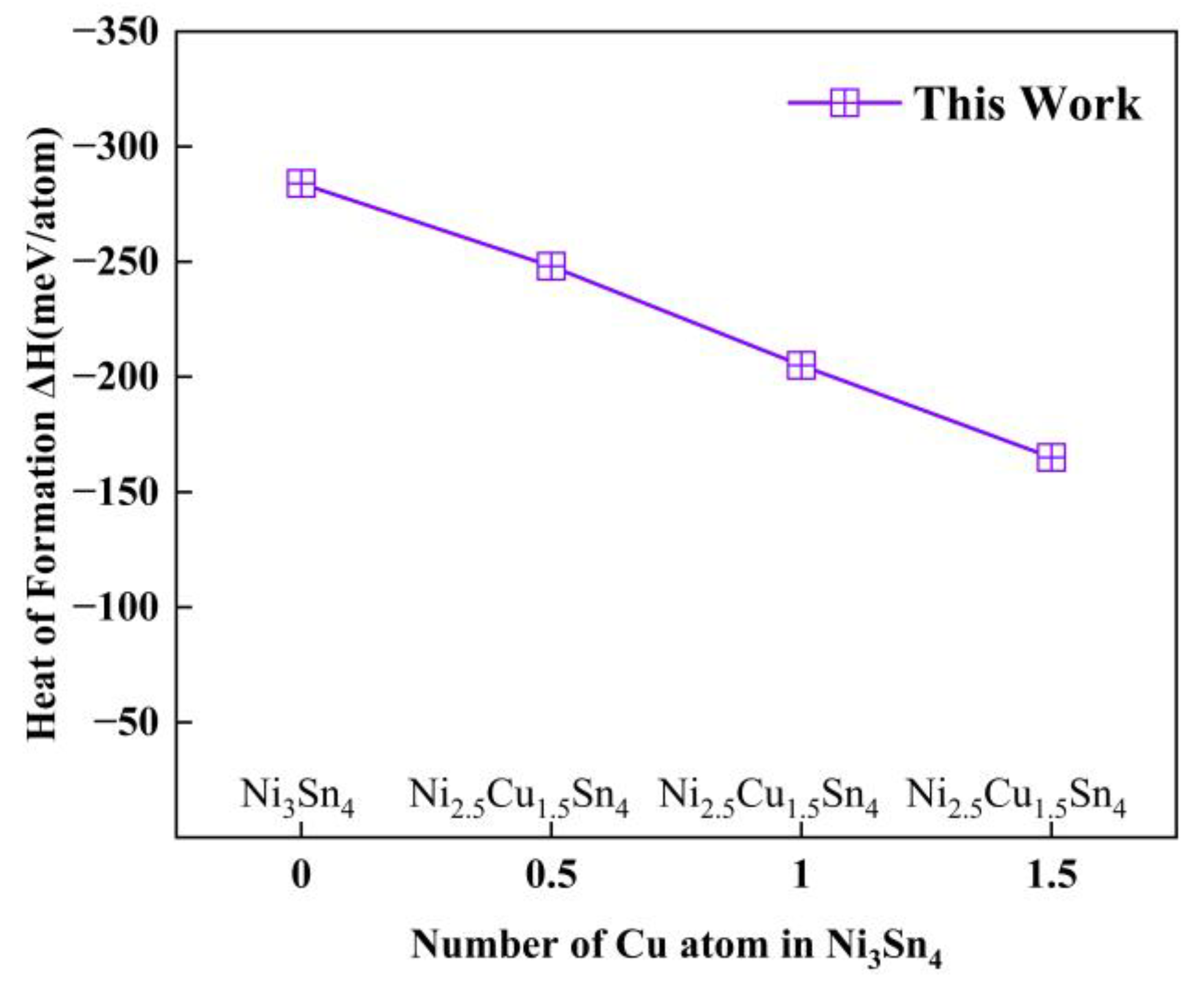
Figure 3.
The variation of bulk modulus, shear modulus, and Young modulus with the Cu atom fraction.
Figure 3.
The variation of bulk modulus, shear modulus, and Young modulus with the Cu atom fraction.
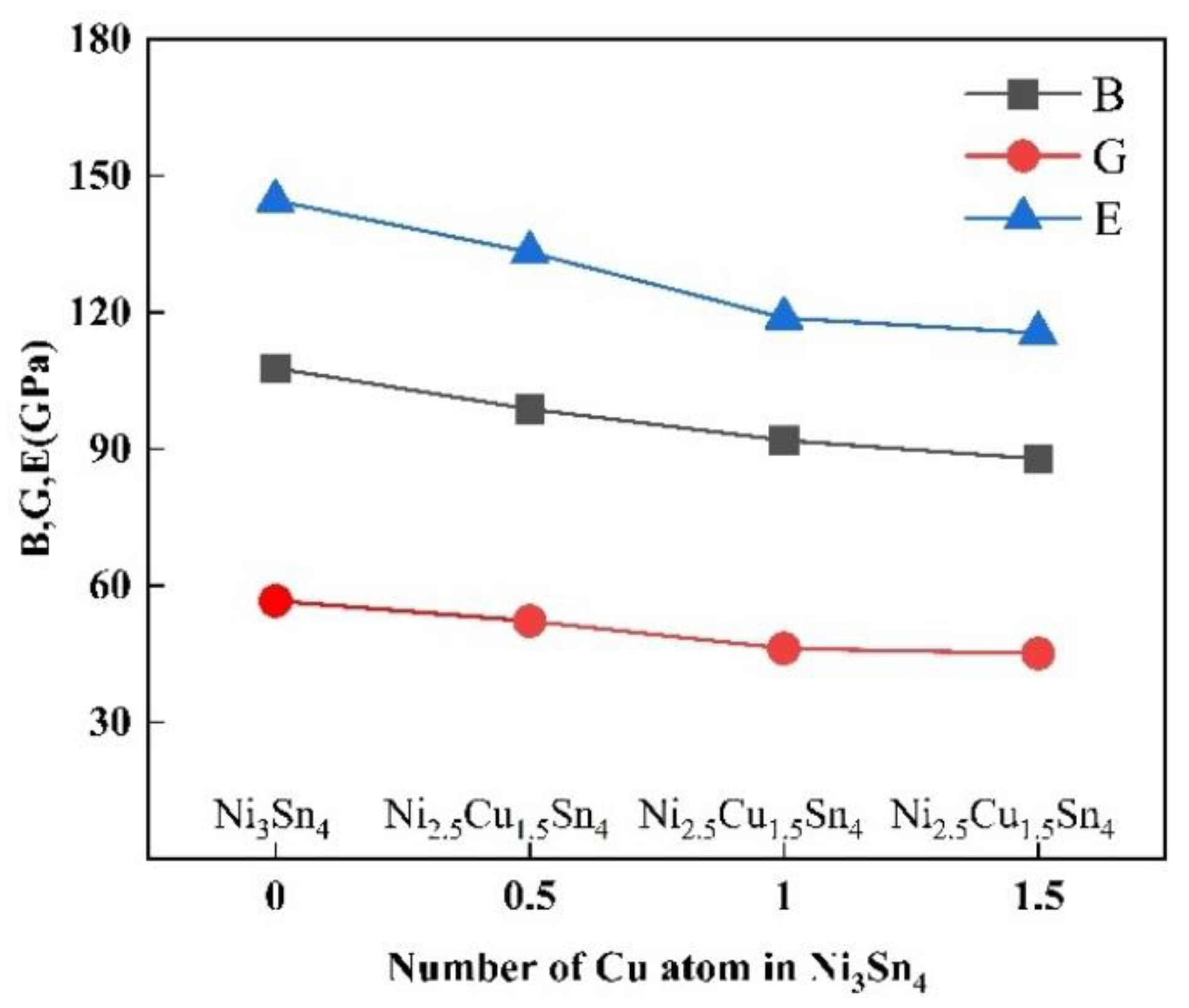
Figure 4.
The variation of ν, AU, and B/G with the Cu atom fraction.

Figure 5.
The surface constructions of bulk modulus for (a) Ni3Sn4, (b) Ni2.5Cu0.5Sn4, (c) Ni2.0Cu1.0Sn4, (d) Ni1.5Cu1.5Sn4.
Figure 5.
The surface constructions of bulk modulus for (a) Ni3Sn4, (b) Ni2.5Cu0.5Sn4, (c) Ni2.0Cu1.0Sn4, (d) Ni1.5Cu1.5Sn4.

Figure 6.
The surface constructions of Young modulus for (a) Ni3Sn4, (b) Ni2.5Cu0.5Sn4, (c) Ni2.0Cu1.0Sn4, (d) Ni1.5Cu1.5Sn4.
Figure 6.
The surface constructions of Young modulus for (a) Ni3Sn4, (b) Ni2.5Cu0.5Sn4, (c) Ni2.0Cu1.0Sn4, (d) Ni1.5Cu1.5Sn4.

Figure 7.
TDOS and PDOS for (a) Ni3Sn4, (b) Ni2.5Cu0.5Sn4, (c) Ni2.0Cu1.0Sn4, (d) Ni1.5Cu1.5Sn4.

Table 1.
The lattice constants a, b and c (Å), angle β (°) and the heat of formation (ΔH, meV/atom) of Ni3Sn4, Ni2.5Cu0.5Sn4, Ni2.0Cu1.0Sn4, and Ni1.5Cu1.5Sn4 obtained from Refs. [26,27,32,33] and this paper.
| Phases | Reference | a | b | c | β | ΔH |
|---|---|---|---|---|---|---|
| Ni3Sn4 | This work | 12.323 | 4.119 | 5.303 | 105.416 | −284 |
| [26] | 12.299 | 4.084 | 5.288 | 105.190 | −260 | |
| [32] | 12.418 | 4.111 | 4.315 | 105.480 | −267 | |
| [33] | 12.334 | 4.100 | 5.325 | 105.010 | −269 | |
| Ni2.5Cu0.5Sn4 | This work | 12.419 | 4.146 | 5.291 | 105.555 | −248 |
| [26] | 12.357 | 4.102 | 5.307 | 105.150 | −219 | |
| [32] | 12.426 | 4.101 | 5.363 | 105.690 | −193 | |
| Ni2.0Cu1.0Sn4 | This work | 12.434 | 4.149 | 5.365 | 105.541 | −205 |
| [26] | 12.420 | 4.128 | 5.331 | 105.150 | −179 | |
| [27] | 12.422 | 4.133 | 5.331 | 105.160 | −188 | |
| Ni1.5Cu1.5Sn4 | This work | 12.538 | 4.173 | 5.382 | 105.958 | −165 |
| [26] | 12.495 | 4.145 | 5.381 | 105.16 | −135 | |
| [27] | 12.507 | 4.146 | 5.382 | 105.07 | −144 |
Table 2.
The calculated elastic constants Cij (GPa) for Ni3Sn4, Ni2.5Cu0.5Sn4, Ni2.0Cu1.0Sn4, and Ni1.5Cu1.5Sn4 obtained from Refs. [26,32,33] and this paper.
| Phases | Reference | C11 | C12 | C13 | C22 | C23 | C33 | C44 | C55 | C66 | C15 | C25 | C35 | C46 |
|---|---|---|---|---|---|---|---|---|---|---|---|---|---|---|
| Ni3Sn4 | This work | 165.96 | 74.58 | 72.13 | 183.59 | 68.85 | 191.67 | 62.35 | 64.28 | 55.35 | −17.26 | 12.83 | −5.70 | 9.67 |
| [26] | 176.60 | 64.30 | 57.40 | 146.00 | 76.10 | 169.70 | 60.80 | 49.50 | 46.70 | −22.90 | 7.00 | −9.60 | 6.90 | |
| [32] | 155.48 | 70.68 | 69.34 | 164.33 | 68.26 | 149.86 | 62.74 | 59.99 | 59.95 | −21.97 | 13.99 | −8.73 | 4.90 | |
| [33] | 153.09 | 68.22 | 63.25 | 144.31 | 75.37 | 176.53 | 57.42 | 57.35 | 53.84 | −22.70 | 12.94 | −11.11 | 9.09 | |
| Ni2.5Cu0.5Sn4 | This work | 153.70 | 67.24 | 63.10 | 165.94 | 63.53 | 186.08 | 48.84 | 59.64 | 57.98 | −21.22 | 12.00 | −4.30 | 9.61 |
| [32] | 146.95 | 71.79 | 64.07 | 176.30 | 73.29 | 154.47 | 57.86 | 55.11 | 55.41 | −21.79 | 11.93 | −6.18 | 8.22 | |
| Ni2.0Cu1.0Sn4 | This work | 138.64 | 63.51 | 62.15 | 156.72 | 60.21 | 166.06 | 45.23 | 47.76 | 56.05 | −20.92 | 10.26 | −4.43 | 8.55 |
| Ni1.5Cu1.5Sn4 | This work | 134.58 | 53.68 | 59.37 | 146.62 | 69.75 | 148.91 | 54.13 | 40.93 | 55.57 | −14.66 | 8.82 | −4.51 | 7.93 |
Table 3.
The calculated bulk modulus (B, GPa), shear modulus (G, GPa), Young modulus (E, GPa) and Poisson ratio (ν) for Ni3Sn4, Ni2.5Cu0.5Sn4, Ni2.0Cu1.0Sn4, and Ni1.5Cu1.5Sn4 obtained from Refs. [23,26,27,32,33] and this paper.
| Phases | Reference | B | G | E | ν | B/G |
|---|---|---|---|---|---|---|
| Ni3Sn4 | This work | 107.78 | 56.64 | 144.59 | 0.276 | 1.90 |
| [23] | 102.10 | 54.10 | 127.20 | 0.250 | 1.89 | |
| [26] | 97.90 | 49.08 | 126.11 | 0.285 | 2.00 | |
| [32] | 98.01 | 53.96 | 136.78 | 0.287 | 1.82 | |
| [33] | 98.30 | 49.27 | 126.65 | 0.290 | 2.00 | |
| Ni2.5Cu0.5Sn4 | This work | 98.79 | 52.23 | 133.21 | 0.275 | 1.89 |
| [27] | 94.25 | 49.07 | 125.43 | 0.278 | 1.92 | |
| [32] | 98.45 | 49.62 | 127.45 | 0.284 | 1.95 | |
| Ni2.0Cu1.0Sn4 | This work | 91.93 | 46.24 | 118.80 | 0.285 | 1.99 |
| Ni1.5Cu1.5Sn4 | This work | 87.84 | 45.08 | 115.48 | 0.281 | 1.95 |
Table 4.
The calculated bulk modulus (GPa) and shear modulus (Gpa) in VRH approximations and the universal anisotropy index (AU) for Ni3Sn4, Ni2.5Cu0.5Sn4, Ni2.0Cu1.0Sn4, and Ni1.5Cu1.5Sn4 obtained from Refs. [32,33] and this paper.
| IMCs | Reference | GV | GR | BV | BR | GV/GR | BV/BR | AU |
|---|---|---|---|---|---|---|---|---|
| Ni3Sn4 | This work | 58.11 | 55.17 | 108.04 | 107.53 | 1.053 | 1.005 | 0.271 |
| [32] | 53.96 | 49.42 | 98.47 | 97.56 | 1.092 | 1.001 | 0.461 | |
| [33] | 51.79 | 46.74 | 99.07 | 97.53 | 1.108 | 1.016 | 0.556 | |
| Ni2.5Cu0.5Sn4 | This work | 54.08 | 50.38 | 99.27 | 98.31 | 1.077 | 1.010 | 0.378 |
| [32] | 51.58 | 47.66 | 99.56 | 97.33 | 1.082 | 1.013 | 0.423 | |
| Ni2.0Cu1.0Sn4 | This work | 48.18 | 44.30 | 92.57 | 91.28 | 1.088 | 1.014 | 0.454 |
| Ni1.5Cu1.5Sn4 | This work | 46.61 | 43.54 | 88.41 | 87.26 | 1.071 | 1.013 | 0.366 |
Disclaimer/Publisher’s Note: The statements, opinions and data contained in all publications are solely those of the individual author(s) and contributor(s) and not of MDPI and/or the editor(s). MDPI and/or the editor(s) disclaim responsibility for any injury to people or property resulting from any ideas, methods, instructions or products referred to in the content. |
© 2024 by the authors. Licensee MDPI, Basel, Switzerland. This article is an open access article distributed under the terms and conditions of the Creative Commons Attribution (CC BY) license (https://creativecommons.org/licenses/by/4.0/).
Share and Cite
MDPI and ACS Style
Yao, J.; Wang, L.; Guo, S.; Li, X.; Chen, X.; Shang, M.; Ma, H.; Ma, H. First-Principles Study of Cu Addition on Mechanical Properties of Ni3Sn4-Based Intermetallic Compounds. Metals 2024, 14, 64. https://doi.org/10.3390/met14010064
AMA Style
Yao J, Wang L, Guo S, Li X, Chen X, Shang M, Ma H, Ma H. First-Principles Study of Cu Addition on Mechanical Properties of Ni3Sn4-Based Intermetallic Compounds. Metals. 2024; 14(1):64. https://doi.org/10.3390/met14010064
Chicago/Turabian StyleYao, Jinye, Li Wang, Shihao Guo, Xiaofu Li, Xiangxu Chen, Min Shang, Haoran Ma, and Haitao Ma. 2024. "First-Principles Study of Cu Addition on Mechanical Properties of Ni3Sn4-Based Intermetallic Compounds" Metals 14, no. 1: 64. https://doi.org/10.3390/met14010064
Note that from the first issue of 2016, this journal uses article numbers instead of page numbers. See further details here.