
Microstructure and Mechanical Properties of Friction Stir Lap Welding Joint of Al/CU Dissimilar Metals

1
Key Laboratory of Automobile Materials of Ministry of Education, School of Materials Science and Engineering, Jilin University, Changchun 130025, China
2
Key Laboratory of Advanced Structural Materials, Ministry of Education, Changchun University of Technology, Changchun 130012, China
*
Authors to whom correspondence should be addressed.
Metals 2023, 13(12), 1969; https://doi.org/10.3390/met13121969
Submission received: 24 October 2023
/
Revised: 28 November 2023
/
Accepted: 30 November 2023
/
Published: 3 December 2023
(This article belongs to the Topic Development of Friction Stir Welding and Processing)
Abstract
:In this paper, 5083 aluminum alloy and T2 copper were selected for the friction stir lap welding test. The effect of intermetallic compounds on the microstructure and properties of Al/Cu dissimilar metal lap joints was studied. The results showed that the circulating Al/Cu composite structure was formed on the advancing side of the lap joint, and the Al/Cu staggered hook-like structure and copper-rich region were generated on the retreating side. There was no typical ‘onion ring’ structure in the joint. Element diffusion occurred at the interface of the joint, forming a thin and uniform interfacial layer of Al/Cu intermetallic compounds, thus achieving a well-metallurgical bond at the Al/Cu interface. There were the intermetallic compounds Al2Cu and Al4Cu9, without AlCu, in the lap joint. In addition, dynamic recrystallization occurred in the nugget zone, and higher dislocation density and dislocation entanglement were generated, which enhanced the deformation resistance in the nugget zone and increased the joint strength. The tensile test showed that the ductile–brittle mixed fracture occurred in the heat-affected zone on the advancing side of the aluminum plate, and the fracture had necking. The failure load of the lap joint was 4350 ± 30 N, about 80% of the aluminum base metal. The elongation of the Al/Cu dissimilar lap joint tensile specimen was 2.5%.
1. Introduction
Aluminum and copper have good thermal conductivity, electrical conductivity, and corrosion resistance, which have been widely used in various industries of the national economy. However, the high density of copper hinders its application in industrial lightweight design, and the relatively small resource reserve also leads to expensive production costs. While the density of aluminum is low and the mineral resources are abundant. Aluminum and its alloys can replace copper in industrial production to prepare aluminum–copper composite structures, which save costs and conform to a lightweight design [1,2,3]. The aluminum–copper composite structure combines the excellent properties of both materials while reducing the amount of copper used and lowering industrial production costs [2,4,5]. Due to the significant differences in physical and chemical properties, such as the melting point and the linear expansion coefficient of aluminum and copper, welding defects such as solidification cracks, pores, and intermetallic compounds will be generated when the conventional welding methods are used, resulting in a decrease in the performance of Al/Cu lap joints [6,7].
Friction stir welding is an environmentally friendly solid-state joining technology with significant advantages, which can be applied to butt and lap welding of identical or dissimilar metals [8,9,10]. This technique has better production efficiency than conventional welding methods and functions at a lower temperature than the melting point of the metal. It enables the prevention of welding defects, limits metallurgical reactions, and reduces the formation of intermetallic compounds [11,12]. As a result, friction stir welding technology has been utilized in various industries, such as petrochemical, nuclear, and aerospace, as well as in other developing industries [13,14,15,16].
Over the past few years, numerous scholars have been engaged in the field of friction stir welding technology of aluminum and copper dissimilar metals. Galvão et al. [17] investigated the impact of shoulder geometry on the distribution and formation of intermetallic compounds when performing friction stir welding on aluminum–copper alloys. They discovered that the conical tool led to a mixture of aluminum, copper, Al2Cu, and Al4Cu9, with a lower intermetallic content. Marstatt et al. [18] investigated the mechanism of intermetallic compound formation at the joint interface and its relationship with temperature using commercially pure alloys ENAW-1050 and CW008A. The study revealed that the thickness of the intermetallic layer correlated with the process temperature and was generated by interdiffusion. Choudhury et al. [19] studied the microstructure and mechanical properties of AA 6061-T6 and pure copper lap joints at different welding and rotational speeds. They concluded that the formation of intermetallic compounds was responsible for lower failure stresses in joints welded at lower speeds. Ouyang et al. [20] investigated the temperature distribution and microstructure evolution during the friction stir welding process of 6061 aluminum alloy and copper. The study determined that the poor mechanical properties of the joints were attributed to various brittle intermetallic compounds formed in the nugget zone. However, Xue et al. [21] reported that a thin, continuous, and homogeneous intermetallic compound layer was beneficial for improving the tensile and flexural strength of joints, and the appropriate thickness of the intermetallic compound layer was around 1 μm. Muthu et al. [22] obtained an Al/Cu butt joint with an intermetallic compound thickness of 1.9 μm by friction stir welding, and the tensile strength efficiency reached 70% of the base metal. Shankar et al. [23] successfully fabricated AA1050 and oxygen-free copper (Cu-OF) joints with dissimilar thicknesses by friction stir welding. Their research indicated that the highest tensile strength was 91% of the AA1050 alloy strength, with the tensile fracture path on the AA1050 Al side. A layer containing Al2Cu and Al4Cu9 intermetallic compounds with a thickness of 2.2 μm to 0.26 μm was formed at the interface of the Al/Cu joint. The properties of the joint are affected by the varying thickness of the intermetallic layer, and the voluminous intermetallic compounds were found to affect the tensile properties of the joint.
As mentioned above, the studies on the intermetallic compounds of Al/Cu dissimilar metal friction stir welding have focused mainly on the butt weld shape, and studies on the lap weld shape are rarely reported. Al/Cu thin plate lap welding has significant application value in new energy vehicle battery manufacturing and radiator welding. To clarify the effect of intermetallic compounds formed during the lap welding process on the strength of the lap joint and to provide a reference for the study and industrial application of friction stir welding of aluminum and copper dissimilar materials, the microstructure of the nugget zone and the interface of the lap joint fabricated by friction stir welding for 5083 aluminum alloy and T2 copper were investigated in detail.
2. Experimental Procedures
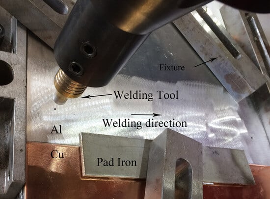
In the study, 5083 aluminum alloy and T2 copper plates were selected for testing. The dimensions were 200 mm × 150 mm × 2 mm and 200 mm × 150 mm × 3 mm, respectively. The chemical compositions and thermophysical parameters of the base metals are shown in Table 1 and Table 2. All the lap joints were fabricated with the FSW-LM-XL16-2D friction stir welding machine. The welding process schematic is shown in Figure 1. The welding tool was made of H13 steel with a concave shoulder diameter of 12 mm in 3° concavity. The stirring pin was a round table with a right-hand thread structure, root diameter Φ1 = 6 mm, end diameter Φ2 = 3 mm, and pin length 3 mm. During the friction stir welding process, the rotational speed was 900 r/min, the welding speed was 60 mm/min, the tilt angle was 2.5°, and the plunge depth was 0.1 mm. Before welding, T2 copper was heated to 650 °C held at this temperature for 1 h, and then annealed with air cooling. The purpose of these steps was to soften T2 copper and to decrease the hardness of the base metal. After welding, the metallographic and tensile specimens were prepared perpendicular to the welding direction using a discharge cutting machine. The size of the metallographic sample was 16 mm × 16 mm × 5 mm, and the cross-section of the lap joint was ground and polished.
The cross-section microstructure of the aluminum–copper lap joint was characterized by a TESCAN-VEGA3 Scanning Electron Microscope (SEM, Tescan Orsay Holding, Brno, Czech Republic) to obtain the cross-section microstructure of the lap joint. The phase composition of the cross-section of the lap joint was analyzed by D/MAX2000/PC X-ray diffraction (XRD, Rigaku, Tokyo, Japan). The EDAX Falcon Energy Dispersive Spectrometer (EDS, EDAX Inc., UT, USA) was used to analyze the chemical composition and element distribution at the interface of the lap joint. The tensile test was carried out by a WES2000 tensile testing machine (Changchun Kexin Test Instrument Co., Ltd., Changchun, China). The schematic diagram of the tensile specimen is shown in Figure 2. All tests were performed at a constant strain rate of 2 mm/min. The tensile shear force and failure position were tested two times. The SEM was utilized to probe the primary fracture mechanism of the lap joints. The microhardness of the lap joint was measured using the FM700 hardness testing machine (Future-Tech Corp. Kanagawa, Kawaki, Japan). The test load was 100 g, and the loading time was 15 s.
In the copper-rich region shown in Figure 3a and Figure 4a, the sample was taken and cut into thin sections, and the cut sections were ground and polished until the sample was ground into a metal sheet with a thickness of 0.05 mm. The sample sheet was punched into a circle with a diameter of 3 mm by a puncher, and then, the sample was nailed thin. Finally, the sample was thinned using an ion thinning instrument to obtain a transmission electron microscope (TEM) sample. The phase composition of the copper-rich region was further analyzed using a JEM-2000DX transmission electron microscope machine (JEOL Ltd., Tokyo, Japan).
3. Results and Discussion
3.1. Interfacial Characteristic
Figure 3a is the macro morphology image of the lap joint cross-section. From Figure 3a, it can be seen that the hook-like structure and copper-rich zone are formed on the retreating side of the lap joint, the aluminum–copper composite structure is formed on the advancing side, and there is microporosity at the interface of the lap joint. Figure 3b is the weld morphology image of the lap joint. From Figure 3b, it can be seen that the weld surface is well-formed, but a few of flashes and burrs appear at the end of the weld. This is because, with the progress of friction stir welding, the heat generated during the welding process was transferred to the rear part of the base metal, which played a role in preheating and improving the plasticity and fluidity of the base metal at the rear of the weld, and the plasticized base metal overflowed under the action of the rotation-upset forging of the stirring tool, forming flashes and burrs.
Figure 4a is the backscattered SEM image at the cross-section of the lap joint sample shown in Figure 3a. As shown in Figure 4a, there are zigzag structures and microporosity at the interface of the lap joint. A circulating Al/Cu composite structure was formed on the advancing side, and an Al/Cu staggered hook-like structure and copper-rich region were generated on the retreating side. Figure 4b shows the magnified image of the hook-like structure. Al and Cu were interlaced to form a hook-like structure surrounded by microporosity. The hook-like structure tended to extend towards the advancing side. It was due to the formation of a transient cavity on the rear side of the stirring pin during the friction stir welding, and the base metal on the retreating side will transfer from the back side of the pin to the advancing side, resulting in the formation of a hook-like structure [24,25]. A hook-like structure is an unavoidable defect in friction stir lap welding of dissimilar metals with varying hardness and a deeper plunge depth of the stirring pin [26]. Studies indicated that a hook-like structure can considerably enhance the interface bonding area and increase the tensile and shear properties of the joint. However, brittle and intermetallic compounds are easily generated around the hook-like structure, which makes it easy to produce holes, cracks, and other welding defects. They act as crack sources in tensile tests and reduce the mechanical properties of the lap joint [27,28].
In Figure 4c, copper is distributed in an island or strip shape in the upper aluminum matrix to form a copper-rich region, which can be considered an aluminum matrix composite. The distribution of copper in various forms within the aluminum matrix was attributed to the function of the stirring-upset forging influence of the stirring tool. During the welding, the friction heat generated by the high-speed rotation of the shoulder made the aluminum reach a plastic flow state, and the heat was transmitted to the lower layer of copper to soften it. Under the action of the stirring tool, the aluminum was transferred to the retreating side and below the interface, and the copper was migrated into the aluminum and squeezed into an island-like structure. Part of the copper at the edge of the interface was stripped from the matrix under the action of shear force and distributed in the form of strips or blocks in the upper aluminum layer [29]. In addition, a zigzag structure is formed at the interface under the action of the stirring pin, as shown in Figure 4d, which effectively enhances the bonding area of the aluminum and copper interface.
Since the joint geometry used in this study was a lap joint, the shoulder of the stirring tool acted directly on the upper aluminum plate during the welding process, the stirring effect on the copper plate was limited, and the welding heat input was low. As a result, the two base metals of aluminum and copper were mixed insufficiently in the weld nugget zone. Thus, the nugget zone of the lap joint did not form a typical ‘onion ring’ structure. The plastic deformation and plastic flow of the base metal in the nugget zone were insufficient, which led to the accumulation of Cu on the retreating side [30]. However, the partially plastically flowing aluminum and copper are alternately distributed on the advancing side under the action of a stirring pin to form a circulating aluminum–copper composite structure, as shown in Figure 4e, which indicates the existence of mechanical and metallurgical hybrid bonding in the lap joint [31].
3.2. Interfacial Elements and Phase Distribution
Figure 5 shows the XRD analysis results of the cross-section of the lap joint, and Figure 6 shows the TEM test results of the copper-rich region of the lap joint and the corresponding SAED images. The XRD results showed that the intermetallic compounds formed in the lap joint were Al2Cu and Al4Cu9. Moreover, the TEM analysis also revealed the presence of intermetallic compounds in the lap joint, which correlated to the XRD analyses. The crystallographic analysis shows that the more atoms in the crystal cell, the more unfavorable it is for crystallization. The crystal cell of Al2Cu has 12 atoms, while Al4Cu9 has 52 atoms. Therefore, Al2Cu has the lowest diffusion activation energy and preferentially nucleates during the bonding process. The formation of Al4Cu9 is caused by the thermal-mechanically induced solid-state diffusion process [32]. Ouyang et al. [20] pointed out that the chemical reaction during the thermal cycle of the friction stir welding process did not reach the equilibrium condition. The formation of intermetallic compounds could not be understood solely based on the Al/Cu phase diagram. It is assumed that the bonding of Al in the Cu matrix during friction stir welding is a mechanical bonding process. The material in the stir zone undergoes severe plastic deformation under the action of the stirring pin, the atomic diffusion rate in the stir zone increases, and the atom concentration reaches the favorable condition for forming Al4Cu9. Eventually, the intermetallic compound Al4Cu9 is generated under the combined action of the welding heat input and the stirring pin.
In the above test results, AlCu was not present in the lap joint, which was inconsistent with the findings of Abdollah-Zadeh A et al. [33] that AlCu, Al2Cu, and Al4Cu9 are the main intermetallic compounds formed during the Al/Cu friction stir welding. This is due to the structural transformation of AlCu during the welding process to generate Al4Cu9. The research [34] indicated that for copper-rich mixtures, solid solutions of aluminum in copper and Al4Cu9 are formed by consuming Cu, Al, AlCu, and Al2Cu. In addition, due to the consumption of AlCu, the decrease in its concentration in the sample could not be effectively identified.
Figure 7a is the high-magnification image of region B in Figure 4a. In Figure 7a, an EDS point scanning analysis was performed in test points A and B, respectively. The mass fraction of aluminum in area A was 65.59%, and the mass fraction of copper was 34.41%. The mass fraction of aluminum in area B was 21.87%, and the mass fraction of copper was 78.13%. Figure 7b shows the EDS line scanning results at the interface. The elemental diffusion occurred at the joint interface, and the thickness of the interfacial layer was 5.46 μm. Combined with the XRD, TEM results, and Al/Cu phase diagram, the region of the test point A was the aluminum-rich phase Al2Cu, and the region B was the copper-rich phase Al4Cu9, indicating that the interface layer was composed of the intermetallic compounds Al2Cu and Al4Cu9. This was consistent with the results of Xue et al. [24] and Genevois et al. [35].
3.3. Microhardness Analysis
Figure 8a shows the microhardness curves parallel to the lap joint interface, at 1 mm above and below. The hardness of the nugget zone increased sharply. Firstly, dynamic recrystallization and grain refinement occurred in the nugget zone under the action of the stirring pin [36]. Secondly, as shown in Figure 6b, due to the severe plastic deformation that occurred in the weld nugget zone under the action of the stirring tool, there was higher dislocation density and dislocation entanglement in the nugget zone, which led to the increase in deformation resistance and hardness of the nugget zone [31]. Thirdly, there were hard, brittle intermetallic compounds with higher hardness values in the lap joint, resulting in the increased hardness of the nugget zone.
Figure 8b shows the microhardness curves measured perpendicular to the interface. The microhardness of the retreating side of the aluminum side was higher than that of the advancing side, and the microhardness of the interface to the copper side increased first and then decreased. According to the study of Hsu et al. [37], the finer grain size in the matrix and the Orowan strengthening caused by the dispersion of fine intermetallic compounds were the main reasons for the high strength of the composite structure. During the welding process, the aluminum base metal in the nugget zone underwent dynamic recrystallization and grain refinement under the action of the stirring pin. Copper migrated to the retreating side of the lap joint to form a hook-like structure and a copper-rich region, and intermetallic compounds were generated in this zone. Therefore, the microhardness of the retreating side was higher than that of the advancing side. In addition, dynamic recrystallization occurred in the nugget zone on the copper side, generating dense and finer equiaxed grains [38]. As a result, the microhardness values increased initially and then declined gradually as the testing point moved farther from the interface.
3.4. Tensile Shear Performance of Lap Joints
The stress–strain curve of the lap joint tensile specimen is illustrated in Figure 9. It can be seen from the diagram that the AB section curve indicates that the tensile specimen is in the elastic deformation stage. When the yield limit of the lap joint is reached, the tensile specimen undergoes plastic deformation (as shown in the BC section curve). During the friction stir lap welding of aluminum–copper dissimilar metals, the stirring tool did not completely pass through the aluminum and copper base metals in the thickness direction. As a result, the effective lap area in the lap joint cannot be accurately obtained, so the tensile strength of the lap joint cannot be accurately obtained. Therefore, the tensile shear force was used to characterize the tensile properties of the lap joint. The results from the tensile test demonstrate that under an increasing tensile load, the lap joint failed and broke upon reaching a tensile shear force of 4350 ± 30 N with an elongation value of 2.5%.
Figure 10a shows that the fracture position of the lap joint is the heat-affected zone on the advancing side of the aluminum plate, rather than the thinning position of the aluminum plate above the hook-like structure. The fracture position of the joint had a certain necking, which indicates that plastic deformation occurs before the fracture of the tensile specimen, and the material exhibited ductile fracture characteristics. From Figure 4c, the thickness of the aluminum plate above the hook-like structure is significantly reduced. However, due to the formation of the thin and uniform intermetallic compound layers in the joint, the adverse effect of the plate thinning on the mechanical properties was offset. The heat-affected zone underwent grain growth with thermal cycling, leading to failure in the heat-affected zone with the lowest hardness value [19]. Figure 10b presents the morphology of the tensile fracture. There were plenty of dimples and river pattern areas in the fracture. Figure 10c exhibits a high-magnification image of the river pattern area, which shows a tearing shape under the tensile load. Figure 10d is a high-magnification image of the dimples. Since the Al alloy is a face-centered cubic structure, there are more plastic slip systems, and it is easy to have multi-slip systems. As a consequence, there were deep dimples and sharp tearing edges in the fracture, along with plastic deformation characteristics. In summary, the fracture mode of the lap joint was a ductile–brittle mixed fracture.
The failure load of the lap joint was 4350 ± 30 N, which was approximately 80% of the aluminum strength. Firstly, the copper particles in the copper-rich region and the intermetallic compounds generated around them were distributed in the Al matrix, forming an aluminum matrix composite. According to the dispersion strengthening mechanism, the hard particles hinder the dislocation movement during plastic deformation, thus improving the bonding strength of the lap joint. Secondly, there was a thin and uniform intermetallic compounds layer at the joint interface with a thickness of 5.46 µm. The study [21] showed that the thin and uniform intermetallic compound layer can effectively improve the bonding strength of the joint.
4. Conclusions
A circular Al/Cu composite structure was formed on the advancing side, and an Al/Cu staggered hook-like structure and a copper-rich zone were generated on the retreating side. There was no typical ‘onion ring’ structure in the joint, and there were zigzag structures and microporosity at the interface. Element diffusion occurred at the joint interface. A thin and uniform interface layer with a thickness of 5.46 μm was formed. The lap joint contained the intermetallic compounds Al2Cu and Al4Cu9 without AlCu. The formation of intermetallic compounds in the lap joint, dynamic recrystallization in the nugget zone, grain refinement, and formation of higher dislocation density and dislocation entanglement led to increased deformation resistance in the nugget zone and a higher joint strength. The failure load of the lap joint was 4350 ± 30 N, which was about 80% of the 5083 Al base material. The fracture area was the heat-affected zone on the advancing side of the aluminum plate. The fracture had necking, and the elongation of the Al/Cu dissimilar lap joint tensile specimen was 2.5%. The fracture mode was a ductile–brittle mixed fracture.
Author Contributions
Conceptualization, F.J. and W.G.; methodology, F.J.; formal analysis, F.J. and W.W.; investigation, F.J.; resources, W.W. and W.G.; data curation, F.J. and W.W.; writing—original draft preparation, F.J.; writing—review and editing, W.W., X.Z., and W.G.; supervision, W.W. and X.Z.; funding acquisition, W.W. All authors have read and agreed to the published version of the manuscript.
Funding
This research was funded by the Key Laboratory Fund for National Defense Science and Technology, China, grant number 6142005200301, and the Innovation Platform and Talent Project of Jilin Provincial Department of Science and Technology, grant number 20230508039RC.
Data Availability Statement
The data presented in this study are available on request from the corresponding author.
Acknowledgments
The authors thank Weijian Liu for his assistance with the experiments, which greatly contributed to this article.
Conflicts of Interest
The authors declare no conflict of interest.
References
- He, H.; Liu, Z.; Zhu, Y.; Chu, J.; Li, S.; Pei, S.; Zhang, C.; Fu, A.; Zhao, W. Mechanism of pin thread and flat features affecting material thermal flow behaviours and mixing in Al-Cu dissimilar friction stir welding. Int. J. Mech. Sci. 2023, 260, 108615. [Google Scholar] [CrossRef]
- You, J.; Zhao, Y.; Dong, C.; Su, Y. Improving the microstructure and mechanical properties of Al-Cu dissimilar joints by ultrasonic dynamic-stationary shoulder friction stir welding. J. Mater. Process. Technol. 2023, 311, 117812. [Google Scholar] [CrossRef]
- Elmetwally, H.T.; Abdelhafiz, M.A.; El-Sheikh, M.N.; Abdullah, M.E. Effect of friction stir-welding tool pin geometry on the characteristics of Al-Cu joints. Appl. Eng. Lett. J. Eng. Appl. Sci. 2023, 8, 60–69. [Google Scholar] [CrossRef]
- Sun, Y.; Gong, W.; Feng, J. A Review of the Friction Stir Welding of Dissimilar Materials between Aluminum Alloys and Copper. Metals 2022, 12, 675. [Google Scholar] [CrossRef]
- Cao, F.; Li, J.; Hou, W.; Shen, Y.; Ni, R. Microstructural evolution and mechanical properties of the friction stir welded Al[sbnd]Cu dissimilar joint enhanced by post-weld heat treatment. Mater. Charact. 2021, 174, 110998. [Google Scholar] [CrossRef]
- Zhang, H.; Sun, S.L.; Liu, X.; Song, J.; Chen, X. Effect of Tool-Workpiece Relative Position on Microstructure and Mechanical Properties of Al-Cu Dissimilar Friction Stir Weld. J. Mater. Eng. Perform. 2021, 31, 2457–2465. [Google Scholar] [CrossRef]
- Hou, W.; Shen, Z.; Huda, N.; Oheil, M.; Shen, Y.; Jahed, H.; Gerlich, A.P. Enhancing metallurgical and mechanical properties of friction stir butt welded joints of Al–Cu via cold sprayed Ni interlayer. Mater. Sci. Eng. A 2021, 809, 140992. [Google Scholar] [CrossRef]
- Zhang, H.; Zhang, B.; Li, C.; Wang, Y.; Gao, Q. Strengthening characteristic and mechanism of AlCoCrFeNi high-entropy alloy particles for Al-Cu dissimilar friction stir lap welded joint. Mater. Charact. 2023, 203, 113153. [Google Scholar] [CrossRef]
- Isa, M.S.M.; Moghadasi, K.; Ariffin, M.A.; Raja, S.; bin Muhamad, M.R.; Yusof, F.; Jamaludin, M.F.; bin Yusoff, N.; Karim, M.S.B. Recent research progress in friction stir welding of aluminium and copper dissimilar joint: A review. J. Mater. Res. Technol. 2021, 15, 2735–2780. [Google Scholar] [CrossRef]
- Meng, X.; Huang, Y.; Cao, J.; Shen, J.; Santos, J.F.d. Recent progress on control strategies for inherent issues in friction stir welding. Prog. Mater Sci. 2021, 115, 100706. [Google Scholar] [CrossRef]
- Raj, A.; Pratap, K.J.; Ramesha, K.; Rout, I.S. Modelling, Temperature Analysis, and Mechanical Properties of Friction Stir Welding of Al-Cu Joints with Hardened OHNS Steel Tools. J. Mines Met. Fuels 2022, 70, 462–470. [Google Scholar] [CrossRef]
- Zhao, Y.; You, J.; Qin, J.; Dong, C.; Liu, L.; Liu, Z.; Miao, S. Stationary shoulder friction stir welding of Al–Cu dissimilar materials and its mechanism for improving the microstructures and mechanical properties of joint. Mater. Sci. Eng. A 2022, 837, 142754. [Google Scholar] [CrossRef]
- Mubiayi, M.P.; Akinlabi, E.T. Characterization of the intermetallic compounds in aluminium and copper friction stir spot welds. Mater. Today Proc. 2017, 4, 533–540. [Google Scholar] [CrossRef]
- Elmetwally, H.T.; SaadAllah, H.N.; Abd-Elhady, M.S.; Abdel-Magied, R.K. Optimum combination of rotational and welding speeds for welding of Al/Cu-butt joint by friction stir welding. Int. J. Adv. Manuf. Technol. 2020, 110, 163–175. [Google Scholar] [CrossRef]
- Ma, H.; Qin, G.L.; Geng, P.H.; Li, F.; Meng, X.M.; Fu, B.L. Effect of post-weld heat treatment on friction welded joint of carbon steel to stainless steel. J. Mater. Process. Technol. 2016, 227, 24–33. [Google Scholar] [CrossRef]
- Ji, F.; Xue, S.B.; Lou, J.Y.; Lou, Y.B.; Wang, S.Q. Microstructure and properties of Cu/Al joints brazed with Zn-Al filler metals. Trans. Nonferr. Met. Soc. China 2012, 22, 281–287. [Google Scholar] [CrossRef]
- Galvão, I.; Oliveira, J.C.; Loureiro, A. Formation and distribution of brittle structures in friction stir welding of aluminium and copper influence of shoulder geometry. Intermetallics 2012, 22, 122–128. [Google Scholar] [CrossRef]
- Marstatt, R.; Krutzlinger, M.; Luderschmid, J.; Zaeh, M.F.; Haider, F. Formation of a diffusion-based intermetallic interface layer in friction stir welded dissimilar Al-Cu lap joints. IOP Conf. Ser. Mater. Sci. Eng. 2017, 181, 012002. [Google Scholar] [CrossRef]
- Choudhury, T.; Ghorai, A.; Medhi, T.; Acharya, U.; Roy, B.S.; Saha, S.C. Study of microstructure and mechanical properties in friction stir welded aluminum copper lap joint. Mater. Today Proc. 2021, 46, 9474–9479. [Google Scholar] [CrossRef]
- Ouyang, J.; Yarrapareddy, E.; Kovacevic, R. Microstructural evolution in the friction stir welded 6061 aluminum alloy (T6-temper condition) to copper. J. Mater. Process. Technol. 2007, 172, 110–122. [Google Scholar] [CrossRef]
- Xue, P.; Xiao, B.L.; Ni, D.R.; Ma, Z.Y. Enhanced mechanical properties of friction stir welded dissimilar Al–Cu joint by intermetallic compounds. Mater. Sci. Eng. A 2010, 527, 5723–5727. [Google Scholar] [CrossRef]
- Muthu, M.F.X.; Jayabalan, V. Tool travel speed effects on the microstructure of friction stir welded aluminum–copper joints. J. Mater. Process. Technol. 2015, 217, 105–113. [Google Scholar] [CrossRef]
- Shankar, S.; Vilaça, P.; Dash, P.; Chattopadhyaya, S.; Hloch, S. Joint strength evaluation of friction stir welded Al-Cu dissimilar alloys. Measurement 2019, 146, 892–902. [Google Scholar] [CrossRef]
- Xue, P.; Xiao, B.; Wang, D.; Ma, Z. Achieving high property friction stir welded aluminium/copper lap joint at low heat input. Sci. Technol. Weld. Join. 2011, 16, 657–661. [Google Scholar] [CrossRef]
- Nandan, R.; DebRoy, T.; Bhadeshia, H.K.D.H. Recent advances in friction-stir welding—Process, weldment structure and properties. Prog. Mater Sci. 2008, 53, 980–1023. [Google Scholar] [CrossRef]
- Tavassolimanesh, A.; Nia, A.A. A new approach for manufacturing copper-clad aluminum bimetallic tubes by friction stir welding (FSW). J. Manuf. Processes 2017, 30, 374–384. [Google Scholar] [CrossRef]
- Wang, D.A.; Lee, S.C. Microstructures and failure mechanisms of friction stir spot welds of aluminum 6061-T6 sheets. J. Mater. Process. Technol. 2007, 186, 291–297. [Google Scholar] [CrossRef]
- Ji, S.D.; Wen, Q.; Li, Z.W. A novel friction stir diffusion bonding process using convex-vortex pin tools. J. Mater. Sci. Technol. 2020, 48, 23–30. [Google Scholar] [CrossRef]
- Saeid, T.; Abdollah-zadeh, A.; Sazgari, B. Weldability and mechanical properties of dissimilar aluminum-copper lap joints made by friction stir welding. J. Alloys Compd. 2010, 490, 652–655. [Google Scholar] [CrossRef]
- Zhang, W.; Shen, Y.; Yan, Y.; Guo, R. Dissimilar friction stir welding of 6061 Al to T2 pure Cu adopting tooth-shaped joint configuration: Microstructure and mechanical properties. Mater. Sci. Eng. A 2017, 690, 355–364. [Google Scholar] [CrossRef]
- Zhang, Q.Z.; Gong, W.B.; Liu, W. Microstructure and mechanical properties of dissimilar Al–Cu joints by friction stir welding. Trans. Nonferr. Met. Soc. China 2015, 25, 1779–1786. [Google Scholar] [CrossRef]
- Galvao, I.; Oliveira, J.C.; Loureiro, A.; Rodrigues, D.M. Formation and distribution of brittle structures in friction stir welding of aluminium and copper influence of process parameters. Sci. Technol. Weld. Join. 2011, 16, 681–689. [Google Scholar] [CrossRef]
- Abdollah-Zadeh, A.; Saeid, T.; Sazgari, B. Microstructural and mechanical properties of friction stir welded aluminum/copper lap joints. J. Alloys Compd. 2008, 460, 535–538. [Google Scholar] [CrossRef]
- Wang, L.L.; Munir, Z.A.; Holt, J.B. The combustion synthesis of copper aluminides. Metall. Trans. B 1990, 21, 567–577. [Google Scholar] [CrossRef]
- Genevois, C.; Girard, M.; Huneau, B.; Sauvage, X.; Racineux, G. Interfacial reaction during friction stir welding of Al and Cu. Metall. Mater. Trans. A 2011, 42, 2290–2295. [Google Scholar] [CrossRef]
- Jadidi, A.; Azhiri, R.B.; Baghdadchi, A.; Salmanibideskan, A. Lap joining of aluminum 5052 to copper by optimum friction stir spot welding process. Int. J. Adv. Manuf. Technol. 2022, 119, 7339–7352. [Google Scholar] [CrossRef]
- Hsu, C.J.; Chang, C.Y.; Kao, P.W.; Ho, N.J.; Chang, C.P. Al–Al3Ti nanocomposites produced in situ by friction stir processing. Acta Mater. 2006, 54, 5241–5249. [Google Scholar] [CrossRef]
- Sun, H.Y.; Zhou, Q.; Zhu, J.; Peng, Y. Analysis on the Fracture of Al-Cu Dissimilar Materials Friction Stir Welding Lap Joint. J. Mater. Eng. Perform. 2017, 26, 5715–5722. [Google Scholar] [CrossRef]
Figure 1.
Schematic diagram of Al/Cu friction stir lap welding.

Figure 2.
Schematic diagram of tensile specimen.
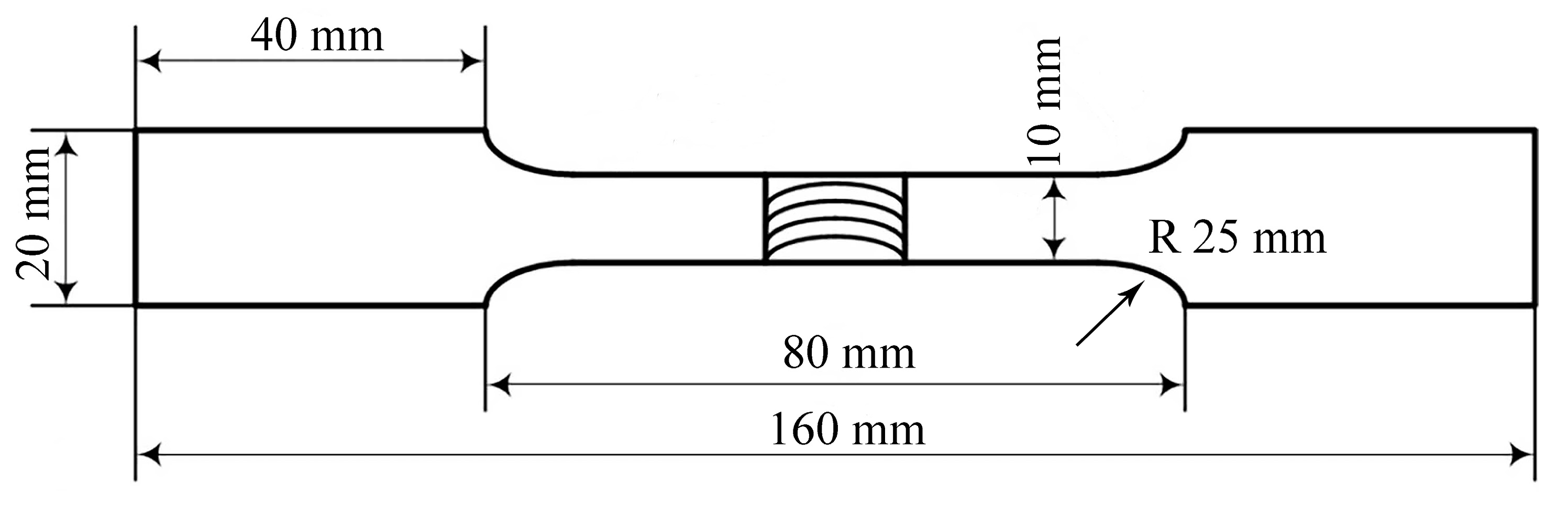
Figure 3.
(a) Macroscopic morphology of lap joint cross-section; (b) macroscopic morphology of lap joint weld.
Figure 3.
(a) Macroscopic morphology of lap joint cross-section; (b) macroscopic morphology of lap joint weld.

Figure 4.
The interface morphology of Al/Cu friction stir welding lap joint. (a) backscattered Scanning Electron Microscope (SEM) image of the lap joint cross-section; (b) magnified image of the hook-like structure; (c) magnified image of the copper-rich zone; (d) magnified image of the zigzag structure; (e) magnified image of the Al/Cu composite structure.


Figure 5.
X-ray diffraction (XRD) results at the cross-section of the lap joint.
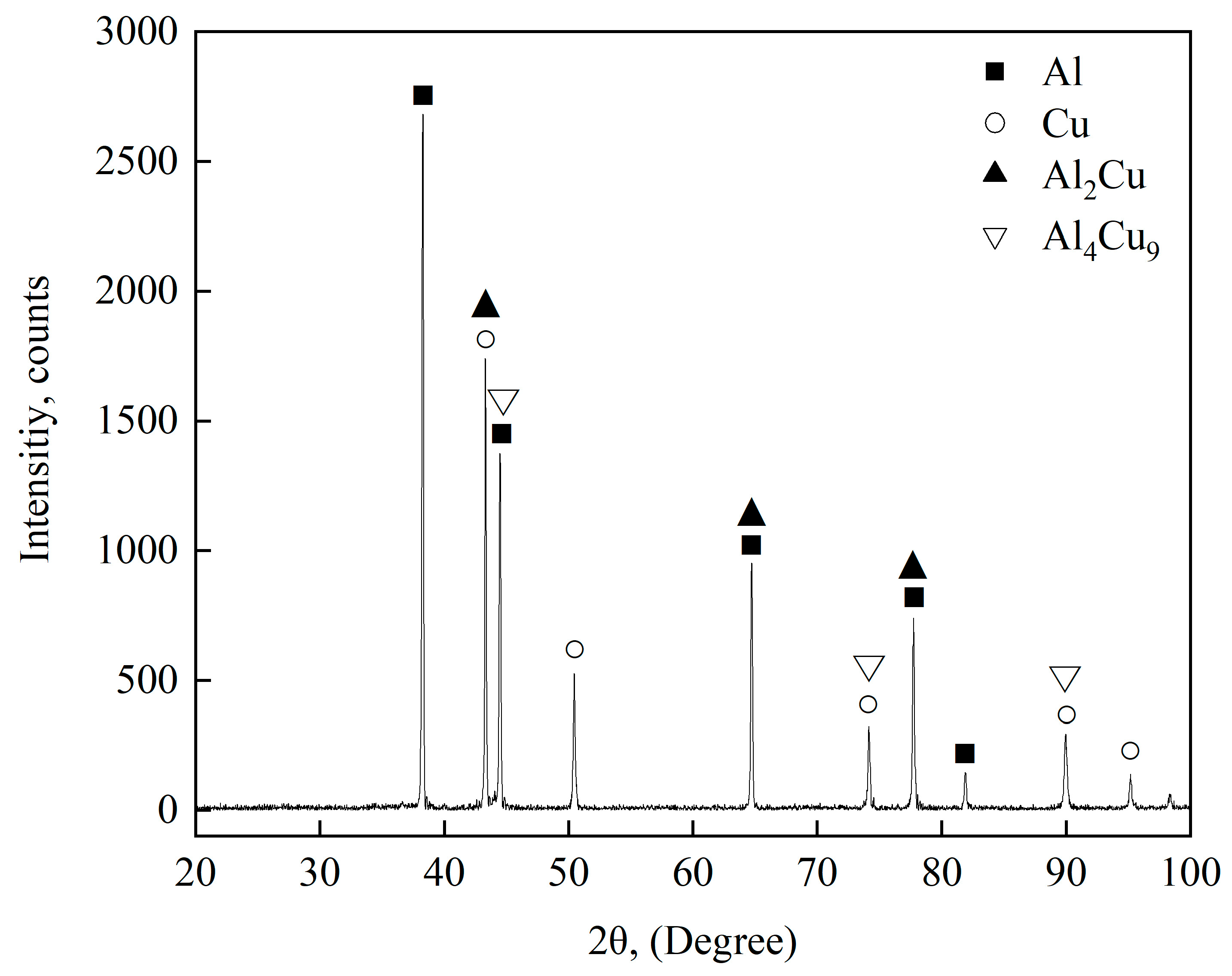
Figure 6.
Transmission Electron Microscope (TEM) micrographs of the copper-rich region: (a) Al2Cu particles, (b) Al4Cu9 particles.
Figure 6.
Transmission Electron Microscope (TEM) micrographs of the copper-rich region: (a) Al2Cu particles, (b) Al4Cu9 particles.
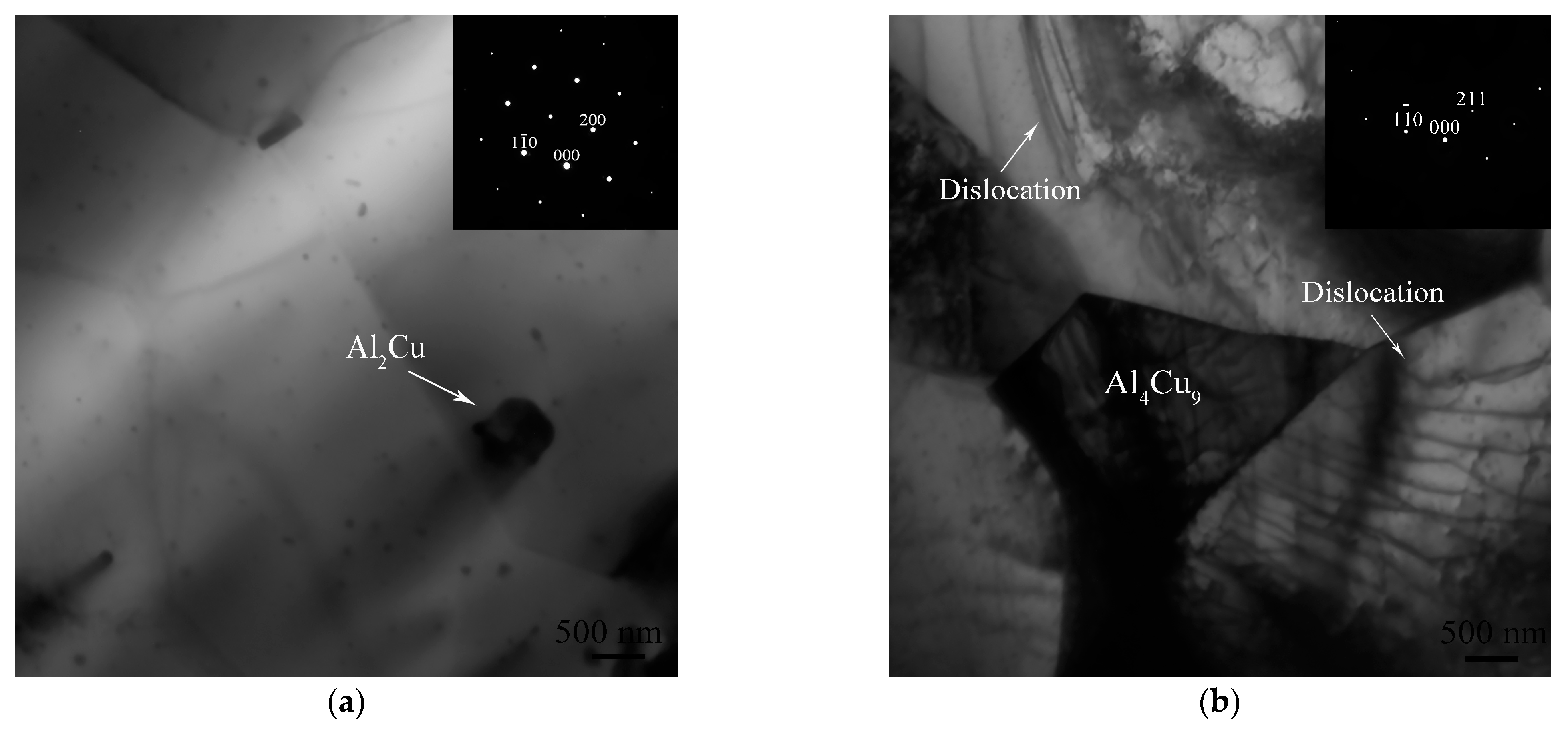
Figure 7.
(a) Energy Dispersive Spectrometer (EDS) test positions at interface; (b) EDS analysis results.
Figure 7.
(a) Energy Dispersive Spectrometer (EDS) test positions at interface; (b) EDS analysis results.
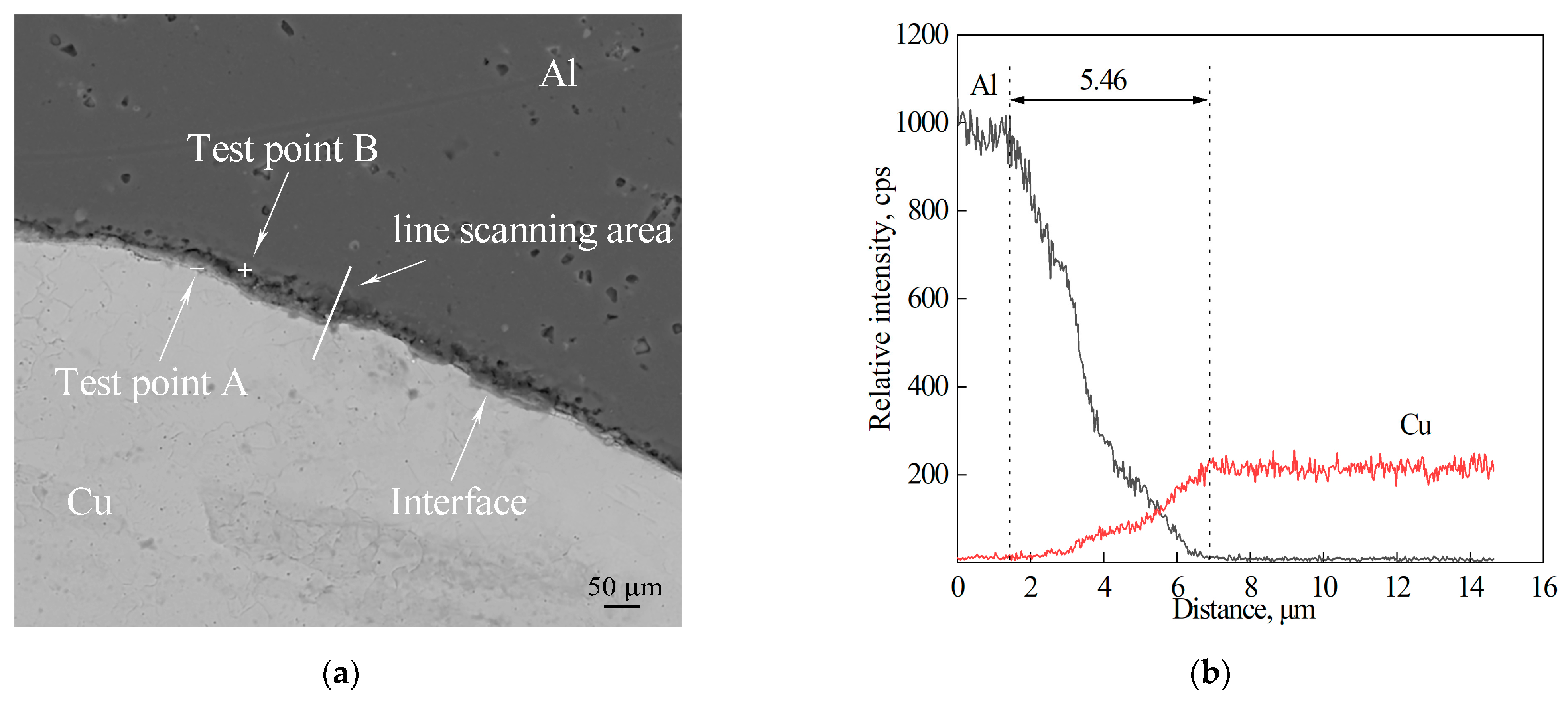
Figure 8.
(a) Microhardness curve parallel to the interface; (b) microhardness curve perpendicular to the interface.
Figure 8.
(a) Microhardness curve parallel to the interface; (b) microhardness curve perpendicular to the interface.
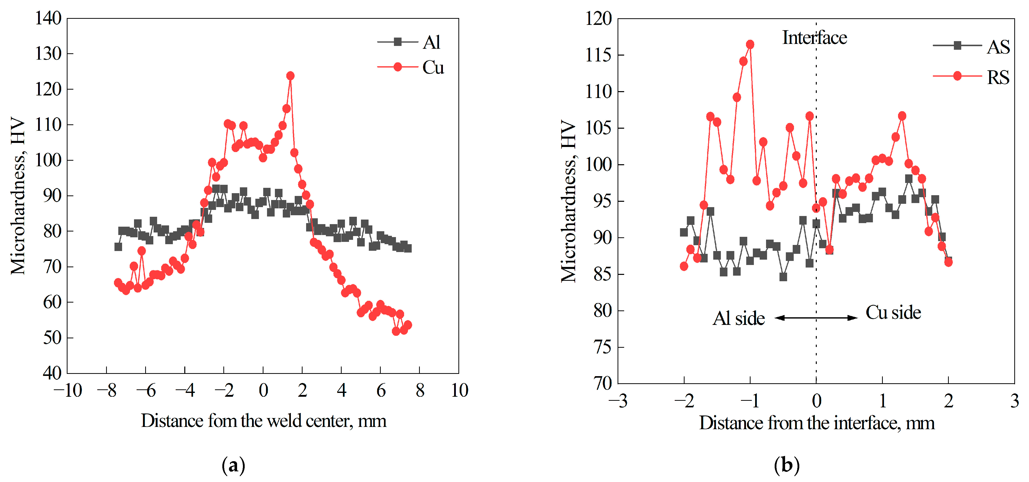
Figure 9.
The stress–strain curve of the Al/Cu lap joint.
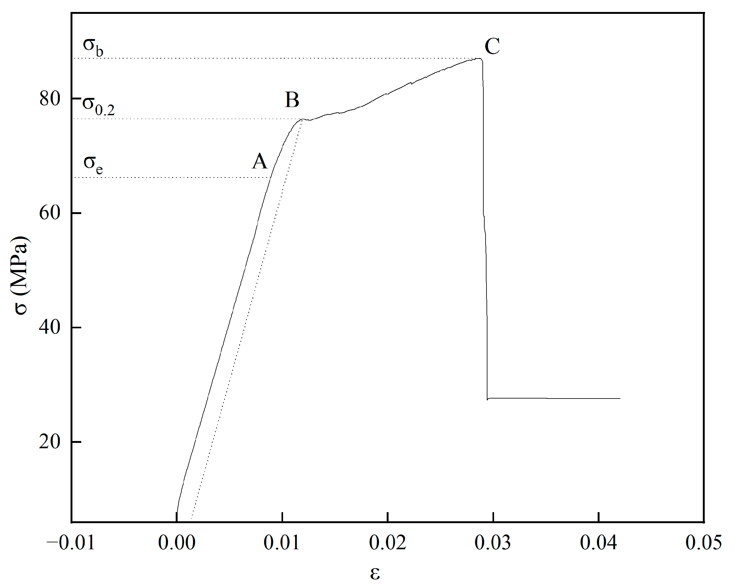
Figure 10.
(a) Fracture position of the lap joint; (b) fracture morphology; (c) river pattern morphology; (d) dimple morphology.
Figure 10.
(a) Fracture position of the lap joint; (b) fracture morphology; (c) river pattern morphology; (d) dimple morphology.


Table 1.
Chemical compositions of base metals (Wt%).
| 5083 Al | T2 Copper | |
|---|---|---|
| Al | 92.23 | - |
| Cu | - | 99.90 |
| Si | 0.40 | - |
| Mg | 4.90 | - |
| Zn | 0.23 | - |
| Mn | 1.0 | - |
| Ti | 0.13 | - |
| Cr | 0.23 | - |
| Fe | 0.40 | - |
Table 2.
Thermophysical parameters of base metals.
| Tensile Strength (MPa) | Elongation (%) | Melting Point (°C) | Thermal Conductivity (W/mK) | |
|---|---|---|---|---|
| T2 copper | 330 | 22 | 1083 | 359 |
| 5083 Al | 270 | 18 | 660 | 117 |
Disclaimer/Publisher’s Note: The statements, opinions and data contained in all publications are solely those of the individual author(s) and contributor(s) and not of MDPI and/or the editor(s). MDPI and/or the editor(s) disclaim responsibility for any injury to people or property resulting from any ideas, methods, instructions or products referred to in the content. |
© 2023 by the authors. Licensee MDPI, Basel, Switzerland. This article is an open access article distributed under the terms and conditions of the Creative Commons Attribution (CC BY) license (https://creativecommons.org/licenses/by/4.0/).
Share and Cite
MDPI and ACS Style
Jiang, F.; Wang, W.; Zhang, X.; Gong, W. Microstructure and Mechanical Properties of Friction Stir Lap Welding Joint of Al/CU Dissimilar Metals. Metals 2023, 13, 1969. https://doi.org/10.3390/met13121969
AMA Style
Jiang F, Wang W, Zhang X, Gong W. Microstructure and Mechanical Properties of Friction Stir Lap Welding Joint of Al/CU Dissimilar Metals. Metals. 2023; 13(12):1969. https://doi.org/10.3390/met13121969
Chicago/Turabian StyleJiang, Fan, Wenquan Wang, Xinge Zhang, and Wenbiao Gong. 2023. "Microstructure and Mechanical Properties of Friction Stir Lap Welding Joint of Al/CU Dissimilar Metals" Metals 13, no. 12: 1969. https://doi.org/10.3390/met13121969
Note that from the first issue of 2016, this journal uses article numbers instead of page numbers. See further details here.