
Achieving High Plasticity and High Toughness of Low-Carbon Low-Alloy Steel through Intercritical Heat Treatment
1
Qingdao Premier Bearing Institute, Qingdao 266400, China
2
School of Mechanical Engineering, Shenyang University of Technology, Shenyang 110870, China
3
State Key Laboratory of Rolling and Automation, Northeastern University, Shenyang 110819, China
*
Author to whom correspondence should be addressed.
Metals 2023, 13(10), 1737; https://doi.org/10.3390/met13101737
Submission received: 3 September 2023
/
Revised: 27 September 2023
/
Accepted: 29 September 2023
/
Published: 13 October 2023
(This article belongs to the Special Issue Metal Rolling and Heat Treatment Processing)
Abstract
:Medium manganese steel has excellent comprehensive properties due to the TRIP effect of retained austenite, but its welding performance is unsatisfactory for its high alloy content. This study obtained retained austenite in low-carbon low-alloy steel with low contents of silicon and manganese elements through intercritical heat treatment. The influence of intercritical quenching temperature on the content and characteristics of the retained austenite, as well as the functional mechanism of the retained austenite during low-temperature impact, was studied. The results showed that the content of the retained austenite increased from 12% to 17%, and its distribution extended from grain boundaries to martensite lath boundaries, with increasing intercritical quenching temperature. The retained austenite on the grain boundaries was in blocks, and that on the martensitic lath boundaries formed slender domains. The stability of the retained austenite was achieved through the enrichment of C and Mn during intercritical heat treatment. The contribution of retained austenite to low-temperature mechanical properties was closely related to its stability. The retained austenite with poor stability underwent martensite transformation at low temperatures, and the high-carbon martensite was a brittle phase that became the nucleation site of cracks or the path of crack growth during impact. Stable retained austenite passivated crack tips and hindered crack propagation during impacts, which improved the impact performance of the steel.
1. Introduction
In recent years, medium manganese steel with Mn contents from 4 to 12 wt.% has attracted widespread attention due to its high strength, plasticity, and toughness [1,2,3,4,5,6]. Retained austenite plays a great role in improving the ductility and toughness of the steel [7,8,9]. The uniform extension and toughness can be improved by the deformation-induced transformation of retained austenite when the steel deforms [10,11,12]. However, due to the high manganese content of medium manganese steel, its welding performance is poor, which limits its widespread use [13,14]. Low-alloy steel has excellent welding performance and is widely used in daily life. Introducing retained austenite that can be stable at room temperature or even low-temperature into low-alloy steel with low-carbon and manganese contents has always been a hot research topic.
Numerous methods have been developed to obtain multiphase structures comprised of austenite and one or two other phases, such as quenching and partitioning (Q&P) [15,16,17,18,19,20,21] and TRIP treatment [22,23,24,25]. These methods are thought to obtain retained austenite by stabilizing austenite through diffusion of carbon from adjacent carbon-rich martensite or bainite to austenite [26]. However, it is very difficult to obtain plenty of retained austenite in low-carbon low-alloy steel. The low content of Si cannot effectively inhibit the precipitation of carbides, resulting in insufficient enrichment of carbon [27]. Recently, an intercritical heat treatment [28,29,30,31,32,33,34] was proposed to obtain retained austenite in high Mn and Ni steel via diffusion of Mn and Ni to austenite to stabilize reverted austenite. Austenite enriched with both C and Mn is sufficiently stable at room temperature, even low temperatures, and the effect of silicon is greatly reduced.
In this study, the authors attempted to increase only the content of Mn appropriately on the basis of the composition of traditional low-carbon low-alloy steel and aimed to introduce retained austenite into conventional low-carbon low-alloy steel through intercritical heat treatment to improve its overall properties without reducing welding performance. The influence of the intercritical quenching temperature on the content, size, distribution, and morphology of retained austenite was studied, and the mechanism of stabilization of retained austenite was analyzed. The functional mechanism of retained austenite during low-temperature impact was explored.
2. Materials and Experimental Procedure
The materials used in this study were smelted in a vacuum induction melting furnace (VIM200L-00); the chemical composition was 0.12C-2.98Mn-0.21Si (in wt.%) and Fe (the balanced). The addition of elements was carefully considered based on production experience and calculations, such as less carbon for better matching of strength and toughness, an appropriate level of Mn for control of retained austenite and good welding performance, and less Si for ensuring the surface quality of medium-thick plates. First, the ingot was forged into 100 × 100 × 100 square billets for rolling using a forging machine (C41-750B). After holding at 1200 °C for 3 h, the experimental steel was rolled into 12 mm thick steel plates using a two-stage controlled rolling process on a Ø450 × 450 two-high reversing hot mill. Intercritical heat treatments were conducted on hot-rolled steel plates to achieve the best combination of strength, toughness, and plasticity. A schematic diagram of the controlled rolling and intercritical heat treatment process is shown in Figure 1. After hot rolling, the experimental steel was austenitized, then quenched to obtain a uniform structure, followed by intercritical quenching at 700, 720 and 740 °C (IQ700, IQ720 and IQ740, respectively), and finally critical quenched at 680 °C. The effects of intercritical quenching temperature on the structure and properties were studied.
Metallographic samples were cut from intercritical heat treatment plates with different intercritical quenching temperatures to analyze their microstructure and the characteristics of retained austenite. A Zeiss Ultra-55 (Zeiss Microscopy, Munich, Germany) scanning electron microscope operating at 15 KV was used to perform scanning electron microscopy (SEM) to observe the microstructure of steels under different intercritical quenching temperatures, and electron backscattering diffraction (EBSD) was used to investigate features such as the shape, size and distribution of retained austenite. The detailed characteristics of retained austenite were studied using FEI Tecnai G2 F20 (Thermo Fisher Scientific, Waltham, MA, American) transmission electron metallography (TEM). The distribution and variation of elements were obtained by energy-dispersive X-ray spectroscopy (EDS) using a JEOL JXA-8530F (JEOL, Tokyo, Japan) field emission electron probe (EPMA). The retained austenite was detected in the experiment steels using an X-ray diffraction (XRD) equipped with a Cu target. The tensile testing was performed using the standard style of 5 mm diameter and 25 mm gauge length and was conducted on a universal tensile testing machine at room temperature. Specimens for impact tests were cut along the longitudinal direction of the plates, and low-temperature toughness performance testing was conducted on an Instron 9250HV (Instron, Norwood, MA, USA) falling impact testing machine using standard 10 mm × 10 mm × 55 mm V-notched samples. The force-displacement curves can be automatically recorded by a computer.
3. Results and Discussion
3.1. Microstructure Characterization
The microstructure of steels after austenitization and intercritical heat treatment at different intercritical quenching temperatures is shown in Figure 2. The microstructure of the experimental steel after hot rolling and austenitization quenching was uniform lath martensite (Figure 2a). This indicated that the defects formed during the casting and solidification process in the experimental steel healed after hot rolling, which was a prerequisite for obtaining good overall properties of the experimental steel after subsequent heat treatment. There were significant differences in the microstructure of the experimental steels after the same critical quenching and different intercritical quenching procedures, as shown in Figure 2b–d. The microstructure of IQ700 was mainly tempered martensite, and there was little fresh martensite. The fresh martensite of IQ720 obviously increased, but there was still a large amount of tempered martensite. The microstructure of IQ740 was mainly fresh martensite, and there was only a small number of small domains of tempered martensite. Intercritical quenching was incomplete austenitizing quenching; only part of the structure was austenitized and then quenched as fresh martensite, but the structure without austenitizing was only tempered. During the tempering process of martensite, carbon and manganese were discharged into the surroundings, and the austenitized structure absorbed carbon and manganese. More carbon and manganese accumulated in the fresh martensite, which provided good conditions for the formation of retained austenite during critical quenching.
The content of retained austenite in experimental steels under different intercritical quenching temperatures was statistically analyzed using XRD data, as shown in Figure 3. The diffraction pattern (Figure 3a) for the experimental steels had five broad peaks, corresponding to (111)FCC, (110)BCC, (200)FCC, (200)BCC and (211)BCC, respectively. The height of diffraction peaks of FCC in the experimental steels increased with increasing intercritical quenching temperatures, indicating that the content of retained austenite gradually increased. Figure 3b shows that the content of retained austenite increased from 12% for IQ700 to 17% for IQ740. The XRD results indicated that increasing the intercritical quenching temperature enhanced the effect of element segregation, allowing more reversed austenite to be retained at room temperature after critical quenching. However, the role of retained austenite in steel depended not only on its content but also on its size, morphology, distribution, and stability. XRD provided only a macroscopic measurement of the content of retained austenite in steel, and it could not fully display the characteristics of retained austenite. Therefore, further detailed characterization of retained austenite was needed.
EBSD characterization was performed to investigate the effect of intercritical quenching temperature on the microstructure of the experimental steels. Results of the EBSD analysis of experimental steels intercritical quenched at 700, 720 and 740 °C are shown in Figure 4, Figure 5 and Figure 6. The BC maps show the microstructure morphologies within the corresponding selected areas of different steels; phase maps indicate the distribution of retained austenite, and IPF maps show different colors that represent different crystal orientations of each point. The red areas in the phase maps represent the distribution of retained austenite in the microstructure, as shown in Figure 4b, Figure 5b and Figure 6b. The quantity, size, and distribution of retained austenite are closely related to the intercritical quenching temperature. The amount of retained austenite increased with the increase in intercritical quenching temperature. The areas of retained austenite first increased and then decreased, mainly because the distribution of retained austenite changed. The combination of phase maps, IPF maps and grain boundary maps determined that the retained austenite in IQ700 and IQ720 was mainly distributed on the grain boundaries, while the retained austenite in IQ740 was not only limited to the grain boundaries but was also distributed on the martensitic lath boundaries. The increase in the number of nucleation points led to the smaller areas of retained austenite. This may have been because element enrichment occurred not only at the grain boundaries but also at the martensite lath boundaries. When the intercritical quenching temperature increased to 740 °C, the number of nucleation points of reversed austenite greatly increased. Alternatively, the reverted austenite at the martensitic boundaries may have been stable at room temperature until the intercritical quenching temperature reaches 740 °C.
EBSD provided a more detailed representation of the distribution, size, and quantity of retained austenite in experimental steel, while TEM accurately represented the morphology of retained austenite. Figure 7 shows the morphology of retained austenite in IQ720. Compared with the bright field map (Figure 7a) and the dark field map (Figure 7b), retained austenite appeared black in the bright field image. The diffraction pattern of retained austenite is shown in Figure 7c. This was because the retained austenite was relatively soft and prone to concentrate under stress. The retained austenite in IQ720 mainly appeared in the shape of a block, which was consistent with the EBSD observations. In addition, Figure 7e shows the diffraction pattern of the microstructure in the circled area in Figure 7d, which was <113> twin martensite. This was because the C element accumulated in the reversed austenite during the intercritical heat treatment process, and the content of the C element in the reversed austenite reached a very high level during quenching. Reversed austenite with high C content could be stable at room temperature without martensite transformation, but there was still some reversed austenite that could not reach the C content to reduce its Ms point below room temperature, and martensite transformation occurred again during quenching. In the quenching process of C-rich austenite, the strain energy increased because the transformation point of martensite decreased, and a fine twin substructure formed during the formation and growth of martensite to adjust the strain energy, causing twin martensite to form. This proved that the segregation of C and Mn occurred during the intercritical quenching process. Figure 8 presents the morphologies of retained austenite in IQ740. This indicated that there were two forms of retained austenite, block retained austenite (Figure 8a,b), similar to IQ720, and slender domains of retained austenite (Figure 8c,d). Reviewing the distribution of retained austenite, Figure 6b clearly shows that the slender areas of retained austenite corresponded to retained austenite between the martensitic laths, while the large blocky areas of retained austenite corresponded to retained austenite between the grain boundaries.
The intercritical heat treatment process could introduce stable retained austenite at room temperature into low-carbon low-alloy steel, which was inevitably accompanied by the migration, diffusion, and aggregation of C and Mn. EMPA was used to conduct surface and line scanning on the experimental steels to analyze the variations in C and Mn during intercritical heat treatment. Figure 9 shows the distribution of C and Mn elements in the microstructure of IQ700. The distributions of C and Mn in the microstructure were uneven, and there was obvious aggregation at the grain boundaries and martensite lath boundaries. Figure 9a,b showed that the aggregation of Mn and C remained basically synchronized, and C and Mn atoms simultaneously aggregated in a certain region. The line scanning results are shown in Figure 9c. The red curve represents the distribution of C on the green line, while the blue curve indicates the distribution of Mn along the green line. The peak positions of the two curves corresponded. This indicated that there was a simultaneous aggregation of C and Mn on the green line. The chemical composition of retained austenite was analyzed using TEM, as shown in Figure 9d. The black microstructure was retained austenite. EDS diffraction analysis was conducted on it and the surrounding white area, and the contents of C and Mn in the retained austenite were as high as 2.74% and 5.07%, respectively. The content of C in the white area was close to 0%, and the percentage of Mn element was 1.05%. The above results indicated that there was a significant enrichment of C and Mn elements in retained austenite. Mn had the effect of expanding the austenite zone, and the stability of austenite was directly proportional to its C and Mn contents [35]. The combined effects of the two factors caused the Ms point of retained austenite to decrease below room temperature so that it can be stably retained at room temperature without transformation.
3.2. Mechanical Properties
Figure 10 shows the effect of the intercritical quenching temperature on the mechanical properties of the experimental steel. The intercritical quenching temperature had little effect on the tensile properties of the experimental steel but a significant impact on its low-temperature impact performance. IQ720 had less tensile strength but more elongation and good strength–ductility balance (TS × EL). The tensile properties of IQ700 and IQ740 were similar. As the intercritical quenching temperature increased, the −40 °C impact energy of the experimental steel increased from 100 J to 110 J and then decreased to 43 J. IQ740 had the highest retained austenite content but its low-temperature impact toughness was the worst. This indicated that the characteristics of retained austenite significantly influenced impact toughness.
To reveal the reasons for abnormal low-temperature impact performance, the force-displacement curves of the impact processes were analyzed, as shown in Figure 11. The three curves started to rise linearly, and when the force reached 10,000 N, the rising rate of the curves gradually slowed down. When the force reached Fgy, the samples yielded, and the deformation mode changed from elastic deformation to plastic deformation. The yield points of the experimental steels with different intercritical quenching temperatures were the same. When the curve reached its highest point Fm, cracks began to nucleate, followed by stable crack propagation until unstable crack propagation began. The value of the force at the beginning of the sharp decrease (Fiu) indicated the beginning of unstable crack propagation. The force at the end of the sharp decrease (Fa) indicated the termination of unstable crack propagation. Stable crack propagation is a ductile fracture, while unstable crack propagation is a brittle fracture. Stable crack propagation absorbed more energy in the force-displacement curves of IQ700 and IQ720 but less energy for IQ740. Crack formation absorbed less energy in IQ700 than in IQ720, and the absorption energy for the formation of the shear lip was the same. The energy absorbed for crack formation and shear lip formation in IQ740 was small, which indicated that the retained austenite underwent martensite transformation when cooled to −40 °C. When intercritical quenching treatment was performed at a higher temperature, the volume fraction of martensite without austenitization was smaller. During the subsequent critical quenching process, less C and Mn accumulated in the austenite, and the stability of the retained austenite was relatively poor. Therefore, more retained austenite in IQ740 transformed into martensite at low-temperature, resulting in poor impact toughness. The areas enclosed by the force-displacement curves and the X-axis were the impact energies. The impact energy was clearly largest for IQ720 and smallest for IQ740.
Corresponding to the impact force-displacement curves, the impact fracture surfaces can also reveal the fracture process of the specimens. Figure 12 shows the macroscopic and microscopic morphologies of the impact fracture surfaces of the experimental steels quenched at different intercritical temperatures. The macroscopic morphology of the impact fracture surface was divided into three regions, namely, the fibrous region, the radiation region, and the shear lip, as shown in Figure 12a–c. The fibrous region and shear lip of IQ740 were relatively small, and the radiation region was the largest. The fibrous region and shear lip of IQ720 were the largest, the radiation region was the smallest, and there were two fibrous regions. The fibrous regions corresponded to the stable crack propagation stage in the force-displacement curves between Fm and Fiu. The stable propagation stage of the IQ720 crack was the longest, and it corresponded to the largest fibrous region. The radiation region represented the unstable propagation of cracks after reaching the critical size. IQ740 was the first to undergo unstable crack propagation, with the largest radiation region. The stage after the sharp decrease in the force-displacement curve corresponded to the shear lip. The shear lips in IQ720 and IQ700 were the same size, and the final stages of the force-displacement curves were also the same. Therefore, the force-displacement curves corresponded completely to the fracture morphologies. The microscopic morphologies of the impact fracture radiation regions are shown in Figure 12(a1–c1). The direction of crack propagation in the radiation region of IQ720 underwent multiple changes, and there were few secondary cracks. IQ740 had many secondary cracks with larger sizes, indicating poor toughness.
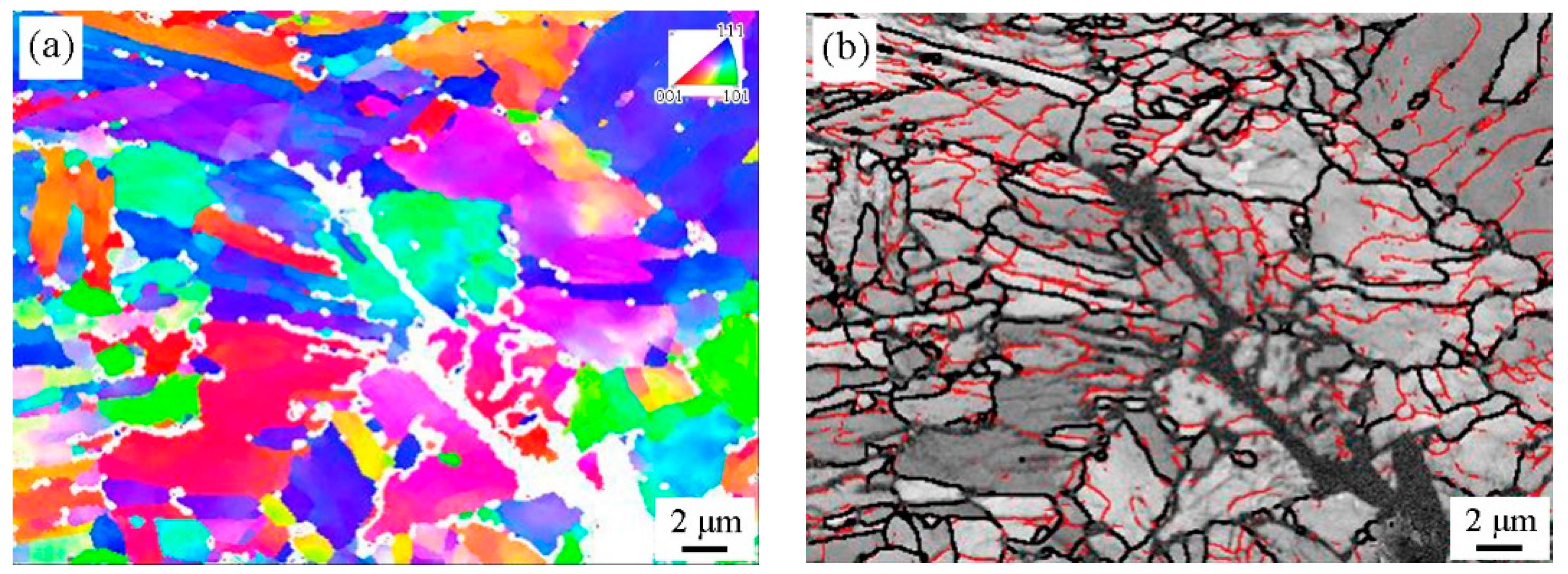
To further analyze the reason for the poor toughness of IQ740 with the most retained austenite, EBSD was used to characterize the secondary crack on the impact fracture surface, as shown in Figure 13. Figure 13b indicated that retained austenite was not present near the IQ740 fracture surface. Combined with the IPF map (Figure 13a), this showed that the secondary crack propagated through the grain along martensitic lath boundaries. The crack deflected at the grain boundaries in the process of propagation, and finally, the crack propagation stopped at the triangular grain boundary. This indicated that the energy required for the crack to propagate along the martensitic lath boundaries was small. There were many domains of retained austenite distributed on the martensitic lath boundaries of IQ740, but the crack still propagated along the martensitic lath boundary. This may have been because the retained austenite transformed into high carbon martensite at low-temperature. The high carbon martensite was a brittle phase, and it became the crack propagation path, causing poor low-temperature toughness [36].
4. Conclusions
In this study, retained austenite was formed in low-carbon low-alloy steel by appropriately adding manganese and applying intercritical heat treatment, which achieved good overall properties. Interestingly, we found that the low-temperature toughness of experimental steel is not simply determined by the content of retained austenite. The effect of retained austenite is closely related to its stability. The main conclusions were as follows:
- (1)
- The intercritical quenching temperature had a significant impact on the content, domain size, morphology, and distribution of retained austenite. With increasing intercritical quenching temperature, the content of retained austenite increased, the domain size increased first and then decreased, the distribution extended from the grain boundary to the martensite lath boundary, and the morphology developed from blocks to strips;
- (2)
- During the critical heat treatment process, significant element aggregation occurred, and a large amount of C and Mn from the surrounding structure accumulated in the retained austenite, which made it stable at room temperature and even low temperatures;
- (3)
- The characteristics of retained austenite had a small effect on the tensile properties, but they had a significant impact on low-temperature impact properties. The impact energy of IQ720 at −40 °C reached 110 J, while the impact energy of IQ740 with the highest retained austenite content was only 40 J, which was closely related to the stability of the retained austenite;
- (4)
- The crack formation absorption energy of IQ740 was relatively small, and the corresponding fiber region of the impact fracture was small. This indirectly indicated that retained austenite transformed into brittle high-carbon martensite, which did not hinder crack growth but became the nucleation site of the crack. The retained austenite in IQ720 was stable at low temperatures, which hindered crack propagation and improved the impact performance of the steel;
- (5)
- The use of medium manganese steel is greatly limited by its welding performance. Subsequent research may mainly focus on improving the welding performance of medium manganese steel to meet the needs of industrial applications. Appropriately reducing the manganese content may be a good solution.
Author Contributions
Methodology, J.L., X.D. and Z.W.; Validation, J.L., Resources, J.L., X.D. and Z.W.; Data curation, L.H.; Writing—original draft, L.H.; Writing—review & editing, L.H. All authors have read and agreed to the published version of the manuscript.
Funding
The authors acknowledge support from the National Natural Science Foundation of China (No. U1960112, 52101165).
Data Availability Statement
Not applicable.
Conflicts of Interest
The authors declare no conflict of interest.
References
- Suh, D.W.; Kim, S.J. Medium Mn transformation-induced plasticity steels: Recent progress and challenges. Scri. Mater. 2017, 126, 63–67. [Google Scholar] [CrossRef]
- Field, D.M.; Magagnosc, D.J.; Hornbuckle, B.C.; Lloyd, J.T.; Limmer, K.R. Tailoring γ-austenite stability to improve strength and toughness of a medium-Mn steel. Metall. Mater. Trans. A 2022, 53, 2530–2543. [Google Scholar] [CrossRef]
- Kwok, T.W.J.; Gong, P.; Xu, X.; Nutter, J.; Rainforth, W.M.; Dye, D. Microstructure evolution and tensile behaviour of a cold rolled 8wt pct Mn medium manganese steel. Metall. Mater. Trans. A 2021, 53, 597–609. [Google Scholar] [CrossRef]
- Yang, D.P.; Du, P.J.; Wu, D.; Yi, H.L. The microstructure evolution and tensile properties of medium-Mn steel heat-treated by a two-step annealing process. J. Mater. Sci. Technol. 2021, 75, 205–215. [Google Scholar] [CrossRef]
- Li, Z.C.; Ding, H.; Misra, R.D.K.; Cai, Z.H. Microstructure-mechanical property relationship and austenite stability in medium-Mn TRIP steels: The effect of austenite-reverted transformation and quenching-tempering treatments. Mater. Sci. Eng. A 2017, 682, 211–219. [Google Scholar] [CrossRef]
- Kwiatkowski da Silva, A.; Inden, G.; Kumar, A.; Ponge, D.; Gault, B.; Raabe, D. Competition between formation of carbides and reversed austenite during tempering of a medium-manganese steel studied by thermodynamic-kinetic simulations and atom probe tomography. Acta Mater. 2018, 147, 165–175. [Google Scholar]
- Yoon, Y.C.; Lee, S.I.; Oh, D.K.; Hwang, B. Microstructure and low-temperature toughness of intercritically annealed Fe–9Mn-0.2C Medium-Mn steels containing Al, Cu, and Ni. Mater. Sci. Eng. A 2022, 854, 143804. [Google Scholar] [CrossRef]
- Wu, R.M.; Xu, Y.; Li, K.C. Role of metastable austenite on crack resistance of quenching and partitioning sheet steels. Metals 2023, 13, 762. [Google Scholar] [CrossRef]
- Shin, S.H.; Yoon, Y.C.; Lee, S.I.; Hwang, B. Improvement in low-temperature toughness of Fe-6.5Mn-0.08C Medium-Mn steel by multi-step heat treatment. J. Mater. Res. Technol. 2023, 26, 3558–3570. [Google Scholar] [CrossRef]
- Jing, S.Y.; Ding, H.; Ren, Y.P.; Cai, Z.H. A new insight into annealing parameters in tailoring the mechanical properties of a medium Mn steel. Scripta Mater. 2021, 202, 114019. [Google Scholar] [CrossRef]
- Wan, X.H.; Liu, G.; Yang, Z.G.; Chen, H. Flash annealing yields a strong and ductile medium Mn steel with heterogeneous microstructure. Scripta Mater. 2021, 198, 113819. [Google Scholar] [CrossRef]
- Kim, D.H.; Kang, J.H.; Ryu, J.H.; Kim, S.J. Effect of austenitization of cold-rolled 10 wt% Mn steel on microstructure and discontinuous yielding. Mater. Sci. Eng. A 2020, 774, 138930. [Google Scholar] [CrossRef]
- Stadler, M.; Schnitzer, R.; Gruber, M.; Steineder, K.; Hofer, C. Microstructure and Local Mechanical Properties of the Heat-Affected Zone of a Resistance Spot Welded Medium-Mn Steel. Materials 2021, 14, 3362. [Google Scholar] [CrossRef] [PubMed]
- Pouranvari, M.; Marashi, S.P.H. Critical review of automotive steels spot welding: Process, structure and properties. Sci. Technol. Weld. Joi. 2013, 18, 361–403. [Google Scholar] [CrossRef]
- Speer, J.; Matlock, D.K.; De Cooman, B.C.; Schroth, J.G. Carbon partitioning into austenite after martensite transformation. Acta Mater. 2003, 51, 2611–2622. [Google Scholar] [CrossRef]
- Clarke, A.J.; Speer, J.G.; Miller, M.K.; Hackenberg, R.E.; Edmonds, D.V.; Matlock, D.K.; Rizzo, F.C.; Clarke, K.D.; De Moor, E. Carbon partitioning to austenite from martensite or bainite during the quench and partition (Q&P) process: A critical assessment. Acta Mater. 2008, 56, 16–22. [Google Scholar]
- Wu, R. Effect of Retained Austenite on the Fracture Toughness of Quenching and Partitioning (Q&P)-Treated Sheet Steels. Metall. Mater. Trans. A 2014, 45, 1892–1902. [Google Scholar]
- Jin, X.; Totten, G.E.; Colas, R. Encyclopedia of Iron, Steel, and Their Alloys; CRC Press: Boca Raton, FL, USA, 2016; pp. 2761–2775. [Google Scholar]
- Wang, F.; Zhu, Y.; Zhou, H.; Jiang, B.; Wang, G. A novel microstructural design and heat treatment technique based on gradient control of carbon partitioning between austenite and martensite for high strength steels. Sci. China Technol. Sci. 2013, 56, 1847–1857. [Google Scholar] [CrossRef]
- Zhong, N.; Wang, X.D.; Wang, L.; Rong, Y.H. Enhancement of the mechanical properties of a Nb-microalloyed advanced high-strength steel treated by quenching–partitioning–tempering process. Mater. Sci. Eng. A 2009, 506, 111–116. [Google Scholar] [CrossRef]
- Yi, H.L.; Chen, P.; Hou, Z.Y.; Hong, N.; Cai, H.L.; Xu, Y.B.; Wu, D.; Wang, G.D. A novel design: Partitioning achieved by quenching and tempering (Q–T & P) in an aluminium-added low-density steel. Scripta Mater. 2013, 68, 370–374. [Google Scholar]
- Kuziak, R.; Kawalla, R.; Waengler, S. Advanced high strength steels for automotive industry. Arch. Civ. Mech. Eng. 2008, 8, 103–117. [Google Scholar] [CrossRef]
- Luo, H.W.; Dong, H. New ultrahigh-strength Mn-alloyed TRIP steels with improved formability manufactured by intercritical annealing. Mater. Sci. Eng. A 2015, 626, 207–212. [Google Scholar] [CrossRef]
- Grassel, O.; Krüger, L.; Frommeyer, G.; Meyer, L.W. High strength Fe–Mn–(Al, Si) TRIP/TWIP steels development—Properties—Application. Int. J. Plast. 2000, 16, 1391–1409. [Google Scholar] [CrossRef]
- De Cooman, B.C. Structure–properties relationship in TRIP steels containing carbide-free bainite. Curr. Opin. Solid State Mater. Sci. 2004, 8, 285–303. [Google Scholar] [CrossRef]
- Dai, Z.B.; Chen, H.; Ding, R.; Lu, Q.; Zhang, C.; Yang, Z.G.; van der Zwaag, S. Fundamentals and application of solid-state phase transformations for advanced high strength steels containing metastable retained austenite. Mater. Sci. Eng. R 2021, 143, 100590. [Google Scholar] [CrossRef]
- Sun, B.H.; Fazeli, F.; Scott, C.; Brodusch, N.; Gauvin, R.; Yue, S. The influence of silicon additions on the deformation behavior of austenite-ferrite duplex medium manganese steels. Acta Mater. 2018, 148, 249–262. [Google Scholar] [CrossRef]
- Hu, B.; Luo, H.W. A novel two-step intercritical annealing process to improve mechanical properties of medium Mn steel. Acta Mater. 2019, 176, 250–263. [Google Scholar] [CrossRef]
- Xie, Z.J.; Ren, Y.Q.; Zhou, W.H.; Yang, J.R.; Shang, C.J.; Misra, R.D.K. Stability of retained austenite in multi-phase microstructure during austempering and its effect on the ductility of a low carbon steel. Mater. Sci. Eng. A 2014, 603, 69–75. [Google Scholar] [CrossRef]
- Han, J.; Kang, S.H.; Lee, S.J.; Lee, Y.K. Fabrication of bimodal-grained Al-free medium Mn steel by double intercritical annealing and its tensile properties. J. Alloys Compd. 2016, 681, 580–588. [Google Scholar] [CrossRef]
- Zhou, W.H.; Challa, V.S.A.; Guo, H.; Shang, C.J.; Misra, R.D.K. Structure-mechanical property relationship in a low carbon Nb-Cu microalloyed steel processed through a three-step heat treatment: The effect of tempering process. Mater. Sci. Eng. A 2015, 620, 454–462. [Google Scholar] [CrossRef]
- Arlazarov, A.; Gouné, M.; Bouaziz, O.; Hazotte, A.; Petitgand, G.; Barges, P. Evolution of microstructure and mechanical properties of medium Mn steels during double annealing. Mater. Sci. Eng. A 2012, 152, 31–39. [Google Scholar] [CrossRef]
- Xu, Y.B.; Hu, Z.P.; Zou, Y.; Tan, X.D.; Han, D.T.; Chen, S.Q.; Ma, D.G.; Misra, R.D.K. Effect of two-step intercritical annealing on microstructure and mechanical properties of hot-rolled medium manganese TRIP steel containing δ-ferrite. Mater. Sci. Eng. A 2017, 688, 40–55. [Google Scholar] [CrossRef]
- Zou, Y.; Xu, Y.B.; Hu, Z.P.; Gu, X.L.; Peng, F.; Tan, X.D.; Chen, S.Q.; Han, D.T.; Misra, R.D.K.; Wang, G.D. Austenite stability and its effect on the toughness of a high strength ultra-low carbon medium manganese steel plate. Mater. Sci. Eng. A 2016, 675, 153–163. [Google Scholar] [CrossRef]
- Hu, B.J.; Zheng, Q.Y.; Lu, Y.; Jia, C.N.; Liang, T.; Zheng, C.W.; Li, D.Z. Stabilizing austenite via intercritical Mn partitioning in a medium Mn steel. Scripta Mater. 2023, 225, 115162. [Google Scholar] [CrossRef]
- Zhou, S.B.; Hu, F.; Zhou, W.; Cheng, L.; Hu, C.Y.; Wu, K.M. Effect of retained austenite on impact toughness and fracture behavior of medium carbon submicron-structured bainitic steel. J. Mater. Res. Technol. 2021, 14, 1021–1034. [Google Scholar] [CrossRef]
Figure 1.
Schematic diagram of the controlled rolling and heat treatment process.
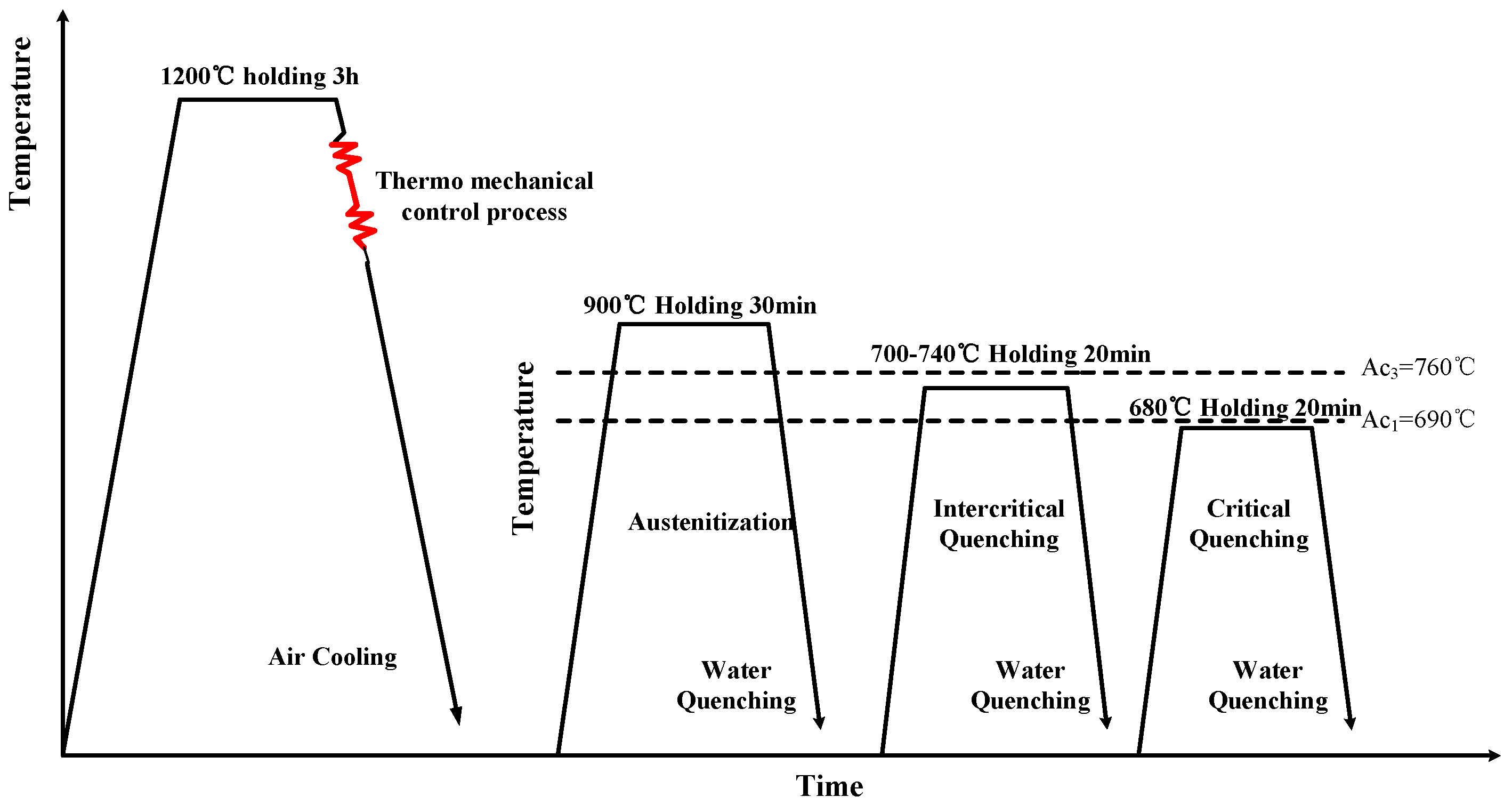
Figure 2.
SEM images of experimental steel after different stages of heat treatments. (a) steel after austenitization; (b) IQ700; (c) IQ720; (d) IQ740.
Figure 2.
SEM images of experimental steel after different stages of heat treatments. (a) steel after austenitization; (b) IQ700; (c) IQ720; (d) IQ740.
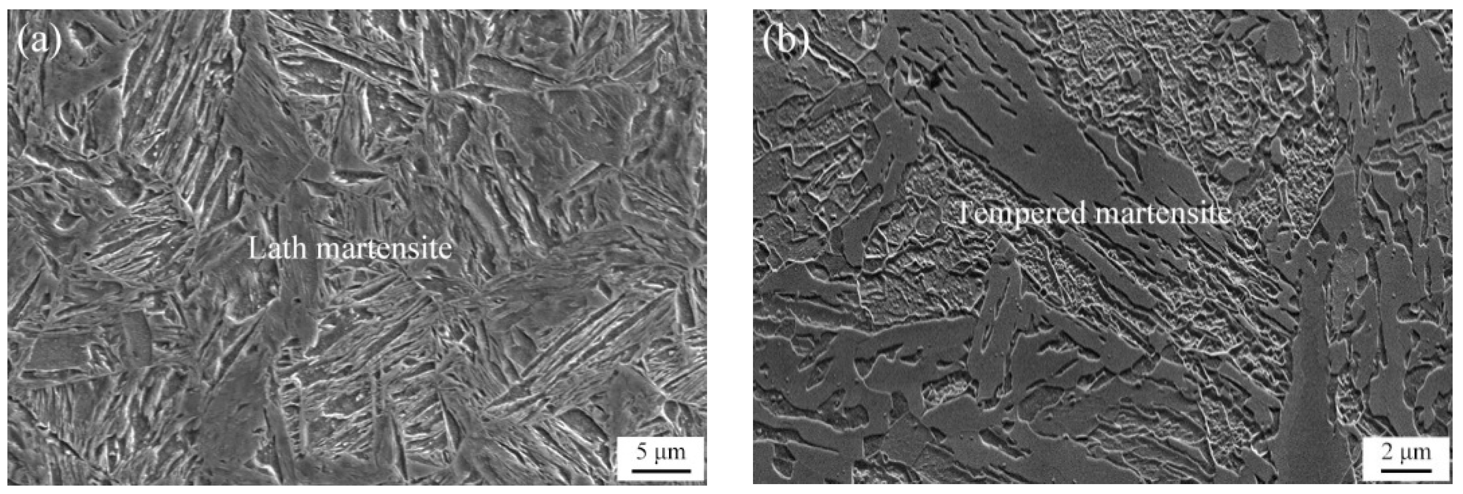

Figure 3.
The diffraction patterns (a) for retained austenite content (b) in experimental steels with different intercritical quenching temperatures.
Figure 3.
The diffraction patterns (a) for retained austenite content (b) in experimental steels with different intercritical quenching temperatures.
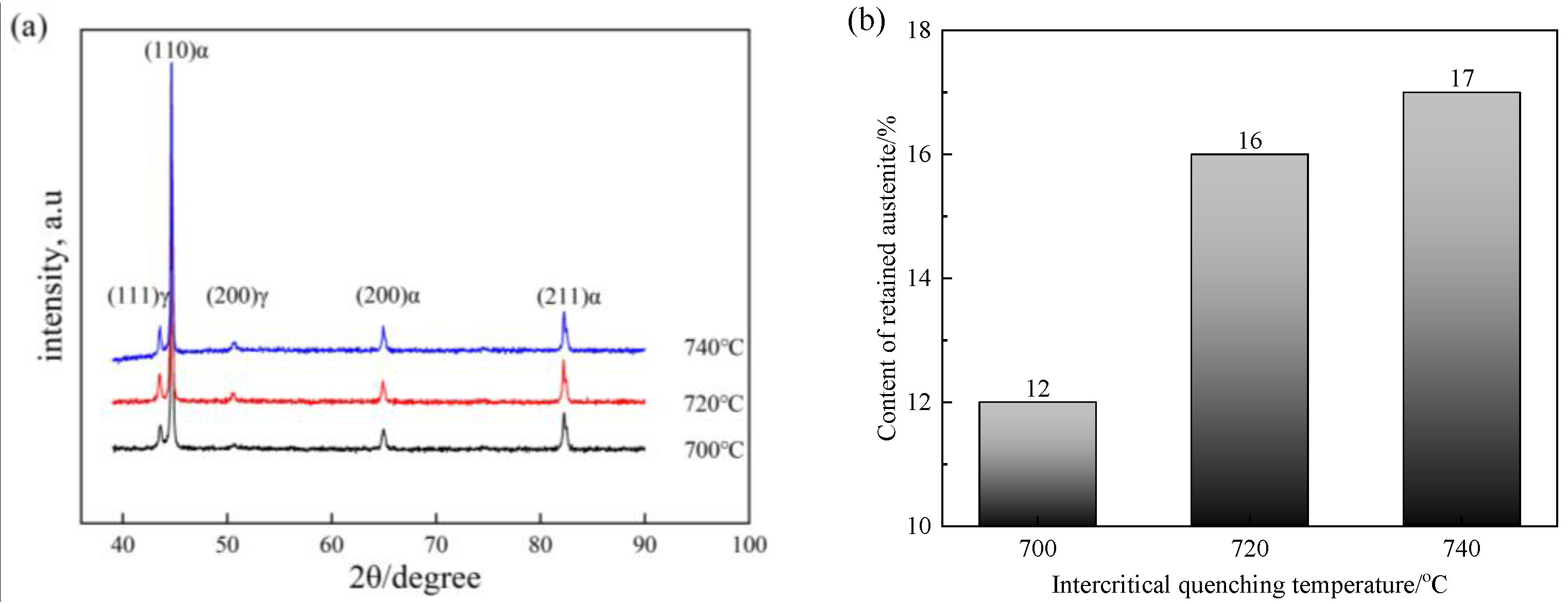
Figure 4.
EBSD analysis of a specimen intercritical quenched at 700 °C. (a) Band Contrast (BC) map of randomly selected areas (b) phase map of retained austenite (c) inverse pole figure (d) map of grain boundaries at different angles.
Figure 4.
EBSD analysis of a specimen intercritical quenched at 700 °C. (a) Band Contrast (BC) map of randomly selected areas (b) phase map of retained austenite (c) inverse pole figure (d) map of grain boundaries at different angles.

Figure 5.
EBSD analysis of a specimen intercritical quenched at 720 °C. (a) Band Contrast (BC) map of randomly selected areas (b) phase map of retained austenite (c) inverse pole figure (d) map of grain boundaries at different angles.
Figure 5.
EBSD analysis of a specimen intercritical quenched at 720 °C. (a) Band Contrast (BC) map of randomly selected areas (b) phase map of retained austenite (c) inverse pole figure (d) map of grain boundaries at different angles.

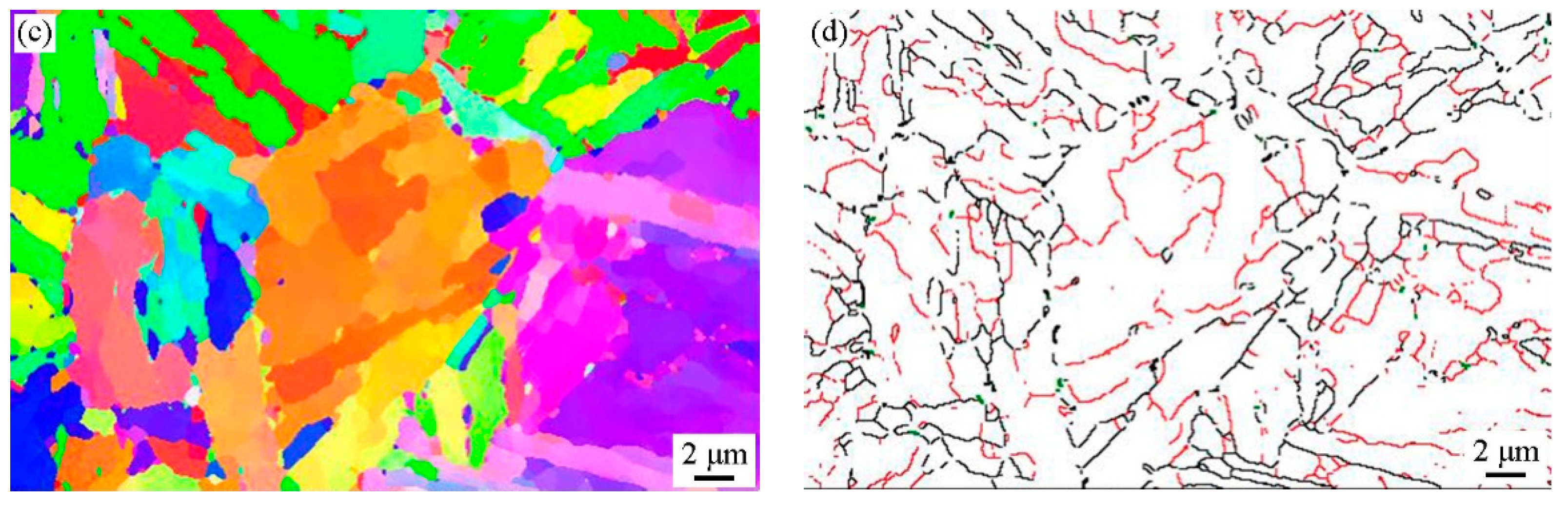
Figure 6.
EBSD analysis of a specimen intercritical quenched at 740 °C. (a) Band Contrast (BC) map of randomly selected areas, (b) phase map of retained austenite, (c) inverse pole figure (IPF), and (d) map of grain boundaries at different angles.
Figure 6.
EBSD analysis of a specimen intercritical quenched at 740 °C. (a) Band Contrast (BC) map of randomly selected areas, (b) phase map of retained austenite, (c) inverse pole figure (IPF), and (d) map of grain boundaries at different angles.

Figure 7.
TEM maps of retained austenite morphologies in IQ720. (a,d) Bright field map; (b) dark field map; (c,e) diffraction patterns of austenite and twin martensite.
Figure 7.
TEM maps of retained austenite morphologies in IQ720. (a,d) Bright field map; (b) dark field map; (c,e) diffraction patterns of austenite and twin martensite.
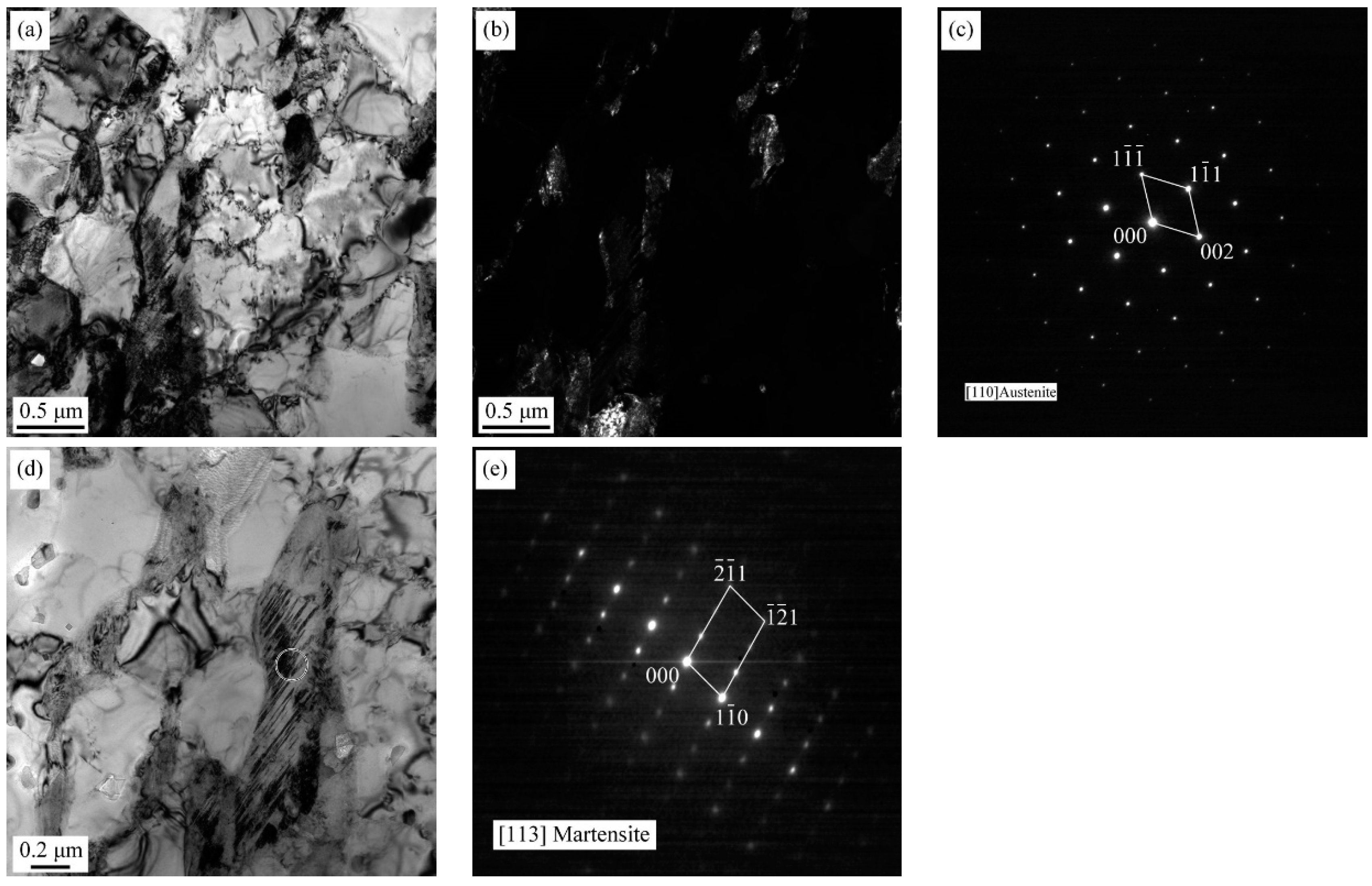
Figure 8.
TEM maps of retained austenite morphologies in IQ740. (a,c) Bright field map; (b,d) dark field map.
Figure 8.
TEM maps of retained austenite morphologies in IQ740. (a,c) Bright field map; (b,d) dark field map.
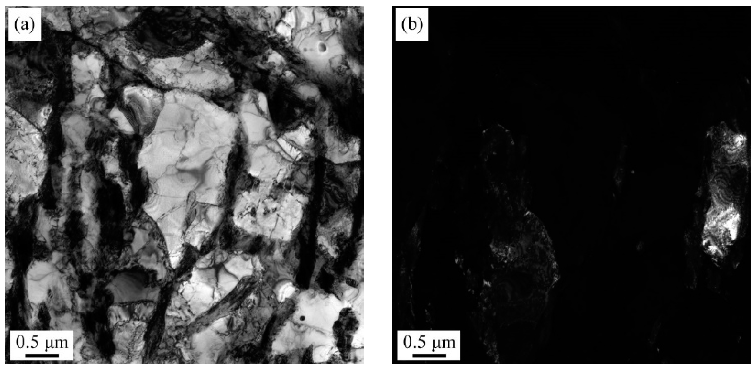

Figure 9.
Distributions of C and Mn in IQ700. (a) Surface scanning of C, (b) Surface scanning of Mn, (c) Line scanning of C and Mn, and (d) TEM-EDS analysis.
Figure 9.
Distributions of C and Mn in IQ700. (a) Surface scanning of C, (b) Surface scanning of Mn, (c) Line scanning of C and Mn, and (d) TEM-EDS analysis.


Figure 10.
Mechanical properties of experimental steels with different intercritical quenching temperatures. (a) Tensile strength and yield strength; (b) elongation; (c) strength-ductility balance; (d) −40 °C impact toughness.
Figure 10.
Mechanical properties of experimental steels with different intercritical quenching temperatures. (a) Tensile strength and yield strength; (b) elongation; (c) strength-ductility balance; (d) −40 °C impact toughness.


Figure 11.
The force-displacement curves of experimental steels with different intercritical quenching temperatures.
Figure 11.
The force-displacement curves of experimental steels with different intercritical quenching temperatures.

Figure 12.
Impact fracture morphologies of experimental steels with different intercritical quenching temperatures. (a,a1) IQ700; (b,b1) IQ720; (c,c1) IQ740.
Figure 12.
Impact fracture morphologies of experimental steels with different intercritical quenching temperatures. (a,a1) IQ700; (b,b1) IQ720; (c,c1) IQ740.

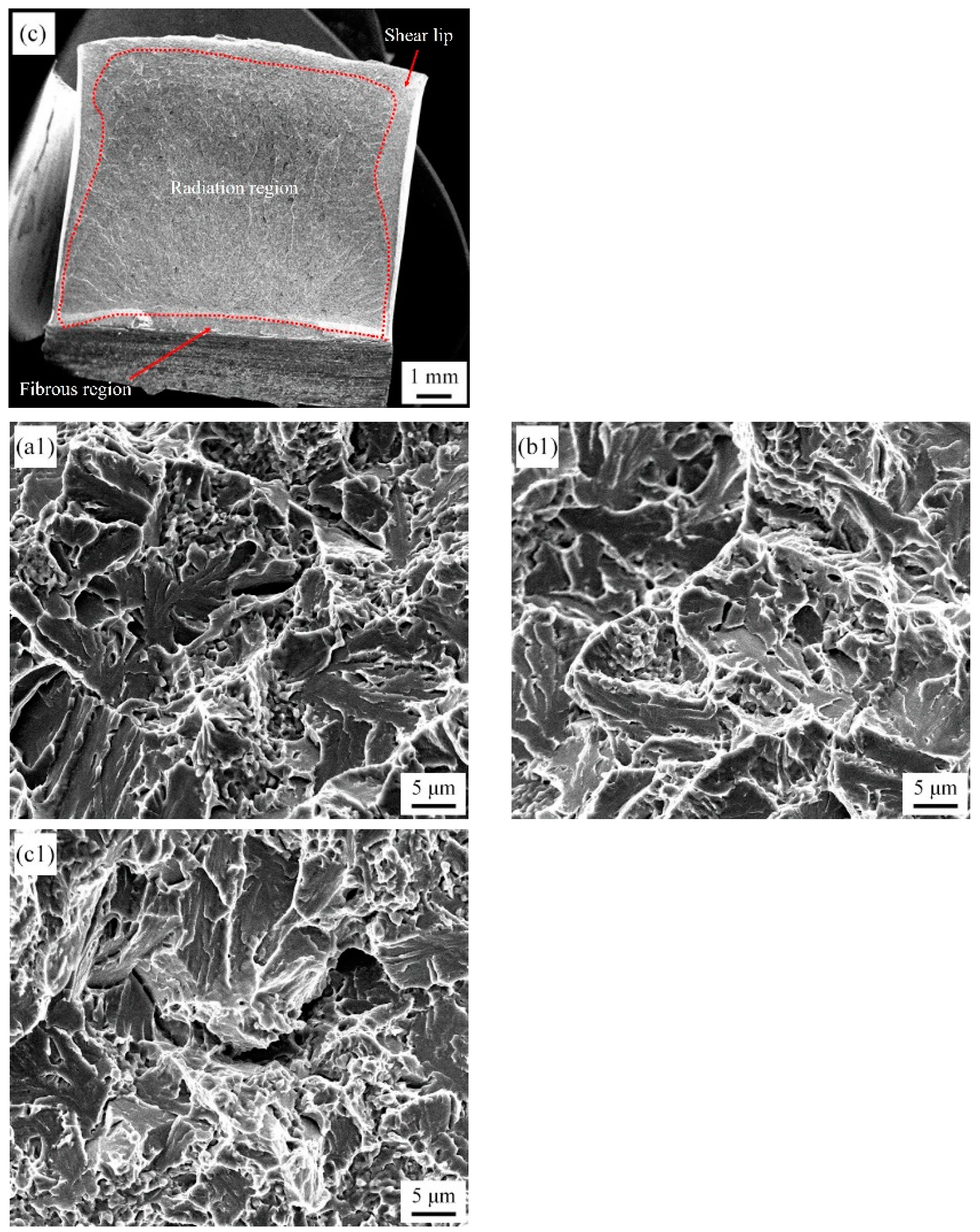
Figure 13.
EBSD results of the impact fracture crack tip for IQ740. (a) Inverse pole figure (IPF) map, (b) Band Contrast (BC) map.
Figure 13.
EBSD results of the impact fracture crack tip for IQ740. (a) Inverse pole figure (IPF) map, (b) Band Contrast (BC) map.
Disclaimer/Publisher’s Note: The statements, opinions and data contained in all publications are solely those of the individual author(s) and contributor(s) and not of MDPI and/or the editor(s). MDPI and/or the editor(s) disclaim responsibility for any injury to people or property resulting from any ideas, methods, instructions or products referred to in the content. |
© 2023 by the authors. Licensee MDPI, Basel, Switzerland. This article is an open access article distributed under the terms and conditions of the Creative Commons Attribution (CC BY) license (https://creativecommons.org/licenses/by/4.0/).
Share and Cite
MDPI and ACS Style
Huang, L.; Liu, J.; Deng, X.; Wang, Z. Achieving High Plasticity and High Toughness of Low-Carbon Low-Alloy Steel through Intercritical Heat Treatment. Metals 2023, 13, 1737. https://doi.org/10.3390/met13101737
AMA Style
Huang L, Liu J, Deng X, Wang Z. Achieving High Plasticity and High Toughness of Low-Carbon Low-Alloy Steel through Intercritical Heat Treatment. Metals. 2023; 13(10):1737. https://doi.org/10.3390/met13101737
Chicago/Turabian StyleHuang, Long, Jia Liu, Xiangtao Deng, and Zhaodong Wang. 2023. "Achieving High Plasticity and High Toughness of Low-Carbon Low-Alloy Steel through Intercritical Heat Treatment" Metals 13, no. 10: 1737. https://doi.org/10.3390/met13101737
Note that from the first issue of 2016, this journal uses article numbers instead of page numbers. See further details here.