
Ultrasonic Welding of Aluminum to Steel: A Review
1
School of Mechanical Engineering, Yangtze University, Jingzhou 434023, China
2
School of Mechanical and Automotive Engineering, South China University of Technology, Guangzhou 510640, China
3
School of Mechatronical Engineering, Beijing Institute of Technology, Beijing 100081, China
*
Author to whom correspondence should be addressed.
Metals 2023, 13(1), 29; https://doi.org/10.3390/met13010029
Submission received: 28 November 2022
/
Revised: 12 December 2022
/
Accepted: 20 December 2022
/
Published: 22 December 2022
(This article belongs to the Special Issue Microstructure and Mechanical Property Improvement of Welded Metal Joints)
Abstract
:As a solid-state bonding technology, ultrasonic welding (USW) has the characteristics of green energy saving and environmental friendliness. It is more suitable for joining dissimilar metals than other welding technologies. The aluminum-to-steel USWed joint has been widely used in the automotive and aviation industries. Currently, there is no review literature report on aluminum-to-steel USW. The main physical phenomena of the USW process include interface temperature increase, ultrasonic softening, plastic deformation, formation and growth of the IMCs, and dynamic recrystallization. Hence, the microstructures and mechanical properties of aluminum-alloy-to-low-carbon-steel, aluminum-alloy-to-stainless steel, and aluminum-alloy-to-galvanized-steel-joints by USW are reviewed. Moreover, the effect of interface temperature, interface plastic deformation, and interface macrostructure and microstructure is explored. Lastly, tensile-shear and fatigue strength of joints and numerical simulation of the USW process are also discussed. In addition, some new application types of aluminum-to-steel USW are introduced. Finally, the future trends of aluminum-to-steel USW with guidance are provided.
1. Introduction
In recent years, lightweight materials in the automotive and aviation industries have become the most efficient way to reduce environmental pollution and improve fuel efficiency [1]. It was reported that weight reduction in vehicles by 100 kg reduces fuel consumption by 0.6 L per 100 km and reduces CO2 emissions by 500 g per 100 km [2]. Aluminum alloy has become an increasingly popular steel replacement in the fabrication of vehicles due to its high strength-to-weight ratio, good formability, and recyclability [3,4]. Additionally, replacing steel with aluminum alloy in aerospace can reduce the high amount of aviation fuel. However, there are obvious differences in physical and metallurgical properties between aluminum alloy and steel. Welding defects, such as non-fusion and cracks, can occur in fusion welding. Moreover, brittle intermetallic compounds (IMCs), such as Fe3Al, FeAl, FeAl2, Fe2Al5, and FeAl3, can be formed at the interface of aluminum-to-steel joints [5,6], which seriously degrades the joint quality. Therefore, the high-quality joints of aluminum-to-steel are important to drive the light weight of the automotive and aviation sector. However, applying rivets increases automotive body weight, while conventional riveting methods’ joint quality is unstable [7]. Currently, self-piercing riveting (SPR) and resistance element welding (REW) could be considered potential joining technologies in aluminum-to-steel joints [8,9]. However, it is generally necessary to punch holes in the base metal before welding to obtain high-strength joints. Laser welding (LW) of aluminum-to-steel needs to control IMCs thickness while welding defects, such as collapse and splashing, can easily occur [10,11]. The major drawbacks of resistance spot welding (RSW) of aluminum and steel include high energy consumption, high induced residual stresses, and electrode wear, which make the joint quality difficult to control [12,13]. Friction stir welding (FSW) has the advantages of low heat input and effective control of IMCs growth [14,15]. However, it has a long welding time. As a solid-state joining technology, USW is more suitable for joining dissimilar metals since it does not require additional filler materials [16], has a shorter welding cycle and lower energy consumption [17,18], and welding fume and arc are not generated during the USW process [19,20]. Aluminum-to-steel USW has been applied to automotive and aviation lightweight. Therefore, USW is drawing more and more attention.
In the aluminum-to-steel USW process, the IMC is formed due to temperature increase and plastic deformation of the welding interface. The mechanical interlock is gradually formed under the interaction of welding pressure and ultrasonic softening, which can enhance the quality of joining [21,22]. Currently, there are many investigations on USWed aluminum-to-steel regarding aluminum-alloy-to low-carbon-steel, aluminum-alloy-to-stainless-steel, and aluminum-alloy-to-galvanized-steel, which are used in automotive and aviation lightweightmachinery. The main research direction is the microstructure formation mechanism at the interface and mechanical properties of the joint. In addition, the finite element method has reported little work on interface temperature rise and plastic deformation of aluminum-to-steel in the USW process. However, no review papers about USWed aluminum-to-steel joints have been published. Therefore, this paper reviews the parametric study, numerical simulation, and microstructure evolution mechanism of aluminum-to-steel USW. Moreover, the state-of-the-art on aluminum-to-steel USW is summarized. In addition, the future trends of aluminum-to-steel USW are provided to ensure guidelines for the research of automotive and lightweight aviation welding. Lastly, guidelines and valuable knowledge for the integration of aluminum and steel USW in lightweight materialsof the automotive and aviation industries are provided as a basis for future research directions in these fields.
2. Introduction of USW
2.1. Principle and Characteristics of USW
During the USW process, the welding pressure transfers the vibration energy from the sonotrode to the workpiece interface, resulting in plastic deformation and the gradual formation of the micro-joints. The micro-joints gradually expand to the welding interface as the welding process progresses. Thus, full bonding is achieved, resulting in atomic diffusion across the interface. As the input energy increases, the IMC thickness also increases. The main physical phenomena of the USW process include interface temperature increase, ultrasonic softening, plastic deformation, formation and growth of the IMCs, and dynamic recrystallization [23]. Figure 1 shows the schematic of the principle of USW.
The main parameters of USW are vibration amplitude, welding pressure, and welding time. The vibration amplitude affects the relative movement between workpieces. The welding pressure affects interface friction and plastic deformation inside the material (vacancy concentration), which then affects the metallurgical behavior of the interface and joint quality. The welding time (or heat input) affects the interface temperature, plastic deformation, and metallurgical bonding of the welding interface. The surface conditions (such as roughness or friction coefficient and galvanized coating) of workpieces affect the friction coefficient of the interface and microstructure evolution [24]. The geometry of the tool head affects all physical phenomena of the welding interface [25,26]. The influence mechanism for USW is outlined in Figure 2.
2.2. Advantages of USW
USW has the following advantages:
- (1).
- (2).
- No water cooling or shielding gas, surface cleaning, and the addition of filler materials are required. Moreover, USW is insensitive to surface oxide film [16].
- (3).
- (4).
- (5).
- (6).
Figure 3.
(a) USW robotic; (b) automotive closure panel [28].
Figure 3.
(a) USW robotic; (b) automotive closure panel [28].
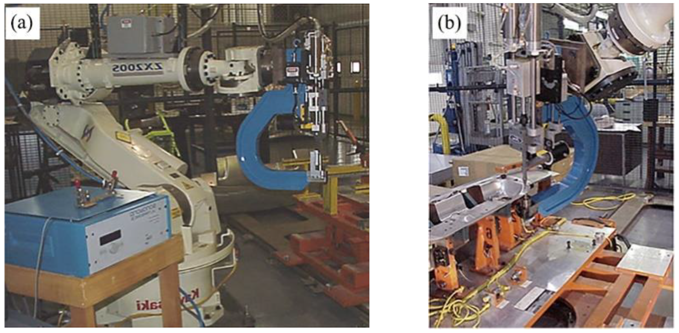
Due to the abovementioned advantages, aluminum-to-steel USW has been applied to automotive and aviation lightweight material, as shown in Figure 3b. USW technology is expected to be applied to a large area.
2.3. System of Aluminum-to-Steel USW
Wedge reed and lateral drive systems are commonly employed configurations in ultrasonic metal welders for joining aluminum-to-steel [29,30]. The two systems have similar ultrasonic systems, including transducers and boosters (Figure 4a). The transducer transforms the electrical energy into mechanical energy (vibration), and the booster is used for the vibration amplitude amplification and transfer to the sonotrode. The wedge-reed system (Figure 4b) is characterized by a low vibration amplitude, a large welding pressure, and a long welding time (typically over 2 s). The lateral drive system is characterized by a thicker booster (Figure 4c), a large vibration amplitude, a low welding pressure, and a shorter welding time. The lateral drive system measures welding parameters (such as welding pressure and vibration amplitude) more accurately than the wedge reed system [30].
3. Status of Experimental Research on Aluminum to Steel USW
3.1. Interface Temperature of Aluminum to Steel USW
The metallurgical reaction of USW is determined by the interface temperature. Currently, the interface temperature is measured by an infrared camera or a thermocouple embedded between the aluminum and steel sheets. Haddadi et al. [31,32] carried out the USW experiment of 6111 aluminum alloy to DC04 steel using a wedge-reed welder. Two thermocouples were simultaneously placed to measure the temperature of the edge and center of the welding interface, as shown in Figure 5. According to their results, the temperature of the interface edge can be successfully measured during welding, while the maximum temperature reaches approximately 500 °C. However, the thermocouple in the center of the interface was damaged due to severe plastic deformation. Nevertheless, the peak interface temperature close to 550 °C was recorded at the end of the welding process, as shown in Figure 6.
Lin et al. [21] reported that the peak temperature at the edge of the welding interface of 5052 aluminum alloy to IF steel reached 500 °C. Haddadi et al. [33] measured the temperature field of the cross-section of an aluminum-to-steel joint with an infrared camera (Optris PI 1M). The authors found that the material temperature under the sonotrode tip sharply increased, as shown in Figure 7.
Wang et al. [34] found no obvious changes in the interface temperature by changing the specimen placed direction (vertical to or parallel to the vibration direction), since the frictional heat between the sonotrode and the workpiece has not changed, as shown in Figure 8. Satpathy et al. [22] reported that the interface temperature of the AA3003 aluminum alloy/304 stainless steel joint was significantly increased by inserting the Cu interlayer. Moreover, the peak temperature of dissimilar joints with interlayer reached its maximum of 592 °C due to increased friction caused by the Cu interlayer.
For aluminum-alloy-to-galvanized steel USW, the temperature increase at the interface differs from that of aluminum alloy to low-carbon steel due to Zn coating melting. USW of 6111-T4 aluminum-alloy-to-soft hot dipped Zn coated steel (DX56-Z), 6111-T4 aluminum alloy-to-hard galvannealed Zn coated steel (DX53-ZF), and 6111-T4 aluminum-alloy-to-DC04 steel were carried by Haddadi et al. [33,35]. Their result shows that the interface temperature of aluminum-to-DC04 steel was roughly 100 °C higher than that of aluminum-to-galvannealed steel since the power delivery increased with resistance at the workpiece faying surfaces and higher heat generation in the welding process of DC04 steel and aluminum alloy. The interface temperature of 6111-T4 to DX53-ZF was about 10–60 °C lower than that of 6111-T4 to DX56-Z (Figure 9) because the zinc coating thickness of DX56-Z was thinner than that of DX53-ZF. Consequently, higher plastic deformation was generated during the 6111-T4-to-DX53-ZF welding process. In addition, the interface temperature of aluminum alloy to galvannealed steel exceeds the Al-Zn eutectic melting point, resulting in localized melting at the welding interface. The authors concluded that a high strain rate caused a decrease in the Al-Zn eutectic metal point during welding. Similar results were reported by Patel et al. [36], Haddadi et al. [32], Macwan et al. [37], Mirza et al. [38], Macwan et al. [5] and Satpathy et al. [22]. According to Gunduz et al. [39], the Al-Zn eutectic melting point decreased due to ultrasound irradiation, which reduced the temperature required for interfacial metallurgy of galvanized steel and aluminum alloy. Haddadi et al. [32] measured the temperature distribution across the lap area close to the welding tip edge of joints of 6111-T4 to DX56-Z and 6111-T4 to DX53-ZF by an infrared camera. The authors observed temperature asymmetry distribution, as shown in Figure 10.
3.2. Plastic Deformation of Aluminum to Steel USW
Haddadi et al. [32] obtained 3D visualization of the aluminum side deformation of 6111 aluminum alloy-to-DC04 steel USW joint, as shown in Figure 11. The pressing displacement of the sonotrode reduces the thickness of the aluminum sheet in the welding zone with an increase in the welding time. Moreover, the material extruded at the sonotrode tip edge occurred at the later welding stage.
The plastic deformation of aluminum-to-steel joints can be used to understand the interface metallurgical mechanism and qualitatively evaluate the welding quality. The welding cross-section of 304 stainless steel to 3003 aluminum alloy under different welding energy (Figure 12) was obtained by Shakil et al. [40]. The sonotrode exerts the shear force on the material surface by friction at the initial welding stage. The repetition of sliding and friction produced by the sonotrode produces plastic deformation on the material surface under the sonotrode tip. Then, the workpiece material flows to the knurl gap of the sonotrode and the anvil. The tips of the sonotrode and the anvil completely penetrated the workpiece with the expansion of the plastic deformation zone.
Satpathy et al. [22] carried out USW experiments of 304-stainless-steel-to-AA3003 aluminum-alloy and AA3003-aluminum-alloy-to−304-stainless-steel. The authors found many cracks on the welding interface when the stainless steel was an upper workpiece (Figure 13a). Furthermore, the plastic deformation of stainless steel as a lower workpiece was insufficient (Figure 13b). Mechanical interlocking also occurred at the interface, enhancing the joint quality.
3.3. Microstructure of Aluminum-to-Steel USW
3.3.1. Interfacial Diffusion
Atomic diffusion and dynamic recrystallization of the welding interface are critical metallurgical reactions in aluminum-to-steel USW. The welding quality is determined by forming IMC and dynamic recrystallization grains. Lin et al. [21] described the bonding mechanism of the interface in the 5052 aluminum alloy and low-carbon steel joint. At the initial USW process, adhesive wear starts when steel and aluminum alloy have sliding contact, and thereafter, a thin layer of Al is attached onto the surface of the steel while the wear of Al base metal is continued owing to the sliding. As the welding time increased, voids and gaps occurred at the bonding interface disappeared with softened Al base metal to achieve bonding between steel and aluminum. With longer welding time to 2.5 s, IMC formed at the bonding interface.
Watanabe et al. [41] found that IMC was not observed at the welding interface of the A1050-pure-aluminum-to-SS400-stainless-steel joint made using the welding time of 2.5 s. As the welding time increased to 3 s, the IMC was composed of Fe2Al5 at the welding interface. Lin et al. [21] observed only the Fe2Al5 phase in the IMC at the welding interface of 5052 aluminum alloy and low-carbon steel. However, according to EDS results [34], the IMC of 6022 aluminum alloy and DP600 steel interface was mainly the Al13Fe4 phase.
Prangnell et al. [42] used scanning electron microscope (SEM) and transmission electron microscope (TEM) to identify a dual-layer IMC structure in an aluminum-to-steel joints interface, with a continuous FeAl3 phase near the aluminum side and a large irregular Fe2Al5 phase region near the steel side, as shown in Figure 14. Haddadi [31] found FeAl phase and Al2O3 in the IMC layer. The presence of FeAl3 phase and Fe3Al phases at the welding interface of 6061 aluminum alloy-to-ASTM A36 steel was reported by Mirza et al. [38,43].
Some researchers carried out electron backscatter diffraction (EBSD) to observe the IMC profile. Prangnell et al. [42] found that the grain structure within the aluminum side of the weld becomes uniform and equiaxed, and a relatively high density of subgrain boundary was observed at the steel side. Xu et al. [44] reported that Fe2Al5 and FeAl3 phases developed columnar grain structures during welding (Figure 15a). The Fe2Al5 phase developed a fiber texture with the [001] direction preferentially orientated in the direction of columnar growth (Figure 15b). Moreover, the FeAl3 phase also had a weak fiber texture, with its [010] direction normally aligned to the joint interface (Figure 15c).
Fujii et al. [45] found no significant changes in texture far away from the welding zone. In addition, the {111} slip planes and <110> slip directions of the grain appeared in the welding zone, as shown in Figure 16. This can be attributed to the shear deformation of the aluminum alloy surface caused by friction between the aluminum alloy and the stainless steel.
For USW of aluminum alloy and galvanized sheet, the coating on the galvanized steel surface will prevent the atom diffusion between Fe and Al. Haddadi et al. [32] found that the Fe2Al(5-x)Znx(0 < x < 1) inhibition intermetallic layer on the DX56-Z surface can be affected by the formation of Fe2Al5 phase at the interface. Haddadi [3] found that aluminum α phase dendrites formed at 3.0 s and very-fine lamellae eutectic structure in the inter-dendritic regions in the 6111-T4 aluminum alloy-to-DX56-Z-steel interface. Moreover, the 6111-T4 aluminum alloy-to-DX53-ZF interface formed brittle Fe-Zn IMC by the diffusion of Zn-rich liquid into high-angle boundaries of the steel. Mirza et al. [38] reported Al-Zn eutectic structure and FeAl3 phase at the 6061-T6 aluminum alloy-to-hot-dip galvanized HSLA steel interface, as shown in Figure 17. Macwan et al. [5] carried out USW of 6111-T4-aluminum-alloy-to-hot-dip-galvanized-HSLA-steel. The authors found that the diffusion layer was mainly composed of an Al-Zn eutectoid phase and an Al-Zn eutectic phase when the welding energy was 1000 J. Then, a very thin FeAl3 phase was formed at the welding energy of 2000 J. The percentage of Zn element in the interface diffusion layer decreased with the welding energy from 2000 J to 3000 J.
3.3.2. IMC Formation Mechanism
Prangnell et al. [42] determined the IMC thickness via atomic diffusion rate during aluminum-to-steel USW. Due to the high-frequency mechanical vibration, an increase in the atomic diffusion rate and IMC growth rate was caused by the vacancies, dislocations, fine-grained structures, and substructures at the interface. Haddadi [31] also found that the growth rate of IMC through isothermal annealing of the workpiece after welding was much lower than the growth rate of IMC during the USW process.
Different IMC with different Gibbs free energies can obtain various interfacial metallurgical reactions. Prangnell et al. [42] reported that the Fe2Al5 phase formed before any other iron aluminide phase in the welding interface due to the kinetic growth advantage of Fe2Al5 over other iron aluminide phases. Xu et al. [44] observed that the IMC comprises the Fe2Al5 phase through selected area diffraction (SADP) at the initial welding stage. Moreover, the Fe2Al5 phase was found to be the first IMC phase to nucleate. Haddadi et al. [32] found that preferential formation of the FeAl3 phase was expected, since it is characterized by the highest negative free Gibbs energy of formation. In addition, the Fe2Al5 phase has the largest fraction in the IMC layer due to higher kinetic growth and a favored crystallographic habit orientation with ferrite, facilitating the nucleation of the Fe2Al5 phase. Mirza et al. [38,43] reported that the formation of the first phase was the FeAl3 phase, while FeAl3 and Fe phases react with each other to form other phases.
Haddadi [3] reported that a thin and continuous layer of Fe2Al5 phase occurred in the diffusion layer due to the substitution of zinc atoms by the aluminum in the Fe2Al(5-x)Znx(0 < x < 1) inhibition intermetallic layer, as shown in Figure 18. Macwan et al. [5,37] found that the interface diffusion layer grew towards the aluminum sheet after forming the continuous diffusion layer. This formation can be attributed to the closer melting point of Zn to that of Al, smaller atomic radius of Zn than that of Al (but higher than that of Fe), and much higher lattice diffusivity of Zn in Al than that of Zn in Fe below the melting point of Al.
Xu et al. [44] found a higher solubility in the IMC layer of the Zn element in the aluminum alloy than that of other alloy elements at the welding interface of the AA7055-aluminum-alloy-to-DC04-steel-joint. In addition, the authors predicted the formation of IMC at the interface by the CALPHAD method (Figure 19). Furthermore, the authors found that FeAl3 and Fe2Al5 phases were the most stable IMCs at the welding interface. Lastly, FeAl2 and FeAl phases were expected as equilibrium phases at the welding interface.
3.3.3. Recrystallization Microstructure
Haddadi et al. [35] found that a thin layer of grain structure formed on the aluminum side at the interface of aluminum-alloy-to-DC04-steel. This structure was accompanied by increased high-angle boundary density in a short welding time of 0.4 s. Moreover, the grains on the aluminum side should have increased with the welding time while the density of high-angle grain boundaries decreased. However, many low-angle grain boundaries were formed at the welding interface of aluminum-alloy-to-galvanized-steel. Moreover, no recrystallization organization was found on the aluminum side near the welding interface, as shown in Figure 20. Diffusion of the molten Zn through the high-angle boundaries into the steel side was observed by Haddadi et al. [33]. However, Becker et al. [46] reported no diffusion of molten Zn into the steel sheet by the grain boundary at the welding interface of 6005A-aluminum-alloy-to-galvanized-HCT980X-steel.
3.4. Strength and Failure of Aluminum-to-Steel Ultrasonic Welded Joint
Watanabe et al. [41] reported that, with the welding pressure of 588 N, the strength of the joint with shorter welding time gradually increased and sharply decreased with higher welding time due to the formation of brittle IMC. Tsujino et al. [47] found that the strength of the 5052-aluminum-alloy-to-stainless-steel-joint was relatively similar to the strength of the aluminum alloy specimen within an amplitude of 17–27 μm. Wang et al. [34] found that the joint strength was higher than that parallel to the tension direction when the vibration direction of the sonotrode was vertical to the tension direction.
Haddadi et al. [35] found that the joint failure occurred by cracking through the interface of the diffusion layer and the FeAl phase. Mirza et al. [43] and Xu et al. [44] reported that joint failure occurred in the FeAl3 phase due to its lower toughness than other IMCs.
Prangnell et al. [42] and Haddadi et al. [32] demonstrated a change in failure behavior from interfacial failure to nugget pull-out mode and then back to interfacial failure for joints produced with an increase in the welding time, as shown in Figure 21. Haddadi et al. [35] investigated the influence of energy on the strength of aluminum-to-steel joints and found that lower energy reduces the welding zone and joint strength. Wang et al. [34] found that vibrational direction influences the welding strength by changing micro-bond alignment when interface failure was observed. The authors concluded that such influences did affect the welding strength when nugget pull-out occurred. Interface failure and transverse-through-thickness failure (TTT) occurred when the tensile strength was higher than 3200 N. On the other hand, Zhao et al. [48] found that the failure mode of the aluminum-to-steel joint was interface failure or TTT when the tensile strength was lower than 3200 N.
Nishihara et al. [49] obtained the relationship between the tensile strength of the A5052-H24-aluminum-alloy-to-SS400-mild-steel-joint, tool head geometry, and welding pressure, as shown in Figure 22. The strength of the joint welded using a C-tip (the sonotrode-side tip face is smooth and has a spherical radius of about 200 mm, and the anvil-side tip face is smooth and flat) increases with the clamping force. The strength of the joint welded using a K-tip (the geometry of both the sonotrode-side tip and anvil-side tip was flat and the tip surface has a knurl with a pyramid shape) decreases with an increase in the clamping force. The strength of the joint welded using the C-tip was higher than that of the K-tip under the welding pressure of 1470 N. However, the C-tip will lead to the fracture of an aluminum-to-steel joint under high clamping force.
During the welding process of 6111-aluminum-alloy-to-galvanized-steel, the molted Zn and Al-Zn eutectoid/eutectic produced a brazing effect around the nugget edge and enhanced the joint quality [5,38]. The joint failure mode changed from interface failure to base metal failure and then to nugget edge failure with increased welding energy, as shown in Figure 23. Haddadi et al. [35] and Patel et al. [36] showed that welding interface failure was observed in aluminum-alloy-to-galvanized-steel-joints. Patel et al. [36] reported that the aluminum-alloy-to-galvanized-steel joint fracture occurred between Al-Zn eutectic structure and the IMC layer. Haddadi et al. [3,32] found that the fracture of aluminum alloy and galvanized steel joint occurred between the Al-Zn eutectic structure in a short welding time. Moreover, the authors concluded that the failure occurred at the interface of the melted Zn layer and the steel substrate with an increase in the welding time, as shown in Figure 24.
As reported by Haddadi [31], a small amount of Zn and Si elements in the aluminum alloy will inhibit the formation of IMC at the aluminum-to-steel interface. Watanabe et al. [41] found that the Mg element in the aluminum alloy will be segregated to form MgO around the dimple, decreasing the welding quality. In addition, the authors used 1.2 mm of commercially pure aluminum as an insert metal and found that the joint strength was three times as high as without an insert metal. Nishihara et al. [49] used pure aluminum of 0.1 mm and 1.2 mm thickness as insert metal to obtain joints with lower strength than those without insert metal. However, using pure aluminum 0.5–0.8 mm thick as insert metal increased the joint strength by 25% compared to the strength of joints without insert metal (Figure 25a). The joints with insert metal thickness of 0.5–0.8 mm occurred in pull-out failure mode (Figure 25b).
USW experiments of Al/Mg/Al-clad-sheet-to-HSLA-steel and clad-sheet-to-galvanized-HSLA-steel were carried out by Macwan et al. [37]. Their result showed that the strength of the aluminum-to-steel interface was higher than the strength of the aluminum-to-magnesium interface. Moreover, the clad-sheet-to-Zn-coated-steel joint strength was higher than the clad-sheet-to-bare-steel joint. The failure occurred at the Al/Mg and aluminum-to-steel interfaces of the clad-sheet-to-HSLA-steel joint (Figure 26a, b). On the other hand, the failure of the clad-sheet-to-galvanized-steel joint occurred at the Al/Mg interface (Figure 26c,d).
According to the abovementioned investigations, the evaluation of the strength of the aluminum-to-steel joint is an important component of welding quality and essential for their real-life application. Currently, tensile-shear, U-tensile, and T-peel tests are widely employed to evaluate USWed aluminum-to-steel joints’ mechanical behaviors. The highest welding strength of various USWed aluminum-to-steel joints is shown in Table 1.
3.5. Fatigue Strength of Aluminum-to-Steel Ultrasonic Welded Joint
Macwan et al. [5] obtained the S-N curve of 6111 aluminum alloy-to-HSLA steel joint with the fatigue stress ratio of R = 0.2 and frequency of 50 Hz, as shown in Figure 27. The fatigue life of the welded joint made at a welding energy of 2000 J was higher than that of the welded joint at 1000 J. Furthermore, the fatigue limit for the welded joints made at 2000 J and 1000 J welding energy was 0.5 kN. In addition, the cyclic load at which the failure mode changed from the TTT fracture to the interfacial failure increased with the welding energy. Mirza et al. [38] studied the fatigue failure behavior of 6061-aluminum-alloy-to-ASTM-A36-steel joint. The failure mode of the aluminum-alloy-to-ASTM-A36-steel joint exhibited TTT at high cycle loads and a mixture of TTT and interface failure at low cycle loads.
4. Modeling of Aluminum-to-Steel USW
In the USW process of aluminum and steel, the temperature increase at the interface center, and the plastic strain of the material cannot be measured by the traditional method because the severe plastic deformation of the interface is relatively large in a short welding time. Therefore, the numerical simulation of the USW process of aluminum-to-steel is mainly used to predict the temperature field at the interface and the plastic deformation distribution of the material.
Jedrasiak et al. [51] established a finite element 3D model of the temperature field in USW of aluminum and steel, as shown in Figure 28. The heat source in the model was derived from ultrasonic electric power, and the simulated temperature at the interface center was 520 °C at the welding time of 1 s (Figure 29), which was approximately 10% higher than the temperature obtained from the thermocouple.
Jedrasiak et al. [52] simulated the interfacial plastic strain distribution in aluminum-to-steel USW. The plastic deformation of the specimen/specimen interface only occurs on the aluminum side at the end of welding due to the ultrasonic softening of aluminum alloy. The plastic deformation of the material near the welding zone takes place at strain rates on the order of 1000 s−1. Moreover, the plastic strain rate gradually decreases far from the welding interface, as shown in Figure 30. A higher plastic strain rate in the welding zone promotes the diffusion between Al and Fe.
5. New Application of Aluminum-to-Steel USW
5.1. Perpendicular Ultrasonic Welding Technology
Munoz-Guijosa et al. [53] proposed perpendicular ultrasonic welding technology to obtain the high-strength-steel-sheet-to-A2017-T4-aluminum-alloy joint and the high-strength-steel-sheet-to-A6061-T4-aluminum-alloy joint. This technology is similar to RSW and employs a sonotrode tip with a diameter of 2.9 mm. The ultrasonic field density transmission path during welding is also similar to the current density channel of RSW. The obtained results showed that the temperature measured at less than 1 mm from the welding interface did not exceed 135 °C, and no IMC layer had been detected. The tensile-shear strength of the aluminum-to-steel joint was close to 76 MPa, i.e., close to the strength of the base metal Al, indicating a high-quality aluminum-to-steel joint. The joining technology could be used successfully for industrial applications using the available spot-welding tooling and operational procedure, as shown in Figure 31.
5.2. Multi-Spot Ultrasonic Welding Technology
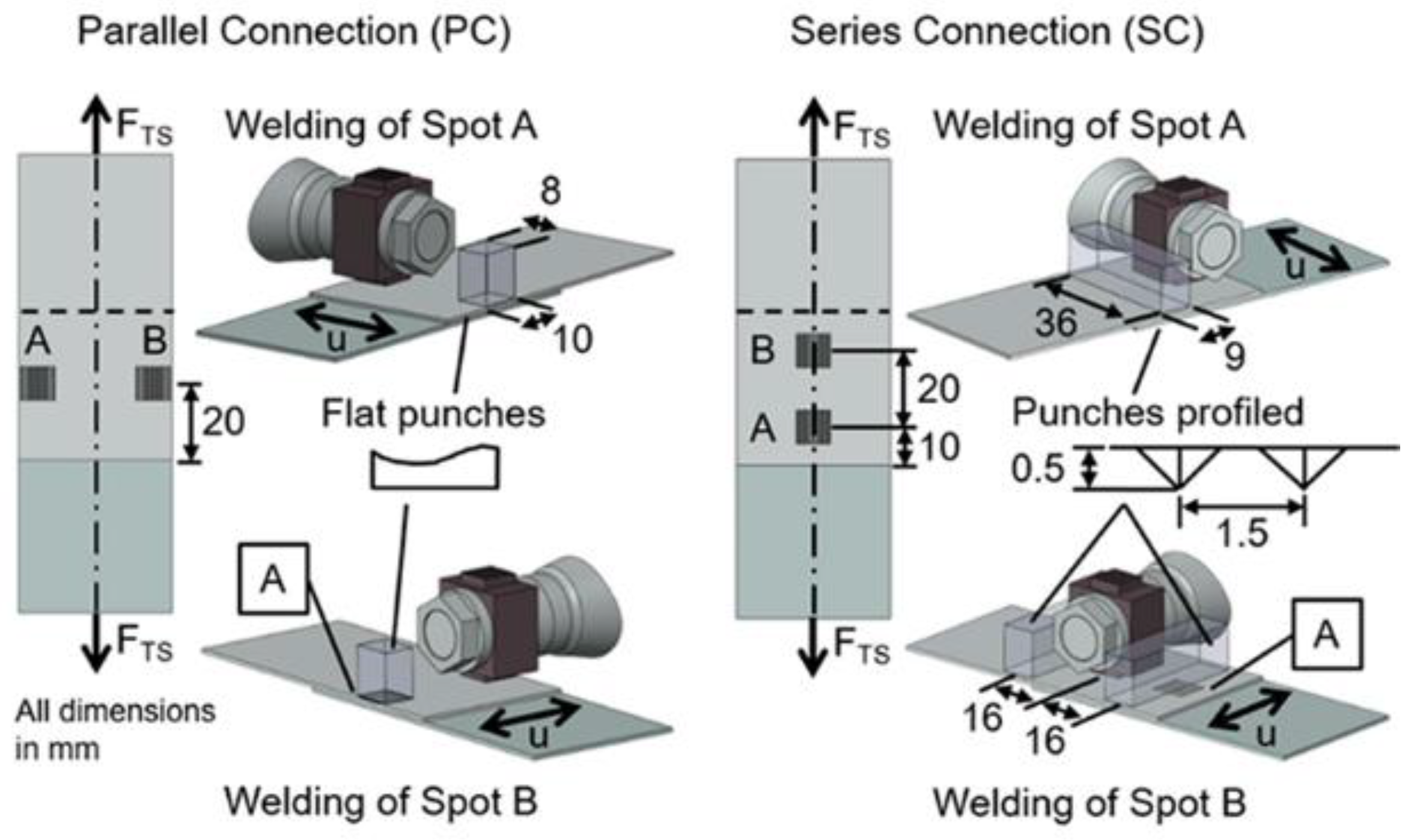
Becker et al. [46] designed a multi-spot ultrasonic welding system, which was achieved by designing series or parallel welding joints at aluminum and steel lap zones, and an additional clamping punch was used to protect previously welded joints during welding, as shown in Figure 32. The welding system carries out a multi-point ultrasonic welding experiment of 0.9 mm thick AA6005A-T4 aluminum alloy and 1.0 mm thick HCT980X steel. The high-quality aluminum-to-steel multi-spot joints can be obtained by selecting suitable welding process parameters. The authors found that the welding energy, vibration amplitude, and clamping force of series weld joints were higher than those of parallel weld joints. The authors concluded that the difference in strength between the two was related to the different positions of the weld spots and additional clamping punches as well as the geometry of the additional clamping punch.
6. Conclusions and Future Perspectives
This paper mainly focuses on the review of USW of aluminum-alloy-to-low-carbon-steel, aluminum-alloy-to-stainless-steel, and aluminum-alloy-to-galvanized-steel. Moreover, this paper reviews the advance in aluminum-to-steel USW, including interface temperature measurement, microstructure, joint strength, and finite element simulation of the USW process. The significant conclusions and research directions in the future are as follows:
- (1).
- The steel specimens in USWed aluminum-to-steel are mainly using low-carbon steel, low-carbon galvanized steel, and SS304 stainless steel. In the future, other welding heat sources, such as RSW and LW, can be combined with aluminum alloy and high-strength steel USW to obtain high-quality joining.
- (2).
- During the USW process of aluminum and steel, the interface temperature and IMC layer thickness increased with the vibration amplitude. The welding quality gradually improved with increased clamping force, but excessive clamping force can result in cracks and other defects in the workpiece. The IMC layer thickness increased, and its composition changed with an increase in the welding time. There are very few reports to date on the parametric optimization of the aluminum-to-steel USW for improving the joint quality. Optimizing the tool head geometry and welding parameters of aluminum-to-steel USW is a research direction in the future.
- (3).
- The investigation of the USW process by the finite element method was mainly conducted to reveal the macro interface temperature increase and plastic deformation mechanism. In the future, the simulation of nano-scale plastic deformation of the welding interface and ultrasound field distribution in the specimens will help further reveal the welding mechanism of USW. In addition, molecular dynamics simulation of diffusion and atomic migration of the welding interface is a significant research direction.
- (4).
- In the USW process of aluminum-to-steel, the main IMCs produced by diffusion are Fe2Al5, FeAl3, and FeAl at the aluminum-to-steel interface, which are all brittle IMC. For USW of aluminum alloy and galvanized sheet, the coating on the galvanized steel surface will prevent the atom diffusion between Fe and Al. Consequently, the growth mechanism of predicting and controlling IMC by simulation represents a significant research direction. In addition, deformation and welding defects easily occur since the steel has large stiffness. In the future, controlling the shape and microstructure can improve the quality of aluminum-to-steel USW.
Author Contributions
Conceptualization, writing—review and editing, supervision, H.L.; writing—original draft preparation, data curation, investigation, C.Z.; investigation, data curation, Q.L.; investigation, C.H.; funding acquisition, K.Z. All authors have read and agreed to the published version of the manuscript.
Funding
This research is supported by the National Natural Science Foundation of China (51605103) and Key Projects of Science and Technology Research Plan of Hubei Provincial Department of Education (D20221306).
Institutional Review Board Statement
Not applicable.
Informed Consent Statement
Not applicable.
Data Availability Statement
Not applicable.
Conflicts of Interest
The authors declare no conflict of interest.
References
- Baek, S.; Go, G.Y.; Park, J.W.; Song, J.; Lee, H.C.; Lee, S.J.; Lee, S.; Chen, C.; Kim, M.S.; Kim, D. Microstructural and interface geometrical influence on the mechanical fatigue property of aluminum/high-strength steel lap joints using resistance element welding for lightweight vehicles: Experimental and computational investigation. J. Mater. Res. Technol. 2022, 17, 658–678. [Google Scholar] [CrossRef]
- Wu, C.S.; Lu, X.Q.; Su, H.; Shi, L. Research progress in dissimilar friction stir welding of aluminium/magnesium alloys. J. Mech. Eng. 2020, 56, 4–16. (In Chinese) [Google Scholar]
- Haddadi, F. Microstructure reaction control of dissimilar automotive aluminium to galvanized steel sheets ultrasonic spot welding. Mater. Sci. Eng. A 2016, 678, 72–84. [Google Scholar] [CrossRef]
- Wang, T.; Sinha, S.; Komarasamy, M.; Shukla, S.; Williams, S.; Mishra, R.S. Ultrasonic spot welding of dissimilar Al 6022 and Al 7075 alloys. J. Mater. Process. Technol. 2020, 278, 116460. [Google Scholar] [CrossRef]
- Macwan, A.; Kumar, A.; Chen, D.L. Ultrasonic spot welded 6111-T4 aluminum alloy to galvanized high-strength low-alloy steel: Microstructure and mechanical properties. Mater. Des. 2017, 113, 284–296. [Google Scholar] [CrossRef]
- Matsuda, T.; Ogaki, T.; Hayashi, K.; Iwamoto, C.; Nozawa, T.; Ohata, M.; Hirose, A. Fracture dominant in friction stir spot welded joint between 6061 aluminum alloy and galvannealed steel based on microscale tensile testing. Mater. Des. 2022, 213, 110344. [Google Scholar] [CrossRef]
- Zhao, Y.Q.; Zhao, Y.J.; Liu, Z.; Lin, Z.C.; Dong, C.L. Control of temperature field, microstructure and mechanical properties of variable rotation speed refill friction stir spot welded high strength aluminum alloys. Trans. China Weld. Inst. 2022, 43, 50–55. (In Chinese) [Google Scholar]
- Ling, Z.X.; Li, Y.; Luo, Z.; Feng, Y.Q.; Wang, Z.M. Resistance element welding of 6061 aluminum alloy to uncoated 22MnMoB boron steel. Mater. Manuf. Process. 2016, 31, 2174–2180. [Google Scholar] [CrossRef]
- He, G.Z.; Lou, M.; Ma, Y.W.; Li, Y.B. Simulation on mechanical properties of resistance element welding of aluminum and steel. J. Shanghai Jiao Tong Univ. 2019, 53, 616–623. (In Chinese) [Google Scholar]
- Wang, X.H.; Gu, X.Y.; Sun, D.Q. Research on interface characteristic of laser welding joints of steel/aluminum dissimilar materials. J. Mech. Eng. 2017, 53, 26–33. (In Chinese) [Google Scholar] [CrossRef]
- Shin, S.; Nam, S.; Yu, J.; Park, J.; Kim, D. Ultrasonic metal welding of multilayered copper foils to nickel-plated copper sheet in lithium-ion battery cell. Metals 2021, 11, 1195. [Google Scholar] [CrossRef]
- Feng, M.N.; Luo, Z. Interface morphology and microstructure of high-power ultrasonic spot welded Mg/Al dissimilar joint. Sci. Technol. Weld. Join. 2018, 24, 63–78. [Google Scholar] [CrossRef]
- Gullino, A.; Matteis, P.; D’Aiuto, F. Review of aluminum-to-steel welding technologies for car-body applications. Metals 2019, 9, 315. [Google Scholar] [CrossRef]
- Zhou, L.; Liu, S.; Min, J.; Qin, Z.W.; He, W.X.; Song, X.G.; Xu, H.B.; Feng, J.C. Interface microstructure and formation mechanism of ultrasonic spot welding for Al–Ti dissimilar metals. Int. J. Min. Met. Mater. 2021, 28, 1506–1514. [Google Scholar] [CrossRef]
- Sun, Y.M.; Gong, W.B.; Feng, J.C.; Lu, G.P.; Zhu, R.; Li, Y.P. A review of the friction stir welding of dissimilar materials between aluminum alloys and copper. Metals 2022, 12, 675. [Google Scholar] [CrossRef]
- Cai, W.; Daehn, G.; Vivek, A.; Li, J.; Khan, H.; Mishra, R.S.; Komarasamy, M. A state-of-the-art review on solid-state metal joining. J. Manuf. Sci. Eng. 2019, 141, 031012. [Google Scholar] [CrossRef]
- Ao, S.S.; Zhang, W.; Li, C.J.; Oliveira, J.P.; Zeng, Z.; Luo, Z. Variable-parameter NiTi ultrasonic spot welding with Cu interlayer. Mater. Manuf. Process. 2020, 36, 599–607. [Google Scholar] [CrossRef]
- Li, H.; Zhou, K.; Cao, B.; Zhang, J. Analysis of welding interface and joint properties of high power ultrasonic welding of aluminum alloy. J. Mech. Eng. 2021, 57, 87–95. (In Chinese) [Google Scholar]
- Ni, Z.L.; Yang, J.J.; Ye, F.X. Microstructure and mechanical properties of copper to nickel ultrasonic spot welds. Mater. Sci. Eng. A 2020, 796, 140207. [Google Scholar] [CrossRef]
- Ma, Q.C.; Ma, J.Y.; Zhou, J.L.; Ji, H.J. Intrinsic dependence of welding quality and recrystallization on the surface-contacted micro-asperity scale during ultrasonic welding of Cu–Cu joints. J. Mater. Res. Technol. 2022, 17, 353–364. [Google Scholar] [CrossRef]
- Lin, J.Y.; Nambu, S.; Koseki, T. Evolution of bonding interface during ultrasonic welding between steel and aluminium alloy. Sci. Technol. Weld. Join. 2019, 24, 83–91. [Google Scholar] [CrossRef]
- Satpathy, M.P.; Patel, B.; Sahoo, S.K. Exploration of bonding phenomenon and microstructural characterization during high-power ultrasonic spot welding of aluminum to steel sheets with copper interlayer. Ain Shams Eng. J. 2019, 10, 811–819. [Google Scholar] [CrossRef]
- Li, H.; Cao, B. Effects of welding pressure on high-power ultrasonic spot welding of Cu/Al dissimilar metals. J. Manuf. Process. 2019, 46, 194–203. [Google Scholar] [CrossRef]
- Zhang, C.; Li, L. A friction-based finite element analysis of ultrasonic consolidation. Weld. J. 2008, 87, 187–194. [Google Scholar]
- Komiyama, K.; Sasaki, T.; Watanabe, Y. Effect of tool edge geometry in ultrasonic welding. J. Mater. Process. Technol. 2016, 229, 714–721. [Google Scholar] [CrossRef]
- Lee, D.; Cai, W. The effect of horn knurl geometry on battery tab ultrasonic welding quality: 2D finite element simulations. J. Manuf. Process. 2017, 28, 428–441. [Google Scholar] [CrossRef]
- Mukhametgalina, A.A.; Murzinova, M.A.; Nazarov, A.A. Weld quality and microstructure development in ultrasonically welded titanium joints. Metall. Mater. Trans. A 2022, 53, 1119–1131. [Google Scholar] [CrossRef]
- Macwan, A. Ultrasonic Spot Welding of Similar and Dissimilar Alloys for Automotive Applications. Ph.D. Thesis, Ryerson University, Toronto, ON, Canada, 2016. [Google Scholar]
- Rubino, F.; Parmar, H.; Esperto, V.; Carlone, P. Ultrasonic welding of magnesium alloys: A review. Mater. Manuf. Process. 2020, 35, 1051–1068. [Google Scholar] [CrossRef]
- De Leon, M.; Shin, H.S. Review of the advancements in aluminum and copper ultrasonic welding in electric vehicles and superconductor applications. J. Mater. Process. Technol. 2022, 307, 117691. [Google Scholar] [CrossRef]
- Haddadi, F. Rapid intermetallic growth under high strain rate deformation during high power ultrasonic spot welding of aluminium to steel. Mater. Des. 2015, 66, 459–472. [Google Scholar] [CrossRef]
- Haddadi, F.; Abu-Farha, F. Microstructural and mechanical performance of aluminium to steel high power ultrasonic spot welding. J. Mater. Process. Technol. 2015, 225, 262–274. [Google Scholar] [CrossRef]
- Haddadi, F.; Strong, D.; Prangnell, P.B. Effect of zinc coatings on joint properties and interfacial reactions in aluminum to steel ultrasonic spot welding. JOM 2012, 64, 407–413. [Google Scholar] [CrossRef]
- Wang, T.; Shukla, S.; Frank, M.; Mishra, R.S. Evolution of bond formation and fracture process of ultrasonic spot welded dissimilar materials. Sci. Technol. Weld. Join. 2019, 24, 171–177. [Google Scholar] [CrossRef]
- Haddadi, F.; Abu-Farha, F. The effect of interface reaction on vibration evolution and performance of aluminium to steel high power ultrasonic spot joints. Mater. Des. 2016, 89, 50–57. [Google Scholar] [CrossRef]
- Patel, V.K.; Bhole, S.D.; Chen, D.L. Ultrasonic spot welding of aluminum to high-strength low-alloy steel: Microstructure, tensile and fatigue properties. Metall. Mater. Trans. A 2014, 45, 2055–2066. [Google Scholar] [CrossRef]
- Macwan, A.; Jiang, X.Q.; Chen, D.L. Interfacial characterization of dissimilar joints between Al/Mg/Al-trilayered clad sheet to high-strength low-alloy steel. JOM 2015, 67, 1468–1477. [Google Scholar] [CrossRef]
- Mirza, F.A.; Macwan, A.; Bhole, S.D.; Chen, D.L.; Chen, X.G. Microstructure, tensile and fatigue properties of ultrasonic spot welded aluminum to galvanized high-strength-low-alloy and low-carbon steel sheets. Mater. Sci. Eng. A 2017, 690, 323–336. [Google Scholar] [CrossRef]
- Gunduz, I.; Ando, T.; Shattuck, E.; Wong, P.; Doumanidis, C. Enhanced diffusion and phase transformations during ultrasonic welding of zinc and aluminum. Scr. Mater. 2005, 52, 939–943. [Google Scholar] [CrossRef]
- Shakil, M.; Tariq, N.H.; Ahmad, M.; Choudhary, M.A.; Akhter, J.I.; Babu, S.S. Effect of ultrasonic welding parameters on microstructure and mechanical properties of dissimilar joints. Mater. Des. 2014, 55, 263–273. [Google Scholar] [CrossRef]
- Watanabe, T.; Sakuyama, H.; Yanagisawa, A. Ultrasonic welding between mild steel sheet and Al–Mg alloy sheet. J. Mater. Process. Technol. 2009, 209, 5475–5480. [Google Scholar] [CrossRef]
- Prangnell, P.; Haddadi, F.; Chen, Y.C. Ultrasonic spot welding of aluminium to steel for automotive applications—Microstructure and optimisation. Mater. Sci. Technol. 2011, 27, 617–624. [Google Scholar] [CrossRef]
- Mirza, F.A.; Macwan, A.; Bhole, S.D.; Chen, D.L.; Chen, X.G. Effect of welding energy on microstructure and strength of ultrasonic spot welded dissimilar joints of aluminum to steel sheets. Mater. Sci. Eng. A 2016, 668, 73–85. [Google Scholar] [CrossRef]
- Xu, L.; Wang, L.; Chen, Y.-C.; Robson, J.D.; Prangnell, P.B. Effect of interfacial reaction on the mechanical performance of steel to aluminum dissimilar ultrasonic spot welds. Metall. Mater. Trans. A 2015, 47, 334–346. [Google Scholar] [CrossRef] [Green Version]
- Fujii, H.T.; Goto, Y.; Sato, Y.S.; Kokawa, H. Microstructure and lap shear strength of the weld interface in ultrasonic welding of Al alloy to stainless steel. Scr. Mater. 2016, 116, 135–138. [Google Scholar] [CrossRef]
- Becker, M.; Balle, F. Multi-spot ultrasonic welding of aluminum to steel sheets: Process and fracture analysis. Metals 2021, 11, 779. [Google Scholar] [CrossRef]
- Tsujino, J.; Hidai, K.; Hasegawa, A.; Kanai, R.; Matsuura, H.; Matsushima, K.; Ueoka, T. Ultrasonic butt welding of aluminum, aluminum alloy and stainless steel plate specimens. Ultrasonics 2002, 40, 371–374. [Google Scholar] [CrossRef]
- Zhao, D.W.; Ren, D.X.; Zhao, K.M.; Pan, S.; Guo, X. Effect of welding parameters on tensile strength of ultrasonic spot welded joints of aluminum to steel—By experimentation and artificial neural network. J. Manuf. Process. 2017, 30, 63–74. [Google Scholar] [CrossRef]
- Nishihara, K.; Watanabe, T.; Sasaki, T. Effect of weld tip geometry on ultrasonic welding between steel and aluminum alloy. Adv. Mat. Res. 2010, 89–91, 419–424. [Google Scholar] [CrossRef]
- Satpathy, M.P.; Sahoo, S.K. Mechanical performance and metallurgical characterization of ultrasonically welded dissimilar joints. J. Manuf. Process. 2017, 25, 443–451. [Google Scholar] [CrossRef]
- Jedrasiak, P.; Shercliff, H.R.; Chen, Y.C.; Wang, L.; Prangnell, P.; Robson, J. Modeling of the thermal field in dissimilar alloy ultrasonic welding. J. Mater. Eng. Perform. 2015, 24, 799–807. [Google Scholar] [CrossRef] [Green Version]
- Jedrasiak, P.; Shercliff, H.R. Finite element analysis of heat generation in dissimilar alloy ultrasonic welding. Mater. Des. 2018, 158, 184–197. [Google Scholar] [CrossRef]
- Munoz-Guijosa, J.M.; Nanaumi, G.; Ohtani, K.; Ohtake, N. Perpendicular ultrasonic joining of steel to aluminium alloy plates. J. Mater. Process. Technol. 2017, 243, 112–122. [Google Scholar] [CrossRef]
Figure 1.
The principle of USW [23].
Figure 1.
The principle of USW [23].

Figure 2.
Influence mechanism of welding process parameters, material parameters and tool head parameters on the USW process.
Figure 2.
Influence mechanism of welding process parameters, material parameters and tool head parameters on the USW process.
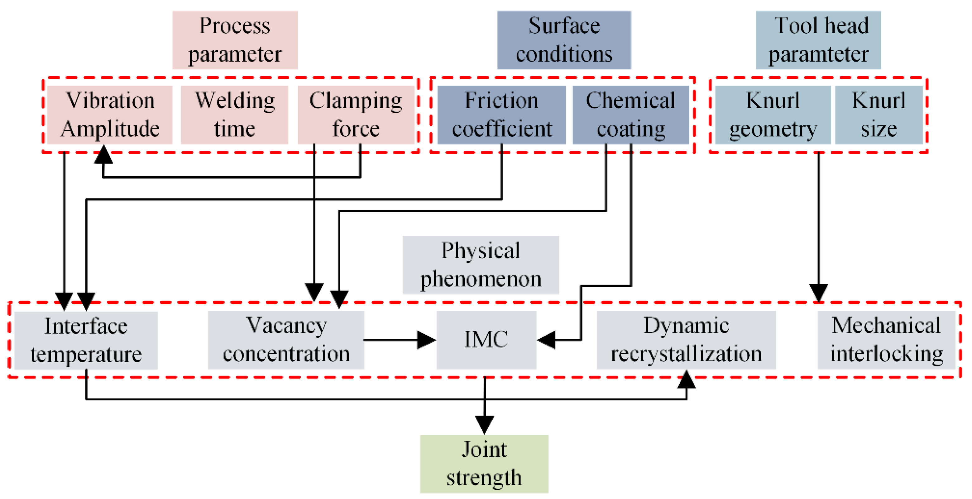
Figure 4.
(a) Schematic diagram of the USW [30]; (b) The wedge-reed welder; (c) The lateral drive welder.
Figure 4.
(a) Schematic diagram of the USW [30]; (b) The wedge-reed welder; (c) The lateral drive welder.
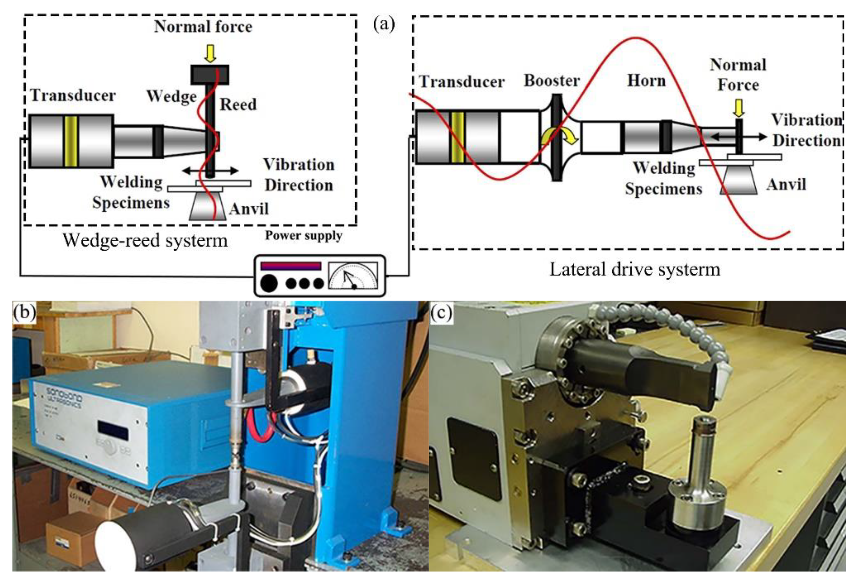
Figure 5.
Schematic diagram of the thermocouples for temperature measurement [32].
Figure 5.
Schematic diagram of the thermocouples for temperature measurement [32].
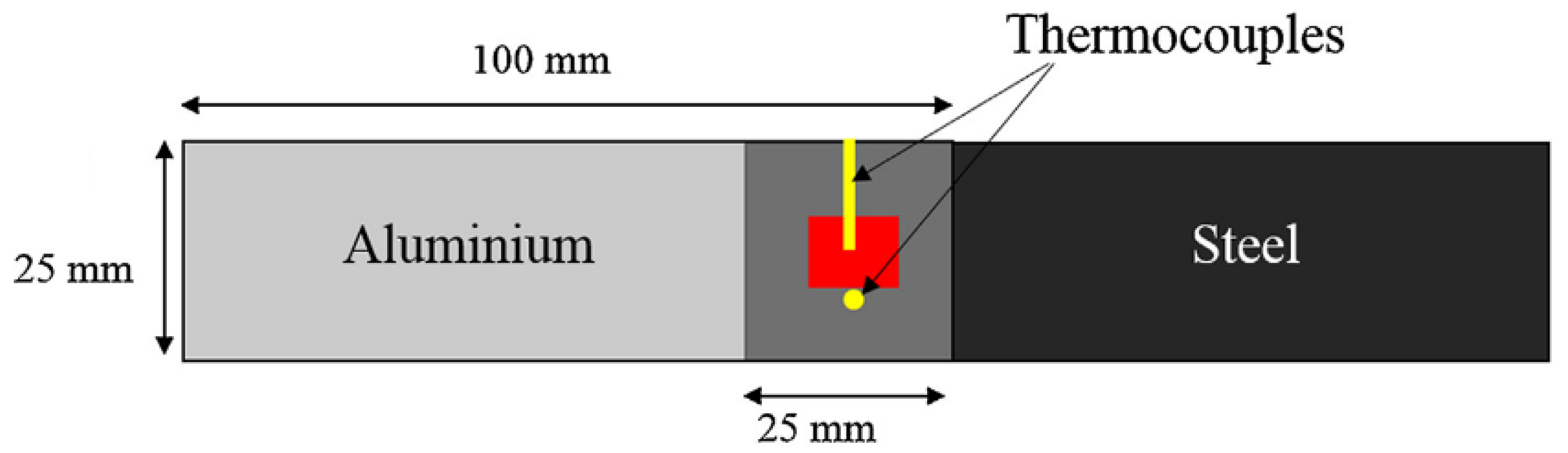
Figure 6.
Interface temperatures in 6111 aluminum alloy to DC04 steel from the weld center under the welding pressure of 1.4 kN [32].
Figure 6.
Interface temperatures in 6111 aluminum alloy to DC04 steel from the weld center under the welding pressure of 1.4 kN [32].
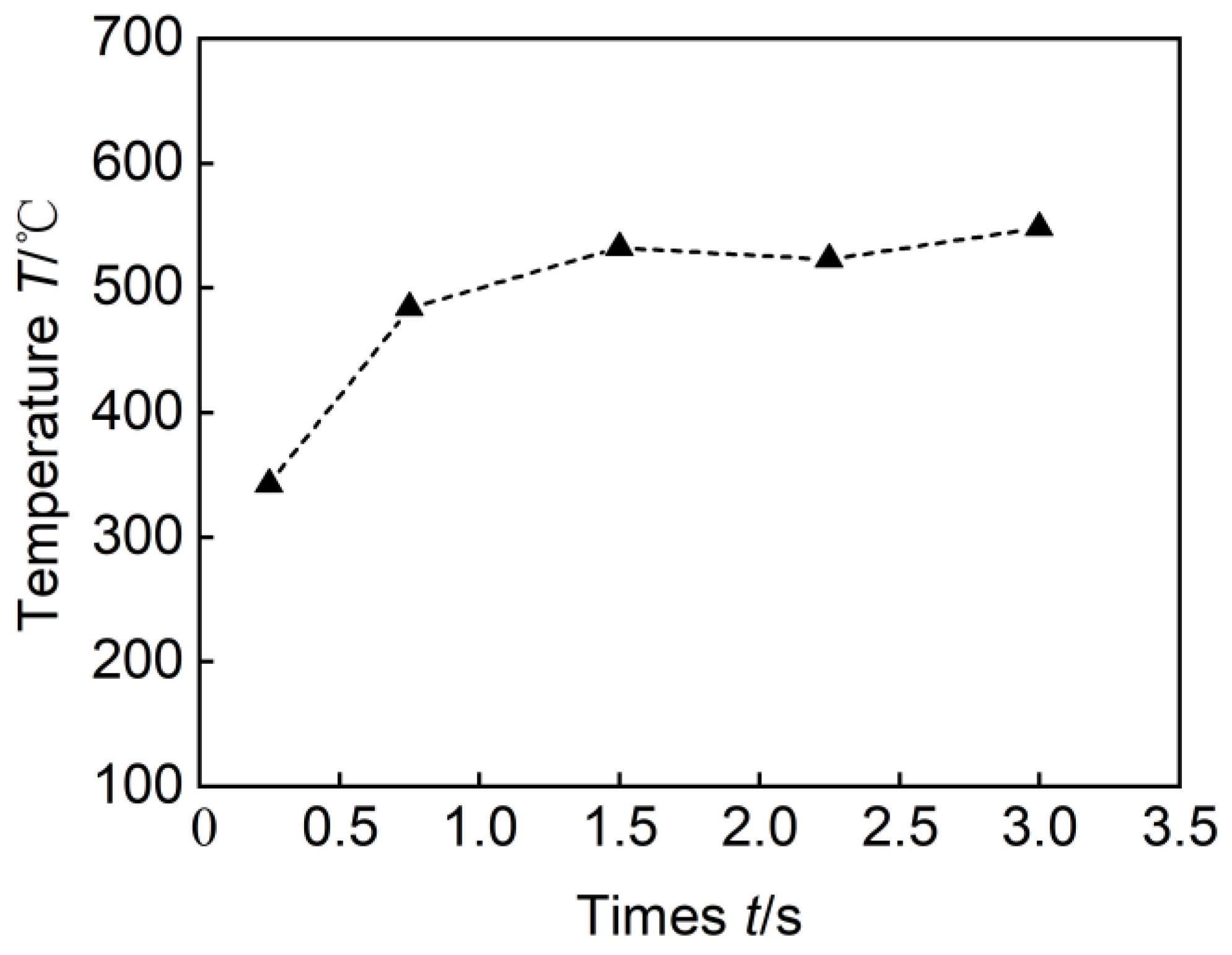
Figure 7.
Temperature field according to thermal imaging at the welding time of 1.5 s and 3.0 s [33].
Figure 7.
Temperature field according to thermal imaging at the welding time of 1.5 s and 3.0 s [33].
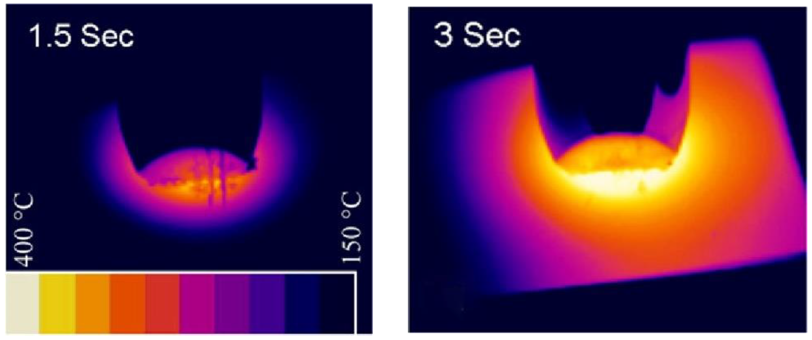
Figure 8.
Thermal cycles during USW with different vibration directions and welding time under 65 psi force [34].
Figure 8.
Thermal cycles during USW with different vibration directions and welding time under 65 psi force [34].
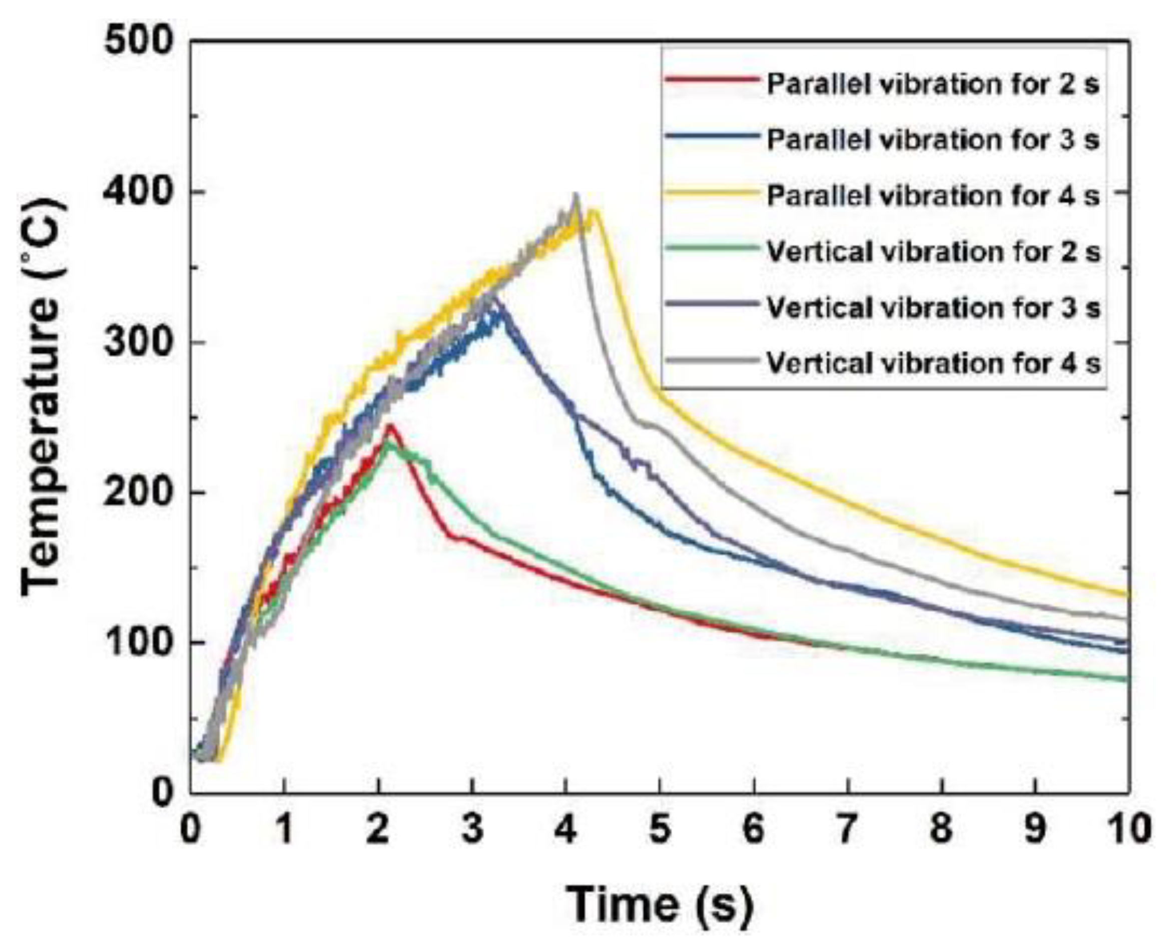
Figure 9.
Interface temperatures in 6111 aluminum alloy-to-DX56-Z and 6111 aluminum alloy-to-DX53-ZF from the weld center under the welding pressure of 1.4 kN [35].
Figure 9.
Interface temperatures in 6111 aluminum alloy-to-DX56-Z and 6111 aluminum alloy-to-DX53-ZF from the weld center under the welding pressure of 1.4 kN [35].

Figure 10.
Schematic diagram of temperature field of aluminum side surface in aluminum alloy and galvanized steel [32].
Figure 10.
Schematic diagram of temperature field of aluminum side surface in aluminum alloy and galvanized steel [32].
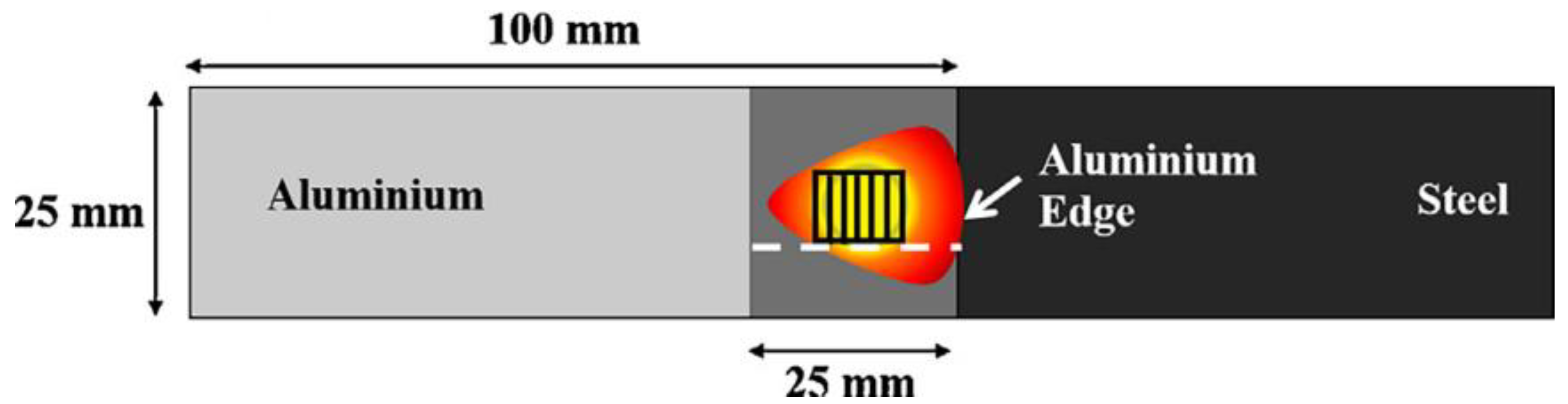
Figure 11.
3D presentation of sonotrode tip embedded Al with increasing welding times [32]: (a) 0.25 s; (b) 1.5 s; (c) 3.0 s.
Figure 11.
3D presentation of sonotrode tip embedded Al with increasing welding times [32]: (a) 0.25 s; (b) 1.5 s; (c) 3.0 s.
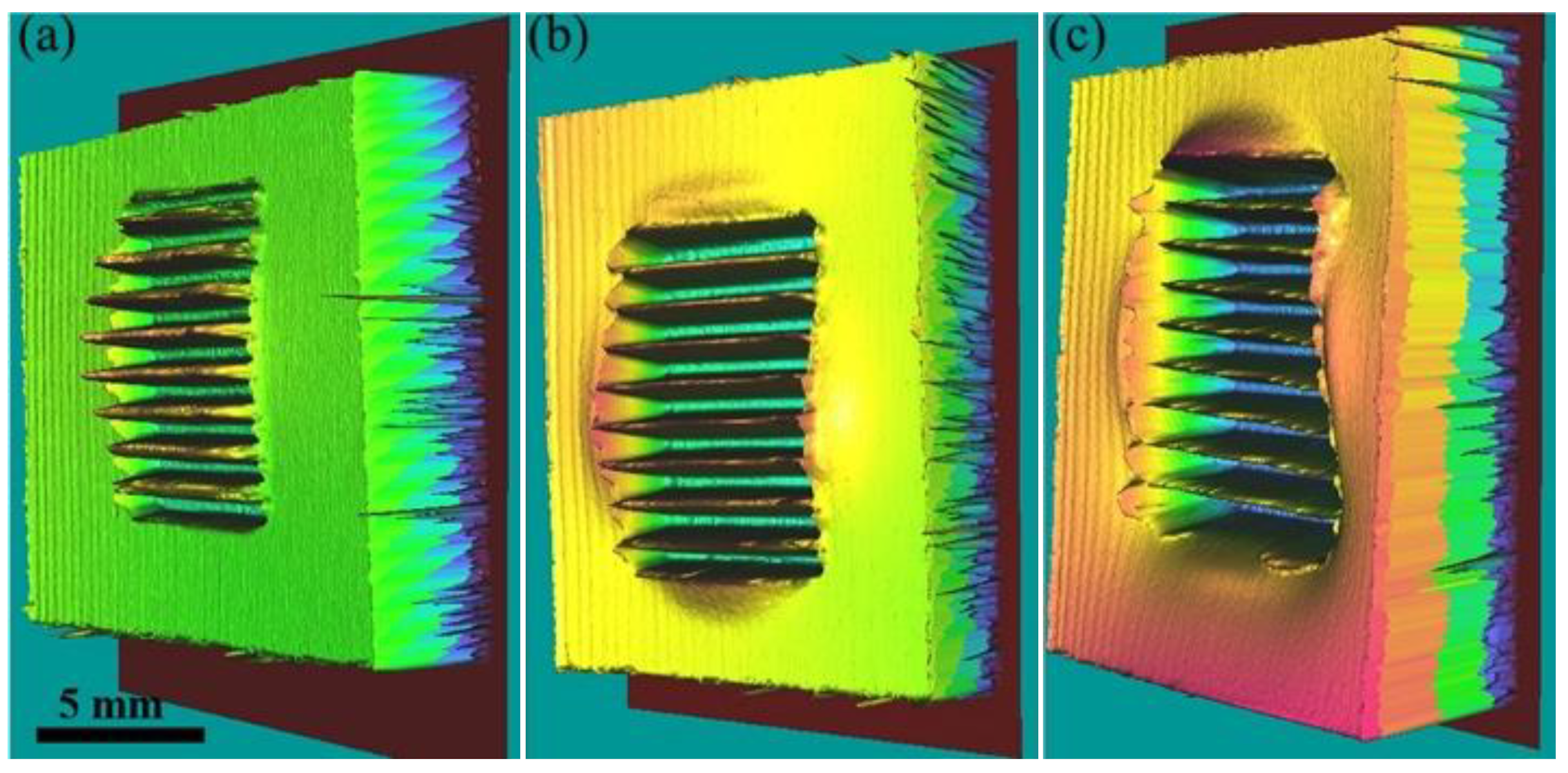
Figure 12.
Optical micrographs of weld cross-section with increasing welding energies [40]: (a) 75 J; (b) 125 J; (c) 200 J.
Figure 12.
Optical micrographs of weld cross-section with increasing welding energies [40]: (a) 75 J; (b) 125 J; (c) 200 J.
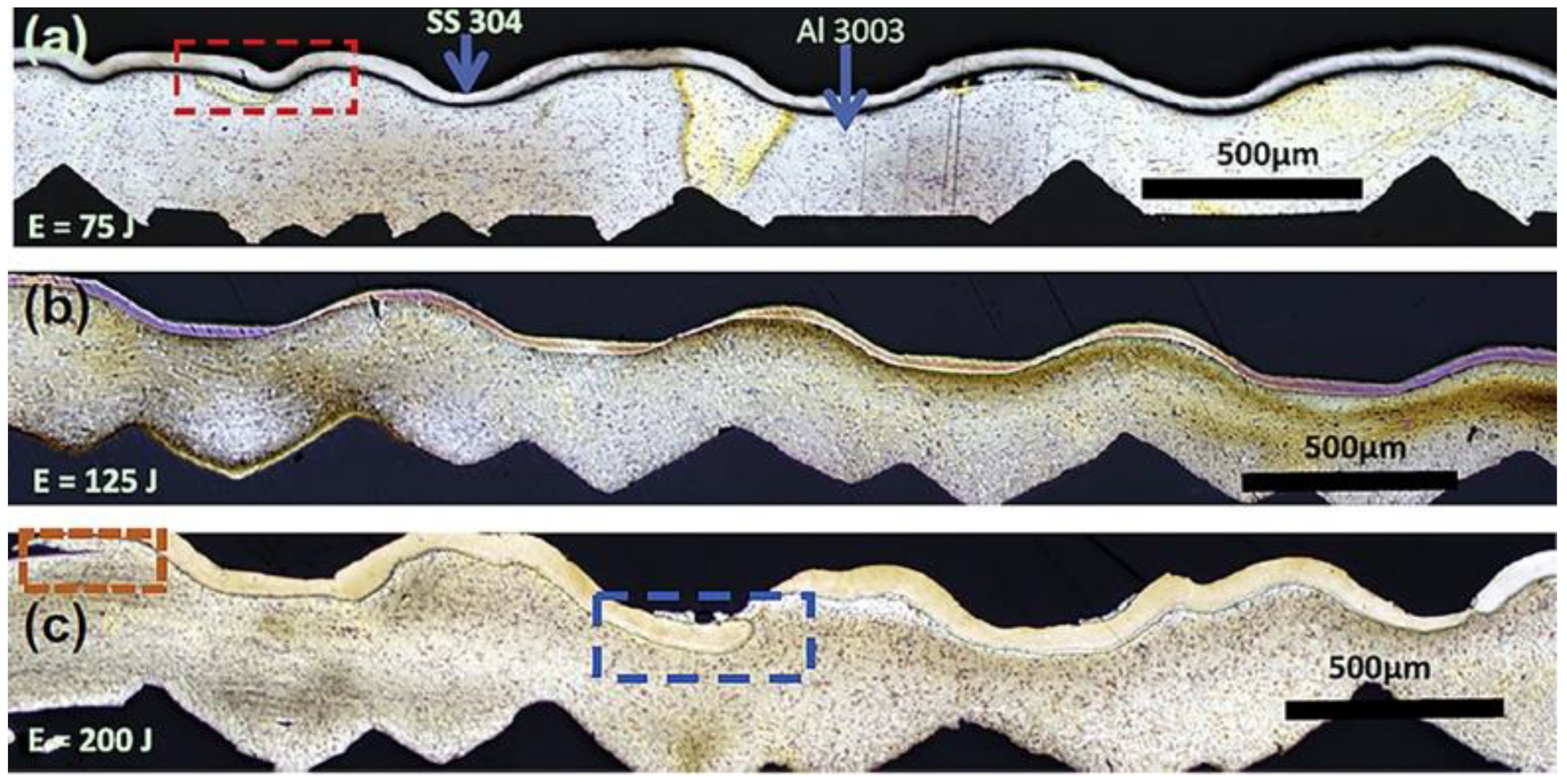
Figure 13.
Micromorphology of the welding interface [22]: (a) AA 3003-Al-alloy-to-AISI-304-SS joint with Cu interlayer; (b) AISI-304-SS-to-AA-3003-Al-alloy joint with Cu interlayer.
Figure 13.
Micromorphology of the welding interface [22]: (a) AA 3003-Al-alloy-to-AISI-304-SS joint with Cu interlayer; (b) AISI-304-SS-to-AA-3003-Al-alloy joint with Cu interlayer.

Figure 14.
(a) SEM images of the IMC reaction layers; (b) TEM images of the IMC reaction layers; (c) results from EDX composition line scans obtained by TEM across the IMC interface layers [44].
Figure 14.
(a) SEM images of the IMC reaction layers; (b) TEM images of the IMC reaction layers; (c) results from EDX composition line scans obtained by TEM across the IMC interface layers [44].
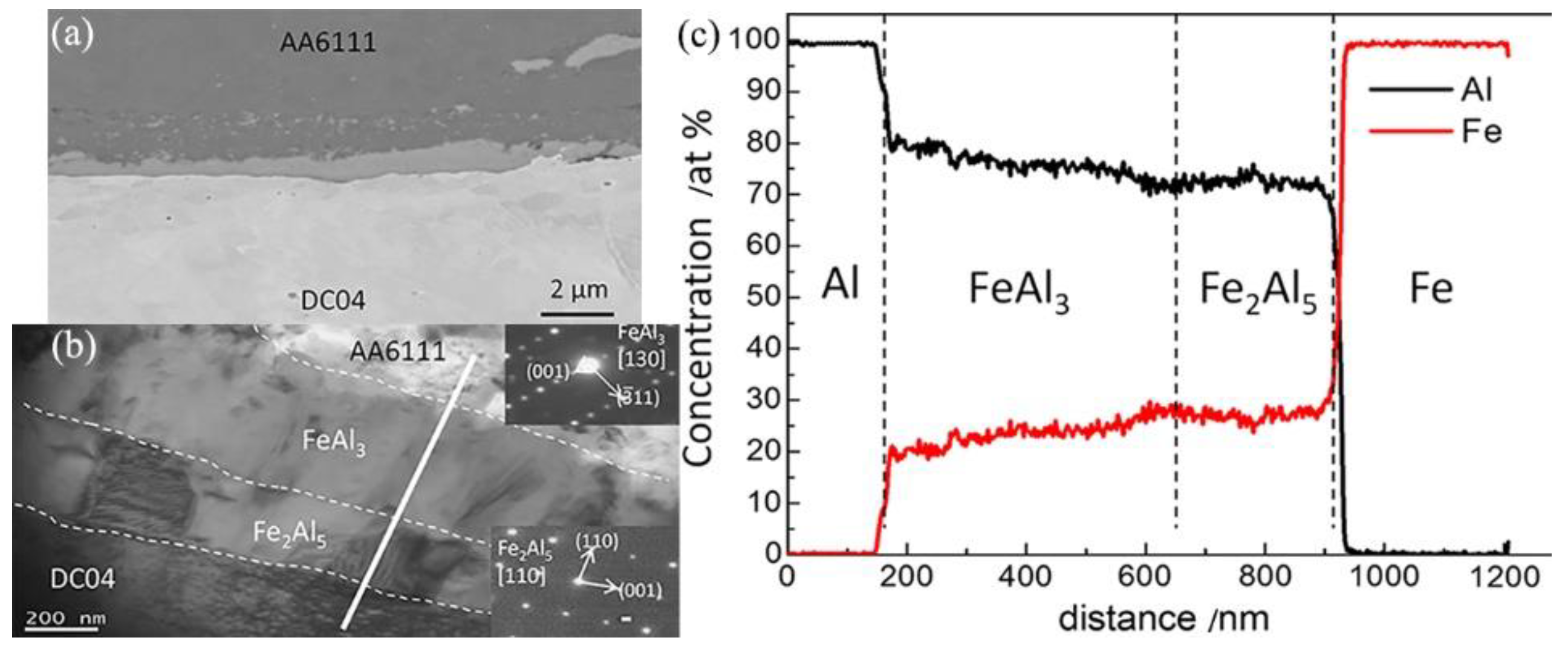
Figure 15.
EBSD results at the welding interface between 6111 aluminum alloy and DC04 steel [44]: (a) the dual-phase IMC reaction layer; (b) pole figures of Fe2Al5 phase; (c) pole figures of FeAl3 phase.
Figure 15.
EBSD results at the welding interface between 6111 aluminum alloy and DC04 steel [44]: (a) the dual-phase IMC reaction layer; (b) pole figures of Fe2Al5 phase; (c) pole figures of FeAl3 phase.
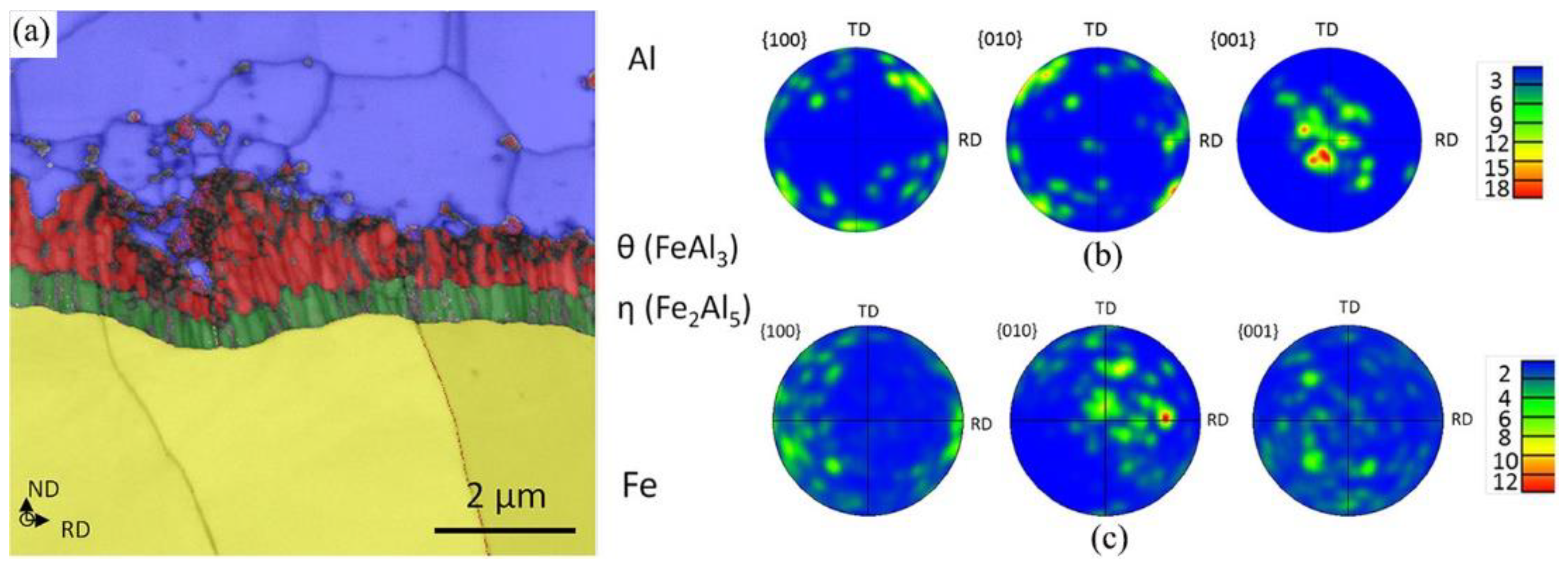
Figure 16.
EBSD results at the welding interface between 6061 aluminum alloy and 304 stainless steel [45]: (a) grain boundary character distribution map; {111} pole figures extracted from (b) bulk region B and (c) interface region.
Figure 16.
EBSD results at the welding interface between 6061 aluminum alloy and 304 stainless steel [45]: (a) grain boundary character distribution map; {111} pole figures extracted from (b) bulk region B and (c) interface region.
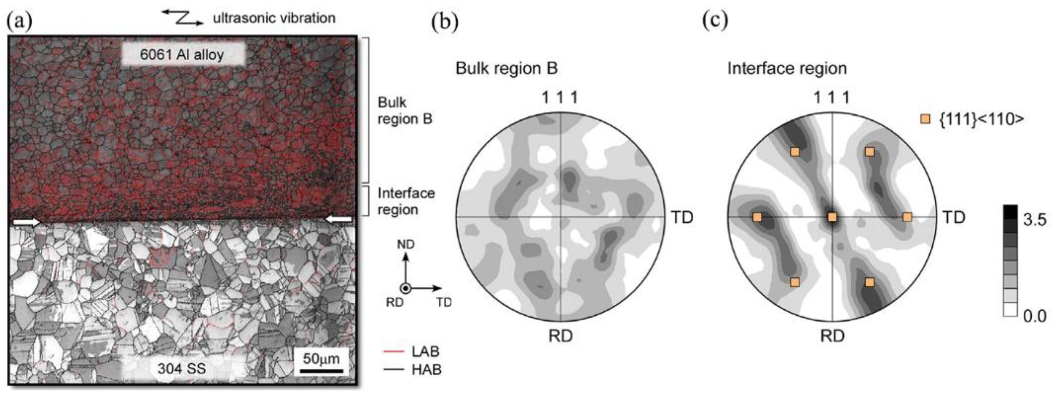
Figure 17.
Microstructure of welding interface between aluminum alloy and galvanized steel [38]: (a) SEM images of the IMC reaction layers; (b) Results from EDX composition line scans.
Figure 17.
Microstructure of welding interface between aluminum alloy and galvanized steel [38]: (a) SEM images of the IMC reaction layers; (b) Results from EDX composition line scans.
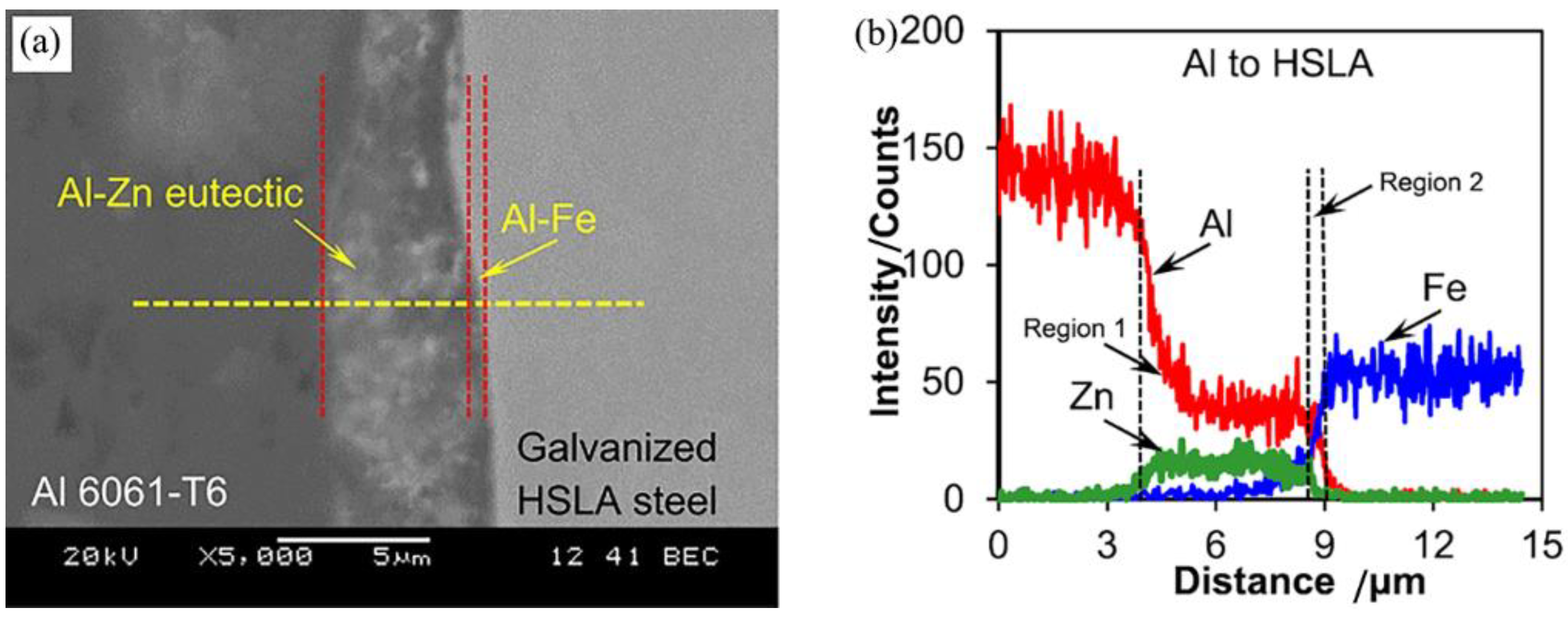
Figure 18.
High magnification microstructure images of Al-to-DX56-Z joints from the center of reaction layers at the interface of the steel sheet [3]: (a) 0.5 s; (b) 2.0 s; (c) 3.0 s.
Figure 18.
High magnification microstructure images of Al-to-DX56-Z joints from the center of reaction layers at the interface of the steel sheet [3]: (a) 0.5 s; (b) 2.0 s; (c) 3.0 s.
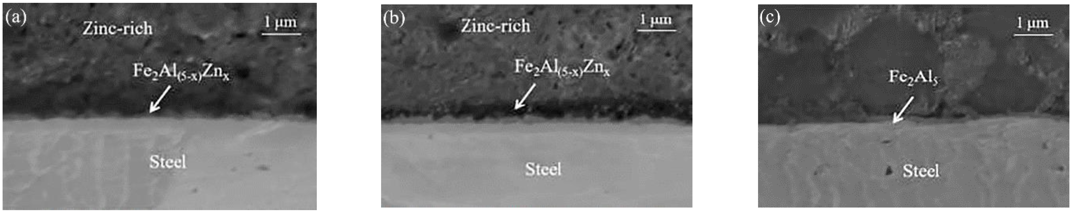
Figure 19.
CALPHAD predicted equilibrium phase fractions as a function of Fe [44]: (a) AA6111-to-DC04-steel; (b) AA7055-to-DC04-steel.
Figure 19.
CALPHAD predicted equilibrium phase fractions as a function of Fe [44]: (a) AA6111-to-DC04-steel; (b) AA7055-to-DC04-steel.

Figure 20.
High magnification EBSD Euler contrast maps from the weld interface with a different combination [35]: (a) Al-to-DC04; (b) Al-to-DX56-Z; (c) Al-to-DX53-ZF.
Figure 20.
High magnification EBSD Euler contrast maps from the weld interface with a different combination [35]: (a) Al-to-DC04; (b) Al-to-DX56-Z; (c) Al-to-DX53-ZF.

Figure 21.
The fracture surface of the aluminum side between aluminum alloy and DC04 steel with increasing welding times [32]: (a) 0.25 s; (b) 1.5 s; (c) 3.0 s.
Figure 21.
The fracture surface of the aluminum side between aluminum alloy and DC04 steel with increasing welding times [32]: (a) 0.25 s; (b) 1.5 s; (c) 3.0 s.
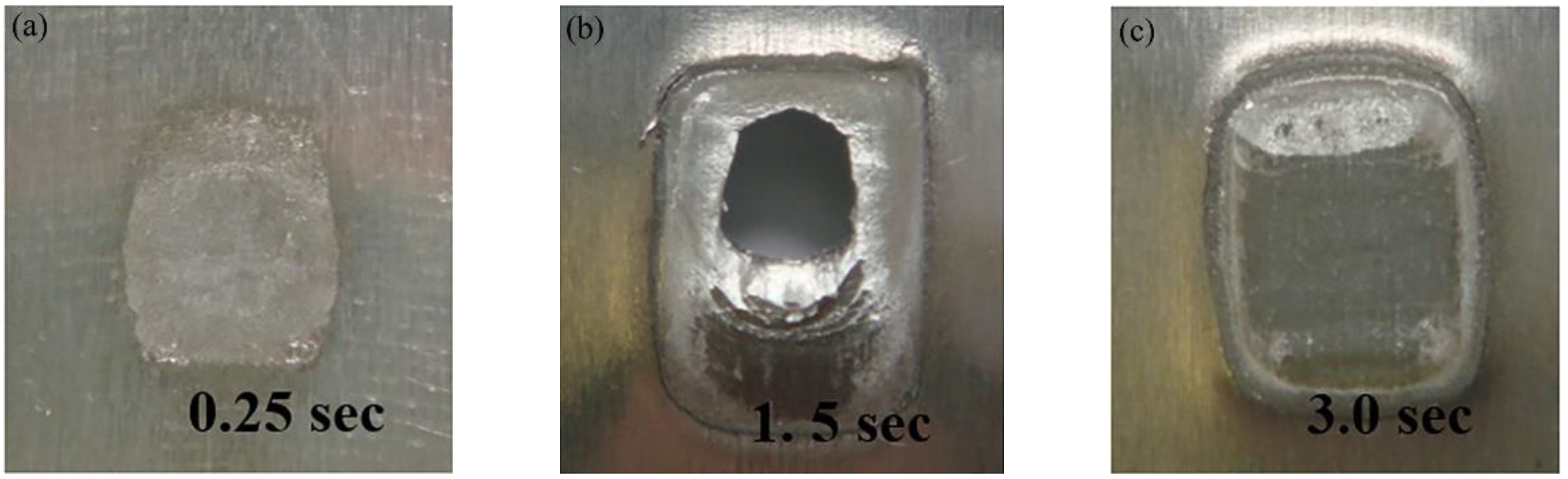
Figure 22.
Joint strength using C-tip and K-tip at 1.0 s welding time [49].
Figure 22.
Joint strength using C-tip and K-tip at 1.0 s welding time [49].
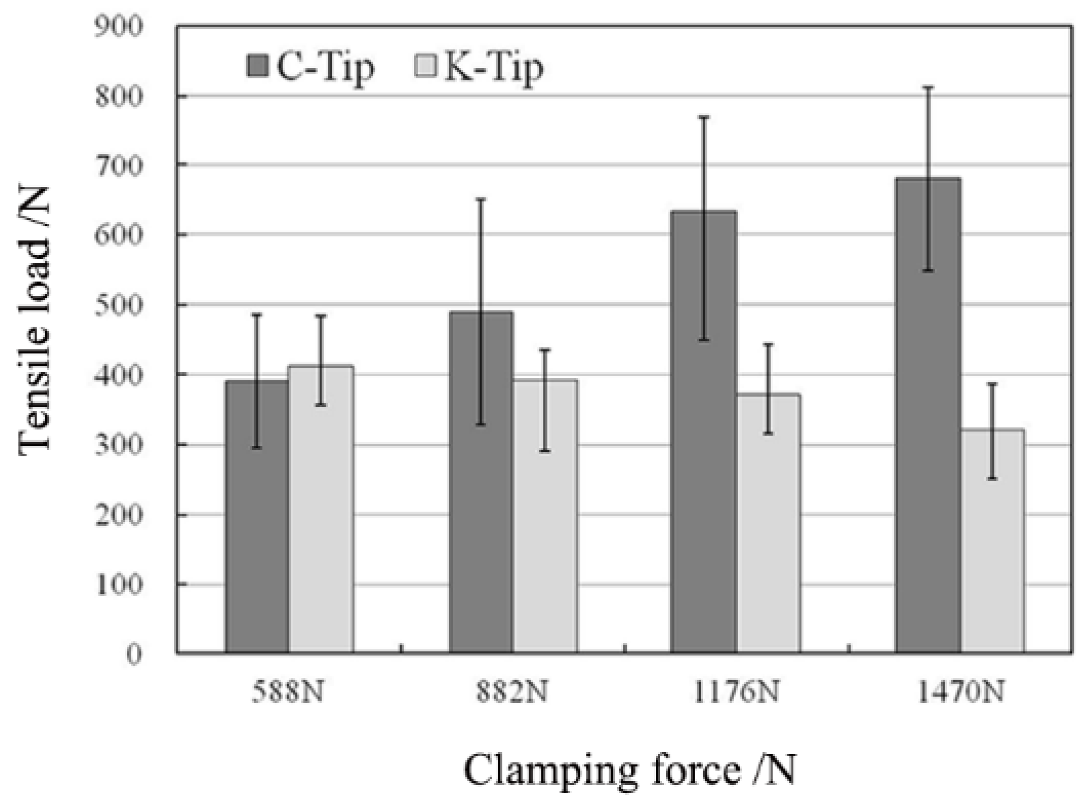
Figure 23.
Tensile failure locations of Al-6061-to-galvanized-HSLA-steel with an increase in the welding energy [38]: (a) 500 J; (b) 1000 J; (c) 1500 J; (d) 1750 J.
Figure 23.
Tensile failure locations of Al-6061-to-galvanized-HSLA-steel with an increase in the welding energy [38]: (a) 500 J; (b) 1000 J; (c) 1500 J; (d) 1750 J.

Figure 24.
Fracture path between Aluminum alloy and galvanized steel with an increase in the welding time [32]: (a) 0.5 s; (b) 3.0 s.
Figure 24.
Fracture path between Aluminum alloy and galvanized steel with an increase in the welding time [32]: (a) 0.5 s; (b) 3.0 s.
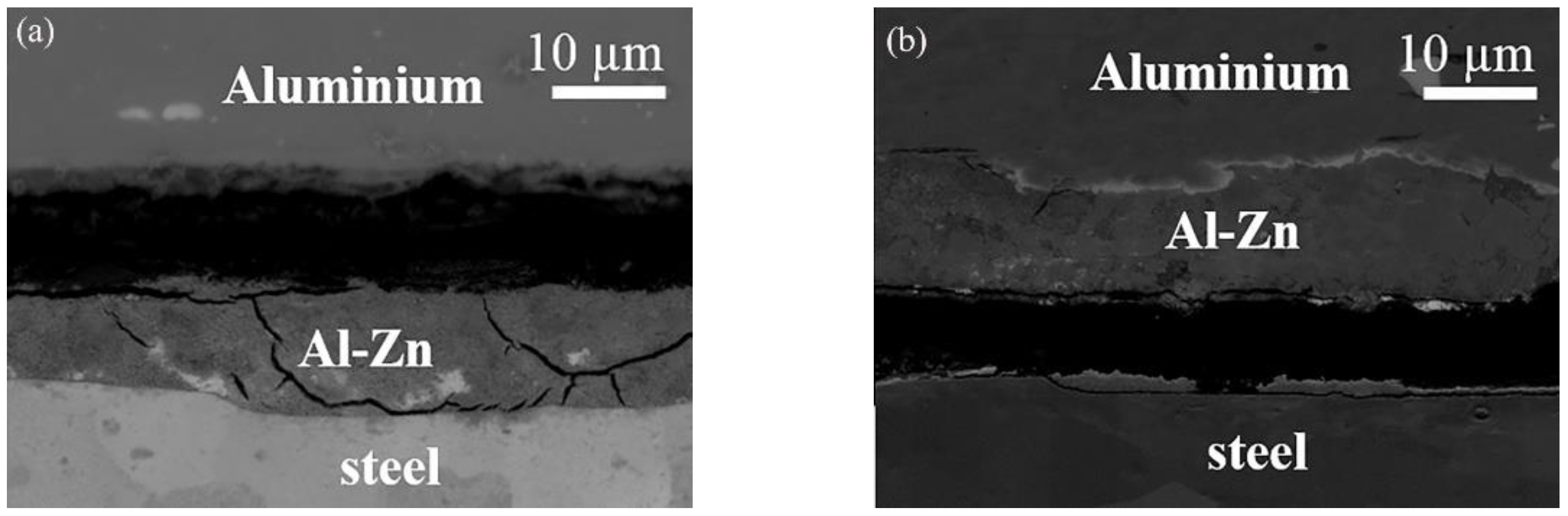
Figure 25.
(a) The effects of the insert metal and the thickness on the joint strength; (b) fracture morphology of joints with the insert metal [49].
Figure 25.
(a) The effects of the insert metal and the thickness on the joint strength; (b) fracture morphology of joints with the insert metal [49].

Figure 26.
Macroscopic images of the separated samples of USW Al/Mg/Al-clad-sheet-to-HSLA-steel joint [37]: (a) clad sheet side without Zn coating; (b) steel side without Zn coating; (c) clad sheet side with Zn coating; (d) steel side with Zn coating.
Figure 26.
Macroscopic images of the separated samples of USW Al/Mg/Al-clad-sheet-to-HSLA-steel joint [37]: (a) clad sheet side without Zn coating; (b) steel side without Zn coating; (c) clad sheet side with Zn coating; (d) steel side with Zn coating.

Figure 27.
S-N curves of the Al-to-HSLA-steel USW joints [5].
Figure 27.
S-N curves of the Al-to-HSLA-steel USW joints [5].

Figure 28.
3-D finite element model [51].
Figure 28.
3-D finite element model [51].

Figure 29.
Predicted temperature distributions at the weld plane of symmetry [51] after: (a) 0.5 s and (b) 1.0 s.
Figure 29.
Predicted temperature distributions at the weld plane of symmetry [51] after: (a) 0.5 s and (b) 1.0 s.
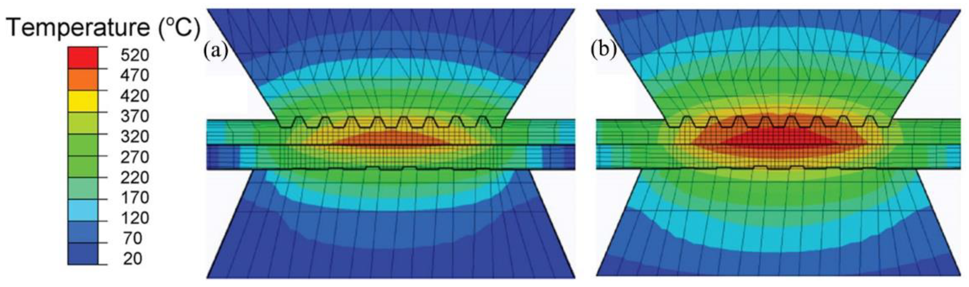
Figure 30.
Predicted Al deformation map at welding time of 1.0 s [52].
Figure 30.
Predicted Al deformation map at welding time of 1.0 s [52].

Figure 31.
Schematic diagram of perpendicular ultrasonic joining [53].
Figure 31.
Schematic diagram of perpendicular ultrasonic joining [53].

Figure 32.
Schematic diagram of multi-spot USW [46].
Figure 32.
Schematic diagram of multi-spot USW [46].

Table 1.
Welding strengths of USWed aluminum-to-steel joint.
| Base Metal | Welderpower | Welding Parameters | Weld Strength | Failure Mode | Ref. | ||||
|---|---|---|---|---|---|---|---|---|---|
| Energy | Time | Force | Amplitude | Evaluation | Max Value | ||||
| 1.0 mm–Al 6111-T4 and DX56-ZF Steel | 2.5 kW | - | 1.0 s | 1.4 kN | - | Tensile-shear | 2.7 kN | Interface failure | [3] |
| 1.0 mm–Al 6111-T4 to DX53-ZF Steel | 2.5 kW | - | 3.0 s | 2.3 kN | - | Tensile-shear | 3.1 kN | Interface failure | [3] |
| 1.25 mm–Al 6111-T4 and 1.2 mm–HLSA Steel | 2.5 kW | 2000 J | - | 0.4 MPa | - | Tensile-shear | 4.3 kN | TTT | [5] |
| 1.0 mm–IF Steel and Al 5052 | 3.5 kW | - | 2.5 s | 1.5 kN | 41 μm | Tensile-shear | 1.6 kN | - | [21] |
| 0.6 mm Al A3003 and 0.1 mm–AISI 304 Steel | 3 kW | - | 0.35 s | 0.3 MPa | 68 μm | Tensile-shear | 9.5 kN | Nugget pull-out | [22] |
| 1.0 mm–Al 6111-T4 and DC04 Steel | 2.5 kW | - | 1.5 s | 1.4 kN | - | Tensile-shear | 2.7 kN | Nugget pull-out | [31] |
| 1.0 mm Al 6022-T4 and 1.2 mm–DP600 Steel | 0.8 kW | - | 3.0 s | 0.448 MPa | - | Tensile-shear | 2.9 kN | Interface failure | [34] |
| 0.5 mm–Al 5754 O and 0.8 mm–HSLA Steel | 2 kW | 2000 J | - | 0.414 MPa | - | Tensile-shear | 3.7 kN | Interface failure | [36] |
| 1.5 mm–Al 6061-T6 and HSLA Steel | 2 kW | 1750 J | - | 0.4 MPa | - | Tensile-shear | 2.76 kN | TTT | [38] |
| 1.5 mm–Al 6061-T6 and ASTM Steel | 2 kW | 1500 J | - | 0.4 MPa | - | Tensile-shear | 3.36 kN | TTT | [38] |
| 300 μm–Al 3003 and 50 μm–304 Steel | 2.4 kW | 225 J | - | 0.207 MPa | 58 μm | U-tensile | 0.375 kN | - | [40] |
| 1.2 mm–Al A5052-H24 and 1.2 mm–Al A1050-H24 and 0.8 mm–SS400 Steel | 2.4 kW | - | 3.0 s | 588 N | 53 μm | U-tensile | 1.8 kN | - | [41] |
| 0.93 mm–Al 6111-T4 and 1 mm–DC04 Steel | 2.5 kW | - | 1.5 s | 1.4 kN | - | Tensile-shear | 2.8 kN | Nugget pull-out | [42] |
| 1.5 mm–Al 6061-T6 and AISI 304 Steel | 2 kW | 750 J | - | 0.4 MPa | - | Tensile-shear | 3.5 kN | TTT | [43] |
| 1.5 mm–Al 6061-T6 and ASTM A36 Steel | 2 kW | 1500 J | - | 0.4 MPa | - | Tensile-shear | 3.3 kN | TTT | [43] |
| 1.0 mm–Al A6111 and DC04 Steel | 2.5 kW | - | 1.5 s | 1.4 kN | - | Tensile-shear | 3.2 kN | Interface failure | [44] |
| 1.0 mm–Al A7055 and DC04 Steel | 2.5 kW | - | 1.5 s | 1.4 kN | - | Tensile-shear | 3.1 kN | Interface failure | [44] |
| 1.0 mm–Al 6061-T6 and 0.5 mm–304 Steel | 0.9–1.06 kW | 1200 J | - | 0.3 MPa | 51 μm | Tensile-shear | 2.8 kN | Nugget pull-out | [45] |
| 0.9 mm–Al A6005A-T4 and 1.0 mm–HCT980X Steel | 4 kW | 2000 J | - | 1.485 kN | 22.5 μm | Tensile-shear | 4.353 kN | Interface failure | [46] |
| 1.0 mm–Al 6061-T6 and 1.5 mm–A36 Steel | 2.5 kW | - | 1.8 s | 0.35 MPa | 30 μm | Tensile-shear | 3.91 kN | Mixed failure | [48] |
| 1.2 mm–Al A5052-H24 and 0.5 mm–Al A1050 and 0.8 mm–SS400 Steel | 2.4 kW | - | 3.0 s | 0.588 kN | - | Tensile-shear | 1.15 kN | - | [49] |
| 0.7 mm–Al A1100 and 0.2 mm–AISI 304 Steel | 3 kW | - | 0.72 s | 0.32 MPa | 68 μm | T-peel | 217.1 N | Interface failure | [50] |
Disclaimer/Publisher’s Note: The statements, opinions and data contained in all publications are solely those of the individual author(s) and contributor(s) and not of MDPI and/or the editor(s). MDPI and/or the editor(s) disclaim responsibility for any injury to people or property resulting from any ideas, methods, instructions or products referred to in the content. |
© 2022 by the authors. Licensee MDPI, Basel, Switzerland. This article is an open access article distributed under the terms and conditions of the Creative Commons Attribution (CC BY) license (https://creativecommons.org/licenses/by/4.0/).
Share and Cite
MDPI and ACS Style
Zhang, C.; Li, H.; Liu, Q.; Huang, C.; Zhou, K. Ultrasonic Welding of Aluminum to Steel: A Review. Metals 2023, 13, 29. https://doi.org/10.3390/met13010029
AMA Style
Zhang C, Li H, Liu Q, Huang C, Zhou K. Ultrasonic Welding of Aluminum to Steel: A Review. Metals. 2023; 13(1):29. https://doi.org/10.3390/met13010029
Chicago/Turabian StyleZhang, Changxin, Huan Li, Qianxi Liu, Chaowang Huang, and Kang Zhou. 2023. "Ultrasonic Welding of Aluminum to Steel: A Review" Metals 13, no. 1: 29. https://doi.org/10.3390/met13010029
Note that from the first issue of 2016, this journal uses article numbers instead of page numbers. See further details here.