Article

Microstructure and Mechanical Properties of Arc Zone and Laser Zone of TC4 Titanium Alloy Laser–TIG Hybrid Welded Joint

1
School of Aeronautical Materials Engineering, Xi’an Aeronautical Polytechnic Institute, Xi’an 710089, China
2
State Key Laboratory of Advanced Processing and Recycling of Non-Ferrous Metal, Lanzhou University of Technology, Lanzhou 730050, China
*
Authors to whom correspondence should be addressed.
Metals 2022, 12(11), 1854; https://doi.org/10.3390/met12111854
Submission received: 15 October 2022 / Revised: 25 October 2022 / Accepted: 26 October 2022 / Published: 30 October 2022

Abstract

:
As a high-efficiency and high-quality welding technology, laser-tungsten inert gas (laser–TIG) hybrid welding has been widely used in the aerospace and marine equipment industries. Through laser–TIG hybrid welding of TC4 titanium alloy, the effect of the current on the weld formation, the microstructure and mechanical properties of the arc zone, and the laser zone was studied. The results show that the molten pool in the arc zone will flow periodically, and the flow becomes more intense with an increase in the current, which will result in a finer grain size in the arc zone than in the laser zone, having the effect of eliminating pores. The spacing of the α′ martensite beams in the laser zone is narrower, with an average spacing of 0.41 μm. The β phase increases gradually with the increase in the current, which will lead to a downward trend in the average hardness of both zones. The average hardness value of the laser zone, containing more α′ martensite and less β phase, is slightly higher than that of the arc zone. The hardness uniformity of the laser zone is also significantly better than that of the arc zone. The tensile strength of the joint shows a trend of increasing first and then decreasing, and the joint with I = 50 A presented the highest tensile strength of 957.3 MPa, approaching 100% of the base metal, and fractured in the fusion zone.

1. Introduction

TC4 titanium alloy is a typical α+β two-phase titanium alloy. Due to its low density, high specific strength, excellent corrosion resistance, and fatigue resistance, it has been widely used in the aerospace and marine equipment industries [1,2]. Just as the pressure hull of China’s Jiaolong and Endeavour deep-sea manned submersible is made of TC4 titanium alloy [3,4]. The joining methods of titanium alloy are mainly focused on TIG, metal inert gas welding (MIG), laser welding, and electron beam welding. However, there are many problems when welding with these methods [5,6]. During arc welding, the welding speed is slow, the arc heat source is not concentrated, the heat input of the joint is large, the grains are easily coarsened, and the welding deformation is large. High-energy beam welding such as laser welding has a high energy density, a large penetration depth, and a small welding heat-affected zone but requires an extremely high welding clamping accuracy, so it is not suitable for welding large and thick plates [7,8].
As a high-efficiency and high-quality welding technology, laser–arc hybrid welding has become a widely used welding technology [9,10,11]. Compared with a single heat source, the laser–arc hybrid heat source can effectively control the appearance of the weld seam. Frostevarg et al. [12] pointed out that reducing the temperature gradient and welding speed can prevent the formation of weld concave. The laser can attract and compress the arc, improving the energy density of the arc. There is a coupling effect between the laser and the arc during the welding process, which realizes welding with wider gaps and thicker plates [13,14]. However, due to the completely different characteristics of the laser and arc heat sources, the welds of laser–arc hybrid welding are divided into an arc zone and a laser zone [15,16]. The arc zone and the laser zone are very different in macroscopic morphology and microstructure [17].
Liu et al. [18] found that in the laser–arc hybrid welding process, the arc zone and the laser zone have completely different thermal cycles, resulting in a very complex weld microstructure in the two zones. Fang et al. [19] carried out laser welding of Ti-6Al-4V titanium alloy and found that the weld seam microstructure has obvious grain growth and a large amount of acicular α′ martensite. At the same time, the hardness of the weld increases with an increase in the cooling rate. Fu et al. [20] conducted a study on underwater laser welding of titanium alloy and showed that the α′ martensitic sheet becomes thinner due to a higher cooling rate. Long et al. [21] conducted laser welding on TC4 titanium alloy; the results show that a large amount of point-like β phase in the weld will reduce its hardness, and the fatigue strength of laser welded joints is lower than that of vacuum electron beam welded joints. Therefore, under different welding heat sources and cooling conditions, titanium alloys will cause differences in the composition of precipitates, grain size, and microscopic morphology, which affect the mechanical properties of welded joints.
Frostevarg et al. found that adjusting the laser–arc distance can control the position of the keyhole in the molten pool, thereby changing the flow of the molten pool and effectively preventing the occurrence of undercut [22]. Gao et al. [23] through laser–arc composite welding experiment, found that the size difference between the arc zone and the laser zone can be reduced by increasing the arc current and groove cross-sectional area. A high current can speed up the flow of molten metal to the root of the molten pool, and increasing the groove area can reduce the resistance of metal flow. The laser–arc energy ratio also has a great influence on the microstructure of the weld, so a hybrid weld with a lower laser–arc energy ratio has better mechanical properties. Wei et al. studied the effect of Marangoni convection on molten pool flow during laser–arc hybrid welding, finding that laser–dual gas metal arc (GMA) hybrid welding is beneficial to the distribution of alloy elements and the homogenization of weld microstructure [24].
Mahrle et al. [25] and Rai et al. [26] conducted a numerical simulation study on the molten pool flow during laser welding, finding that the main factor in the molten pool flow was Marangoni convection. Zhao et al. [27] observed the metal flow on the surface and inside of the molten pool in CO2 laser–arc hybrid welding, finding that the molten pool metal flows to the inside of the keyhole and improves the uniformity of the weld metal. Liu et al. [28] performed laser–MIG hybrid welding on 316 stainless steel, finding that the alternating magnetic field can improve the penetration ability of the composite heat source by promoting the laser-induced plasma. Therefore, by adjusting the laser–arc distance or the laser–arc energy ratio or by increasing the external magnetic field, the flow of the molten pool metal can be improved and the penetration ability of the heat source can be increased. Wang et al. [29] conducted laser–TIG hybrid welding on 6061-T6, and the results showed that the microstructure of the fusion zone and heat effect zone was changed by the hybrid welding source.
Most of the above research focuses on changing the flow of the molten pool to increase the penetration depth and improve the weld formation. There are few studies on the inhomogeneity of the arc zone and the laser zone caused by laser–arc hybrid welding, especially the phase composition and grain evolution process of the arc zone and the laser zone. However, in the laser–arc hybrid welding process of TC4 titanium alloy, there are great differences in the phase composition, grain size, and microscopic morphology between the arc zone and the laser zone, which will affect the mechanical properties of the welded joints. Therefore, it is of great significance to study the phase composition and grain evolution process of the arc region and the laser region. In this paper, laser–TIG hybrid welding of TC4 titanium alloy is carried out. Through experimental research and theoretical analysis, the effects of different currents on the weld formation, microstructure, and mechanical properties of the arc zone and laser zone are studied. The evolution process is analyzed to provide a reliable theoretical basis for the application of TC4 titanium alloy.

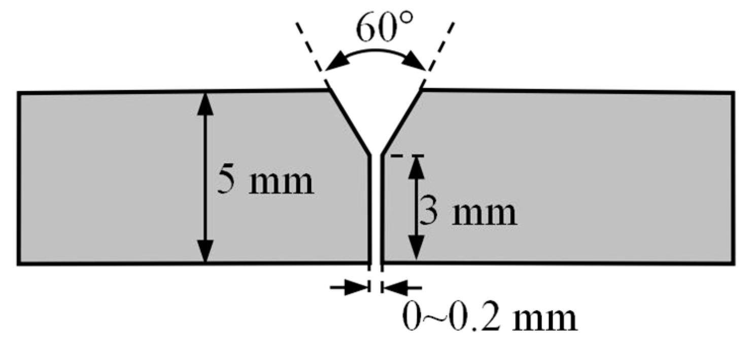
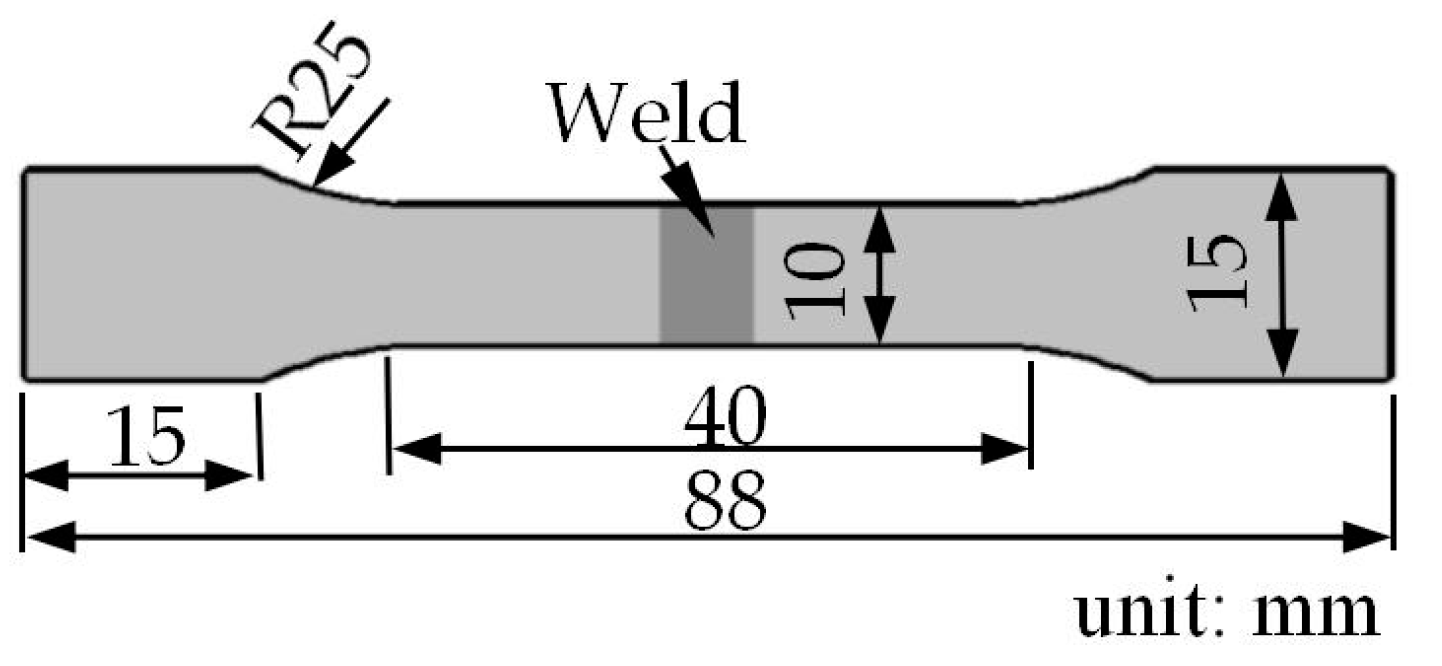
2. Experimental Processes

In this study, the TC4 titanium alloy was used as base metal and welding wire. The base metal is supplied in the rolled and annealed state with the dimensions of 100 mm × 50 mm × 5 mm. The welding wire diameter is 1.2 mm. The chemical composition of base metal and welding wire are shown in Table 1.
The test adopts flat butt welding. As shown in Figure 1, according to the requirements of the laser–TIG hybrid welding process, the groove of the TC4 titanium alloy test plate is designed as a Y-shaped groove, the groove angle is 60°, the blunt edge is 3 mm thick, and there is a butt gap of 0–0.2 mm. Wipe the base metal surface with acetone before welding to ensure that the surface is clean and free of stains.
Figure 2a shows the laser–TIG hybrid welding system composed of HS-CM-3000-C-G2 fiber laser system (CF2110177CM30CG2, Han’s Photonics, Shenzhen, China), AOTAI-WSME-280i multifunctional TIG welding machine (Aotaidianqi, Jinan, China), and WF-007A multifunctional automatic wire feeder (Handa, Jinan, China). When the sample is welded, the welding wire is in front, the laser is in the middle, and the TIG arc is behind. The angle α between the tungsten electrode and the workpiece surface is 45°, the angle β between the laser axis and the vertical line is 15°, and the angle γ between the welding wire and the workpiece surface is 30° [28,30]. The distance between the top of the tungsten electrode and the workpiece surface (DA) is 3–4 mm, the distance between the top of the tungsten electrode and the laser beam (DL-A) is 2 mm, and the laser defocus amount (Δf) is 2 mm, as shown in Figure 2b.
In the welding process of the laser–TIG hybrid, the laser power P is 1.5 kW, the TIG welding current I is 30–50 A, the welding speed ν is 20 cm/min, and the wire feeding speed is 150 cm/min. The specific experimental parameters are shown in Table 2. In order to prevent the titanium from absorbing O, H, and N during the welding process, argon gas with a purity of 99.99% was used to protect the front and back sides, and the flow rates were 15 L/min and 5 L/min, respectively. As shown in Figure 3, the K-type nickel-chromium-nickel-silicon thermocouple was used to collect the temperature during the welding process, and the collection point was 10 mm from the center of the weld. The image acquisition of the laser–arc morphology of the welding process was carried out by a CP-80 high-speed camera.
The test samples were obtained from the joints by the wire-cutting method. The surfaces of metallographic specimens with a size of 25 mm × 5 mm × 5 mm were ground and polished, etched in 1 mL of HF, 3 mL of HNO3, and 46 mL of H2O solution, and then observed on an LSM800 optical metallographic microscope (ZEISS, Guangzhou, China). The microstructure and elements distribution of the welded joint were examined by thermal field-emission scanning electron microscope (SEM) and energy dispersive spectroscopy (EDS).
An HVS-1000 (BUEHLER, Shanghai, China) microhardness tester was used to measure the Vickers hardness of the weld seam, fusion zone, heat-affected zone, and base metal with 1000 g load and 10 s residence time. A butt joint tensile test was used, and the specimen was machined to ensure that the weld seam was centered on the specimen. Figure 4 shows the shape and dimensions of the tensile test specimens. Tensile tests were performed by electronic tensile testing machine at room temperature with a loading rate of 3 mm/min. Three tensile samples for each parameter were tested and averaged.

3. Results and Analysis

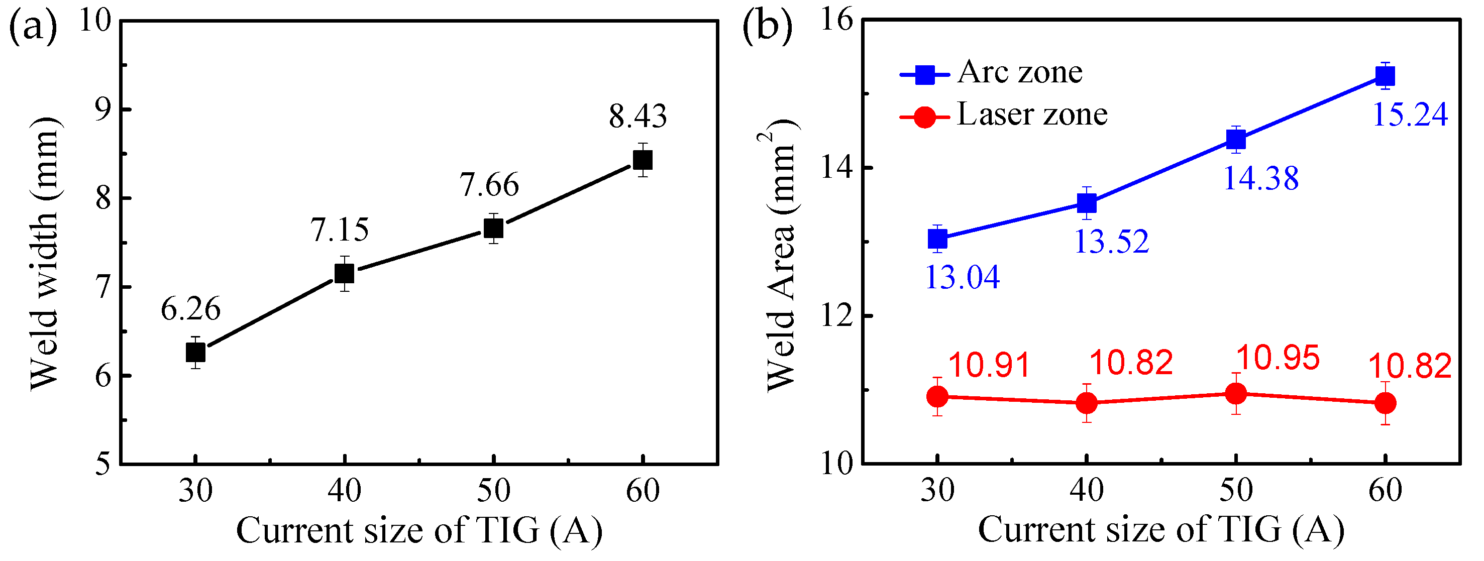
3.1. Effect of Current Size on Welding Formation

Figure 5 shows the surface morphology of laser–TIG hybrid welded joints with different current. It can be seen that continuous and complete welded joints can be formed under different currents. No obvious defects such as a lack of fusion, undercut, and pores were found on the surface of the weld. However, pits were found to appear in the center of the weld surface, as indicated in Figure 5.
The laser–TIG morphology, in a stable state with different currents, is shown in Figure 6. The results show that the shape of the laser–arc, the melting of the welding wire, and the shape of the molten pool are basically in a stable state. Droplet transfer is a stable contact transfer during welding. When the current is 30 A, the arc shape is small, but, as the current increases, the arc gradually increases, and the width of the molten pool also increases gradually.
Figure 7 shows the laser–TIG morphology at 1ms intervals when the current is 50A. From Figure 7a,c, it can be found that the molten pool near the laser beam has bulges, and spatters are generated. From Figure 7b,d, it can be found that the molten pool near the laser beam is depressed. Therefore, in the process of laser–arc hybrid welding, the molten pool flows violently, periodic undulation appears near the laser beam, and the fluctuation period is 2 ms. This periodic undulation causes not only spatter but also pits on the weld surface after the molten pool has solidified. As shown in Figure 5, as the current increases, the pits become more and more obvious, indicating that the flow in the arc region is more intense.
Figure 8 shows the cross-sectional morphology of the laser–TIG hybrid welded joints with different currents. As shown in Figure 8a, the cross-sectional morphology at the current of 30 A is a typical "nail" shape, and pores appear near the fusion zone. Due to the characteristics of the laser–TIG hybrid welding heat source, the wider zone at the upper part of the joint is called the arc zone, and the narrower zone at the lower part is called the laser zone [31]. As the current increases, the arc zone gradually increases, while the laser zone is basically unchanged, and the "nail" shape of the weld of the joint cross-section also gradually changes to a "cup" shape. At the same time, as the current increases, the pores in the arc region gradually decrease. When I = 50 A and I = 60 A, the pores mainly appear in the laser zone, which is related to the periodic violent flow of the molten pool in the arc zone. The pores in the laser zone decrease with increasing current, but increase again when I = 60 A. This is because when the current is larger, the molten pool stays at a high temperature for a longer time, which will dissolve more gas, resulting in an increase in pores.
Figure 9 shows the width and cross-sectional area of the welded joint with different welding currents. It can be seen from Figure 9a that the weld seam width increases from 6.23 mm to 8.43 mm with an increase in the welding current. As can be seen from Figure 9b, as the current increases, the cross-sectional area of the arc region increases from 13.04 ± 0.19 mm2 to 15.24 ± 0.18 mm2. The area of the laser zone weld seam is basically unchanged, which is 10.91 ± 0.26 mm2, 10.82 ± 0.16 mm2, 10.95 ± 0.28 mm2, and 10.82 ± 0.29 mm2, respectively. Therefore, it can be concluded that the weld width and the area of the arc zone gradually increase with an increase in the current, while the magnitude of the current has no obvious effect on the area of the laser zone.

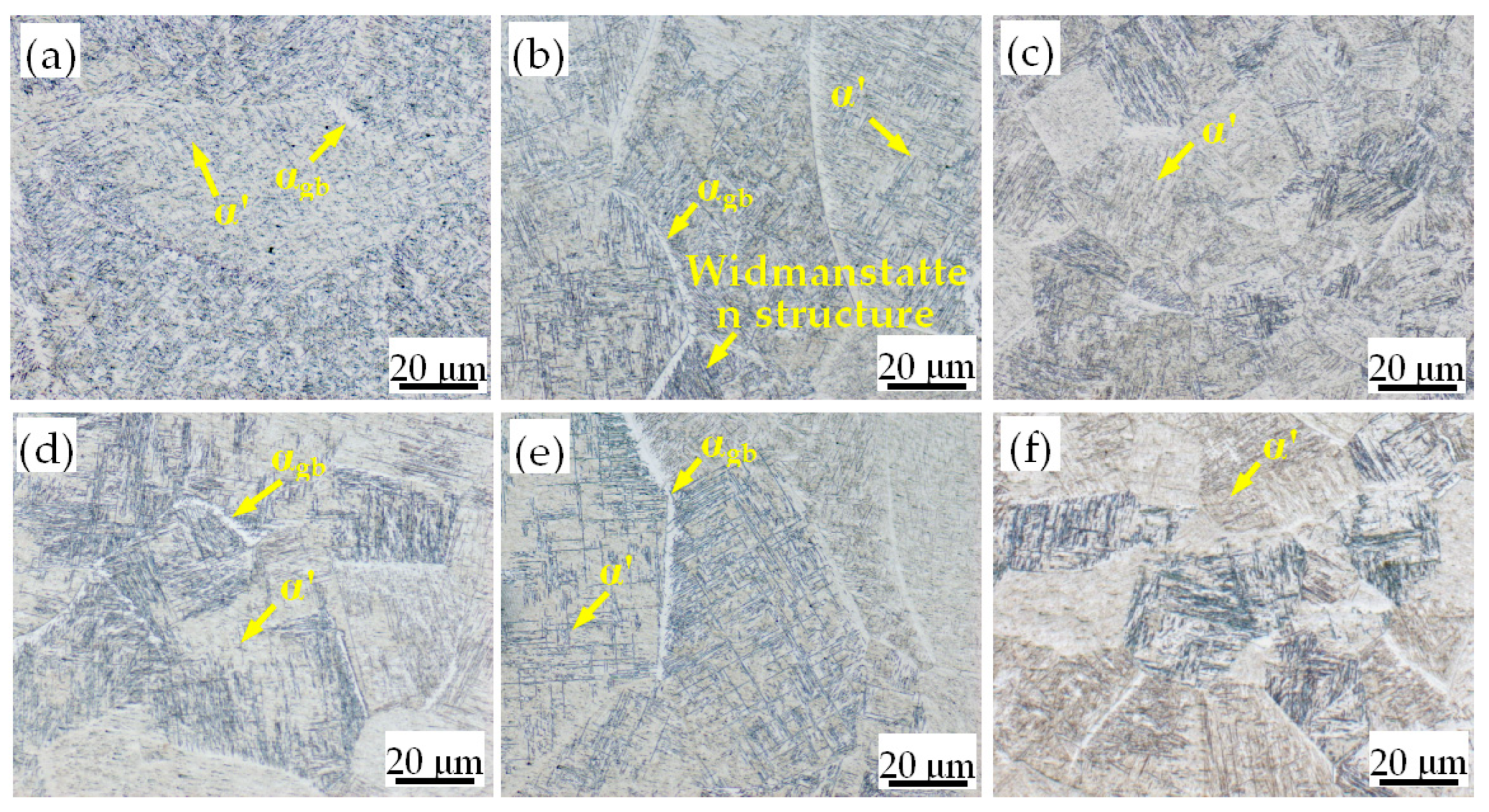
3.2. Effect of Current Size on Microstructure

Figure 10 shows the microstructure of the laser–TIG hybrid welded joints under different currents. The weld zone of TC4 titanium alloy is composed of a large number of columnar crystals and a small amount of equiaxed crystals, and there are differences in the size of the columnar crystals in the arc zone and the laser zone. As shown in Figure 10a,b,d,e, the size of the columnar crystals in the arc zone at the upper part of the weld is smaller, while the size of the columnar crystals in the laser zone at the lower part of the weld is comparatively larger. The grain size of the joint heat-affected zone is smaller than that of the weld seam, as shown in Figure 10c,f.
The microstructure of the weld zone of TC4 titanium alloy is composed of relatively coarse β grains; the β grain boundaries are complete and clear, and a large number of slender acicular α′ martensite is intertwined in the grain. At the grain boundary, a clear and continuous grain boundary αgb phase is found, and Widmanstatten structure is also found on both sides of the αgb. The microstructure of the heat-affected zone of the welded joint is mainly composed of acicular α′ martensite intertwined with the basket structure and Widmanstätten structure.
During the laser–TIG hybrid welding process of TC4 titanium alloy, due to the concentration of laser beam energy, the β phase in the weld seam grows rapidly to form coarse columnar crystals. During subsequent cooling, the β phase does not have time to transform into the α phase, so it will directly shear into supersaturated α′ martensite, and a scattered and staggered microstructure will appear. The laser zone in the lower part of the molten pool has less heat accumulation than the arc zone in the upper part of the molten pool, so it will cool first, eventually forming coarse columnar crystals. The cooling rate in the upper arc zone is relatively slow, and the resulting coarse columnar crystals are broken under the intense flow of the molten pool under the combined action of laser–TIG. Therefore, the finally formed grains are smaller than the laser zone.
Figure 11 shows the microstructure of the arc zone with different currents. In order to clearly observe the grain size of TC4 titanium alloy in the arc zone of laser–TIG hybrid welding, the grain boundaries in the picture are marked with dotted lines. It can be seen that with the increase in the current, the grains in the arc zone gradually decrease first and then increase, reaching the minimum when I = 50 A. This is because, as the current increases, the arc zone in the upper part of the molten pool flows more intensely, and the effect of fragmentation is more significant, thus making the grains finer. However, when I = 60 A, the larger current leads to a longer residence time at high temperature in the arc zone, and the grains grow gradually after a longer period of high temperature.
Figure 12 shows the SEM morphology of the welded joint when I = 50 A. It can be seen that the microstructure of the welded joint is a plurality of mutually parallel α′ martensitic bundles mixed with a narrow residual β phase and then crisscrossed to form a basket structure. Figure 12a shows the arc zone, where the cooling rate is slow and the spacing between the α′ martensite bundles is larger, with an average spacing of 0.63 μm. Figure 12b shows the laser zone, where the cooling rate is fast and the α′ martensite beam spacing is small, with an average spacing of 0.41 μm, which is 65% of the arc zone.
By scanning the arc zone and the laser zone, the atomic percentages of the Al elements in the two zones under different currents are obtained, as shown in Figure 13. It was found that the content of Al in the arc zone and the laser zone did not change much with the increase in the current. However, the content of the Al element in the laser zone is higher than that in the arc zone, and the former is about 1.1 times that of the latter. The arc zone is closer to the laser–TIG, the molten pool stays at high temperature for a long time, and the Al with a low boiling point is easily evaporated, thereby reducing the content of the Al element. As a stable element of α-Ti, Al can effectively strengthen α-Ti. So, a denser α′ martensite bundle can be found in the laser region, as shown in Figure 12.

3.3. Mechanical Properties of Welded Joints

Figure 14 shows the microhardness distribution of vertical weld at currents I = 30 A and I = 50 A. It can be seen that with the increase in the distance from the surface of the weld, the microhardness value of the weld first fluctuates greatly and then tends to be stable. Figure 15 shows the average hardness values and standard deviation values of microhardness in the arc zone and laser zone in the vertical direction of the weld. As shown in Figure 15a, with an increase in the current, the average hardness values of both the arc zone and the laser zone show a decreasing trend, and the average hardness of the arc zone is significantly lower than that of the laser zone. In addition, the difference in hardness values between the two zones is 9.9 HV, 5.3 HV, 10.5 HV, and 12.9 HV, respectively. Therefore, with an increase in the current, the difference of the average hardness value between the arc zone and the laser zone tends to increase slightly.
In order to further evaluate the effect of welding current on the hardness inhomogeneity in the vertical direction of the weld, the standard deviation (S) of the hardness value in the vertical direction of the weld is defined as follows:
S = 1 n i = 1 n x i x 2
where xi is the hardness value of the i-th point, x is the average value of hardness, and n is the number of the hardness measuring points.
A larger standard deviation value indicates less uniformity of hardness in the vertical direction of the weld. As shown in Figure 15b, the standard deviation of hardness in the arc zone is significantly higher than that in the laser zone. Moreover, the magnitude of the current has little effect on the standard deviation of the hardness of the two regions.
In summary, the average hardness of the zones’ regions showed a downward trend with increasing current. The average hardness value of the laser zone is higher than that of the arc zone, and the hardness uniformity of the laser zone is also significantly better than that of the arc zone. For TC4 titanium alloy laser–TIG composite welded joints, the hardness order of each phase is α′ > α > β [32]. So, the average hardness value of the laser zone containing more α′ martensite and less β phase is slightly higher than that of the arc zone. With an increase in the current, the heat input of the welded joint increases, the cooling rate gradually decreases, and the β phase also increases gradually, resulting in a decrease in hardness.
The microhardness distribution of welded joints at I = 50 A is shown in Figure 16; from left to right are the weld zone, the heat-affected zone, and the base metal zone. It can be seen that the microhardness values of the three zones are slightly different, and their average hardness is 293.1 HV, 328.7 HV, and 318.1 HV, respectively. The microhardness of the weld seam zone is lower than that of the heat-affected zone and the base metal, while the hardness of the heat-affected zone is slightly higher than that of the base metal. This is because a large amount of slender acicular α′ martensite appears in the microstructure of the heat-affected zone after the laser–TIG hybrid welding thermal cycle, which increases the hardness, as shown in Figure 10c,f. The highest hardness occurs in the weld zone near the fusion line.
The static load tensile test of the TC4 titanium alloy laser–TIG composite welded joint was carried out at room temperature, and the results are shown in Figure 17. As shown in Figure 17a, with an increase in the current, the tensile strength of the joint shows a trend of first increasing and then decreasing, and the tensile strength reaches the maximum value of 957.3 ± 5.3 Mpa when I = 50 A. The reason for the lower tensile strength at I = 30 A and I = 40 A is the presence of more pores in the weld seam, as shown in Figure 8. When I = 60 A, the arc zone stays at high temperature for a long time, leading to the increase in the grain size, which is the main reason for the decrease in the joint strength, as shown in Figure 11.
It can be seen from Figure 17b that the fracture positions of the welded joints all occur at the welds near the heat-affected zone, with large differences in hardness values. This is because the columnar crystals in the welds have obvious directionality and grow perpendicular to the fusion line. During the stretching process, they grow almost perpendicular to the load direction, which makes the bearing capacity significantly lower than that of the anisotropic equiaxed grains, and there are porosity defects in this region. Therefore, fracture is more likely to occur at the weld near the heat-affected zone.
Figure 18 shows the typical tensile fracture morphology in arc zone of the welded joint under different currents. When I = 30 A, there are many dimples distributed on the fracture surface of the arc area, and there are also small dimples in the large dimples. However, when I = 50 A, the fracture of the welded joint is mainly composed of smaller dimples. The TC4 titanium alloy laser–TIG composite welded joints are all ductile fractures, and the toughness increases slightly when I = 50 A, which indicates that it absorbs more energy when the load is applied.

4. Discussion

From the surface morphology of the welded joint and the laser–TIG morphology analysis results, it can be seen that the molten pool near the laser beam exhibits a periodic undulating motion. This shows that during the welding process, the special arc pressure, the surface tension of the molten pool, the keyhole effect of the laser beam, and the transfer of molten droplets are jointly affected by the laser–TIG hybrid welding, resulting in a violent flow of the molten pool in the arc zone, as shown in Figure 19. The molten pool flow process near the laser beam in the arc zone is mainly divided into three stages: Figure 19a bulge; Figure 19b drop; Figure 19c concave. Therefore, a periodic violent flow occurs in the arc zone, which eventually leads to finer grains in this zone than in the laser zone.
Figure 20 is the schematic diagram of the molten pool flow in the arc zone of TC4 titanium alloy laser–TIG hybrid welding. During the welding process, the TIG arc increases the heat input per unit area, which increases the retention time of the liquid metal in the molten pool in the arc zone and reduces the depth-to-width ratio of the weld. This will be conducive to the emergence of air bubbles, thereby eliminating pores. At the same time, as shown in Figure 20, the arc leads to a violent flow in the arc area [22], which increases the convection and stirring of the welding pool and plays a favorable role in eliminating pores. As shown in Figure 8, as the current increases, the pores in the arc region gradually decrease or even disappear.
Figure 21 is the schematic diagram of the grain evolution in the arc zone of TC4 titanium alloy laser–TIG hybrid welding during the cooling and solidification of the molten pool. The specific evolution process is as follows. The columnar crystals take the center of the weld as the symmetry axis and grow from the fusion line on both sides to the top of the weld to form coarse columnar crystals, as shown in Figure 21a. The coarse columnar crystals are broken under the action of the periodic violent flow in the arc zone, as shown in Figure 21b. As the molten pool cools and solidifies, the broken grains continue to grow, eventually forming fine grains. As shown in Figure 11, the laser–TIG hybrid welding arc zone has the effect of breaking grains, and the grains are finer than those in the laser zone.

5. Conclusions

In this paper, the weld seam formation, microstructure, and mechanical properties of the titanium laser–TIG hybrid welded joint were investigated in detail. The following conclusions are obtained:
(1)
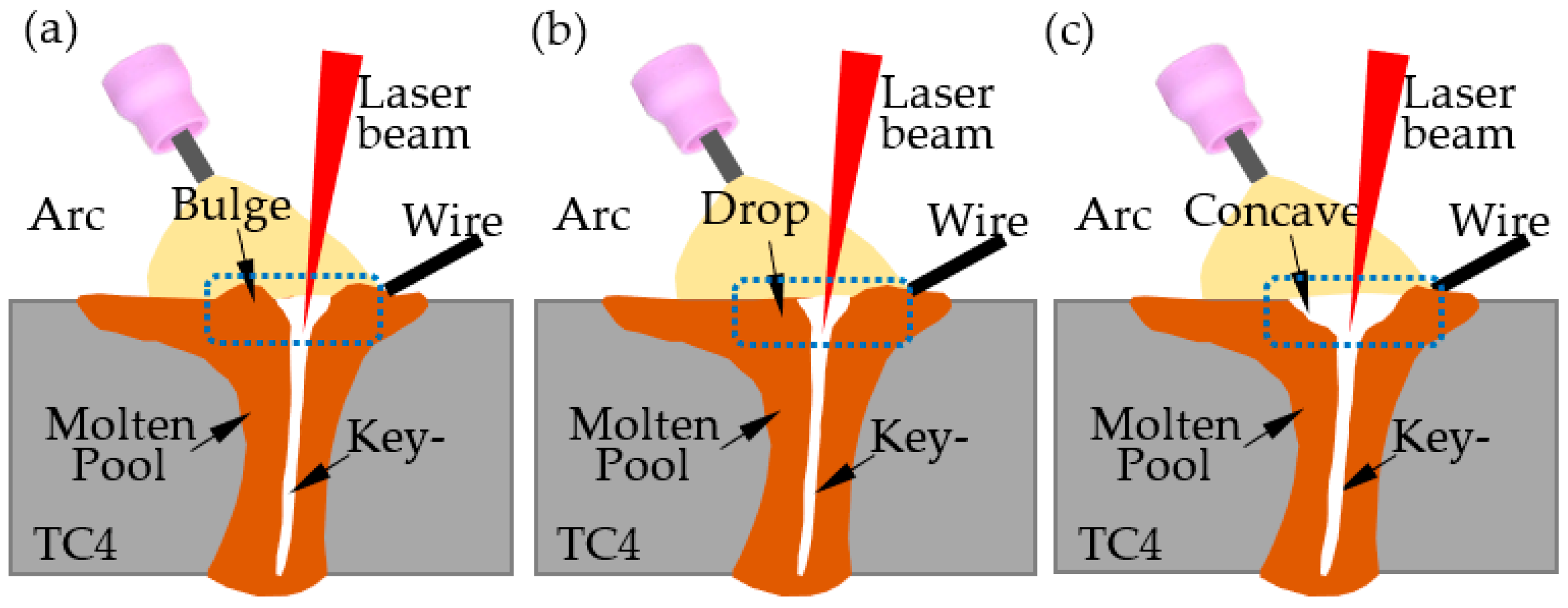
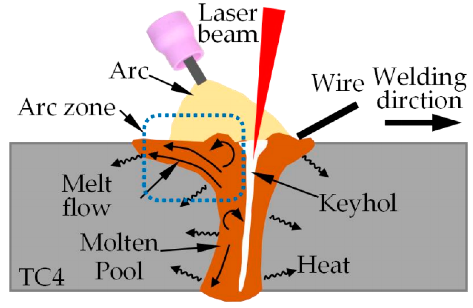
As the current increases, the cross-section of the weld gradually changes from a "nail" shape to a "cup" shape. The molten pool in the arc zone will generate a flow with a period of 2 ms, which will have the effect of grain refinement and eliminate pores in the arc zone, so the flow will become more intense as the current increases.
(2)
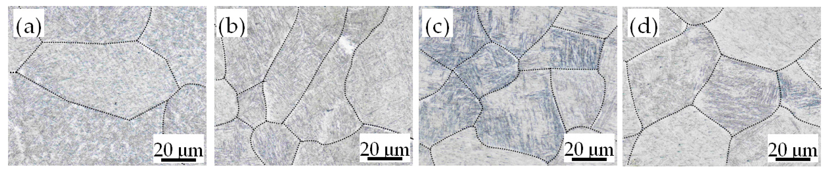
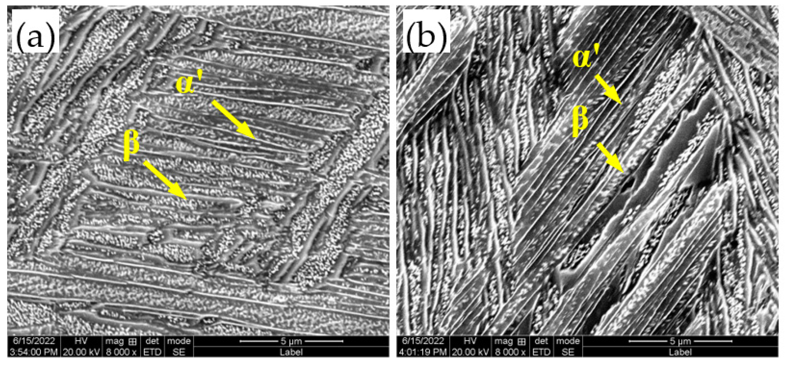
The grain size of the arc zone is smaller than that of the laser zone. The two zones are mainly composed of an acicular α′ martensite interwoven mesh-basket structure, αgb phase, and Widmanstätten structure. The spacing of the α′ martensite beams in the laser zone is narrower, with an average spacing of 0.41 μm.
(3)
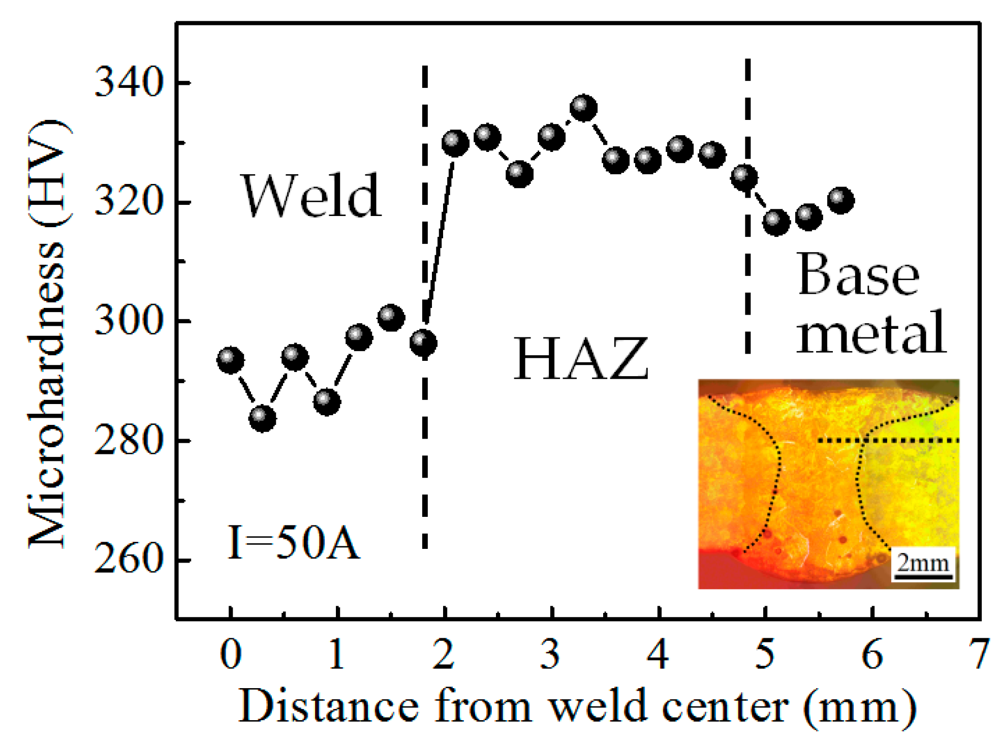
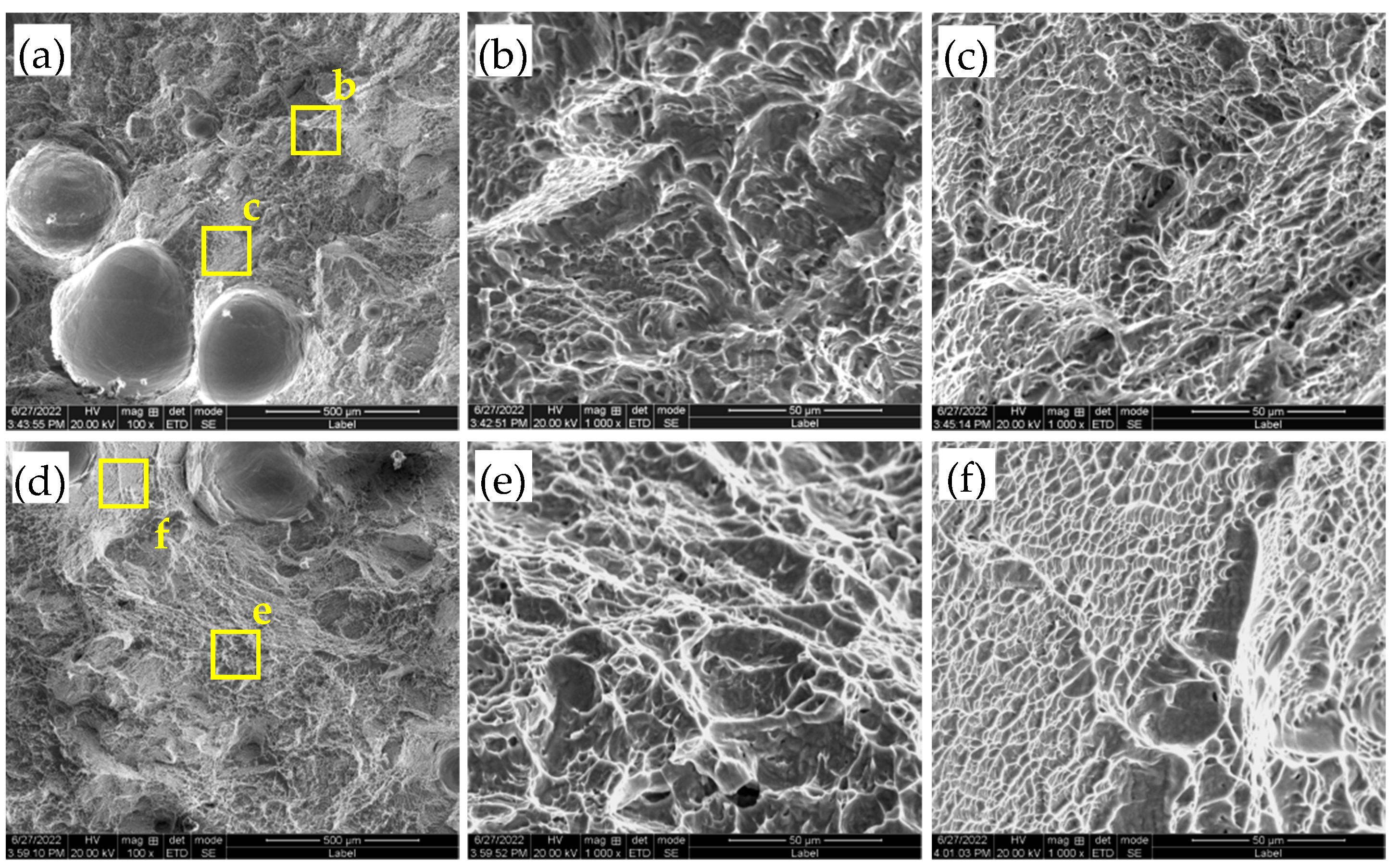
The β phase increases gradually with an increase in the current, which will lead to a downward trend in the average hardness of both zones. The average hardness value of the laser zone containing more α′ martensite and less β phase is slightly higher than that of the arc zone. The hardness uniformity of the laser zone is also significantly better than that of the arc zone. The tensile strength of the joint shows a trend of increasing first and then decreasing, and the joint with I = 50 A presented the highest tensile strength of 957.3 MPa, approaching 100% of the base metal, and fractured in the fusion zone.

Author Contributions

Conceptualization, H.F., J.H. and Y.N.; methodology, P.Z. and J.L.; formal analysis, H.F.; investigation, H.F.; resources, Y.H.; data curation, H.F.; writing—original draft preparation, H.F.; writing—review and editing, J.H. and Y.N.; supervision, P.Z.; project administration, P.Z.; funding acquisition, P.Z. All authors have read and agreed to the published version of the manuscript.

Funding

This research was funded by the Youth Innovation Team of Shaanxi Universities of Education Department of Shaanxi Provincial Government (Grant No. 2019-73), the Technology Program of Xi’an Aeronautical Polytechnic Institute (Grant No. 21XHZK-13), and the Technology Program of Xi’an Aeronautical Polytechnic Institute (Grant No. 19XHZK-002).

Data Availability Statement

Not applicable.

Acknowledgments

The authors thank the School of Aeronautical Materials Engineering and the State Key Laboratory of Advanced Processing and Recycling of Non-Ferrous Metal for providing equipment support.

Conflicts of Interest

The authors declare no conflict of interest.

References

  1. Ding, R.; Guo, Z. Microstructural evolution of a Ti–6Al–4V alloy during β-phase processing: Experimental and simulative investigations. Mater. Sci. Eng. A 2004, 365, 172–179. [Google Scholar] [CrossRef]
  2. Liu, J.; Alfantazi, A.; Asselin, E. A new method to improve the corrosion resistance of titanium for hydrometallurgical applications. Appl. Surf. Sci. 2015, 332, 480–487. [Google Scholar] [CrossRef]
  3. Huang, J.; Liu, S.; Yu, S.; Yu, X.; Chen, H.; Fan, D. Arc deposition of wear resistant layer TiN on Ti6Al4V using simultaneous feeding of nitrogen and wire. Surf. Coat. Technol. 2020, 381, 125141. [Google Scholar] [CrossRef]
  4. Fang, N.; Guo, E.; Huang, R.; Yin, L.; Chen, Y.; Zeng, C.; Cao, H.; Zou, J.; Xu, K. Effect of welding heat input on microstructure and properties of TC4 titanium alloy ultra-narrow gap welded joint by laser welding with filler wire. Mater. Res. Express 2021, 8, 016511. [Google Scholar] [CrossRef]
  5. Wang, L.; Li, X.; Gao, M.; Zeng, X. Stabilization mechanism and weld morphological features of fiber laser-arc hybrid welding of pure copper. J. Manuf. Process. 2017, 27, 207–213. [Google Scholar] [CrossRef]
  6. Bagger, C.; Olsen, F.O. Review of laser hybrid welding. J. Laser Appl. 2005, 17, 2–14. [Google Scholar] [CrossRef]
  7. Li, Y.; Zhao, Y.; Li, Q.; Wu, A.; Zhu, R.; Wang, G. Effects of welding condition on weld shape and distortion in electron beam welded Ti2AlNb alloy joints. Mater. Des. 2017, 114, 226–233. [Google Scholar] [CrossRef]
  8. Panwisawas, C.; Perumal, B.; Ward, R.M.; Turner, N.; Turner, R.P.; Brooks, J.W.; Basoalto, H.C. Keyhole formation and thermal fluid flow-induced porosity during laser fusion welding in titanium alloys: Experimental and modelling. Acta Mater. 2017, 126, 251–263. [Google Scholar] [CrossRef] [Green Version]
  9. Shi, J.; Zhou, Y.; Liu, L. Application of pulsed laser-TIG hybrid heat source in root welding of thick plate titanium alloys. Appl. Sci. 2017, 7, 527. [Google Scholar] [CrossRef] [Green Version]
  10. Zhang, C.; Gao, M.; Wang, D.; Yin, J.; Zeng, X. Relationship between pool characteristic and weld porosity in laser arc hybrid welding of AA6082 aluminum alloy. J. Mater. Process. Technol. 2017, 240, 217–222. [Google Scholar] [CrossRef]
  11. Chen, M.; Xin, L.; Zhou, Q.; He, L.; Wu, F. Effect of laser pulse on alternative current arc discharge during laser-arc hybrid welding of magnesium alloy. Opt. Laser Eng. 2018, 100, 208–215. [Google Scholar] [CrossRef]
  12. Frostevarg, J.; Kaplan, A.F.H. Undercuts in laser arc hybrid welding. Phys. Procedia 2014, 56, 663–672. [Google Scholar] [CrossRef] [Green Version]
  13. Chen, Y.; Feng, J.; Li, L.; Chang, S.; Ma, G. Microstructure and mechanical properties of a thick-section high-strength steel welded joint by novel double-sided hybrid fibre laser-arc welding. Mater. Sci. Eng. A 2013, 582, 284–293. [Google Scholar] [CrossRef]
  14. Li, G.; Zhang, C.; Gao, M.; Zeng, X. Role of arc mode in laser-metal active gas arc hybrid welding of mild steel. Mater. Des. 2014, 61, 239–250. [Google Scholar] [CrossRef]
  15. Casalino, G.; Mortello, M.; Leo, P.; Benyounis, K.Y.; Olabi, A.G. Study on arc and laser powers in the hybrid welding of AA5754 Al-alloy. Mater. Des. 2014, 61, 191–198. [Google Scholar] [CrossRef]
  16. Faraji, A.H.; Goodarzi, M.; Seyedein, S.H.; Maletta, C. Effects of welding parameters on weld pool characteristics and shape in hybrid laser-TIG welding of AA6082 aluminum alloy: Numerical and experimental studies. Weld. World 2016, 60, 137–151. [Google Scholar] [CrossRef]
  17. Liu, S.; Zhang, H.; Hu, J.; Yan, S. Microstructure of laser-MAG hybrid welds of sintered P/M steel. J. Mater. Eng. Perform. 2013, 22, 251–257. [Google Scholar] [CrossRef]
  18. Liu, F.; Tan, C.; Ma, G.; Han, X.; Chen, B.; Song, X.; Zhao, H.; Wang, G. Improvement of inhomogeneity of microstructure and mechanical properties for 316 stainless steel laser-MIG hybrid welded joint assisted by alternating magnetic field. Sci. Technol. Weld. Joining 2022, 27, 437–445. [Google Scholar] [CrossRef]
  19. Fang, N.; Guo, E.; Xu, K.; Huang, R.; Ma, Y.; Chen, Y.; Yang, Y.; Xie, J. In-situ observation of grain growth and phase transformation in weld zone of Ti-6Al-4V titanium alloy by laser welding with filler wire. Mater. Res. Express 2021, 8, 056507. [Google Scholar] [CrossRef]
  20. Fu, Y.; Guo, N.; Zhu, B.; Shi, X.; Feng, J. Microstructure and properties of underwater laser welding of TC4 titanium alloy. J. Mater. Process. Technol. 2020, 275, 116372. [Google Scholar] [CrossRef]
  21. Long, J.; Zhang, L.; Zhang, L.; Wu, J.; Zhuang, M. Comparison of fatigue performance of TC4 titanium alloy welded by electron beam welding and laser welding with filler wire. Fatigue Fract. Eng. Mater. Struct. 2022, 45, 991–1004. [Google Scholar] [CrossRef]
  22. Frostevarg, J.; Kaplan, A.F.H. Undercut suppression in laser-arc hybrid welding by melt pool tailoring. J. Laser Appl. 2014, 26, 031501. [Google Scholar] [CrossRef]
  23. Gao, M.; Zeng, X.; Hu, Q.; Yan, J. Weld microstructure and shape of laser–arc hybrid welding. Sci. Technol. Weld. Join. 2008, 13, 106–113. [Google Scholar] [CrossRef]
  24. Wei, H.L.; Li, H.; Yang, L.J.; Gao, Y.; Ding, X.P. Arc characteristics and metal transfer process of hybrid laser double GMA welding. Int. J. Adv. Manuf. Technol. 2015, 77, 1019–1028. [Google Scholar] [CrossRef]
  25. Mahrle, A.; Schmidt, J. The influence of fluid flow phenomena on the laser beam welding process. Int. J. Heat Fluid Flow 2002, 23, 288–297. [Google Scholar] [CrossRef]
  26. Rai, R.; Kelly, S.M.; Martukanitz, R.P.; DebRoy, T. A convective heat-transfer model for partial and full penetration keyhole mode laser welding of a structural steel. Metall. Mater. Trans. A 2008, 39, 98–112. [Google Scholar] [CrossRef]
  27. Zhao, L.; Sugino, T.; Arakane, G.; Tsukamoto, S. Influence of welding parameters on distribution of wire feeding elements in CO2 laser GMA hybrid welding. Sci. Technol. Weld. Join. 2009, 14, 457–467. [Google Scholar] [CrossRef]
  28. Liu, F.; Xu, B.; Song, K.; Tan, C.; Zhao, H.; Wang, G.; Chen, B.; Song, X. Improvement of penetration ability of heat source for 316 stainless steel welds produced by alternating magnetic field assisted laser-MIG hybrid welding. J. Mater. Process. Technol. 2022, 299, 117329. [Google Scholar] [CrossRef]
  29. Wang, H.; Liu, X.; Liu, L. Research on Laser-TIG Hybrid Welding of 6061-T6 Aluminum Alloys Joint and Post Heat Treatment. Metals 2020, 10, 130. [Google Scholar] [CrossRef] [Green Version]
  30. Yu, X.; Fan, D.; Huang, J.; Kang, Y. The characteristic of interface microstructure for aluminum-steel butt joint by arc assisted laser welding-brazing. Mater. Res. Express 2019, 6, 096533. [Google Scholar] [CrossRef]
  31. Hao, K.; Gong, M.; Pi, Y.; Zhang, C.; Gao, M.; Zeng, X. Effect of Ni content on rolling toughness of laser-arc hybrid welded martensitic stainless steel. J. Mater. Process. Technol. 2017, 251, 127–137. [Google Scholar] [CrossRef]
  32. Wu, K.C. Correlation of properties and microstructure in welded Ti-6Al-6V-2Sn. Weld. J. 1981, 60, 219–226. [Google Scholar]
Figure 1. Groove shape and size.
Metals 12 01854 g001
Figure 2. Laser–TIG hybrid welding system: (a) physical picture; (b) position relation of the laser, TIG torch, and welding wire.
Metals 12 01854 g002
Figure 3. The temperature and image acquisition system.
Metals 12 01854 g003
Figure 4. Shape and dimensions of tensile specimens.
Metals 12 01854 g004
Figure 5. Surface morphology of laser–TIG hybrid welded joints with different currents: (a) I = 30 A; (b) I = 40 A; (c) I = 50 A; (d) I = 60 A.
Metals 12 01854 g005
Figure 6. Laser–TIG morphology in a stable state with different currents: (a) I = 30 A; (b) I = 40 A; (c) I = 50 A; (d) I = 60 A.
Metals 12 01854 g006
Figure 7. Laser–TIG morphology with different times when the current is 50 A: (a) t = 1 ms; (b) t = 2 ms; (c) t = 3 ms; (d) t = 4 ms.
Metals 12 01854 g007
Figure 8. Cross-sectional morphology of laser–TIG hybrid welded joints with different currents: (a) I = 30 A; (b) I = 40 A; (c) I = 50 A; (d) I = 60 A.
Metals 12 01854 g008
Figure 9. Weld geometry with different welding currents: (a) weld seam width; (b) weld seam area.
Metals 12 01854 g009
Figure 10. Microstructure of laser–TIG hybrid welded joints with different currents: (a) I = 30 A, arc zone; (b) I = 30 A, laser zone; (c) I = 30 A, HAZ; (d) I = 50 A, arc zone; (e) I = 50 A, laser zone; (f) I = 50 A, HAZ.
Metals 12 01854 g010
Figure 11. The grains of arc zone with different current sizes: (a) I = 30 A; (b) I = 40 A; (c) I = 50 A; (d) I = 60 A.
Metals 12 01854 g011
Figure 12. SEM images of laser–TIG hybrid welded joints: (a) arc zone; (b) laser zone.
Metals 12 01854 g012
Figure 13. Atomic percentages of Al elements of arc zone and laser zone with different currents.
Metals 12 01854 g013
Figure 14. Microhardness distribution of vertical weld with different currents: (a) I = 30 A; (b) I = 50 A.
Metals 12 01854 g014
Figure 15. Microhardness value of the weld: (a) average microhardness value of the arc zone and laser zone; (b) standard deviation (S) value of microhardness in weld with different currents.
Metals 12 01854 g015
Figure 16. Microhardness distribution of welded joint.
Metals 12 01854 g016
Figure 17. Tensile test results of welded joints with different currents: (a) tensile strength; (b) fracture location.
Metals 12 01854 g017
Figure 18. Typical tensile fractured morphology in arc zone of welded joints with different currents: (ac) I = 30 A; (df) I = 50 A.
Metals 12 01854 g018
Figure 19. Schematic diagram of the molten pool flow process near the laser beam: (a) bulge; (b) drop; (c) concave.
Metals 12 01854 g019
Figure 20. Schematic diagram of molten pool flow in arc zone.
Metals 12 01854 g020
Figure 21. Schematic diagram of grain evolution in arc zone: (a) grain growth; (b) grain breakage.
Metals 12 01854 g021
Table 1. Chemical compositions of TC4 (wt%).
ElementAlVFeCNHOTi
TC45.6~6.53.5~4.50.300.080.050.0150.20Bal.
Table 2. Experiment parameters of welding.
NumberI (A)P (kW)Welding Speed
(cm/min)
1301.520
240
350
460
Publisher’s Note: MDPI stays neutral with regard to jurisdictional claims in published maps and institutional affiliations.

