Smart Stress Annihilation in Steels Using Residual Stress Distribution Monitoring and Localized Induction Heating
by
 ,
,
Kaiming Liang
1,2, 
Panagiotis Tsarabaris
2, 
Aphrodite Ktena
2,3 ,
,
Xiaofang Bi
1,* and
Evangelos Hristoforou
2,*
1
Key Laboratory of Aerospace Materials and Performance (Ministry of Education), School of Materials Science and Engineering, Beihang University (BUAA), Beijing 100191, China
2
School of Electrical & Computer Engineering, Zografou Campus, National Technical University of Athens, 15780 Athens, Greece
3
Energy Systems Laboratory, Evripos Campus, National & Kapodistrian University of Athens, 34400 Evia, Greece
*
Authors to whom correspondence should be addressed.
Metals 2020, 10(6), 838; https://doi.org/10.3390/met10060838
Submission received: 23 April 2020
/
Revised: 5 June 2020
/
Accepted: 16 June 2020
/
Published: 24 June 2020
(This article belongs to the Special Issue FaSTeP: Faultless Steel Production and Manufacturing)
Abstract
:The monitoring and control of residual stresses and microstructure are of paramount importance for the steel industry. Residual stress annihilation is needed during the entire lifetime of steels. In this paper, we presented a stress monitoring and annihilation method, based on a force sensor for stress monitoring and an induction heater for localized heat treatment and corresponding stress annihilation. The heat treatment results indicated an at least 90% reduction of localized stresses, allowing for the implementation of the method in steel production and manufacturing to improve steel quality and perform faultless steel production and manufacturing.
1. Introduction
Localized stresses in steels are due to dislocations, precipitations, and inhomogeneities in their micro-structure [1]. These stresses are responsible for the generation and propagation of nano cracks, eventually leading to steel failure [2]. The stress gradient, rather than the absolute amplitude of the localized stresses, is responsible for the nano-crack initiation and propagation [3].
The surface and sub-surface residual stresses type II can be determined in laboratory conditions using X-ray Diffraction in the Bragg-Brentano set-up (XRD-BB for short) [4]. The bulk residual stresses type II can be measured using neutron diffraction (ND for short) [5]. XRD-BB and ND can determine 2-dimensional and 3-dimensional stress components, respectively, and are used as reference residual stress measurements. They have been successfully employed to correlate surface or bulk magnetic properties with the corresponding stress components [6,7,8,9]. Surface and bulk differential permeability have been correlated with residual stresses determined by XRD-BB and ND, respectively, in References [6,7]. Meanwhile, the Barkhausen noise has been correlated with surface residual stresses determined by XRD-BB in Reference [8] with an uncertainty of better than 1%. The monotonic dependence of magnetic properties, monitored by permeability or Barkhausen sensors, on residual stresses, determined by XRD-BB or ND, yields the so-called Magnetic Stress Calibration (MASC) curve [10], which is characteristic of a given material.
Recently, to decrease the time required for residual stress monitoring, we have developed force sensors based on monitoring of the force exerted on magnetostrictive delay lines (MDL for short) between a permanent magnet and the under-test steel [11]. The force is dependent on the permeability of the under-test steel, and consequently, on the localized residual stresses, as determined by the MASC technique. Therefore, these sensors can be used to monitor residual stress in steel production and manufacturing.
The annihilation of stresses is crucial to prevent crack initiation and propagation in most steels. Heat treatment is the predominant technique for stress annihilation [12]. The classic heating blanquettes and ovens cannot offer fast and, most importantly, localized heat treatment. Heat treatment in the stress-free areas of the steel can result in steel softening, affecting its mechanical properties. Localized heat treatment, on the other hand, may offer the necessary heat distribution for stress annihilation without affecting the rest of the steel. Fast and localized increase of the steel temperature can be achieved by variable frequency–variable power induction heating [13]. The effect of localized heat treatment on residual stresses in a welded rail was studied using finite element analysis [14], determining that local heat treatment may result in high tensile residual stress relief and hardening of the rail surface. Sheets of various thicknesses and various pancake-coils and hairpins have also been studied, leading to similar levels of temperature on both the front and backside of a 2 mm thick sheet of Docol 1400M heated with 2900 W [15]. Furthermore, magnetodielectric materials have been used to enhance the magnetic flux, and therefore, the eddy current density [16]. Commercial induction heaters are also available, based on the various needs of induction heating [17].
Our motivation has been the combination of stress monitoring, using our MDL based force sensor as a feedback control unit, with a commercially available induction heating device, to achieve smart localized stress annihilation in steels.
In this paper, with no loss of generality, we first present a simplified theoretical analysis of the localized heating principle based on induction heating and the main parameters involved concerning a flat steel structure. The analysis is followed by the proposed experimental procedure, illustrating stress monitoring in stress-affected areas of steel coupons, localized annealing to treat those localized stress-affected areas, and finally, the determination of stress annihilation followed by another round of residual stress monitoring routine.
2. Heat Dissipation and Distribution
A common arrangement for localized heat treatment is illustrated in Figure 1. Without any loss of generality and to make the study more comprehensive, the surface of the steel is considered flat. A single-turn circular induction heating coil with a diameter significantly smaller than the length and width of the steel is considered at a considerably small, less than 1 mm, lift-off distance above the steel.
The following qualitative analysis of the heating process is based on the laws of classical electrodynamics, which helps in understanding and controlling the application of the heat induction method for localized heat treatment and stress annihilation. A full model and systematic discussion of the heat distribution in the steel under treatment is the subject of future works.
Transmitting high-frequency sinusoidal current through the induction coil results in a sinusoidal magnetic field of the same frequency, penetrating the steel surface. This magnetic field generates eddy currents in a thin volume under the surface of the steel, determined by the skin depth . It is defined as the depth at which the magnitude of the magnetic field is lower than its surface value by a factor of e−1, which is given by:
where: is the conductivity; the resistivity; the relative permeability; the excitation frequency, and the permeability of the vacuum (4π × 10−7 H/m). Similar eddy current effects can also be considered for pulsed-current waveforms, to the extent that a pulsed-field may be considered as a summary of the harmonic sinusoidal fields [18]. Depth in most steels is from a few tens to a few hundreds of microns for a frequency regime in the order of several kHz, which is typically used in induction heating. The value of the excitation frequency is determined based on the depth of the desired heat treatment of the steel. For simplicity reasons, we assume that the microstructure of the steel under treatment does not have a significant effect on the eddy current distribution and when the induced eddy current amplitude, Io, is in the order of tens of Amperes.
The distribution of eddy currents depends mainly on the lift-off distance, , between the induction coil and steel surface, and follows the law. The distance, , between the Radio Frequency (RF) coil and the steel surface must be maintained at a minimum to maximize the effect of Joule heating due to the generated eddy currents.
In this preliminary study of the proposed method for controlled induction heating with residual stress monitoring in the feedback loop, flat steels of a thickness in the order of 0.1–1 mm were considered, allowing for thermal dissipation through the whole thickness of the under-test steel. For such thicknesses, the excitation frequency range must be from 1 kHz to 10 kHz, with = 1 × 10⁻³ m, ~2 × 10⁶ S/m, ~100–4000.
In general, the thermal energy absorbed by a conducting volume, due to a current density, I, flowing through it, increases with time and the square of the current.
In induction heating, the Joule effect is due to the eddy current density generated by the magnetic flux density penetrating in a volume , where A is the area affected by eddy currents and the penetration depth. Volume , in this case, has a ring-shape geometry reflecting the geometry of the excitation RF coil and the resulting magnetic flux density, which is higher in the vicinity of the conductor. Hence, the eddy current density inside volume depends on the excitation current amplitude and frequency content. The generated heat is proportional to the square of the induced eddy currents, as well as the ohmic resistance of the enclosed volume. Considering that the under-treatment steel is a metal, another important parameter is the material’s heat conductivity. The low amplitude of thermal conductivity in steels, as well as its decrease with increasing temperature, prohibits a large spatial distribution of heat in the steel volume.
Thus, heat is mainly generated within the volume . As time passes, the generated heat is dissipated conductively in all directions of the steel. This heat dissipation is isotropic or anisotropic, depending on the steel’s heat conductivity anisotropy. For example, a welded area is strongly anisotropic, while a base steel material is rather isotropic. However, qualitatively speaking, the specific heat capacity and heat conductivity of steels do not permit fast heat conduction, as in the case of other metals, like copper. It is expected that for an excitation current duration in the order of several seconds, the heat affected area, A, will remain in the vicinity of the origin.
Therefore, for a given excitation current, , of frequency, f, the main parameters affecting the temperature increase and distribution on the surface and in the bulk of the steel under treatment are the distance, , between the induction coil and steel surface and the duration, , of the sinusoidal (or pulsed) current transmission.
3. Experimental Set-Up and Results
The experimental stress monitoring and annihilation set-up are illustrated in Figure 2. The system consisted of two main subsystems: the stress monitoring and the stress annihilation instruments. Concerning stress monitoring, the MDL-based force sensor was employed to determine the localized residual stresses [11]. The response of the sensor was connected to a computer and stored in digital form. The stress annihilation instrument was a current generator in the form of a 1 kW induction heater, operating at frequencies in the order of 1–10 kHz, originally connected to a single turn induction coil, parallel to the under-treatment steel surface. The diameter of the single turn induction coil was 20 mm.
The experimental procedure was as follows: First, the MDL sensor scanned the surface of the steel, determining the force exerted between a permanent magnet and the under-test steel, from which the permeability and the residual stresses were determined [11]. Next, the induction heater was positioned over the areas of the under-test steel requiring localized heat treatment. Alternating current was transmitted within a relatively small time window ranging from 3 s to 60 s, to restrict heat dissipation in the heat-treated area, aiming at stress annihilation limited in this area only. The final part of the process was the repetition of the permeability scan to determine the level of localized residual stresses after the localized heat treatment. During the induction heating process, the IR camera Fluke Ti45 (FLUKE, Everfried, WA, USA)was used to monitor the temperature distribution at the surface of the steel.
The under-test steel coupons were 0.3 mm thick cold-rolled non-oriented electric steel, 1 mm thick AISI 1008 steel, and 1 mm thick low carbon steel, cut in 150 mm × 100 mm rectangular strips.
Figure 3 illustrates the indicative results of the permeability mapping on the low carbon steel coupon. The permeability measurements are carried out along the centerline of each coupon, starting from the one end of the strip. The stresses of the under-test steel coupon before the heat treatment may be considered homogeneous. After stress monitoring, induction heating was applied by setting the induction coil over the center of the coupon. The induction coil was set on one side of the coupon at a distance maintained at either 0.2 mm or 10 mm. The IR camera Fluke Ti45 was set firmly facing the other side of the steel coupon to monitor the coupon’s temperature during the heating process.
Figure 4 illustrates the thermal profile of the AISI 1008 steel coupon at different time intervals for two different distances between the coil and the sample’s surface, , as a result of the 1 kW electric power fed to the coil for . Figure 4a,b illustrate the temperature distribution at immediately after current transmission and after 1 min, respectively. At this distance, the temperature elevation was below 200 °C, not resulting in stress annihilation. Figure 4c illustrates the heat distribution 1 min after excitation at for . The cross-section of the one-turn excitation coil was not parallel to the under-test steel coupon. Two significant results are obtained from Figure 4c: the first is that the local temperature was elevated up to 550 °C for a short , thereby permitting localized heat treatment. The second one is that higher temperatures were achieved in the areas of the steel coupon being closer to the one-turn excitation coil. This crucial observation has driven the re-design of the excitation coil, by employing a V-shaped or U-shaped excitation conductor, schematically illustrated in Figure 5. The achieved temperature elevation above 400 °C and below 450 °C, 1 min after excitation, as illustrated in Figure 4d, for warranties heat treatment and the absence of microstructural changes, such as grain size changes or phase transformation in most types of steels.
The sample of Figure 4d was examined by a scanning electron micrograph, before and after heat treatment, in the vicinity of the heat-treated volume. The results indicated the absence of microstructural changes concerning the mean grain size diameter, as expected. Furthermore, transmission electron microscopy was performed for the same samples (Figure 6), indicating an apparent reduction of dislocation forests, suggesting that a stress relief process took place.
It could be seen that the heat distribution was in agreement with the theoretical analysis of the previous section. That is, for higher spacing values ( ), the eddy currents, and therefore, the heat dissipation was small (Figure 4a,b), while at a closer distance, such as , the heat dissipation was practically restricted in volume, V, underneath the part of the ring closer to the surface or the point of the V-conductor (Figure 4c,d).
Permeability monitoring with the MDL force sensor was repeated after the localized induction heating to observe the effect of local treatment on the permeability of the heat-treated part and, therefore, on the localized stresses. Figure 7 illustrates the profile of the permeability after localized heat treatment. The red line illustrates the effect of the permeability change after heat treatment with the single turn coil parallel to the surface of the steel, while the black line illustrates the permeability change using the V-shaped or U-shaped induction conductor of Figure 5.
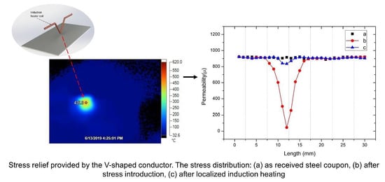
Consequently, an AISI 1008 steel coupon was heat annealed (stress relieved) in an inert gas oven at 400 °C for 1 h, following a 1 K/min slow cooling process. After heat treatment, the residual stresses of the AISI 1008 steel coupon were monitored following the previous procedure. Immediately after, the coupon was set on a flat and smooth wooden surface and locally deformed by a 2.5 cm diameter St316L sphere dropped from a height of 500 mm. Consequently, the localized permeability levels were monitored, correlated to the localized residual stresses, using the same arrangement as before. After permeability monitoring, the V-shaped induction conductor performed localized heat treatment at the point of the steel sphere impact. Figure 8 illustrates the stress distribution after the initial stress relief process of the coupon (Figure 8a), after the sphere drop on it (Figure 8b), and after the localized induction heating at the deformed point (Figure 8c). The stress induced by the steel sphere was annihilated by the induction heating process by more than 90%, as observed in Figure 8 from the values of permeability.
These preliminary results are evidence of the potential of the proposed methodology to be used for smart stress monitoring and annihilation in steels. Compared to traditional annealing methods, the proposed method can save time and obtain reasonable results, which may have great significance in industrial applications.
4. Discussion
The desired level of homogenization of the residual stresses is achievable by means of localized heat treatment using the proper amount of current and duration for induction heating. The experimental work has illustrated that grain size changes have been insignificant, while dislocation forests were reduced, allowing for lower residual stresses. Apart from that, the effected localized temperature profile is, or can be, such that it does not affect the microstructure. In most steels, heat treatment below 450 °C permits negligible phase transformation or grain net modifications.
The determination of the final level of rehabilitated stresses in steels, using permeability measurements, can be realized even at elevated temperatures, provided that these temperatures are below the Curie point, such as the <450 °C operating temperatures studied in the paper. If the temperature profile of permeability is known, the permeability at room temperature can be determined despite the temperature at which permeability was measured.
The design of the induction coil geometry is crucial for the effective success of the method in the industrial environment. Careful, case-specific design of coils is essential for optimum heat transfer. For industrial use, a water-cooled oxygen-free copper tube should be used as the current conductor, permitting long time operation of the induction coil. The commercially available diameter of such copper tubes is from 3–6 mm, thereby determining the size of the induction coils. When localized heating is necessary, the use of induction coils is not appropriate.
The use of a V-shaped or U-shaped conductor is appropriate for single point treatment. However, multiple area heat treatment requires the use of multiple U-shaped conductors. Accordingly, the part of the U-shaped conductor contributing to eddy current generation, and therefore, heat dissipation is the tip of it, closer to the steel surface. This rounded part of the U-shaped conductor, according to the Biot–Savart law permits the generation of local eddy currents in a considerably small effective heating diameter and therefore results in precisely localized heat treatment. This arrangement may be the solution for fine-tuned localized stress relief processes in tooling manufacturing and other applications. For such applications, pulsed current induction may be used instead of the classical RF sinusoidal current. The transfer of this design to a production line may involve the use of an induction conductor, instead of an induction coil. As an example, if uniform eddy currents are to be induced on the surface of the steel, a straight conductor in the transverse direction may replace the V-shaped or U-shaped conductors. In this case, the system complexity is reduced significantly.
The described method can also be used to locally induce stresses in steels by using water or soap-water or oil quenching immediately after the localized heating. Water or oil nozzles can be set immediately after the induction coil to cool down the heated surface fast. This way, the rapid quenching may result in strengthening the steel under treatment and increase its hardness. In this case, the examination of the final permeability will demonstrate the level of induced stress.
Apart from that, as the power electronics technology permits the off-the-shelf design and development of RF generators, the current generators can be effective at low cost. As an example, considering the extreme case of a width of produced steel sheet in the order of 900 mm and the need for heat treatment with a spatial resolution of 1 mm2, then 900 U-shaped conductors are needed to heat-treat the surface of the steel effectively. Suppose that all conductors have to transmit their maximum power at the same time, the total amount of power required is 900 kW, bearing in mind that 1 kW per conductor is required to achieve 570 °C in the under-treatment steel. The amount of required power is less than the power required for a normal furnace to heat a large batch of steel. Additionally, the cost of an RF current generator of 1 MW power is not dramatically high and is certainly lower than the cost of custom ovens for the same purpose. However, bearing in mind that only selected areas of the steel will need thermal treatment, the amount of power required for stress annihilation is considerably smaller. This is an excellent advantage of the proposed technique.
The heat treatment time is also reduced following the proposed smart stress monitoring and annihilation. The time needed for a normal heat treatment process is almost a day, including the time required for temperature elevation, steady-state, and return to room temperature. With the proposed technology, the heat treatment time is negligible, permitting on-line measurements, stress annihilation, and final stress level monitoring.
The application of the presented method in steel production and manufacturing can be realized using the schematic in Figure 9. Linear arrays of permeability sensors can be used to monitor the stress level across and along the length of the produced material. Immediately after the array sensors, an array of induction coils, or V-shaped or U-shaped conductors, can be set to transmit sinusoidal or pulsed current, and therefore, perform localized heat treatment, followed by a nozzles array of water or soap-water or oil for steel hardening in case it is needed. The induction heater array is followed by a second array of permeability sensors following at a distance, accompanied by infrared sensors, thereby permitting the steel to cool down at an acceptable and well-determined temperature, to measure and certify its final level of permeability, after correlating the magnetic response with the monitored temperature. This is considered a “third party” certification of the whole process. The arrangement of the linear arrays of sensors and the linear arrays of induction coils of Figure 9 illustrates the effectiveness of the method and paves the way towards a new standard in the field of stress monitoring and annihilation.
The applications of the method can be numerous. The fact that the stress distribution is monitored and controlled based on an automated feedback process, instead of assuming stress levels based on the production methodology, which results in blind and sometimes unnecessary or mistaken stress relief processes, will open a new era in the steel industry. The steel manufacturing in rod, sheet, tubes, etc., may use this technology to optimize the quality of the final products. Cold rolling and hot rolling may also implement the stress monitoring and annihilation process to provide knowledge on the quality of the produced steel. This method can certainly be applied in shipyards to monitor and annihilate stress distribution in welds. However, a critical application is the manufacturing of seamless tubes used for the production of heat exchangers, as well as the maintenance of these heat exchangers when they are in service. The knowledge of the stress gradient and the corresponding annihilation in these steels is essential for their operation, i.e., even a small micro-crack may be responsible for setting a whole line off. Another significant application is the stators and rotors of electric machines of cars. As they suffer from severe acceleration and deceleration, the soft magnetic material of the motor may suffer from mechanical and thermo-mechanical fatigue. The stress annihilation in these cases may be based on the proposed technology.
5. Future Work
Concerning the effectiveness of the method in the industrial environment for the optimum treatment of the steel, modeling of heat generation and transfer is necessary. This modeling should consider all possible parameters involved, to give a solution to different types of production and manufacturing lines, as well as different shapes of produced and manufactured steels. Similarly, this modeling should offer solutions for the case of the maintenance of steel structures. The key enabling technology for the proper realization of the model is the correct calculation of the eddy current density and its distribution in the steel, as well as the relationship of the eddy current density to heat and temperature. The eddy current density and distribution calculations should consider all parameters affecting their generation, i.e., the magnetization loop, the resistivity and the heat conductivity of the steel, the shape of the coil or the V-shaped or U-shaped conductor, its distance, and relative orientation concerning the steel, the shape of the steel surface exposed to it, as well as the magnitude and duration of the excitation current waveform. Packages exist, like Maxwell 12.0 from ANSYS, permitting such calculations. The calculation of the eddy currents necessary to reach the desired temperature in the treated volume will be based on the thermal capacity of the steel in question. Thermal capacity will be considered as a constant at the first approach, although its non-uniformity may affect the calculations of the anticipated heat. As soon as the heat and temperature are calculated, then the heat transfer is feasible through existing software packages, such as ANSYS. The experimental results presented may offer a comparison between the model and the experiment, thereby aiding in the correction and fine-tuning of the calculations. However, the existing finite element solvers require time to perform all these calculations. Therefore, after modeling the eddy current generation and distribution, it is proper to develop a code that solves quickly and accurately this particular problem. This code will greatly help engineers to appropriately tailor the design of the stress monitoring and annihilation systems.
6. Conclusions
A method has been presented in this paper, illustrating localized stress annihilation using localized induction heaters in the form of coils or V-shaped or U-shaped conductors, following the stress distribution determination. A stress annihilation in the order of 90% has been demonstrated. Future work is underway related to the optimization of the induction coils, the realization of a stress monitoring and annihilation plant, including the automated feedback control system and the modeling of the whole process.
Author Contributions
Conceptualization, E.H. and K.L.; methodology, K.L.; investigation, K.L.; data curation, P.T.; writing—original draft preparation, K.L. and E.H.; writing—review and editing, X.B., A.K., and E.H.; supervision, X.B. and E.H.; project administration, K.L. All authors have read and agreed to the published version of the manuscript.
Funding
This work is supported by the “High-end scholars short-term appointment plan in the National Laboratory for Aeronautics and Astronautics” GSGD 2019-005.
Acknowledgments
We would like to thank Beihang University for the support of the research and project.
Conflicts of Interest
The authors declare no conflict of interest.
References
- Withers, P.J.; Bhadeshia, H.K.D.H. Residual stress Part 2—Nature and origins. Mater. Sci. Technol. 2001, 17, 366–375. [Google Scholar] [CrossRef]
- Gaur, V.; Doquet, V.; Persent, E.; Mareau, C.; Roguet, E.; Kittel, J. Surface versus internal fatigue crack initiation in steel: Influence of mean stress. Int. J. Fatigue 2016, 82, 437–448. [Google Scholar] [CrossRef] [Green Version]
- Amargier, R.; Fouvry, S.; Chambon, L.; Schwob, C.; Poupon, C. Stress gradient effect on crack initiation in fretting using a multiaxial fatigue framework. Int. J. Fatigue 2010, 32, 1904–1912. [Google Scholar] [CrossRef]
- Rossini, N.S.; Dassisti, M.; Benyounis, K.Y. Methods of measuring residual stresses in components. Mater. Des. 2012, 35, 572–588. [Google Scholar] [CrossRef] [Green Version]
- Lavigne, O.; Kotousov, A.; Luzin, V. Microstructural Mechanical Texture and Residual Stress Characterizations of X52 Pipeline Steel. Metals 2017, 7, 306. [Google Scholar] [CrossRef] [Green Version]
- Vourna, P.; Ktena, A.; Tsakiridis, P.E.; Hristoforou, E. A novel approach of accurately evaluating residual stress and microstructure of welded electrical steels. NDT E Int. 2015, 71, 33–42. [Google Scholar] [CrossRef]
- Vourna, P.; Ktena, A.; Tsakiridis, P.E.; Hristoforou, E. An accurate evaluation of the residual stress of welded electrical steels with magnetic Barkhausen noise. Meas. J. Int. Meas. Confed. 2015, 71, 31–45. [Google Scholar] [CrossRef]
- Vourna, P.; Hervoches, C.; Vrana, M.; Ktena, A.; Hristoforou, E. Correlation of magnetic properties and residual stress distribution monitored by X-ray and neutron diffraction in welded AISI 1008 steel sheets. IEEE Trans. Magnet. 2015, 51, 7029219. [Google Scholar] [CrossRef]
- Vourna, P.; Hristoforou, E.; Ktena, A.; Svec, P.; Mangiorou, E. Dependence of Magnetic Permeability on Residual Stresses in Welded Steels. IEEE Trans. Magnet. 2017, 53, 1–4. [Google Scholar] [CrossRef]
- Hristoforou, E.; Vourna, P.; Ktena, A.; Svec, P. On the Universality of the Dependence of Magnetic Parameters on Residual Stresses in Steels. IEEE Trans. Magnet. 2016, 52, 7362189. [Google Scholar] [CrossRef]
- Liang, K.; Angelopoulos, S.; Lepipas, G.; Tsarabaris, P.; Ktena, A.; Bi, X.; Hristoforou, E. Sensor to Monitor Localized Stresses on Steel Surfaces Using the Magnetostrictive Delay Line Technique. Sensors 2019, 19, 4797. [Google Scholar] [CrossRef] [PubMed] [Green Version]
- Kosturek, R.; Wachowski, M.; Śnieżek, L.; Gloc, M. The Influence of the Post-Weld Heat Treatment on the Microstructure of Inconel 625/Carbon Steel Bimetal Joint Obtained by Explosive Welding. Metals 2019, 9, 246. [Google Scholar] [CrossRef] [Green Version]
- Grange, R.A. The rapid heat treatment of steel. Metall. Mater. Trans. B 1971, 2, 65–78. [Google Scholar] [CrossRef]
- Mansouri, H.; Monshi, A.; Hadavinia, H. Effect of local induction heat treatment on the induced residual stresses in the web region of a welded rail. J. Strain Anal. Eng. Des. 2004, 39, 271–283. [Google Scholar] [CrossRef]
- Carlsson, B. Local Heat Treatment of Ultra High-Strength Steel; Publications Office of the European Union, EU publications: Brussels, Belgium, 2009; pp. 21–24. [Google Scholar] [CrossRef]
- Nemkov, V.; Madeira, M.R.J.; Vyshinskaya, N.; Ruffini, M. Magnetic Flux Control In Induction Heat Treating. In Proceedings of the 25th ASM Heat Treating Conference And Exposition, Indianapolis, IN, USA, 14–17 September 2009. [Google Scholar]
- EFD-Induction. Available online: https://www.efd-induction.com/ (accessed on 3 June 2020).
- Bay, F.; Labbé, V.; Favennec, Y.; Chenot, J.L. A numerical model for induction heating processes coupling electromagnetism and thermomechanics. Int. J. Numer. Methods Eng. 2003, 58, 839–867. [Google Scholar] [CrossRef]
Figure 1.
The under-test steel and the induction coil set up.

Figure 2.
The experimental set-up: (a) permeability distribution monitoring; (b) induction heating and temperature monitoring. In the insets, the sensor, the camera, and the single turn induction coil are illustrated.
Figure 2.
The experimental set-up: (a) permeability distribution monitoring; (b) induction heating and temperature monitoring. In the insets, the sensor, the camera, and the single turn induction coil are illustrated.

Figure 3.
Permeability distribution in low carbon steel coupon (arbitrary units), measured before the treatment, corresponding to a rather homogeneous stress distribution along the centerline.
Figure 3.
Permeability distribution in low carbon steel coupon (arbitrary units), measured before the treatment, corresponding to a rather homogeneous stress distribution along the centerline.

Figure 4.
Temperature distribution during the induction heating of AISI 1008 steel using an: (a) Induction coil at from the under-treatment surface, during heating for ; (b) induction coil at from the under-treatment surface, one minute after heating for ; (c) induction coil at from the under-treatment surface, one minute after heating for ; (d) the V-shaped or U-shaped conductor at from the under-treatment surface, one minute after heating for .

Figure 5.
The V-shaped or U-shaped conductor is providing the local magnetic flux density inducing eddy currents for localized heat treatment, used for the results of Figure 4d.
Figure 5.
The V-shaped or U-shaped conductor is providing the local magnetic flux density inducing eddy currents for localized heat treatment, used for the results of Figure 4d.

Figure 6.
Transmission electron microscopy micrographs of the heat-treated AISI 1008 steel before (a) and after (b) heat treatment. The dislocation forests have been reduced after heat treatment for with the inductive heater at
Figure 6.
Transmission electron microscopy micrographs of the heat-treated AISI 1008 steel before (a) and after (b) heat treatment. The dislocation forests have been reduced after heat treatment for with the inductive heater at

Figure 7.
Permeability dependence on the position of measurement for the test coupon of low carbon steel: (a) Use of the one-turn coil at d = 0.2 mm and (b) use of the V-shape or U-shaped conductor of Figure 5.
Figure 7.
Permeability dependence on the position of measurement for the test coupon of low carbon steel: (a) Use of the one-turn coil at d = 0.2 mm and (b) use of the V-shape or U-shaped conductor of Figure 5.

Figure 8.
Permeability measurements along the AISI 1008 steel coupon correlated with residual stresses: (a) Initially monitored stress distribution in the stress relieved steel coupon (black points); (b) after beating the surface with the steel sphere; and (c) after localized heat treatment in the vicinity of the trace of the steel sphere. An improvement in the stress distribution of more than 90% can be observed.

Figure 9.
A stress monitoring and annihilation system based on localized stress.

© 2020 by the authors. Licensee MDPI, Basel, Switzerland. This article is an open access article distributed under the terms and conditions of the Creative Commons Attribution (CC BY) license (http://creativecommons.org/licenses/by/4.0/).
Share and Cite
MDPI and ACS Style
Liang, K.; Tsarabaris, P.; Ktena, A.; Bi, X.; Hristoforou, E. Smart Stress Annihilation in Steels Using Residual Stress Distribution Monitoring and Localized Induction Heating. Metals 2020, 10, 838. https://doi.org/10.3390/met10060838
AMA Style
Liang K, Tsarabaris P, Ktena A, Bi X, Hristoforou E. Smart Stress Annihilation in Steels Using Residual Stress Distribution Monitoring and Localized Induction Heating. Metals. 2020; 10(6):838. https://doi.org/10.3390/met10060838
Chicago/Turabian StyleLiang, Kaiming, Panagiotis Tsarabaris, Aphrodite Ktena, Xiaofang Bi, and Evangelos Hristoforou. 2020. "Smart Stress Annihilation in Steels Using Residual Stress Distribution Monitoring and Localized Induction Heating" Metals 10, no. 6: 838. https://doi.org/10.3390/met10060838
Note that from the first issue of 2016, this journal uses article numbers instead of page numbers. See further details here.