Article

Numerical Simulation of Buckling and Post-Buckling Behavior of a Central Notched Thin Aluminum Foil with Nonlinearity in Consideration

1
Department of Mechanical Engineering, Faculty of Engineering, Blekinge Institute of Technology, 371 79 Karlskrona, Sweden
2
Division of Solid Mechanics, Lund University, SE-22100 Lund, Sweden
*
Author to whom correspondence should be addressed.
Metals 2020, 10(5), 582; https://doi.org/10.3390/met10050582
Submission received: 19 March 2020 / Revised: 15 April 2020 / Accepted: 27 April 2020 / Published: 29 April 2020
(This article belongs to the Special Issue Lightweight Alloys for Aerospace Applications)

Abstract

:
In thin notched sheets under tensile loading, wrinkling appears on the sheet surface, specifically around the cracked area. This is due to local buckling and compression stresses near the crack surfaces. This study aims to numerically study the buckling behavior of a thin sheet with a central crack under tension. A numerical model of a notched sheet under tensile loading is developed using the finite element method, which considers both material and geometrical nonlinearity. To overcome the convergence problem caused by the small thickness-to-length/width ratio and to stimulate the buckling, an imperfection is defined as a small perturbation in the numerical model. Both elastic and elasto-plastic behavior are applied, and the influence of them is studied on the critical buckling stress and the post-buckling behavior of the notched sheet. Numerical results for both elastic and elasto-plastic behavior reflect that very small perturbations need more energy for the activation of buckling mode, and a higher buckling mode is predominant. The influences of different parameters, including Poisson’s ratio, yield limit, crack length-to-sheet-width ratio, and the sheet aspect ratio are also evaluated with a focus on the critical buckling stress and the buckling mode shape. With increase in Poisson’s ratio. First, the critical buckling stress reduces and then remains constant. A higher yield limit results in increases in the critical buckling stress, and no change in the buckling mode shape while adopting various crack length-to-sheet-width ratios, and the sheet aspect ratio changes the buckling mode shape.

1. Introduction

An initially notched sheet under tensile load reveals some compression zones around the crack area due to compression stresses. The existence of these compression stresses in sheets with small thickness-to-width/length ratio leads to local buckling around the crack and the formation of wrinkles on the surface of the sheets [1,2,3,4,5,6,7]. Due to the wide application of thin sheets in different fields, from civil engineering [8,9,10] to mechanical [11,12,13] and aerospace engineering [14,15], numerous researchers have studied the buckling behavior of thin sheets with initial cracks.
One of the first studies on the buckling behavior of thin sheets, a study by Markstrӧm and Storåkers [16], evaluated the critical buckling stress of centrally and edge-cracked plates under tensile load using both the finite element method and the linear bifurcation theory. The researchers evaluated the influence of crack length on the failure mode due to buckling and fracture phenomena. In another study, critical buckling load for a thin plate with a crack under tensile load was calculated with the finite element method based on von Karman’s linear theory [17]. The effect of crack length, boundary conditions, Poisson’s ratio, biaxial load, and initial imperfection on the critical buckling load of the plate was also studied. Riks et al. [18] evaluated the buckling and post-buckling behavior of cracked plates under tension. They demonstrated how local buckling can change the energy release rate and the stress intensity factor at the crack tip, and the results have been quite useful for thin-walled plates and shell structures. Brighenti [19] investigated the influence of crack length, crack orientation, and Poisson’s ratio on the critical buckling stress of plates under both tension and compression loadings. He proposed a theoretical model for the calculation of critical buckling stress in plates under tension. Seif and Kabir [20] presented an analytical solution for symmetric and anti-symmetric local buckling of an initially notched plate under tensile load. Due to the finite size of plates, they defined a correction factor for maximum compressive stress and compared the analytical solution with numerical results obtained with the finite element method and some experimental works. Rammerstorfer [21] studied bifurcation buckling under tensile loading for different structures, including beams, plates with and without holes, rolled metal strips, thin cell walls of foams, and some metal/polymer laminates. He concluded that in all of these structures, buckling occurs due to the existence of compression stresses.
For an application in aerospace engineering, Datta and Biswas [15] reviewed the tensile buckling of plates and shells as aerospace structural elements. They considered the influence of dynamic instability on local tension buckling. Amiri Rad and Panahandeh-Shahraki [22] studied the influence of different parameters, such as crack angle, loading direction (uni-axial and bi-axial), Poisson’s ratio, and plate aspect ratio, on the critical buckling load of functionally graded plates under tension in the framework of the finite element method. Wang et al. [23] studied the wrinkling and buckling behavior of uni-axially stretched rectangular sheets, both theoretically and numerically. They demonstrated that there is a threshold for Poisson’s ratio. At the lower threshold, no wrinkles on the sheet surface appear under stretching due to the reduction in transverse compressive stresses.
In addition to considering different theories and investigating the influences of various parameters on buckling behavior, many researchers have studied the interaction between the buckling and fracture behavior of thin-cracked plates under tension [24,25,26,27]. Brighenti [24] evaluated the buckling and fracture behavior of elastic thin plates with different crack lengths and orientations. He studied the influence of different geometrical and mechanical parameters on the buckling load of thin plates under tension and compression loading. Guz et al. [25] developed a new approach to tackle the fracture problem of structures with cracks, taking into account the effect of local buckling near the defect. They calculated the critical crack length at which a fracture precedes buckling or vice versa. Dyshel’ [26] analyzed the differences in local buckling and fracture kinetics for plates with a central and an edge crack under tensile load. He obtained an empirical equation for the calculation of critical buckling stress in both central and edge-cracked plates. Ståhle et al. [27] studied the validity of linear fracture mechanics in sheets with edge cracks under tensile loading due to local buckling and evaluated the influence of buckling on crack tip singularity.
Since thin-cracked sheets undergo large plastic deformation depending on their application in different fields, it is crucial to investigate their buckling behavior in a plastic regime. Studies done by different researchers [17,19,22,23,24] demonstrated that the buckling behavior of initially notched sheets is affected by different Poisson’s ratios and geometrical properties considering only elastic behavior. To represent the behavior of initially notched sheets in actual applications accurately, it is necessary to also consider plastic behavior for sheets during large deformations. This work focuses on the buckling behavior of thin sheets with a central crack under tensile loading, with attention to both elastic and elasto-plastic behavior. The present study is structured as follows. First, based on the developed numerical model, critical buckling stress of the sheet is assessed for different perturbations as an initial imperfection, and buckling mode shapes are evaluated. Then, the influences of Poisson’s ratio, yield limit, crack length-to-sheet width ratio, and the sheet aspect ratio on both critical buckling stress and sheet mode shape are investigated.

2. Problem Definition

A homogeneous and isotropic sheet containing a central crack is considered in this study. The initially notched sheet configuration is displayed in Figure 1 with a length and width of L and W, respectively. The sheet dimension in the third direction is specified by h, and the crack length of 2a is created exactly at the middle, parallel to sheet width. The thickness of the sheet is assumed to be quite small, and the thickness-to-width or length ratio is so small that it leads to local buckling in the sheet (especially along the crack) under tensile loading.

Critical Buckling Stress
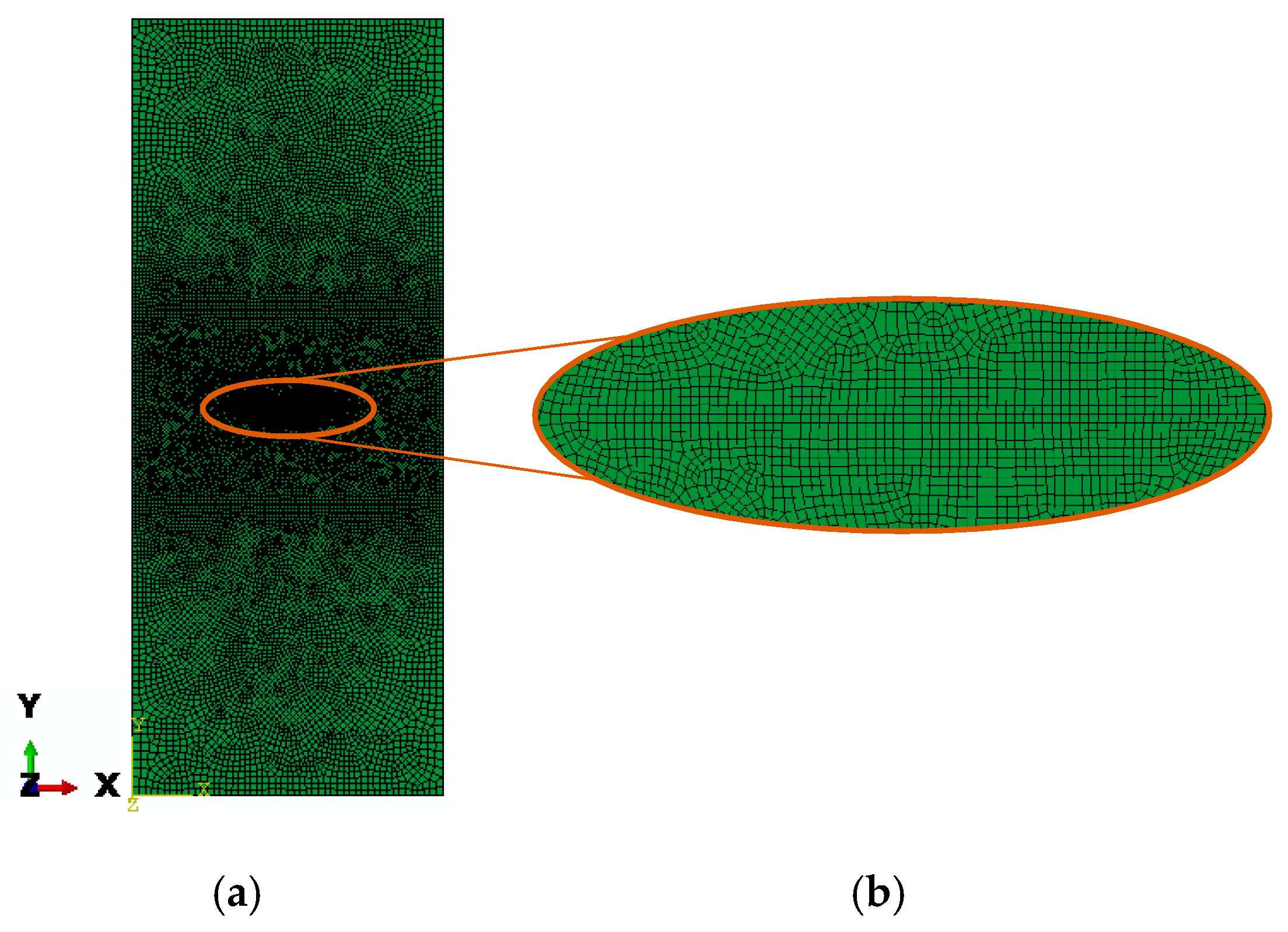
Based on von Karman’s linear theory, the total potential energy for an isotropic material with elastic behavior is written as follows [20]
Π = D h [ ω , xx 2 + ω , yy 2 2 ( 1 ν ) ( ω , xx   ω , yy ω , xy 2 ) + 2 ω , xx   ω , yy + h D ( σ x   ω , x 2 + 2 σ xy   ω , x   ω , y + σ y   ω , y 2 ) ] dxdy ,
where D is the bending stiffness of the sheet and equal to Eh 3 / 12 ( 1     ν 2 ) . E and ν are Young’s modulus and Poisson’s ratio, respectively. σ x , σ y and σ xy describe stresses during the pre-buckling state in plane, and ω is the sheet deflection. Critical buckling stress is assessed based on an eigenvalue problem through the minimization of the total potential energy. In Equation (1), the notations ( ) , ij indicates the partial derivatives with respect to the special coordinates i = x ,   y and j = x ,   y .
Defining the minimum positive eigenvalue, λ, the critical buckling stress for the sheet is calculated as follows
σ cr = λ E 6 ( 1     ν 2 ) ( h / a ) 2 ,
where the coefficient λ depends on Poisson’s ratio and the geometry and loading conditions of the sheet [25]. Equation (2) can be summarized by defining coefficient k and yields the following [17]
σ cr = kE ( h / a ) 2 ,
where k = λ / 6 ( 1     ν 2 ) depends on material and geometry properties.
In this study, it was assumed that there are many parameters that influence parameter k and critical buckling stress. The parameters studied in this research are Poisson’s ratio, yield stress, crack length-to-sheet width ratio and the sheet aspect ratio. Furthermore, it was assumed that thickness is sufficient to avoid strain localization, through thickness and also the fracture toughness is sufficiently high to prevent the sheet from failing from fracture. Therefore, the following is necessary
σ c   <   K Ic f π a   <   hE σ Y π a ( 1     ν 2 ) ,
where K Ic is the critical stress intensity factor, σ Y is the yield stress, and f is the geometrical parameter which in the current study is equal to 1.1 [28]. The two inequalities in Equation (4) mean that buckling occurs before start of crack growth in the cracked sheet (the first inequality from the left side) and the fracture toughness should be less than the energy release rate that leads to Dugdale necking type of failure.

3. Numerical Model

Finite element models using a commercial software [29] have been developed to study the buckling and post-buckling behavior of initially notched sheets under uni-axial tensile loading. Numerical simulation implements both material and geometrical nonlinearity. A perturbation analysis is used in this study while the post-buckling deformation is the primary concern.
The geometry of the thin notched sheet made of Al foil is listed in Table 1. At the lower-end boundary condition, displacement in y direction ( v = 0 ) and rotations in the x-y plane ( θ x ,   θ y   = 0 ) are constrained and displacement at the left corner closed against x direction movement ( u = 0 ). At the upper end, displacement in x direction and rotations in the plane are constrained ( u ,   θ x ,   θ y   = 0 ), but displacement in y direction is free to move ( v = v 0 ). Due to the small thickness of the sheet respect to its length/width dimension and according to Mindlin–Reissner flexural theory, the problem domain is discretized by four-node shell elements (S4R) with randomly distributed and fine meshes, visualized in Figure 2 considering three-dimensional quasi-static analyses. A fine mesh size was used around the cracked area for the accurate calculation of the deformation. The total number of elements are 20,816 and the smallest element size which is placed in the cracked zone is 0.2 mm.
Based on the classical Huber–Hencky–Mises yield criterion, an elastic and perfectly plastic constitutive law was assumed. The main parameters considered include Young’s modulus (E), equal to 46 GPa, and Poisson’s ratio (ν) of 0.3. Due to the importance of critical buckling stress and the evaluation of its effect on the plastic behavior of the sheet, the yield limit for plastic deformation was assumed to be 90% of the effective stress when buckling occurs in the simulations considering only elastic behavior.

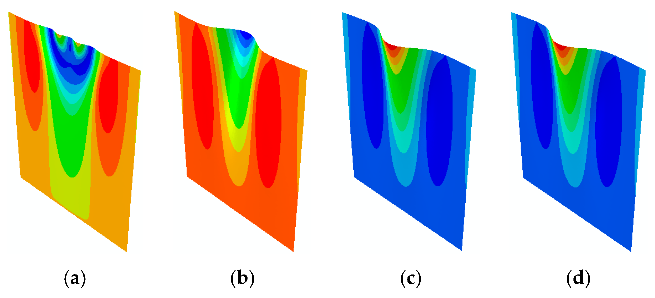
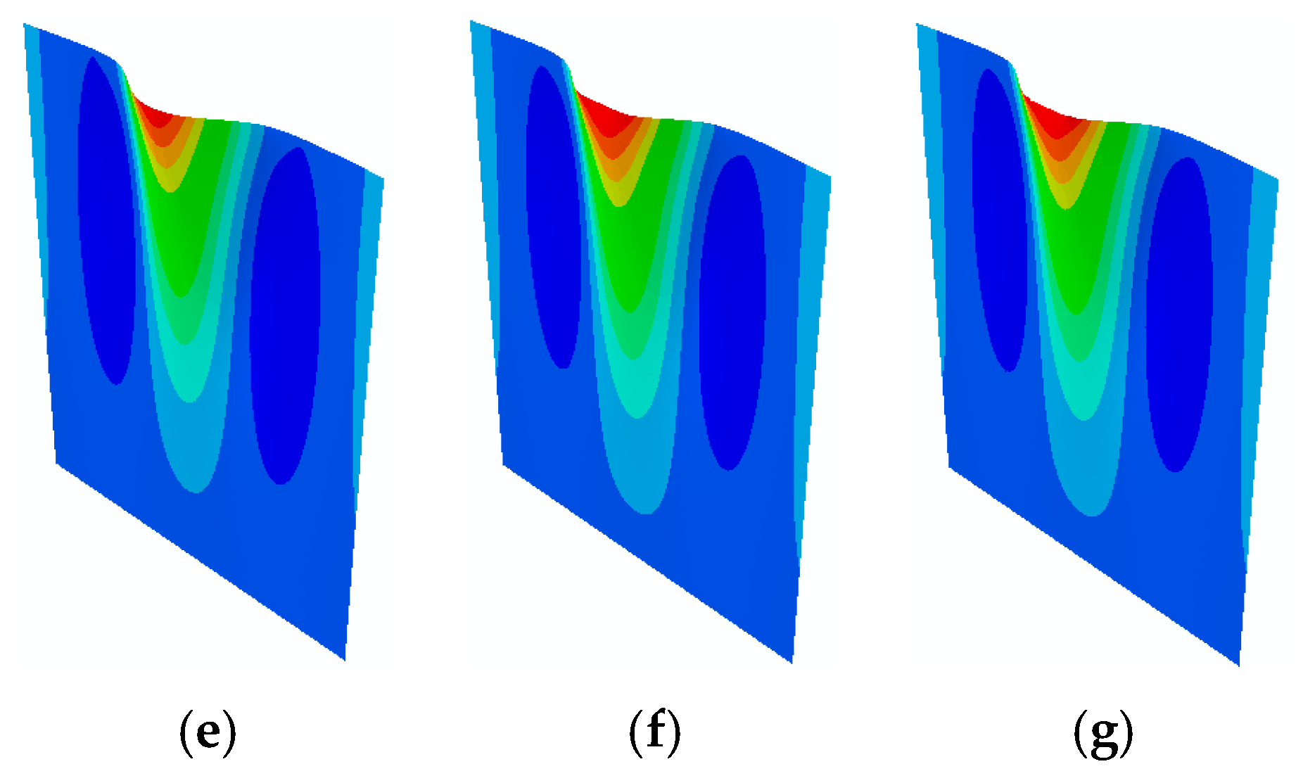
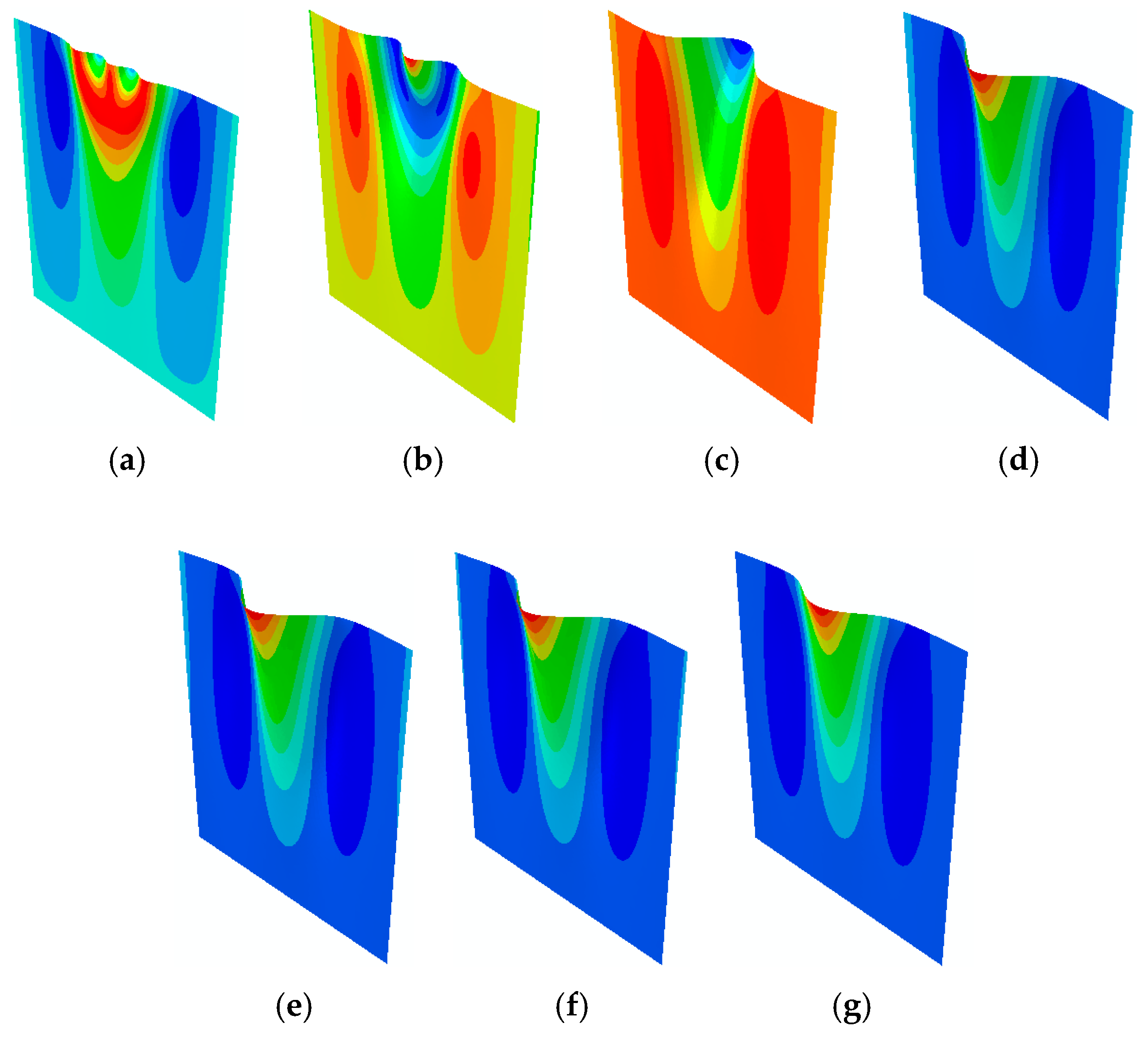
4. Results and Discussion

Different perturbation sizes were considered in numerical models as initial imperfections and for the purposes of stimulating buckling in the sheet. A perturbation is defined as a small bulge at the middle of a crack surface with a length of one quarter of the crack length. A perturbation size ranges from 0.01 µm to 1 mm in numerical models. Figure 3 displays non-dimensional buckling stress versus out-of-plane displacement at the middle of the crack, considering both elastic (Figure 3a) and elasto-plastic behavior (Figure 3b). Figure 3a reflects that critical buckling stress for the sheet with elastic behavior is roughly the same for perturbation sizes between 0.05 µm and 1 mm. The critical buckling stress increases significantly for a perturbation size of 0.01 µm.
Figure 3b depicts the buckling and post-buckling responses of the sheet, including elasto-plastic behavior. The critical buckling stress for 0.01 µm perturbation size is much higher compared to the others. In the thin sheet with central crack under tensile loading, the existence of compression stresses leads to appearance of wrinkles specifically in the cracked area. In the current study, the perturbations facilitate the occurrence of buckling and, as the perturbation sizes increase, they produce higher out-of-plane displacement around the cracked area, which results in a lower level of critical buckling stress, as represented in Figure 3 for both elastic and elasto-plastic cases. Applying elasto-plastic behavior changed the post-buckling trend compared to the only elastic material such that the curvature deviation reached a plateau. When out-of-plane displacement was increased, the buckling stress remained constant. This behavior is due to the consideration of perfectly plastic behavior in the plastic regime without any strain hardening.
For both elastic and elasto-plastic behavior, the critical buckling stress that is close to analytical and empirical relations occurs for perturbation sizes between 0.04 and 0.05 µm. We selected 0.045 µm. The critical buckling stress for the considered sheet was compared with the results obtained by recent researchers, listed in Table 2. The small discrepancy between this study’s results and those of others is due to the consideration of different geometrics and material properties, which can be attributed to k in relation to 3. Guz et al. [25] obtained the buckling stress from experiments using an extrapolation method from the already buckled state. The buckling load was around 20% lower than the present result. Their experiments were not described in detail, but even so, considering that experimental determination of the buckling load is rather complicated, we consider the results to support the current numerical results. In the experimental study done by Dyshel [26], the experimental tests supported the ( h / a ) 2 dependence of buckling stress. A limitation of their findings is that the results for infinite plates are used for all cracks covering up to half of the specimen width. In comparison, the stress intensity factor of the largest crack is 18% (cf. [28]) and possibly an underestimation of the load of that order of magnitude could be anticipated. Still, the results are believed to give confidence to the present result.
Figure 4 and Figure 5 demonstrate the distribution of the out-of-plane displacement in half of the sheets under tensile loading for both elastic and elasto-plastic material behavior, highlighting the dominant buckling mode shape. The different buckling modes of the sheet under tensile loading justify the increase in the critical buckling stress in the sheet with perturbation size of 0.01 µm for both elastic and elasto-plastic behavior for which the fifth buckling mode shape is dominant. For the other perturbation sizes, the buckling mode is the first one that requires less energy to be activated and is the reason for the lower critical buckling stress displayed in Figure 3.

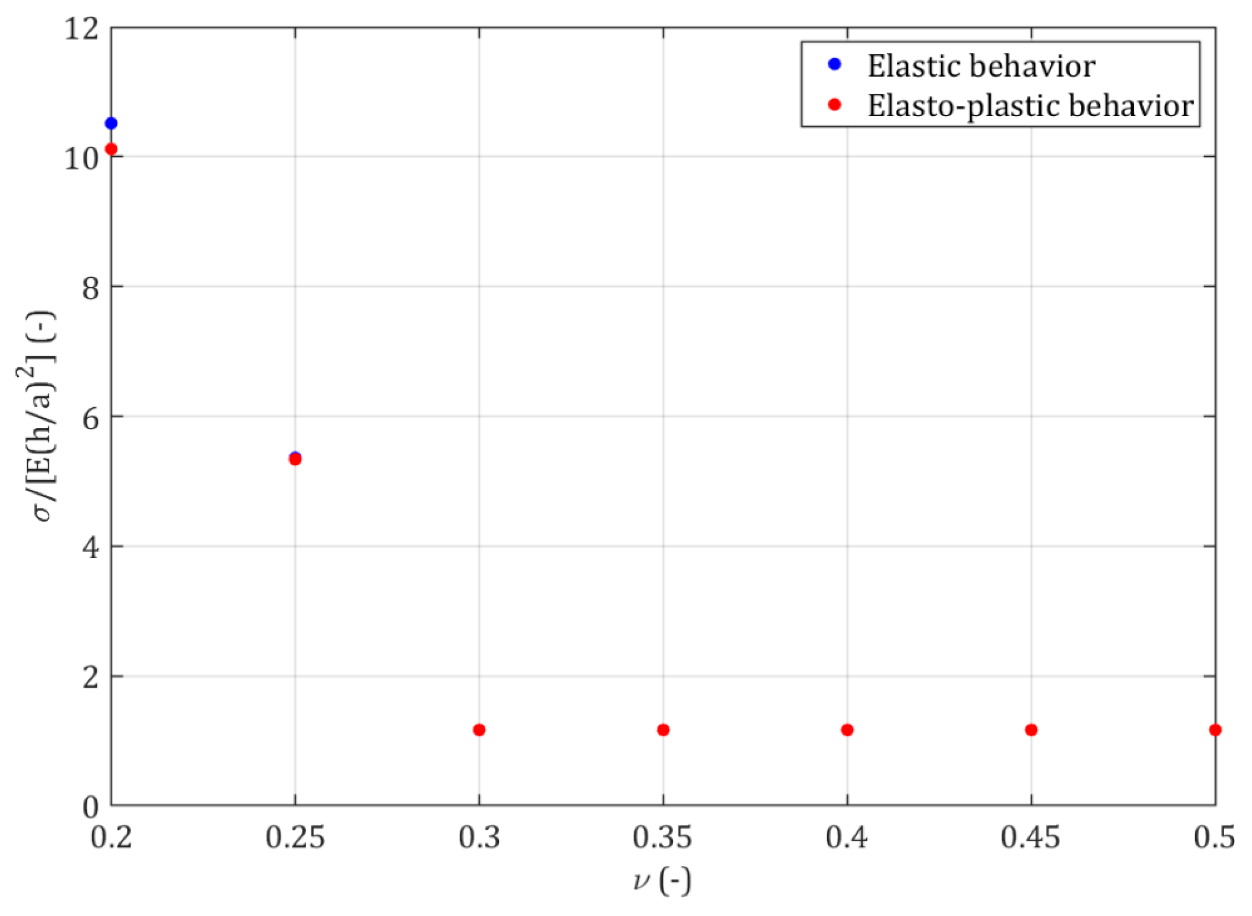
4.1. Influence of Poisson’s Ratio

In the numerical models, the influence of different Poisson’s ratios on non-dimensional critical buckling stress, with both elastic and elasto-plastic behavior, is studied. Poisson’s ratio has been changed in a range from 0.2 to 0.5 with 0.05 steps. Figure 6 visualizes the buckling and post-buckling behavior of the sheet with different Poisson’s ratios, considering both elastic (Figure 6a) and elasto-plastic (Figure 6b) behavior. In both cases, the maximum critical buckling stress occurs for the smallest Poisson’s ratio and reduces with the increase in Poisson’s ratio from 0.2 to 0.3. However, the critical buckling stress remains constant when Poisson’s ratio changes from 0.3 to 0.5. Poisson’s ratio has direct relation with lateral stresses, which, here, are compression stresses specifically around the cracked area. For small Poisson ratio’s, the lateral compression stresses are very low and then lead to a higher level of critical buckling stress.
The variation in critical buckling stress according to different Poisson’s ratios is displayed in Figure 7 for both elastic and elasto-plastic behavior. In both cases, the trend is the same, but the difference is in the level of critical buckling stress when Poisson’s ratios are small. In these scenarios, the critical buckling stress for elastic behavior is negligibly higher than for elasto-plastic behavior.
Figure 8 and Figure 9 demonstrate how different Poisson’s ratios change the buckling mode of the notched sheet for both elastic and elasto-plastic material behavior. These figures justify the increase in critical buckling stress in the sheet with Poisson’s ratio of 0.2 and 0.25, considering both elastic and elasto-plastic behavior. In Figure 8, the dominant buckling mode shape for Poisson’s ratios of 0.2, 0.25, and between 0.3 and 0.5 are the fifth, the third, and the first buckling mode shapes, respectively. For the elasto-plastic behavior displayed in Figure 9, the buckling mode shape changes according to different Poisson’s ratios. Although in both elastic and elasto-plastic cases, the critical buckling stress remains the same for Poisson’s ratios between 0.3 and 0.5, the buckling modes differ. This phenomenon highlights that the same critical buckling stress for different material behaviors does not lead to similar buckling mode shapes because the material behavior is also responsible for the activation of the buckling mode shape.

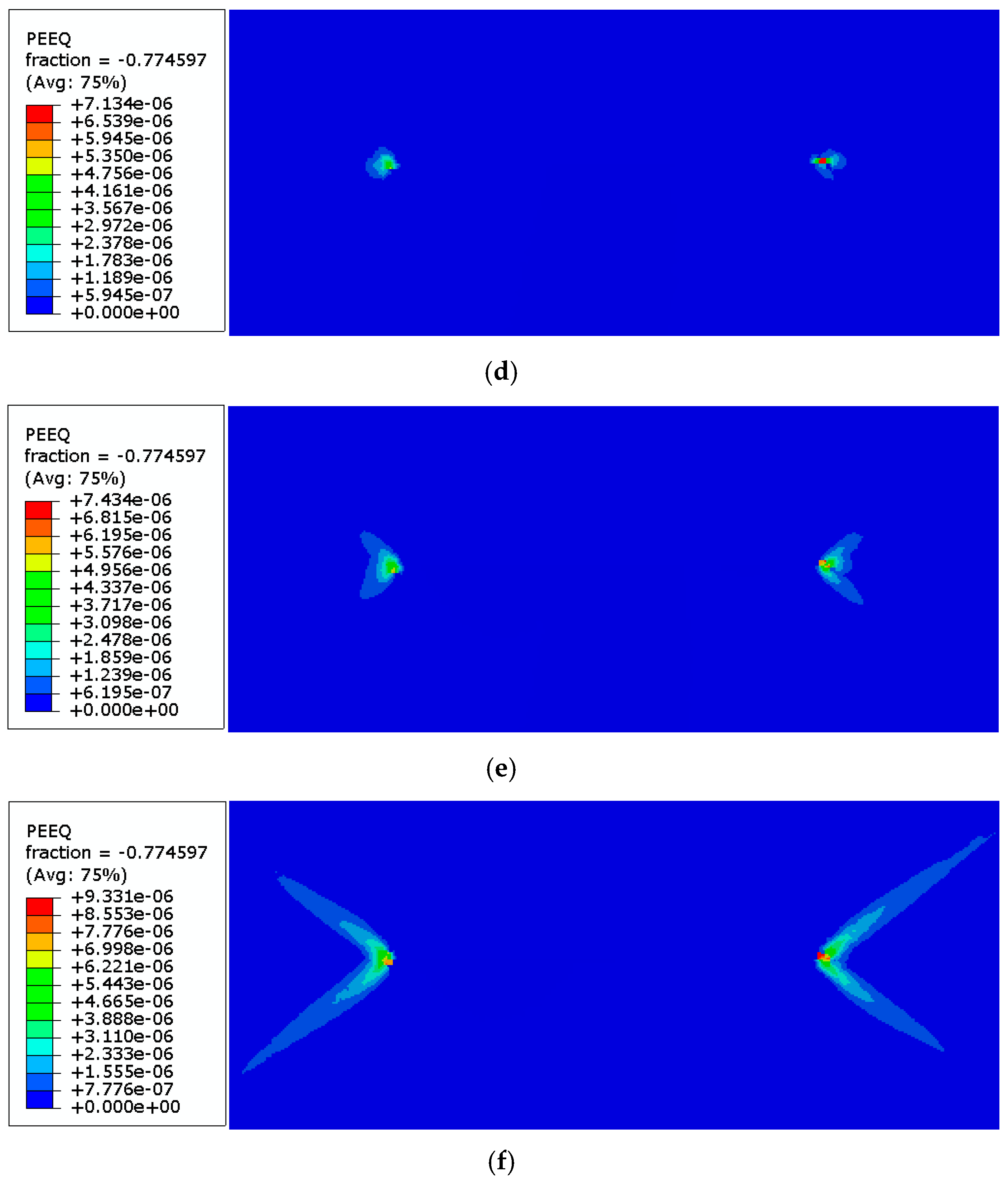
4.2. Influence of Yield Limit

In order to investigate how the yield limit influences critical buckling stress, different yield stresses were defined for the plastic deformation of the sheet assuming perfectly plastic behavior. It was assumed that yield stress is equal to effective stress when buckling occurs, and material behavior was defined only in the elastic regime ( σ eff ). The parameter m can be introduced as follows
m = ( σ cr el σ eff ) 1 5 ,
where σ cr el is the critical buckling stress, considering only elastic behavior. Various yield stresses are defined according to different ratios of m, such as, m 0 σ eff , m 1 σ eff , m 2 σ eff , m 3 σ eff , m 4 σ eff , and m 5 σ eff . It is worth noting that m is a value lower than 1 (m < 1).
Figure 10 depicts the effect of different ratios on the buckling stress of the notched sheet. One can see that a decrease in yield stress reduces critical buckling stress and changes the post-buckling behavior of the sheet such that, for the highest yield stress, first there is a curvature deviation and then a plateau. However, when yield stress decreases, the post-buckling behavior only shifts to a plateau. It is worth noting that different yield stresses do not change the buckling mode shape, and the first mode shape is dominant.
The distribution of the equivalent plastic strain around the crack tips when buckling occurs for different yield stresses is presented in Figure 11. To show the detailed distribution of the equivalent plastic strain, a close up of strain around the crack tips is represented. Although decreasing the yield stress reduces the critical buckling stress, the equivalent plastic strain around the crack tips increases. As displayed in Figure 11f, the lower yield stresses lead the equivalent plastic strain to form shear bands around the crack tips when buckling occurs.

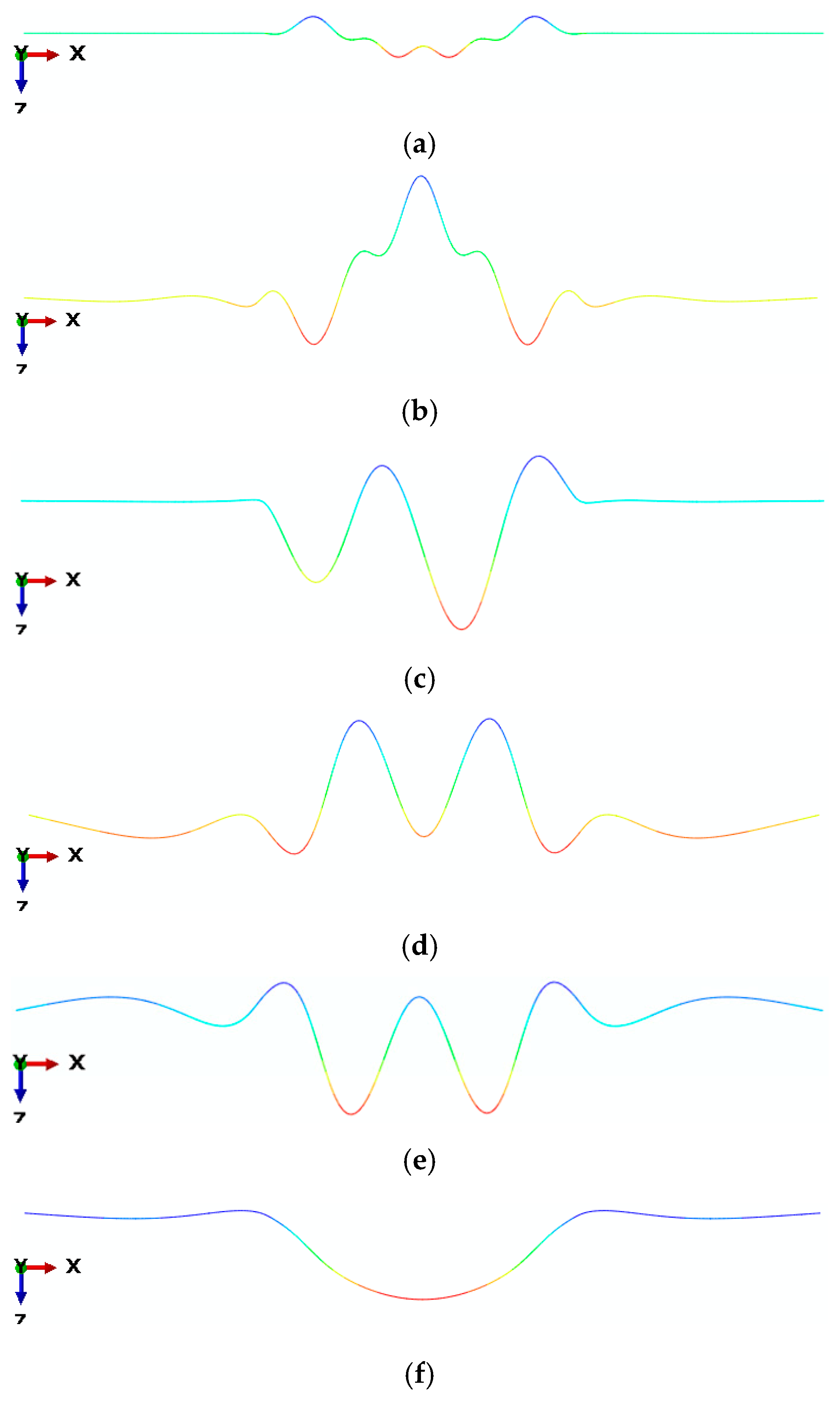
4.3. Influence of Crack Length-to-Sheet Width

The effect of crack length-to-sheet width ratio (2a/w) on the buckling behavior of the sheet considering both elastic and elasto-plastic behavior, is visualized in Figure 12. With an increase in 2a/w ratio, the critical buckling stress decreases (the non-dimensional critical buckling stress increases due to change in the crack length) and the post-buckling behavior changes. The definition of plasticity in the models does not change the critical buckling stress. By increasing the crack length-to-sheet width ratio, the compression stresses zone around the crack, which are responsible for the wrinkles and buckling behavior, increase, and then result in lower levels of critical buckling stress.
The buckling mode shapes of the sheet along the crack line with different crack length-to-sheet width ratios are depicted in Figure 13 and Figure 14 for both elastic and elasto-plastic material models. The buckling mode shapes for two material models are the same, but changes in 2a/w ratios make different mode shapes. The reason for the increase in the critical buckling stress with higher 2a/w ratios (except for 2a/w = 0.6) in Figure 12 is due to the activation of higher mode shapes. As is displayed in Figure 12, critical buckling stress for 2a/w = 0.5 is higher than 2a/w = 0.6 because of the dominant buckling mode shape presented in Figure 13e,f.

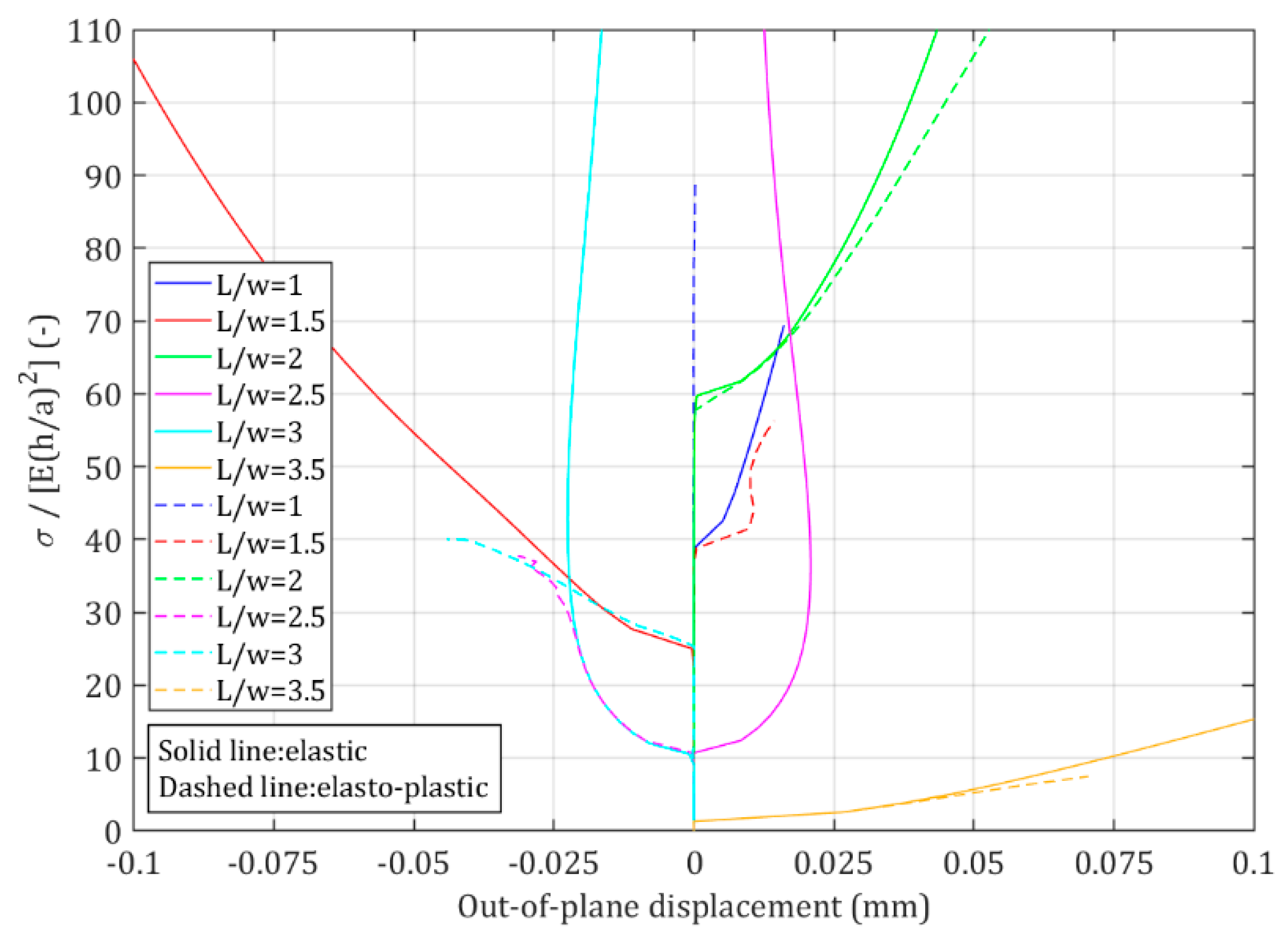
4.4. Influence of the Sheet Aspect Ratio

Figure 15 displays the influence of the sheet aspect ratio (L/w) on the buckling behavior of the sheet considering both elastic and elasto-plastic behavior. The buckling mode shape of the sheet along the crack line with different L/w is depicted in Figure 16 and Figure 17 for both elastic and elasto-plastic material models, respectively.
As is depicted in Figure 16 and Figure 17, an increase in the sheet aspect ratio does not lead a regular trend due to the activation of different mode shapes. It was expected that critical buckling stress would reduce with an increase in the sheet aspect ratio, but in Figure 15, for example, in the case of elasto-plastic behavior, the critical buckling stress for L/w = 2 is higher than it is for L/w = 1. The reason for this difference is their dominant buckling mode shape.

5. Conclusions

This research presented a numerical study on the buckling behavior of thin sheet under tensile loading. Different perturbation sizes were defined on the small part of the crack to stimulate buckling in the notched sheet. Then, the influence of different parameters, including perturbation size, Poisson’s ratio, yield limit, crack length-to-sheet width and sheet aspect ratios, on the critical buckling stress and the sheet buckling mode, was evaluated.
The numerical results demonstrated that quite small perturbations need more energy to trigger buckling in the sheet and activate higher buckling modes. Defining plasticity changes post-buckling behavior such that for higher displacements, the buckling stress remains constant, reaching a plateau, due to the consideration of perfectly plastic behavior without any hardening during plastic deformation.
With regard to different Poisson’s ratios, there is a threshold at which the critical buckling stress no longer changes. Low Poisson’s ratios activate higher buckling mode shapes, while the first buckling mode is dominant for the higher Poisson’s ratios.
Different yield limits were defined in the numerical model as some ratios of the effective stress when buckling occurs, and the results represented that decreases in the yield stress for the plastic behavior of the sheet reduce the critical buckling stress, increase the equivalent plastic strain when buckling occurs, and do not change the buckling mode. As the yield limits decreased, the post buckling behavior also altered such that the curvature deviation (wine-glass–shape curve) shortened to a plateau.
Different crack length-to-sheet width ratio (2a/w) has been varied in a range from 0.1 to 0.6. Increase of this ratio changed the post-buckling behavior of the sheet significantly and led to higher non-dimensional critical buckling stress, except for 2a/w = 0.6 for both elastic and elasto-plastic behavior, which was due to the activation of a lower buckling mode compared to 2a/w = 0.5. Different crack length-to-sheet width ratios and sheet aspect ratios could activate various buckling modes.
Among the considered parameters, the sheet aspect ratio and crack length-to-sheet width ratio have a more significant influence compared to others, especially with regard to their effect on critical buckling stress and buckling mode shape.

Author Contributions

Conceptualization, M.S., P.S. and S.K.-W.; methodology, M.S. and P.S.; software, M.S. and M.S.I.; formal analysis, M.S., P.S. and M.S.I.; investigation, M.S. and P.S.; writing—original draft preparation, M.S.; writing—review and editing, M.S., P.S., M.S.I. and S.K.-W.; visualization, M.S.; supervision, P.S. and S.K.-W. All authors have read and agreed to the published version of the manuscript.

Funding

Some of this work is included in a research activity of the Model Driven Development and Decision Support project (MD3S+) at Blekinge Institute of Technology, which is funded by the Swedish Knowledge and Competence Development Foundation (KKS).

Acknowledgments

The Authors would like to thank Eskil Andreasson for his valuable contributions.

Conflicts of Interest

The authors declare no conflict of interest.

References

  1. Bolzon, G.; Shahmardani, M.; Liu, R.; Zappa, E. Failure analysis of thin metal foils. Frat. Integr. Strutt. 2017, 11, 328–336. [Google Scholar] [CrossRef] [Green Version]
  2. Puntel, E.; Deseri, L.; Fried, E. Wrinkling of a stretched thin sheet. J. Elast. 2011, 105, 137–170. [Google Scholar] [CrossRef]
  3. Kao-Walter, S. On the Fracture of Thin Laminates. Ph.D. Thesis, Series No. 2004:07. Dep. Mech. Eng., Blekinge Institute of Technology, Karlskrona, Sweden, 2004. [Google Scholar]
  4. Fu, C.; Wang, T.; Xu, F.; Huo, Y.; Potier-Ferry, M. A modeling and resolution framework for wrinkling in hyperelastic sheets at finite membrane strain. J. Mech. Phys. Solids 2019, 124, 446–470. [Google Scholar] [CrossRef]
  5. Kim, T.-Y.; Puntel, E.; Fried, E. Numerical study of the wrinkling of a stretched thin sheet. Int. J. Solids Struct. 2012, 49, 771–782. [Google Scholar] [CrossRef] [Green Version]
  6. Bolzon, G.; Shahmardani, M.; Liu, R.; Zappa, E. A combined experimental-numerical investigation of the failure mode of thin metal foils. Procedia Struct. Integr. 2017, 3, 168–171. [Google Scholar] [CrossRef]
  7. Bolzon, G.; Shahmardani, M. Numerical simulation of non-standard tensile tests of thin metal foils. AIP Conf. Proc. 2018, 1922, 080011. [Google Scholar]
  8. Najarzadeh, L.; Movahedian, B.; Azhari, M. Stability analysis of the thin plates with arbitrary shapes subjected to non-uniform stress fields using boundary element and radial integration methods. Eng. Anal. Bound. Elem. 2018, 87, 111–121. [Google Scholar] [CrossRef]
  9. Nguyen-Thoi, T.; Bui-Xuan, T.; Phung-Van, P.; Nguyen-Xuan, H.; Ngo-Thanh, P. Static, free vibration and buckling analyses of stiffened plates by CS-FEM-DSG3 using triangular elements. Comp. Struct. 2013, 125, 100–113. [Google Scholar] [CrossRef]
  10. Mo, J.; Cheung, P.T.; Sherman, C.P.; Das, R. Chapter 11 - Thin Plate Deflection. Demystifying Numer. Models 2019, 235–255. [Google Scholar]
  11. Bolzon, G.; Shahmardani, M. Macroscopic response and decohesion models of metal-polymer laminates. Eng. Trans. 2017, 65, 53–59. [Google Scholar]
  12. Andreasson, E.; Kao-Walter, S.; Ståhle, P. Micro-mechanisms of a laminated packaging material during fracture. Eng. Frac. Mech. 2014, 127, 313–326. [Google Scholar] [CrossRef]
  13. Davidovitch, B.; Schroll, R.D.; Vella, D.; Adda-Bedia, M.; Cerdad, E.A. Prototypical model for tensional wrinkling in thin sheets. PNAS 2011, 108, 18227–18232. [Google Scholar] [CrossRef] [PubMed] [Green Version]
  14. Valente de Carvalho, R. Wrinkling of Thin Sheets under Tension. Master’s Thesis, Técnico Lisboa, Lisbon, Portugal, November 2015. [Google Scholar]
  15. Datta, P.K.; Biswas, S. Research advances on tension buckling behaviour of aerospace structures: A review. Int. J. Aeronaut. Space. 2011, 12, 1–15. [Google Scholar] [CrossRef] [Green Version]
  16. Markstrӧm, K.; Stoåkers, B. Buckling of cracked members under tension. Int. J. Solids Struct. 1980, 16, 217–229. [Google Scholar] [CrossRef]
  17. Shaw, D.; Huang, Y.H. Buckling behavior of a central cracked thin plate under tension. Eng. Frac. Mech. 1990, 35, 1019–1027. [Google Scholar] [CrossRef]
  18. Riks, E.; Rankin, C.C.; Brogan, F.A. The buckling behavior of a central crack in a plate under tension. Eng. Frac. Mech. 1992, 43, 529–548. [Google Scholar] [CrossRef] [Green Version]
  19. Brighenti, R. Buckling of cracked thin-plates under tension or compression. Thin Walled Struct. 2005, 43, 209–224. [Google Scholar] [CrossRef]
  20. Seif, A.E.; Kabir, M.Z. An efficient analytical model to evaluate the first two local buckling modes of finite cracked plate under tension. Lat. Am. J. Solids Struct. 2015, 12, 2078–2093. [Google Scholar] [CrossRef] [Green Version]
  21. Rammerstorfer, F.G. Buckling of elastic structures under tensile loads. Acta Mech. 2018, 229, 881–900. [Google Scholar] [CrossRef] [Green Version]
  22. Amiri Rad, A.; Panahandeh-Shahraki, D. Buckling of cracked functionally graded plates under tension. Thin Walled Struct. 2014, 84, 26–33. [Google Scholar] [CrossRef]
  23. Wang, T.; Fu, C.; Xu, F.; Huo, Y.; Potier-Ferry, M. On the wrinkling and restabilization of highly stretched sheets. Int. J. Eng. Sci. 2019, 136, 1–16. [Google Scholar] [CrossRef]
  24. Brighenti, R. Buckling sensitivity analysis of cracked thin plates under membrane tension or compression loading. Nucl. Eng. Des. 2009, 239, 965–980. [Google Scholar] [CrossRef]
  25. Guz, A.N.; Dyshel’, M.S.; Nazarenko, V.M. Fracture and stability of materials and structural members with cracks: Approaches and results. Int. Appl. Mech. 2004, 40, 1323–1359. [Google Scholar] [CrossRef]
  26. Dyshel, M.S. Stability and fracture of plates with a central and an edge crack under tension. Int. Appl. Mech. 2002, 38, 472–476. [Google Scholar] [CrossRef]
  27. Ståhle, P.; Li, C.; Bjerkén, C. Crack tip singularity in a buckling thin sheet. In Proceedings of the 19th Nordic Seminar on Computational Mechanics, Lund, Sweden, 20–21 October 2006; pp. 43–46. [Google Scholar]
  28. Isida, M. Effect of Width and Length on Stress Intensity Factors of Internally Cracked Plates Under Various Boundary Conditions. Int. J. Fract. 1971, 7, 301–316. [Google Scholar] [CrossRef]
  29. HKS Inc. ABAQUS/Standard, Theory and User’s Manuals, Version 2019; HKS Inc.: Pawtucket, RI, USA, 2019. [Google Scholar]
Figure 1. A thin sheet with a central crack under tension.
Metals 10 00582 g001
Figure 2. Mesh discretization (a) for the whole sheet with a central crack and (b) around the crack.
Metals 10 00582 g002
Figure 3. Non-dimensional buckling stress versus out-of-plane displacement for the sheet with (a) elastic behavior and (b) elasto-plastic behavior with different perturbation sizes.
Metals 10 00582 g003
Figure 4. Distribution of out-of-plane displacements in half of the sheet, considering only elastic behavior, and with perturbation sizes of (a) 0.01 µm, (b) 0.05 µm, (c) 0.1 µm, (d) 1 µm, (e) 0.01 mm, (f) 0.1 mm, (g) 1 mm.
Metals 10 00582 g004aMetals 10 00582 g004b
Figure 5. Distribution of out-of-plane displacements in half of the sheet, considering elasto-plastic behavior and with perturbation sizes of (a) 0.01 µm, (b) 0.05 µm, (c) 0.1 µm, (d) 1 µm, (e) 0.01 mm, (f) 0.1 mm, (g) 1 mm.
Metals 10 00582 g005
Figure 6. Non-dimensional buckling stress versus out-of-plane displacement for the sheet with (a) elastic behavior and (b) elasto-plastic behavior with different Poisson’s ratios.
Metals 10 00582 g006
Figure 7. Changes in critical buckling stress according to different Poisson’s ratios.
Metals 10 00582 g007
Figure 8. Distribution of out-of-plane displacements in half of the sheet, considering only elastic behavior, and with Poisson’s ratios of (a) 0.2, (b) 0.25, (c) 0.3, (d) 0.35, (e) 0.4, (f) 0.45, and (g) 0.5.
Metals 10 00582 g008
Figure 9. Distribution of out-of-plane displacements in half of the sheet, considering elasto-plastic behavior, and with Poisson’s ratios of (a) 0.2, (b) 0.25, (c) 0.3, (d) 0.35, (e) 0.4, (f) 0.45, and (g) 0.5.
Metals 10 00582 g009
Figure 10. Non-dimensional buckling stress versus out-of-plane displacement for the sheet with different yield stresses.
Metals 10 00582 g010
Figure 11. Distribution of equivalent plastic strain with different yield stresses (a) σ eff , (b) m 1 σ eff , (c) m 2 σ eff , (d) m 3 σ eff , (e) m 4 σ eff and (f) m 5 σ eff .
Metals 10 00582 g011aMetals 10 00582 g011b
Figure 12. Non-dimensional buckling stress versus out-of-plane displacement for the sheet with different crack length-to-sheet width ratios.
Metals 10 00582 g012
Figure 13. Buckling mode shape of the sheet along the crack line, considering elastic behavior and with 2 a / w of (a) 0.1, (b) 0.2, (c) 0.3, (d) 0.4, (e) 0.5, and (f) 0.6.
Metals 10 00582 g013
Figure 14. Buckling mode shape of the sheet along the crack line considering elasto-plastic behavior and with 2 a / w of (a) 0.1, (b) 0.2, (c) 0.3, (d) 0.4, (e) 0.5, and (f) 0.6.
Metals 10 00582 g014
Figure 15. Non-dimensional buckling stress versus out-of-plane displacement for the sheet with different aspect ratios.
Metals 10 00582 g015
Figure 16. Buckling mode shape of the sheet along the crack line considering elastic behavior and with L / w of (a) 0.1, (b) 0.15, (c) 0.2, (d) 0.25, (e) 0.3, and (f) 0.35.
Metals 10 00582 g016
Figure 17. Buckling mode shape of the sheet along the crack line, considering elasto-plastic behavior and with L / w of (a) 0.1, (b) 0.15, (c) 0.2, (d) 0.25, (e) 0.3, and and (f) 0.35.
Metals 10 00582 g017
Table 1. Geometry details of the sheet.
Length (L, mm)Width (W, mm)Thickness (h, mm)Crack Length (2a, mm)
2501000.00940
Table 2. Comparison between critical buckling stress of the current study and the others.
Researchers σ c r (MPa)
Current study0.01282
[25]0.0094
[26]0.01118
[17]0.0104

