Article

An Infrared Local-Heat-Assisted Cold Stamping Process for Martensitic Steel and Application to an Auto Part

1
School of Mechanical Engineering, Sungkyunkwan University, Suwon 16419, Gyeonggi-do, Korea
2
Department of Smart Fab. Technology, Sungkyunkwan University, Suwon 16419, Gyeonggi-do, Korea
3
Industrial Tools Technology Department, Ewha Diamond Co., Osan 18145, Gyeonggi-do, Korea
4
Process & Engineering Research Labs. POSCO, Pohang 37859, Korea
5
Steel Solution Research Labs. POSCO, Incheon 21985, Korea
*
Author to whom correspondence should be addressed.
Metals 2020, 10(11), 1543; https://doi.org/10.3390/met10111543
Submission received: 23 October 2020 / Revised: 14 November 2020 / Accepted: 17 November 2020 / Published: 20 November 2020
(This article belongs to the Special Issue Combinatorial Investigations of Alloys)

Abstract

:
The automotive industry has tried to employ ultra-high-strength steel (UHSS), which has a higher strength with a thinner thickness. However, because of its low formability, there is a limit to the use of UHSS in industrial applications. Even though the hot-press-forming method can resolve the formability problem, elevated-temperature conditions lead to side effects—heat transfer and productivity issues. This work presents the concept of an infrared local-heat-assisted cold stamping process. Before the forming process, local areas, where the formability problem occurs, are locally heated by the gathering of infrared rays and cooled to room temperature before delivery. Since the heat treatment is completed by the material supplier, the stamping companies can conduct cold stamping without new investments or the productivity issue. In this work, a heat-assisted cold V-bending test was conducted with a martensitic (MS) 1.5 GPa steel, the CR1470M steel provided by POSCO. The heating effects on the microstructure, hardness, and local ductility were also observed. Finally, a commercial door impact beam was successfully manufactured with the present method. In this application, only a targeted small area was heated. The results show that the present method can improve the formability and springback problems of MS steel in the stamping process.

1. Introduction

In order to meet the requirement of reducing the weight of the car body, steel companies have developed ultra-high-strength steels (UHSSs) that have a higher strength with a thinner thickness. However, the formability problem has been an obstacle to the application of the UHSSs. In order to improve the formability, some studies have introduced heating methods [1,2,3]. One of the widely used methods is hot press forming [4,5,6,7,8]. Hot press forming can manufacture auto parts having about a 1.5 GPa strength without factures or springback. However, this method requires quenching time to make the martensite microstructure, and also, austenitization is needed, which requires maintaining a high-temperature condition during the heating process, resulting in high energy consumption [9]. In parallel with hot press forming, some researchers have studied heating methods without the quenching process. Mohammad and Mahdi [10] conducted warm forming with Dual-Phase (DP) 600 sheets, and Park et al. [11] introduced an incremental induction heating method for DP600 sheets. Zheng et al. [12] performed some experiments on the hot deep drawing of aluminum alloys. Shao et al. [13] introduced direct flame impingement heating for hard-to-form materials. Previous studies have brought forward good solutions to resolve the formability problem under elevated-temperature conditions. However, the elevated-temperature conditions have brought undesired side effects—a heat transfer issue for the forming tools and decrease in the productivity of the forming process [14,15,16,17].
This paper presents a local heat-assisted cold stamping process for martensitic (MS) steel. Since MS steel has a high volume fraction of martensite, this material has a very high strength but low formability. Because of the low formability, applications of MS steel are based on roll-forming processes, and it is not easy to apply MS steel to stamping processes. The purpose of this work was to apply MS steel to a press-forming process with the heat-assisted cold stamping process because press-forming processes are efficient for making complex shapes for industrial applications. In heat-assisted cold forming, heat treatment is completed before the forming process. The heat-treatment process can be completed by steel companies before delivery to forming companies in order to resolve the die cooling and productivity problems. In the heat treatment, the local areas of a material, where the formability problem occurs, are locally heated and then cooled to room temperature. This heat treatment causes a change in microstructure resulting in a decrease in yield stress and increase in elongation. In addition, the local ductility changes caused by the heat treatment are discussed in this paper because the elongation of UHSS is not directly related to the local ductility for bending on a tight radius, especially for materials having ultimate tensile strength (UTS) values above 800 MPa [18]. The local ductility is measured by the true thickness change or fracture toughness. After delivering the heat-treated material to forming companies, the forming companies can conduct cold stamping; the paper calls this process a heat-assisted cold stamping process. The target material was an MS 1.5 GPa steel, the CR1470M steel supplied by POSCO. The heat source for the local heat treatment was an infrared (IR) heater that achieves a high energy efficiency by gathering IR rays on a narrow area [19,20]. Since only limited areas exhibit formability problems, IR local heat treatment can reduce the heating energy and avoid undesired heat-affected zones [21]. A heat-assisted cold V-bending test was conducted to study the performance of the heat-assisted cold forming. The heating effects on the microstructure and hardness were also observed in order to find an appropriate heat-treatment-temperature condition. The local formability was also measured. Finally, a door impact beam was successfully manufactured by using the heat-treatment, and the mechanical performance of the door impact beam was tested with a three-point bending experiment. The results of this work show that heat-assisted cold forming can be applied to real auto part press forming for MS steel with reduced heating energy.

2. Heat-Assisted Cold Stamping and V-Bending Experiment

Figure 1 shows the concept of heat-assisted cold stamping for V-bending. Heat-assisted cold forming separates the heat-treatment and forming processes. Since the V-bending has the plastic deformation zone in the center of the sheet, the IR heater only heated the center of the sheet, by gathering IR rays on the heated area, as shown in Figure 1, and then the material was cooled to room temperature. In the application of mass production, this heat treatment could be conducted by steel companies before delivery to forming companies.
This heat treatment leads to microstructural change as well as a change in mechanical properties. This heating effect on the microstructure is discussed in the discussion section. After the heat-treatment process, the material is delivered to forming tools to form the target material. Since the forming process is conducted at room temperature, a cooling system is not required in the forming tools. An MS 1.5 GPa steel (CR1470M steel) with a 1.5 mm thickness was employed in this work, and the properties are summarized in Table 1; the material is supplied by POSCO, and the properties were also obtained from the supplier. Note that this material is in a research state and has not yet been commercialized.
Before the forming test, a test of the local heat treatment was conducted in order to confirm the local heating effect, as shown in Figure 2. The IR heater (Sung San Tech., Republic of Korea) heated the test specimen with 1 kW of power. The dimensions of the specimen were 180 × 20 × 1.5 mm. The principle of the IR heater gathering IR rays on the heating area is presented in previous studies [22,23]. In order to measure the temperature, K-type thermocouples were used, and 10 positions (0, 5, 10, 15, 20, 25, 30, 40, 50, and 60 mm) were selected to measure the temperature distribution. Note that 0 mm is the center of the heated area. To avoid the direct heating of the thermocouple, small holes were made on the side of the sheet at each measurement position, and the thermocouples were inserted in the holes.
The heating was conducted until the central temperature reached 800 °C, and then, the material was cooled in the air. Figure 3a shows the effects of the heating and cooling rate at each position, and Figure 3b represents the temperature distribution of each temperature condition (the central temperatures are 200, 400, 600 and 800 °C).
The heat-treatment results show that the IR heater can induce the local heating of the heated area. Based on the heat-treatment results, a V-bending test was conducted. The heat-treatment temperature conditions for the V-bending test were 25 °C (no heat treatment), 200 °C, 400 °C, 600 °C, and 800 °C. Note that the temperature values are the central temperature values, and after reaching the target temperature, the heater was removed to cool the specimen without maintaining the temperature; the cooling was air-cooling in this test. The V-bending test was then conducted at room temperature. Figure 4 presents the experimental setting of the V-bending. For the V-bending test, the punch speed was 5 mm/s, the target angle was 90°, and the radius of the punch was 2 mm.

3. Results

Figure 5a represents the specimen of the no-heat-treatment condition after the V-bending. A crack occurred on the outer surface of the bending zone because of the low formability of the MS steel, as shown in Figure 5a. The 200 °C-heat-treated specimen was not able to avoid the crack problem. The same crack occurred on the specimen of the 200 °C condition; the result is almost the same as that for the no-heat-treatment condition shown in Figure 5a. The 400 °C-heat-treatment condition was able to prevent the crack, but springback was another issue under the 400 °C condition. The bent angle of the 400 °C-treated specimen was 100° (10° springback). The higher temperature of the 600 °C condition was able to reduce the springback problem. The 600 °C condition led to 92° for the bent angle. These results show that heat-assisted cold forming in 400 and 600 °C conditions can resolve both the formability and springback problems, and the results from the 400 and 600 °C conditions are shown in Figure 5b. In the 800 °C condition, the trend was reversed such that the crack was generated again on the bending zone, as shown in Figure 5c. These results reveal that the temperature condition is very important, and the results are summarized in Table 2. The heat-treatment condition is discussed in the next section.

4. Discussion

In order to explore the heating effect, the hardness was measured according to the heat-treatment temperature. Hardness is an important indicator for checking the heating effect; a decreasing hardness usually denotes a decrease in flow stress and increase in elongation. The Rockwell B (HRB) hardness was measured in the center of the local-heat-treated specimen (refer to Figure 2) for each temperature condition. The results are shown in Figure 6. The as-received material (non-heat-treated specimen) had 116.4 (HRB), and the 200 °C heat treatment led to 116.1 (HRB); the two conditions had almost the same hardness value. This result is related to the experimental results showing that the as-received material and 200 °C-heat-treated specimens had the same crack on the V-bending zone. The 400 °C condition caused a decrease in hardness, to 114.4 (HRB), and the 600 °C condition produced a lower hardness value, 112.3 (HRB). The 800 °C condition raised the hardness value again to the level of the as-received material, about 116 (HRB), meaning that the yield stress increased and the elongation decreased again. The decrease in yield stress led to a decrease in springback in the 600 °C condition. These hardness results can support the results of the V-bending test. The recovered hardness resulted in the crack again at 800 °C. In order to clearly explore the heating effect in the 600 and 800 °C conditions, a tensile test was conducted with the as-received material and the 600 °C-heat-treated and 800 °C-heat-treated materials. Note that in bending on a tight radius, the local ductility should additionally be considered because the elongation of UHSS is not directly related to the local ductility, especially for materials having UTS values over 800 MPa [18].
For the tensile test, the ASTM D638 specimens were made along the rolling direction, and the specimens were heated as shown on the right side of Figure 7. In the IR heat treatment, the whole specimen was covered to produce the same heating effect on the specimen. The SHIMAZU universal testing machine (UTM, SHIMAZU, Japan) with 100 kN was employed in the test, and the results are presented in Figure 7. The as-received material had the highest UTS, but the 600 °C-heat-treated specimen presented a drastically reduced strength. It was the cause of the reduced springback. The 800 °C-heat-treated specimen showed an increased strength compared to the 600 °C-heat-treated specimen. These results support the increased hardness in the 800 °C condition.
The 600 and 800 °C local-heat-treated sheets (shown in Figure 2) were taken to additionally measure the hardness change according to the position. Based on the center of the heating, the HRB hardness was measured at an interval of 3 mm, as shown in Figure 8a, and the hardness results are presented in Figure 8b. The hardness distribution from the 600 °C condition shows the local heating effect; the center had the lowest hardness, and hardness increased with the distance from the center since the heat-treated temperature decreased with the distance from the center. At the positions outside 20 mm, the hardness recovered to the level of the as-received material. On the other hand, in the 800 °C-heat-treated specimen, the hardness values were very high near the center, almost the same as the as-received material. At about the 9 mm position, which was heated to about 600 °C, the hardness value was the lowest, and positions outside 20 mm showed higher hardness values. The observation of the hardness distribution confirms the local heating effect. In addition, the hardness measurements after the 600 and 800 °C heat-treatment conditions imply that even though the 600 °C condition leads to a decomposition of martensite, 800 °C is able to reproduce the martensite structure in the CR1470M steel made by POSCO.
For a detailed investigation, the microstructures were observed at the same position of the hardness measurement (from 0 to 18 mm positions), with the 800 °C-heat-treated specimen, via a ×500 optical microscope (LEICA, Wetzlar, Germany). Figure 9 shows the results of the microstructure observation at each position. Figure 9a shows that the as-received material was mainly composed of martensite. The 6 mm (Figure 9d) to 12 mm (Figure 9f) positions show a decomposition of the martensite caused by heat treatment, and these results affected the decrease in hardness, as shown in Figure 8. At the 18 mm position (Figure 9h), the microstructure change was not significant because of the low-temperature condition in the thermal distribution, as shown in Figure 3b. At the positions from 0 mm (Figure 9b) to 3 mm (Figure 9c), where the temperature condition was close to 800 °C, the microstructure looks similar to the original material (Figure 9a). This could be the cause of the results of the hardness and tensile tests for the 800 °C-heat-treated specimen, as shown in Figure 6 and Figure 7. In order to understand these results, some reported studies are useful. In the industries of third-generation high-strength steels, manganese content has received a lot of attention from many studies [24,25,26,27,28]. Gramlich et al. [24] have recently shown that controlling the fraction of manganese in steel can lead to a nearly 100 vol% homogeneous martensitic microstructure even after air cooling from several heat treatments; the temperature conditions were close to the austenite transformation temperature (Ac3), about 800 °C in their work. The mechanical properties, after the air-hardening, also resembled those of martensite. They called this material an air-hardening martensitic steel. This steel has attracted attention from steel manufacturers because it could remove the quenching and tempering processes in the production plants, leading to the simple control of manufacturing. The martensitic steel used in this paper is similar to the material in the study of Gramlich et al. [24]. The material used in this paper is in a research state in POSCO, not yet commercialized. Thus, the details of the chemical composition are not available in this paper, but it is useful to refer to the tables in [24] for detailed information. This study of Gramlich et al. [24] can explain the results for the microstructures at the positions from 0 mm (Figure 9b) to 3 mm (Figure 9c) as well as the hardness recovery of the 800 °C-heat-treated specimen, as shown in Figure 6. Another study by Kuzmina et al. [25] reported the effect of the manganese content on embrittlement after heat treatments. They showed that, even after a short time of tempering above 600 °C, the manganese directly embattles the martensite grain boundaries. Moreover, it was observed that the manganese segregates to dislocations, which can cause an increase in hardness with a reduction in formability. Some other papers also present embrittlement caused by manganese in third-generation high-strength steels [29,30]. These results can support the results of the hardness and V-bending tests for the 800 °C-heat-treated specimens, as shown in Figure 5 and Figure 6.
However, the effects of the chemical composition of third-generation high-strength steels still need further study. In addition, even though the heat treatment of 800 °C in this paper is close to the Ac3 temperature of the material, the holding time may not be enough for obtaining homogeneous martensite. In this case, the 800 °C-heat-treated microstructure may not be homogeneous martensite. This could be another cause of the low local formability because fine and homogeneous microstructures have higher fracture resistance than microstructures having more than one constituent [31]. Moreover, since UHSS materials, having UTS values above 800 MPa, do not show a direct association between the global elongation and local formability [18], it is necessary to study the local formability change caused by the IR heat treatment. It is useful to define the formability index (FI) with the true uniform strain ( ε u ) and true fracture strain (TFS) from the tensile test specimens, as below [32,33]:
F I = ε u · T F S
ε u is defined in terms of the percent uniform elongation (UE) by
ε u = l n [ 1 + U E / 100 ]
and TFS can be defined in several ways to check the local formability. This work defines two TFSs with cross-sectional area and thickness changes after material failure in the tensile test in Figure 7. They are given by [32,33]
T F S a r e a = l n [ A 0 / A f ] ,   and   T F S t h i c k n e s s = l n [ t 0 / t f ] ,
where A0 and Af are cross-sections of the initial and after-fracture states, respectively. t0 and tf mean the effective thickness values of the initial and fracture states, respectively. In order to determine Af and tf, the projection of the fracture cross-section to the tensile axis is used, as shown in Figure 10a. Since the thickness differs according to the position in the width ( w f ) direction, tf and Af are calculated as below:
t f = 1 5 [ t a + t b + t c + t d + t e ] ,   and   A f = w f t f ,
where t a t e are the thickness values at each position, and w f is the width in Figure 10a. Figure 10b,c compare the uniform strain and local formability with T F S a r e a and T F S t h i c k n e s s , respectively. The curved auxiliary lines in the figures present the contours of the FI. In both comparisons, the as-received material and 800 °C-heat-treated specimen are close to having similar uniform strains and local formability. On the other hand, the 600 °C-heat-treated specimen presents clearly improved TFSs, as shown in Figure 10b,c, with higher FI values. Based on the results of this study (springback, hardness, microstructure, and local formability), 400~600 °C conditions are considered good heat-treatment conditions for improving the local formability and springback problem.

5. Application for Door Impact Beam

An auto part application was conducted with a door impact beam part. The employed forming tools were originally designed for a complex phase (CP) 1180 sheet. This door impact beam example is a reverse-engineered part of a mass-produced commercial product. The original process for the CP1180 sheet consisted of two stamping stages, OP10 and OP20. Figure 11a represents the modeling of the target door impact beam, and Figure 11b shows the original process (OP10 and OP20) with CP1180. The forming tools for the door impact beam were supplied by POSCO. The purpose of this work was to apply heat-assisted cold forming to the door impact beam. In this test, the MS 1.5 t blank was locally heat treated and then cooled. The heat-treated regions were selected where the formability issue occurred on the original CP1180 blank based on POSCO’s simulation with the Autoform R7 program (AutoForm Engineering, Zurich, Switzerland), as shown in Figure 12a. The heat-treated width for each region was about 100 mm. The heating process is shown in Figure 12b. The heat treatment was conducted until 600 °C for both the left and right sides. With the heat-treated blank, the OP20 forming was directly conducted without the OP10 process. In the forming test, a 1000-ton press was employed and the press speed was 20 mm/s. The press and die settings are shown in Figure 13a. Figure 13b shows the formed part after heat treatment, and the dark areas are the heat-treated areas. Figure 13c shows the formed part without the heat treatment. Only the heat-treatment condition was different, and the other conditions were the same. As shown in Figure 13b, the 600 °C heat treatment was able to avoid the fracture problem, while the lack of heat treatment resulted in a large fracture.
Finally, the mechanical performance of two door impact beams (with or without the heat treatment) was compared. In order to build the door impact beam without the heat treatment, specialized servo press control was enacted through two press processes, OP10 and OP20. Note that this control is not easy in mass production processes. Auto parts can be tested by a three-point bending test [34]. The setting of the three-point bending test in this work is shown in Figure 14a. Figure 14b presents the comparison of the load-displacement curves of the door impact beams. The two curves show very similar tendencies in the earlier stiffness, peak load, and failure position (150 mm of punch displacement). Since the local-heat-treated areas are close to both ends, the heat-treated areas have bending moments much lower than the bending moment of the center point. Thus, the heat-treated door impact beam shows almost the same performance compared to that of the non-heated part in three-point bending. The results of this paper show that heat-assisted cold forming can be applied to real auto parts.

6. Conclusions

This work represents a study on local-heat-assisted cold stamping. The target material was MS 1.5 GPa steel, and the heat source was an IR heater. The results are explained below in detail:
(1)
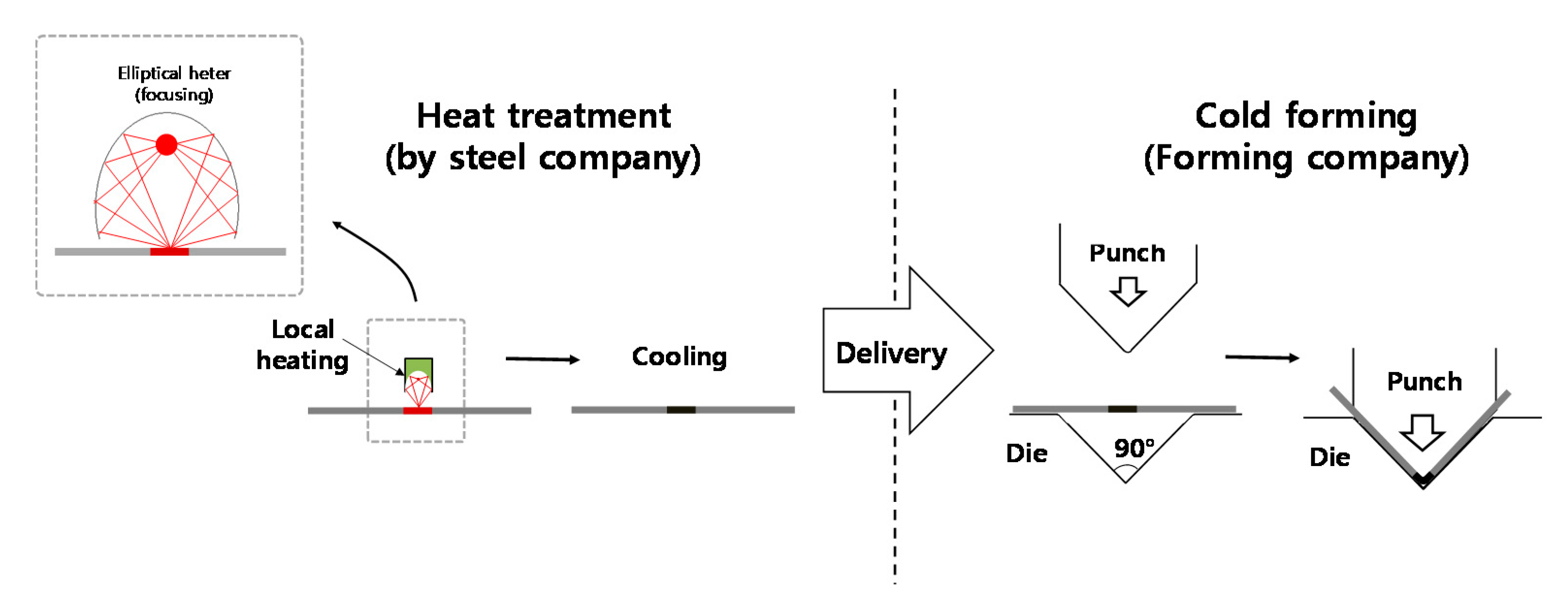
The heat-assisted cold stamping process separated the heat treatment and forming processes. The heat treatment could be conducted by steel companies before delivery to forming companies. The forming companies could conduct the cold forming. Since this method completes the heat treatment with material supplies, the stamping companies could conduct cold stamping without new investments for heating devices. This method can avoid the difficulty of hot forming under elevated-temperature conditions—a cooling problem for forming tools and a decrease in productivity.
(2)
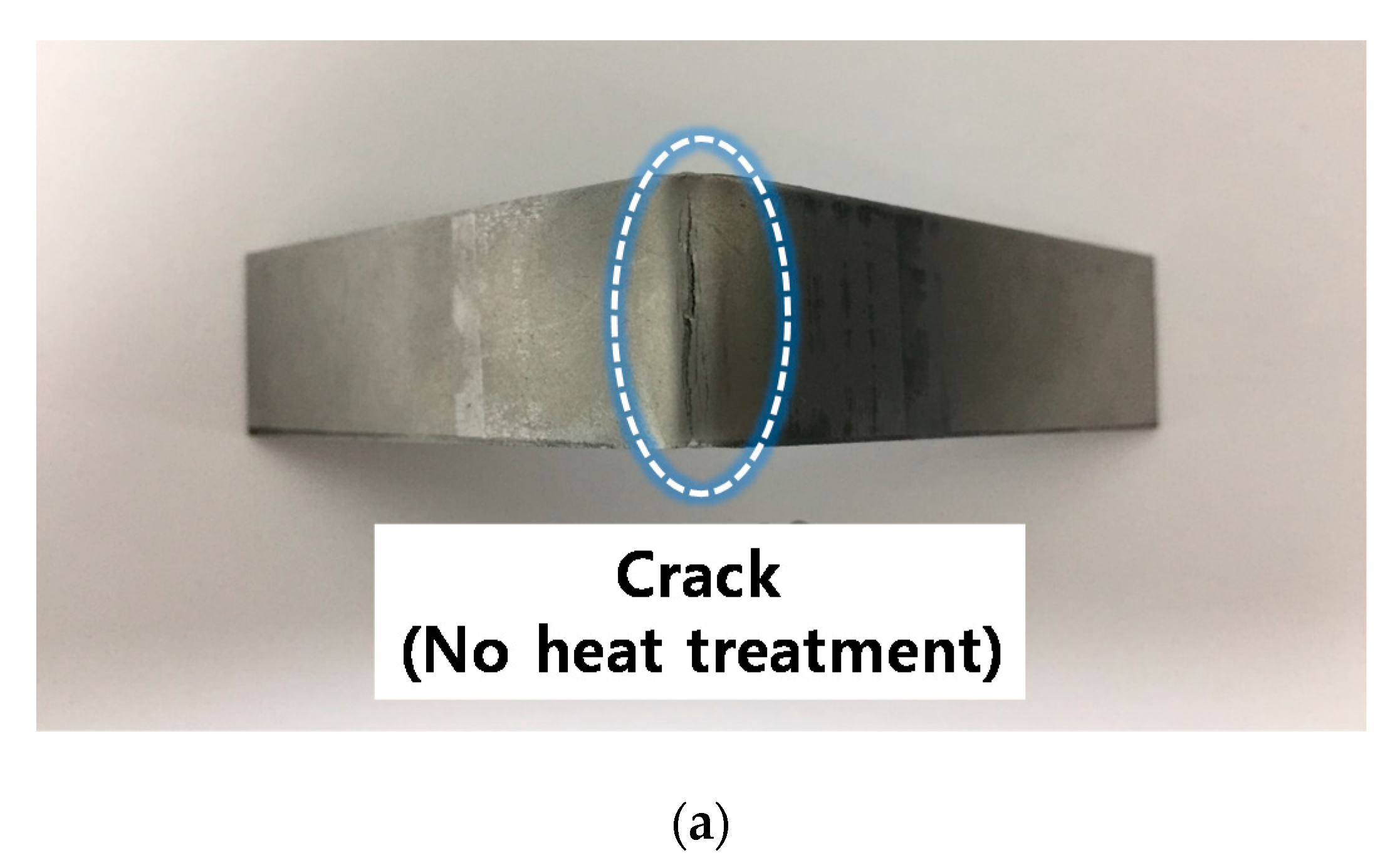
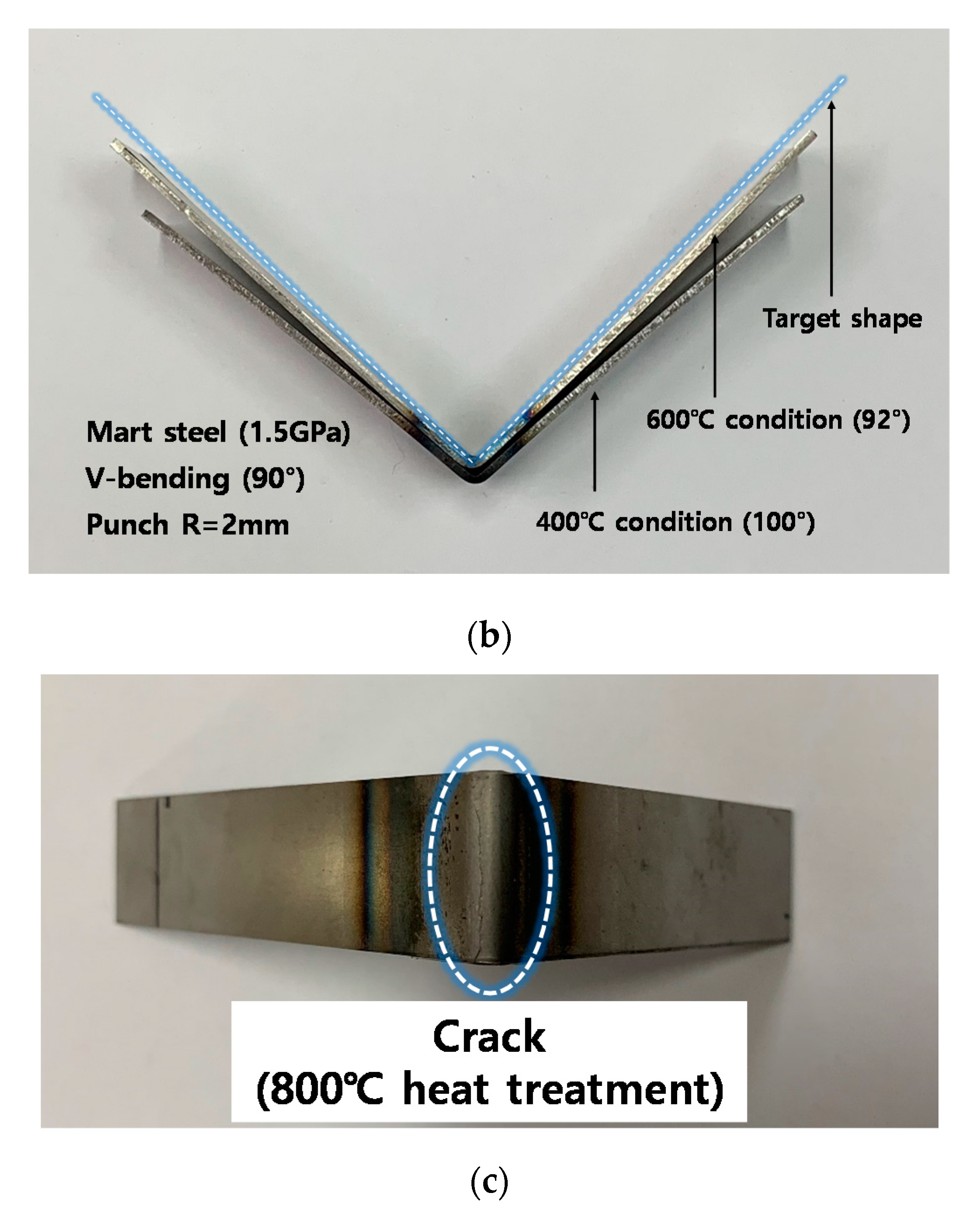
The V-bending test with heat treatment showed that the heat-assisted cold forming can improve the formability and springback problems. The 600 °C heat treatment can avoid cracks and reduce springback, while the 800 °C condition leads to the crack problem again. The tensile test showed that the 600 °C heat treatment can reduce the yield stress, while the 800 °C condition leads to similar results to the as-received material.
(3)
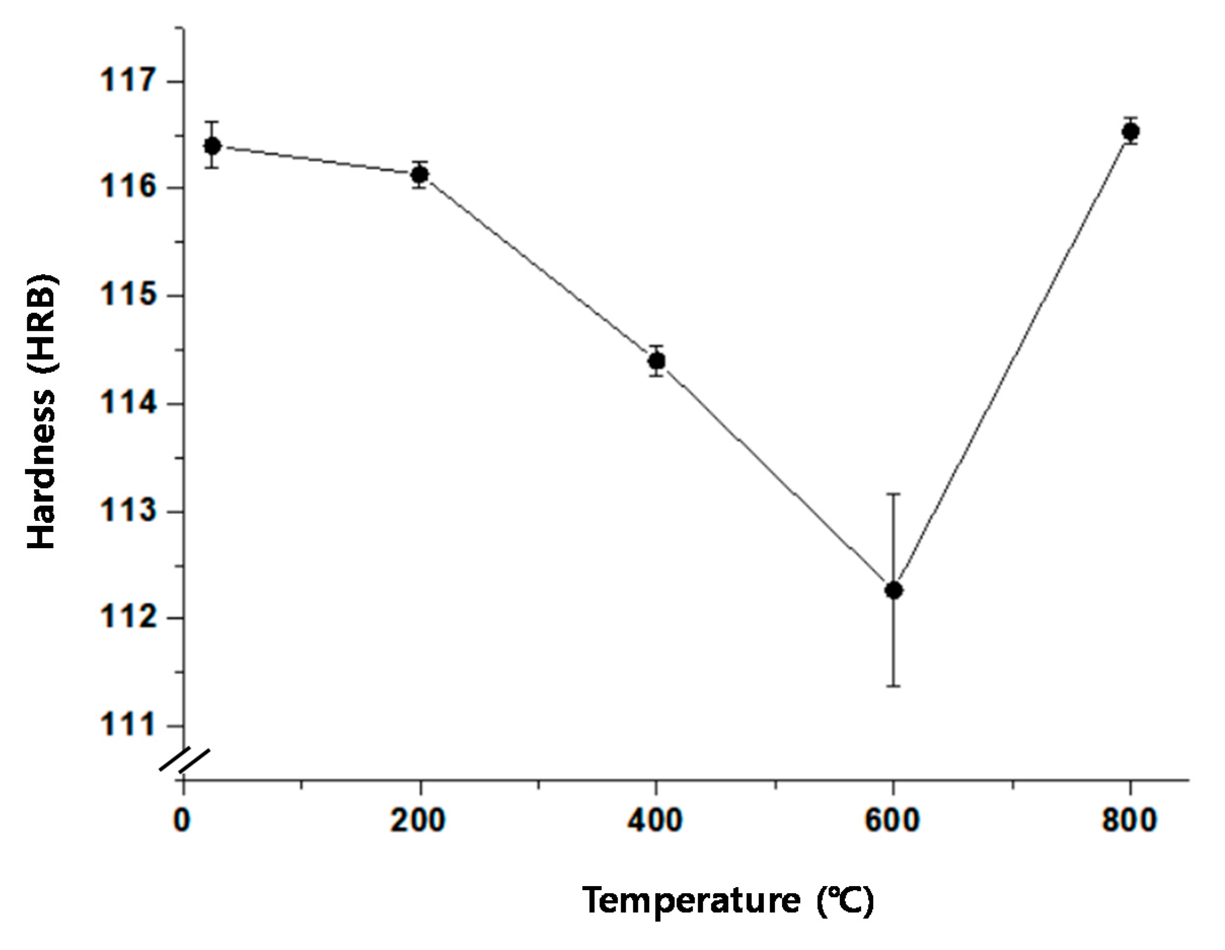
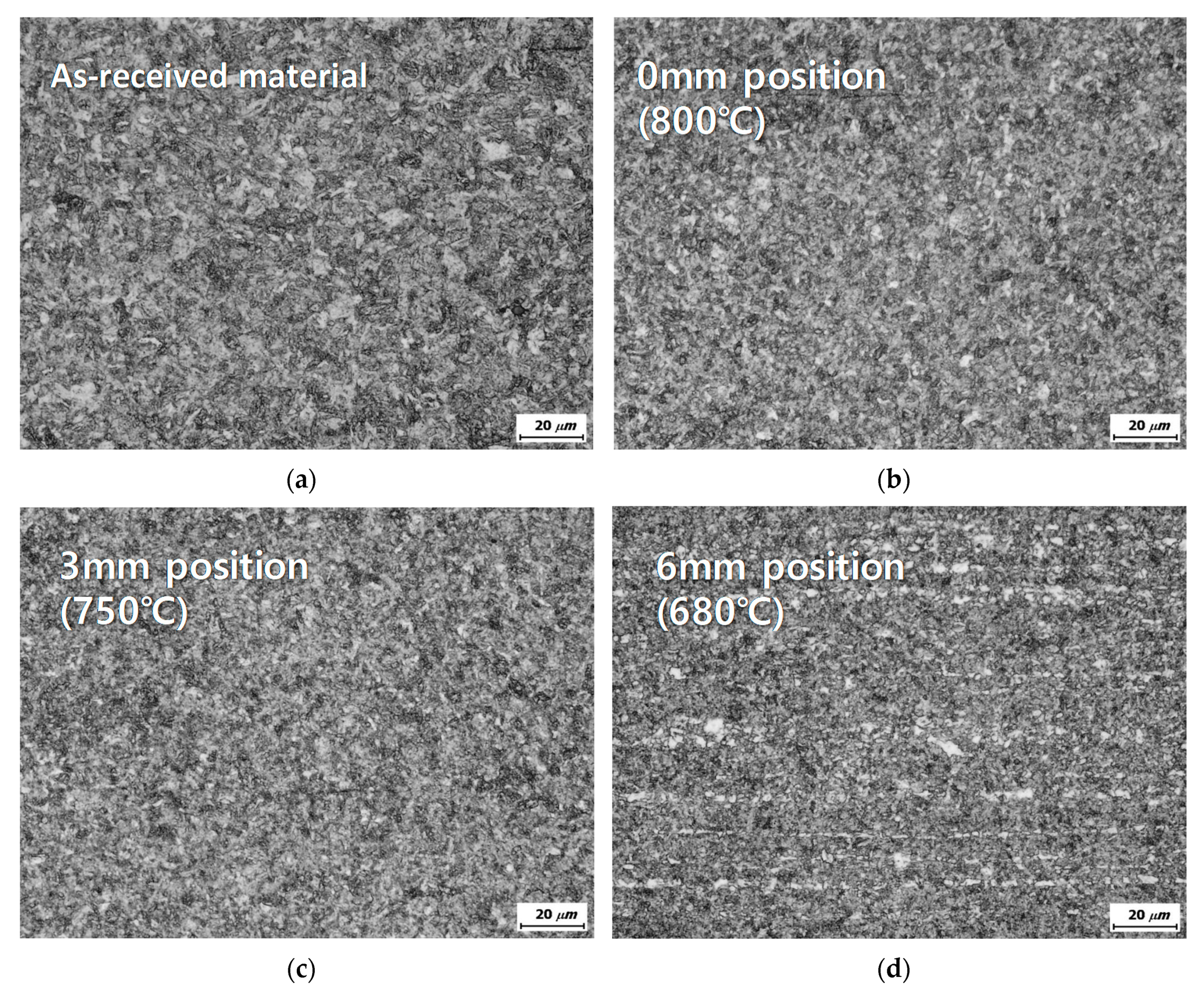
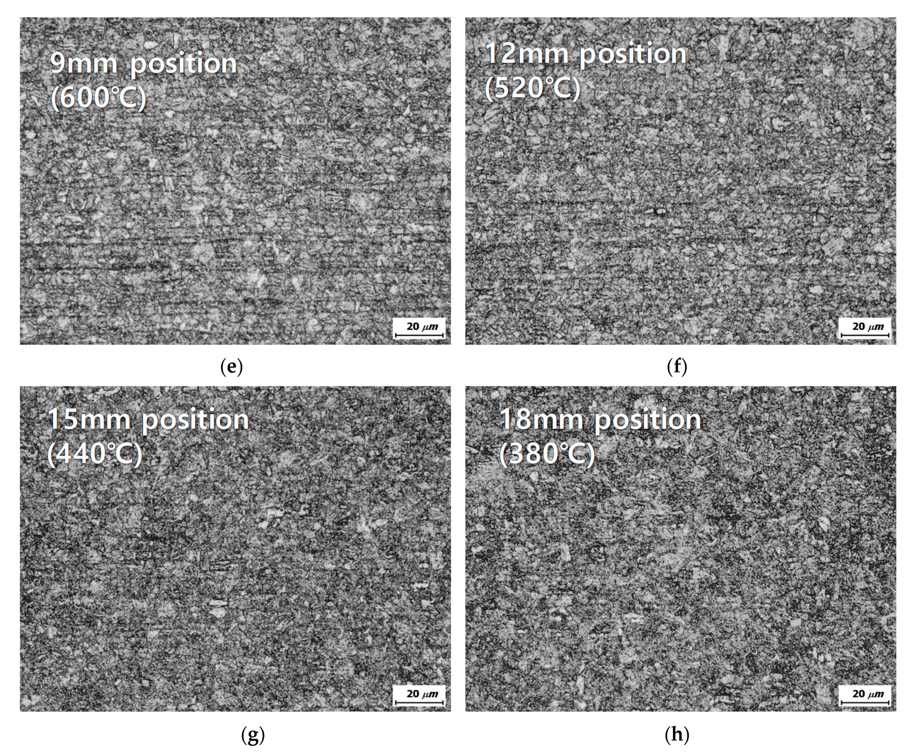
The hardness and microstructure observation showed that 400–600 °C heat-treatment conditions lead to the decomposition of martensite, while ab 800 °C-heat-treatment condition results in a microstructure similar to that of the as-received material. This result is supported by an experiment reported in paper [24] showing that controlling the manganese content can lead to a homogeneous martensitic microstructure, even after air cooling from several heat treatments. These affect the results of the tensile test.
(4)
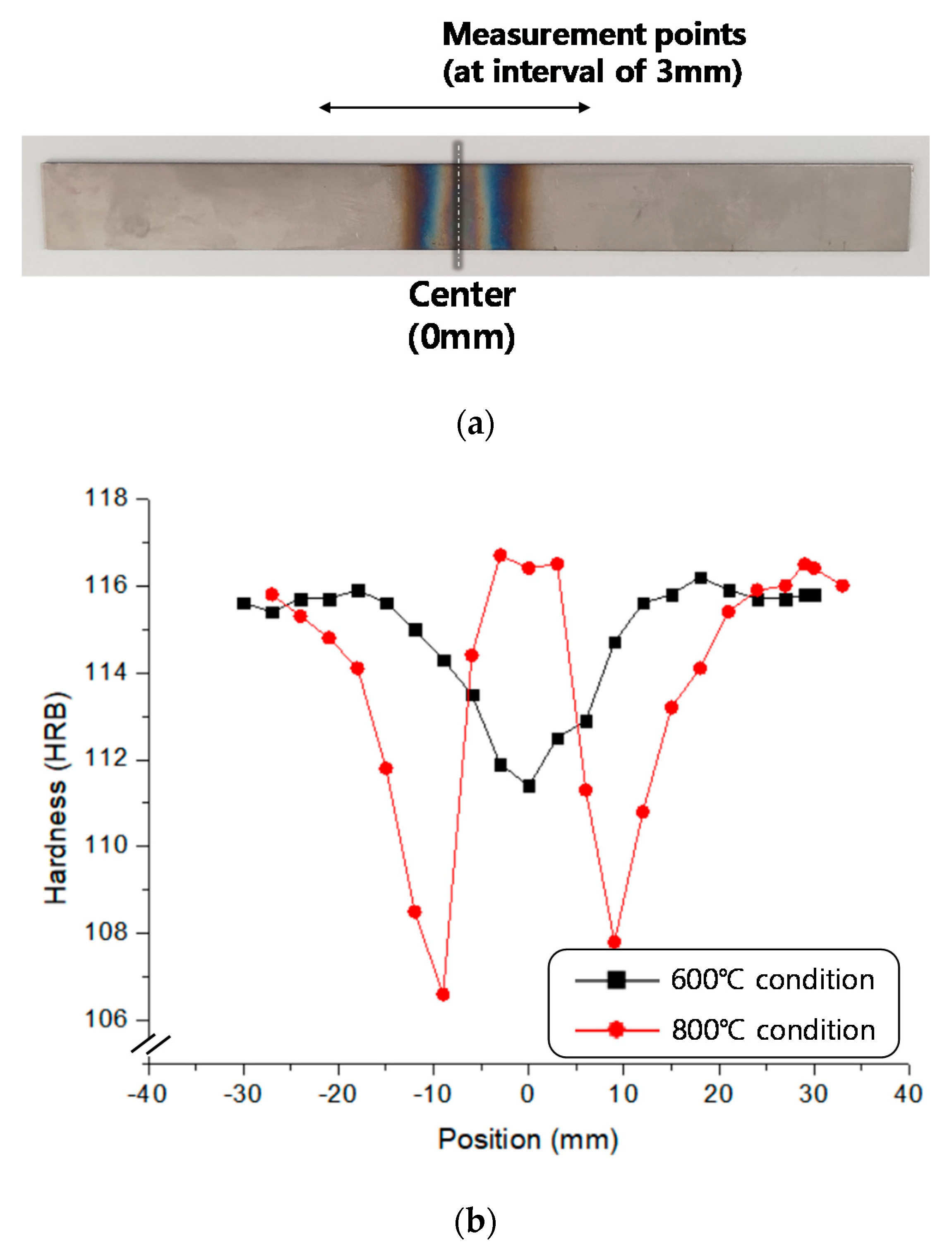
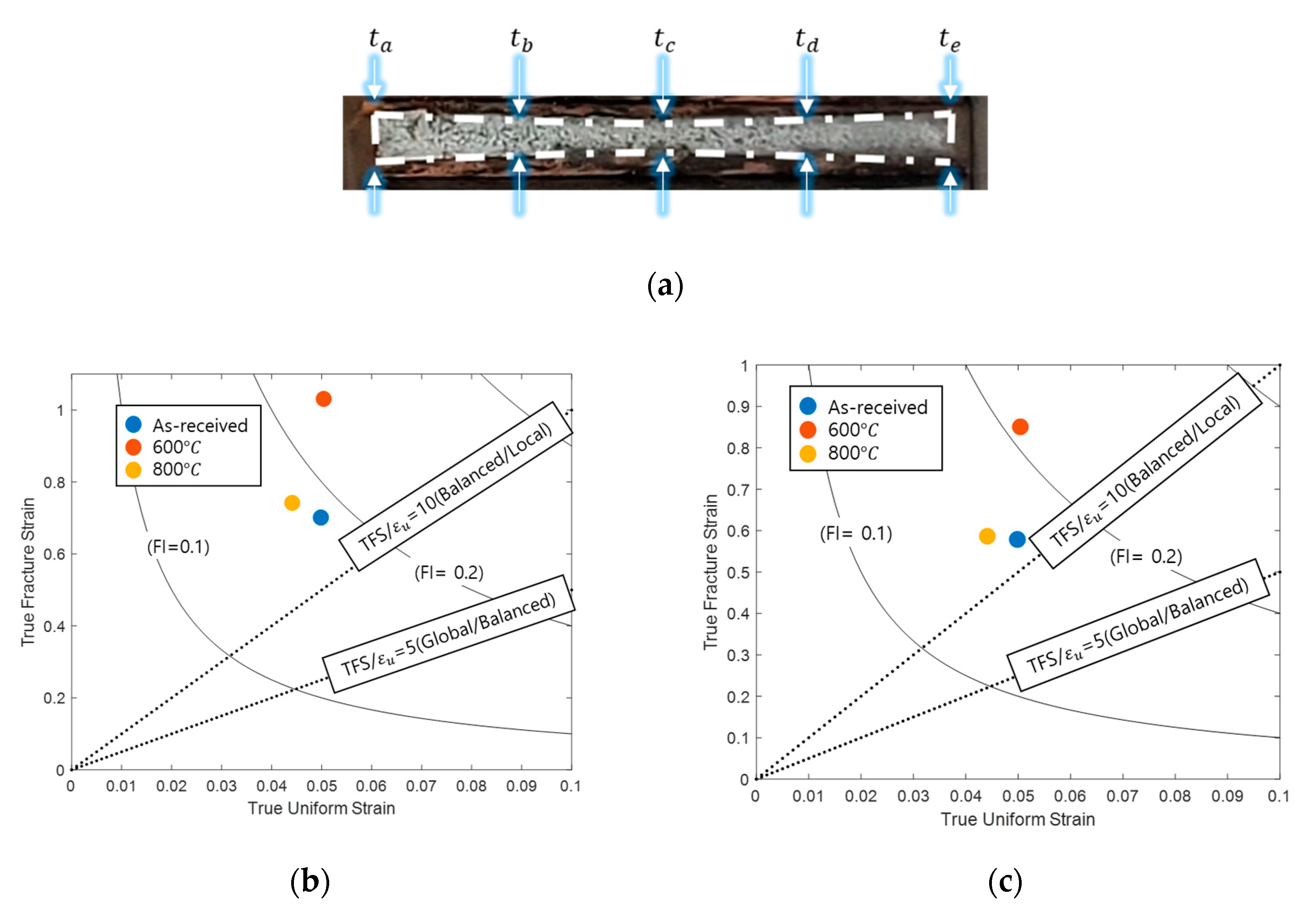
The local formability measurements in this study show that 800 °C IR heat treatment leads to a formability result close to that of the as-received material, while 600 °C IR heat treatment results in clearly improved local formability results. A study [25] showed that a short-time tempering above 600 °C can make the manganese directly embattle the martensite grain boundaries. These support the V-bending test results.
(5)
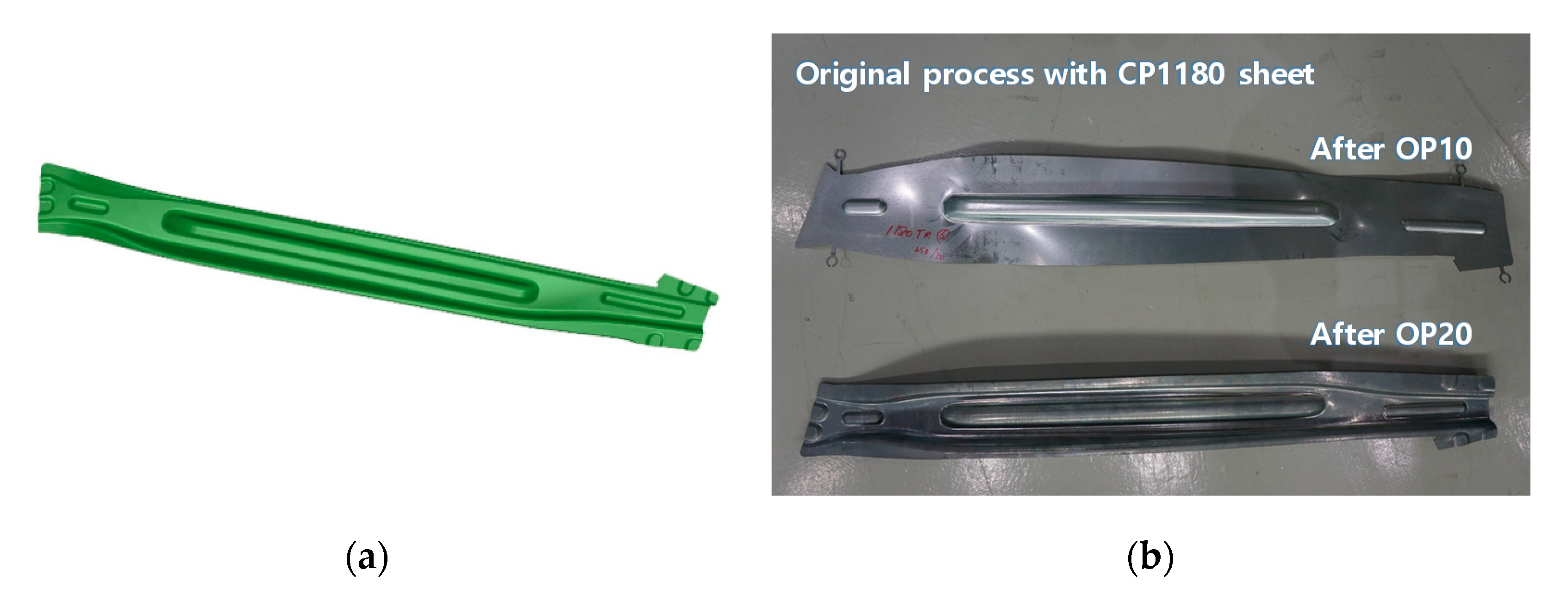
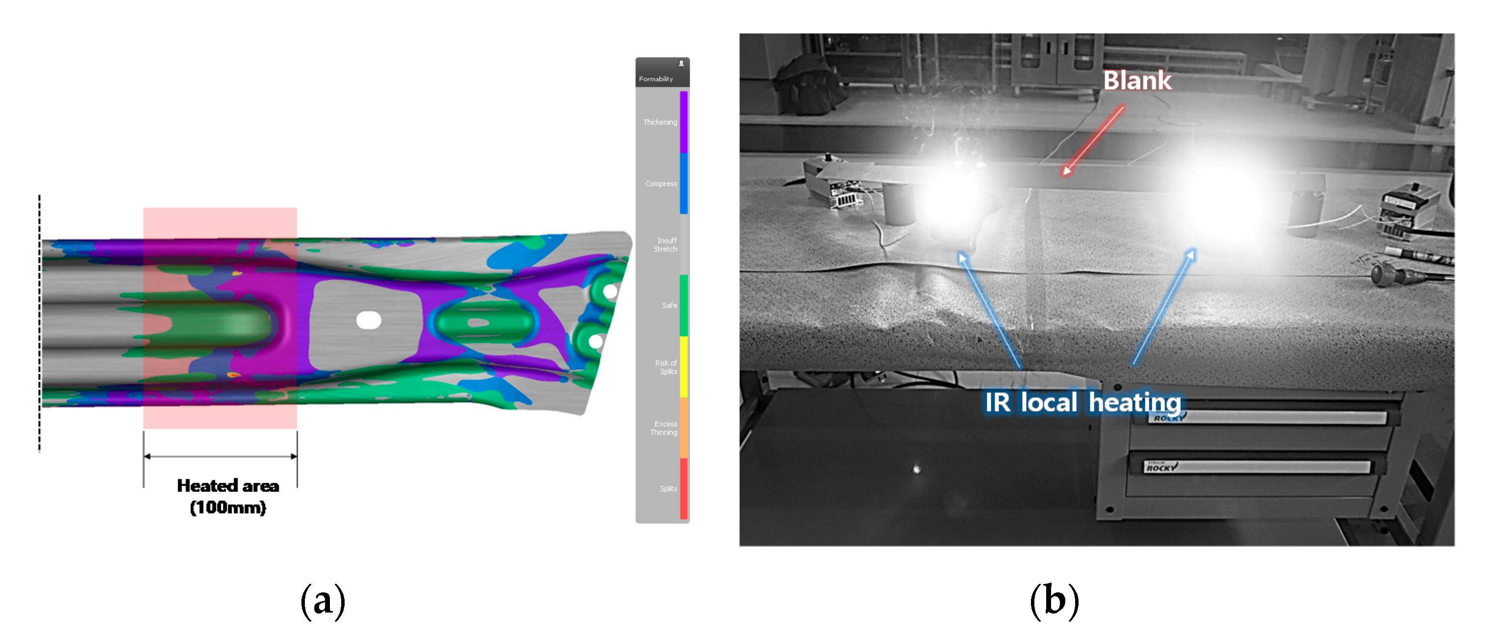
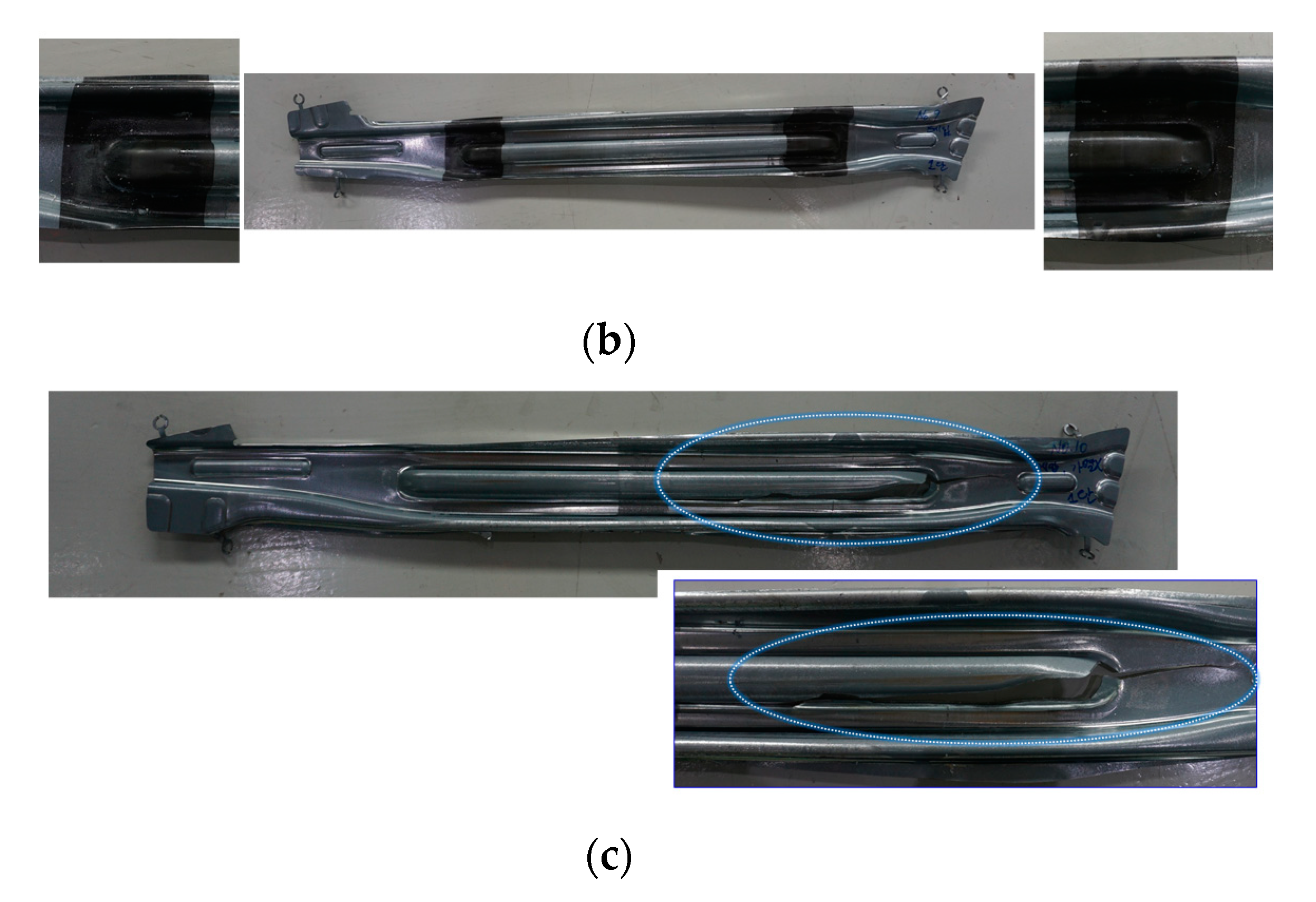
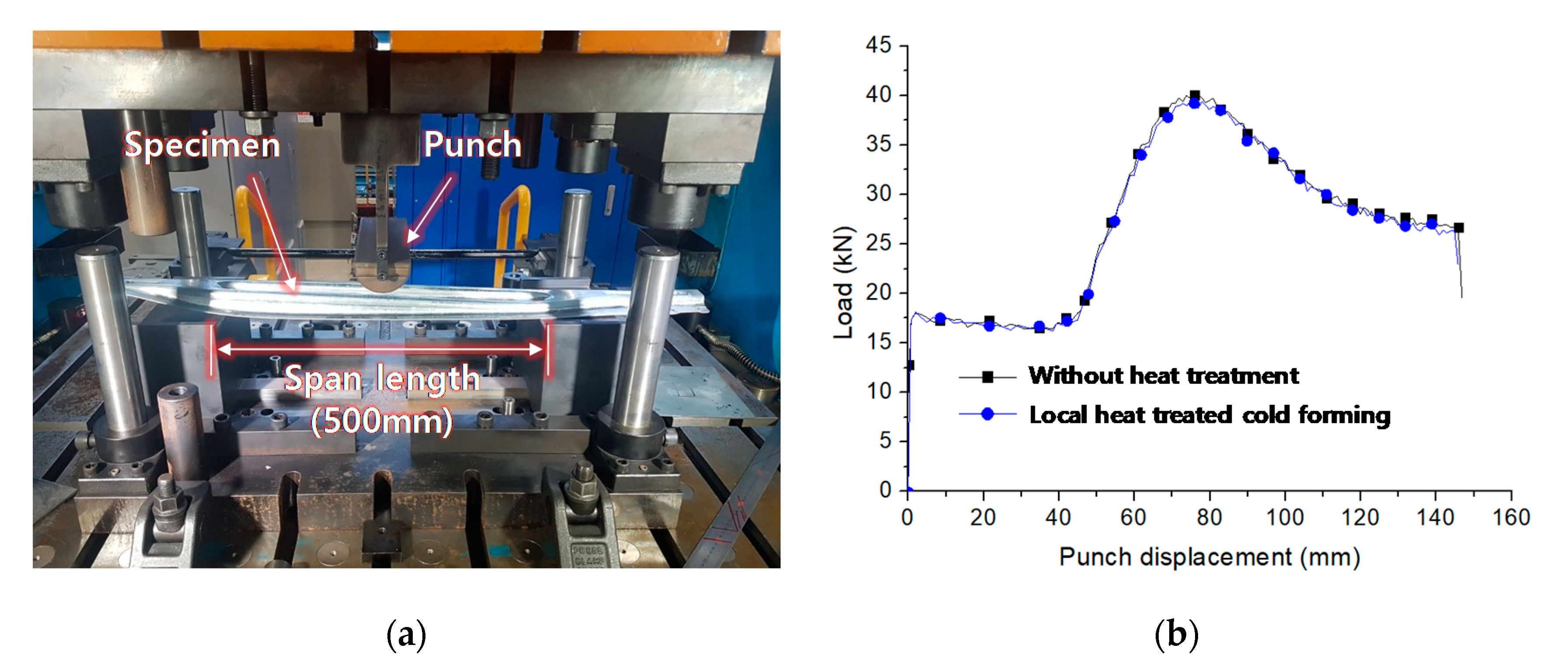
The local-heat-assisted cold stamping successfully manufactured a door impact beam with the MS steel, while cold forming resulted in a large fracture. In addition, the heat-treated door impact beam presented a mechanical strength close to that of the other part manufactured without the heat treatment in the three-point bending test. The results of this work show that heat-assisted cold stamping can be applied to commercial products.

Author Contributions

Conceptualization, E.-H.L., C.H.M., Y.-H.K., and K.K.; methodology, E.-H.L., S.-H.P., and K.-Y.K.; software, J.-Y.P. and H.-Y.L.; validation, E.-H.L., S.-H.P., K.-Y.K., and Y.-H.K.; formal analysis, E.-H.L., C.H.M., Y.-H.K., and K.K.; investigation, C.H.M., Y.-H.K., and K.K.; resources, C.H.M., Y.-H.K., and K.K.; data curation, E.-H.L., S.-H.P., and K.-Y.K.; writing—original draft preparation, E.-H.L. and K.-Y.K.; writing—review and editing, E.-H.L. and K.-Y.K.; visualization, E.-H.L. and K.-Y.K.; supervision, E.-H.L. and K.K.; project administration, E.-H.L. and Y.-H.K.; funding acquisition, C.H.M., Y.-H.K., and K.K. All authors have read and agreed to the published version of the manuscript.

Funding

This research was funded by POSCO.

Conflicts of Interest

The authors declare no conflict of interest.

References

  1. Maeno, T.; Mori, K.I.; Ogihara, T.; Fujita, T. Blanking immediately after heating and ultrasonic cleaning for compact hot-stamping systems using rapid resistance heating. Int. J. Adv. Manuf. Technol. 2018, 97, 3827–3837. [Google Scholar] [CrossRef]
  2. Li, N.; Lin, J.; Balint, D.S.; Dean, T.A. Modelling of austenite formation during heating in boron steel hot stamping processes. J. Mater. Process. Technol. 2016, 237, 394–401. [Google Scholar] [CrossRef]
  3. Thien, N.T.; Jeong, Y.H.; Hong, S.T.; Kim, M.J.; Han, H.N.; Lee, M.G. Electrically assisted tensile behavior of complex phase ultra-high strength steel. Int. J. Precis. Eng. Manuf. Green Technol. 2016, 3, 325–333. [Google Scholar] [CrossRef]
  4. Zhang, P.; Zhu, L.; Luo, S.; Luo, J. Hot stamping forming and finite element simulation of USIBOR1500 high-strength steel. Int. J. Adv. Manuf. Technol. 2019, 103, 3187–3197. [Google Scholar] [CrossRef]
  5. Ganapathy, M.; Li, N.; Lin, J.; Abspoel, M.; Bhattacharjee, D. Experimental investigation of a new low-temperature hot stamping process for boron steels. Int. J. Adv. Manuf. Technol. 2019, 105, 669–682. [Google Scholar] [CrossRef] [Green Version]
  6. Liu, S.; Long, M.; Ai, S.; Zhao, Y.; Chen, D.; Feng, Y.; Duan, H.; Ma, M. Evolution of phase transition and mechanical properties of ultra-high strength hot-stamped steel during quenching process. Metals 2020, 10, 138. [Google Scholar] [CrossRef] [Green Version]
  7. Kong, L.; Peng, Y.; Liu, C. Research on the re-deformation characteristics of hot stamping of boron steel parts with tailored properties. Metals 2020, 10, 1136. [Google Scholar] [CrossRef]
  8. Cui, M.; Wang, Z.; Wang, L.; Huang, Y. Numerical Simulation and Multi-Objective Optimization of Partition Cooling in Hot Stamping of the Automotive B-Pillar Based on RSM and NSGA-II. Metals 2020, 10, 1264. [Google Scholar] [CrossRef]
  9. Karbasian, H.; Tekkaya, A.E. A review on hot stamping. J. Mater. Process. Technol. 2010, 210, 2103–2118. [Google Scholar] [CrossRef]
  10. Mohammad, R.B.; Mahdi, M. Springback investigation at warm V-bending conditions by numerical and experimental methods. In Proceedings of the International Conference on Trends in Mechanical and Industrial Engineering, Bangkok, Thailand, 23–24 December 2011; pp. 185–190. [Google Scholar]
  11. Yang, D.-Y.; Park, J.C.; Seong, D.Y. Development of an Innovative Bending Process Employing Synchronous Incremental Heating and Incremental forming. In Proceedings of the International Conference of Technology of Plasticity (ICTP) 2011, Aachen, Germany, 25–30 September 2011; Verlag Stahleisen GmbH: Dsseldorf, Germany, 2011. [Google Scholar]
  12. Zheng, K.; Lee, J.; Lin, J.; Dean, T.A. A buckling model for flange wrinkling in hot deep drawing aluminium alloys with macro-textured tool surfaces. Int. J. Mach. Tools Manuf. 2017, 114, 21–34. [Google Scholar] [CrossRef]
  13. Shao, Z.; Jiang, J.; Lin, J. Feasibility study on direct flame impingement heating applied for the solution heat treatment, forming and cold die quenching technique. J. Manuf. Process. 2018, 36, 398–404. [Google Scholar] [CrossRef]
  14. Bosetti, P.; Bruschi, S.; Stoehr, T.; Lechler, J.; Merklein, M. Interlaboratory comparison for heat transfer coefficient identification in hot stamping of high strength steels. Int. J. Mater. Form. 2010, 3, 817–820. [Google Scholar] [CrossRef]
  15. Lee, E.H.; Yoon, J.W.; Yang, D.Y. Study on springback from thermal-mechanical boundary condition imposed to V-bending and L-bending processes coupled with infrared rays local heating. Int. J. Mater. Form. 2018, 11, 417–433. [Google Scholar] [CrossRef]
  16. Chen, L.W.; Cai, M.J. Development of a hot stamping clinching tool. J. Manuf. Process. 2018, 34, 650–658. [Google Scholar] [CrossRef]
  17. Quan, G.Z.; An, C.; Qiu, H.M.; Zhang, L.; Wang, X. Influence Factors of Non-uniform Phase Transformation in Hot Stamping Process of Ultra-High-Strength Steel Sheet. Int. J. Precis. Eng. Manuf. 2019, 20, 1169–1183. [Google Scholar] [CrossRef]
  18. Casellas, D.; Lara, A.; Frómeta, D.; Gutiérrez, D.; Molas, S.; Pérez, L.; Rehrl, J.; Suppan, C. Fracture Toughness to Understand Stretch-Flangeability and Edge Cracking Resistance in AHSS. Metall. Mater. Trans. A Phys. Metall. Mater. Sci. 2017, 48, 86–94. [Google Scholar] [CrossRef]
  19. Lee, E.H.; Yang, D.Y.; Yoon, J.W.; Yang, W.H. A manufacturing process using the infrared ray local heating method for seat cross members. Int. J. Adv. Manuf. Technol. 2017, 89, 3299–3305. [Google Scholar] [CrossRef]
  20. Lee, E.H.; Yang, D.Y.; Yoon, J.W.; Yang, W.H. Numerical modeling and analysis for forming process of dual-phase 980 steel exposed to infrared local heating. Int. J. Solids Struct. 2015, 75–76, 211–224. [Google Scholar] [CrossRef]
  21. Neugebauer, R.; Scheffler, S.; Poprawe, R.; Weisheit, A. Local laser heat treatment of ultra high strength steels to improve formability. Prod. Eng. 2009, 3, 347–351. [Google Scholar] [CrossRef]
  22. Lee, E.H.; Kim, W. sung Electrical–Thermal–Mechanical Analysis of Focused Infrared Heating Process. Int. J. Precis. Eng. Manuf. Green Technol. 2020, 7, 885–903. [Google Scholar] [CrossRef]
  23. Lee, E.H.; Yang, D.Y. Experimental and numerical analysis of a parabolic reflector with a radiant heat source. Int. J. Heat Mass Transf. 2015, 85, 860–864. [Google Scholar] [CrossRef]
  24. Gramlich, A.; Schmiedl, T.; Schönborn, S.; Melz, T.; Bleck, W. Development of air-hardening martensitic forging steels. Mater. Sci. Eng. A 2020, 784, 139321. [Google Scholar] [CrossRef]
  25. Kuzmina, M.; Ponge, D.; Raabe, D. Grain boundary segregation engineering and austenite reversion turn embrittlement into toughness: Example of a 9 wt.% medium Mn steel. Acta Mater. 2015, 86, 182–192. [Google Scholar] [CrossRef]
  26. Shi, J.; Hu, J.; Wang, C.; Wang, C.Y.; Dong, H.; Cao, W.Q. Ultrafine grained duplex structure developed by ART-annealing in cold rolled medium-mn steels. J. Iron Steel Res. Int. 2014, 21, 208–214. [Google Scholar] [CrossRef]
  27. Grajcar, A.; Kuziak, R.; Zalecki, W. Third generation of AHSS with increased fraction of retained austenite for the automotive industry. Arch. Civ. Mech. Eng. 2012, 12, 334–341. [Google Scholar] [CrossRef]
  28. Aydin, H.; Essadiqi, E.; Jung, I.H.; Yue, S. Development of 3rd generation AHSS with medium Mn content alloying compositions. Mater. Sci. Eng. A 2013, 564, 501–508. [Google Scholar] [CrossRef]
  29. Heo, N.H.; Nam, J.W.; Heo, Y.U.; Kim, S.J. Grain boundary embrittlement by Mn and eutectoid reaction in binary Fe-12Mn steel. Acta Mater. 2013, 61, 4022–4034. [Google Scholar] [CrossRef]
  30. Nasim, M.; Edwards, B.C.; Wilson, E.A. A study of grain boundary embrittlement in an Fe–8%Mn alloy. Mater. Sci. Eng. A 2000, 281, 56–67. [Google Scholar] [CrossRef]
  31. Golling, S.; Frómeta, D.; Casellas, D.; Jonsén, P. Influence of microstructure on the fracture toughness of hot stamped boron steel. Mater. Sci. Eng. A 2019, 743, 529–539. [Google Scholar] [CrossRef]
  32. Hance, B. Advanced High-Strength Steel (AHSS) Performance Level Definitions and Targets. SAE Int. J. Mater. Manuf. 2018, 11, 505–516. [Google Scholar] [CrossRef]
  33. Denks, I.A.; Schneider, M.; Westhäuser, S.; Lesch, C. On the Correlation between Suitable Material Parameters for the Prediction of Local Formability of Advanced High Strength Steels. Steel Res. Int. 2019, 90, 1–16. [Google Scholar] [CrossRef]
  34. Kim, K.; Song, Y.; Yang, W.; Choi, H.; Park, S.H.; Yoon, J. Partial strengthening method for cold stamped B-pillar with minimal shape change. Int. J. Adv. Manuf. Technol. 2019, 102, 4241–4255. [Google Scholar] [CrossRef]
Figure 1. Concept of local heat-assistant cold forming.
Metals 10 01543 g001
Figure 2. Local heating test.
Metals 10 01543 g002
Figure 3. Results of the local heating test; (a) Heating and cooling rate at each measurement position; (b) Temperature distributions.
Metals 10 01543 g003
Figure 4. Experimental setting of the V-bending.
Metals 10 01543 g004
Figure 5. V-bending results: (a) Crack on the non-heat-treated specimen; (b) Bent angle; (c) Crack on the 800 °C-treated specimen.
Metals 10 01543 g005aMetals 10 01543 g005b
Figure 6. Hardness measurement with respect to the heat-treatment temperature.
Metals 10 01543 g006
Figure 7. Tensile test after the IR heat treatment.
Metals 10 01543 g007
Figure 8. Hardness distribution of the 600 and 800 °C-heat-treated specimens: (a) Hardness measurement setting; (b) Hardness distribution.
Metals 10 01543 g008
Figure 9. Microstructure observation with respect to heated position: (a) As-received material; (b) 0 mm position; (c) 3 mm position; (d) 6 mm position; (e) 9 mm position; (f) 12 mm position; (g) 15 mm position; (h) 18 mm position.
Metals 10 01543 g009aMetals 10 01543 g009b
Figure 10. Local formability: (a) Cross section of a fracture specimen after the tensile test; (b) T F S a r e a ; (c) T F S t h i c k n e s s .
Metals 10 01543 g010
Figure 11. Target door impact beam: (a) Modeling of the target door impact beam; (b) Original process (OP10 and OP20) with CP1180 sheet.
Metals 10 01543 g011
Figure 12. Heat treatment for the door impact beam application: (a) Heat treatment area on the left side of the door impact beam; (b) Heat treatment process.
Metals 10 01543 g012
Figure 13. Door impact beam application: (a) Press setting; (b) Manufactured door impact beam with local-heat-treatment cold forming; (c) Without heat treatment.
Metals 10 01543 g013aMetals 10 01543 g013b
Figure 14. Three-point bending test for the door impact beam: (a) Experimental setting; (b) Load–displacement curves.
Metals 10 01543 g014
Table 1. Material properties of the CR1470M steel (rolling direction).
CR1470M
(Mart 1.5 GPa)
0.2% Yield Stress (MPa)Tensile Strength (MPa)Uniform Elongation
(%)
Total Elongation
(%)
Normal R-Value
1224.815475.17.61.466
Table 2. Results of the V-bending.
CR1470M
(Mart 1.5 GPa)
No Heat Treatment200 °C
Condition
400 °C
Condition
600 °C
Condition
800 °C
Condition
CrackCrack100°
bend angle
92°
bend angle
Crack
Publisher’s Note: MDPI stays neutral with regard to jurisdictional claims in published maps and institutional affiliations.

