1. Introduction
Sintered steel parts are well-known for the economic manufacturing of complex shapes, and are widely used in transmission systems. Within the manufacturing process of conventional powder metallurgy (PM), material porosity is adjusted by varying the density of the sintered steel, which influences the mechanical properties significantly. A density between 7.1 and 7.2 g/cm³ is assumed as the transition area from an open to closed porosity (Dizdar [
1], Lipp [
2]). The term open porosity refers to the pores on the surface directly connected to the porous bulk material, so that the open pores can be used as transport channels (Dlapka et al. [
3]). Sintered material with an open porosity can be impregnated with lubricant in order to provide intrinsic self-lubrication.
In lightly-loaded sintered journal bearings, the porosity of the sintered material has been already exploited for self-lubrication for many years. Kaneko and Obara [
4] experimentally investigated the lubrication mechanism of porous journal bearings with a simplified test bearing. Using a dye-injection method, they observed that in a hydrodynamic lubrication regime, the oil in the porous matrix flows away from the loaded towards the unloaded zone. Pahl and Goller [
5], and Bartz and Rübenbach [
6] give an overview of the friction behavior, common materials, and lubricants for sintered journal bearings. Matzner et al. [
7] analyzed the influence of various parameters, including the permeability on the load-carrying capacity of the sintered journal bearings. They found that because of a lack of knowledge about the relationship between the manufacturing parameters and material permeability, the significant influence of the lubricant transport to the loaded contact zone on the operating behavior can be roughly approximated. Morgan and Cameron [
8] were one of the first to calculate the lubricant circulation from the loaded to the unloaded zone in the porous journal bearings. Balasoiu et al. [
9] calculated the oil flow in the porous journal bearings in detail. They confirmed the presence of lubricant-circulation, and found a decreasing load-carrying capacity with an increasing permeability. Also, Scheichl et al. [
10] conducted simulations on the oil flow in sintered journal bearings, and showed that oil bleeds primarily in unloaded zones next to the loaded contact zone. Zhang et al. [
11] investigated the effect of the porous surfaces of multilayer journal bearings on the lubrication, and recommend a low permeable surface.
Further studies on oil-impregnated sintered materials not related to journal bearings have been performed. Fote et al. [
12] and Marchetti et al. [
13,
14] studied self-lubricating sintered materials for space applications. They found that the bleeding of the lubricant is mainly caused by capillary effects due to the surface roughness, different thermal expansion of porous material, and lubricant, as well as to centrifugal forces. Li, Sosa, and Oloffson [
15] compared the tribological behavior of wrought and sintered steels by using a pin-on-disk test rig. They described an improved wear resistance of sinterd parts with an open porosity because of an improved lubrication. In a more recent study, Li and Oloffson [
16] found a correlation between the pore size, friction coefficient, and wear coefficient, and described peeling as one of the main failure modes.
The surface pores of oil-impregnated sintered materials led to the local phenomena in the tribological contacts. For elastohydrodynamically-lubricated (EHL) contacts, the effect of pores on the surface, which are not connected to the pore network in the sintered material (i.e., “closed” pores), may be compared to the effect of surface indentation. Its local effect on the lubricant film thickness in rolling–sliding point contacts was studied in detail by several researchers. Wedeven and Cusano [
17,
18] provided the first experimental evidence of film thickness variations around the indentation and implication to pressure distribution. Kaneta et al. [
19,
20] described a film thickness reduction in the vicinity of an indentation when it enters the edge of the central contact zone. Mourier et al. [
21,
22] showed, with numerical simulation and experiments, that the deep dents lead to a film reduction and breakdown, while the shallow dents increase the lubricant film thickness. Krupka et al. [
23] further described the effect of the shallow dent geometry and conditions. Furthermore, they focused on the mixed lubrication regime [
24] and start–stop and reversal motion [
25].
Research on sintered gears has mainly been aimed at improving the mechanical properties and load-carrying capacity by densification of the tribologically stressed flank surfaces. The corresponding studies are based on conventional dip- or injection-lubrication. Frech et al. [
26] investigated the cold rolling process for surface densification. They evaluated the influence of the process parameters on the density depth profile of sintered gears. Dizdar [
1] reviewed various investigations on the pitting resistance of sintered small-module gears, and showed that the highest pitting resistance was for the manufacturing steps pressing, sintering, surface densification, and case-carburizing. Sandner et al. [
27] performed experiments at a three-shaft gear test rig. They showed that sintered gears with a subsequent surface densification process can bear loads in the order of magnitude of wrought steel gears. Yoshida et al. [
28] compared the surface durability of induction-hardened sintered gears with induction-hardened melted steel gears at a power circulating gear test rig. The surface durability was shown to be lower for the sintered gears. Pitting and spalling were observed as the main failure modes.
Ebner et al. [
29] were the first to study the self-lubrication of oil-impregnated sintered materials in highly-loaded contacts. They confirmed its general functionality using experimental investigations at a twin-disk test rig and an efficiency gear test rig [
30]. Different operating behaviors were correlated to the surface porosity of the test specimens at the end of the experiments. In Omasta et al. [
31], the authors confirmed lubricant film formation in EHL contacts with oil-impregnated sintered materials by observing the film thickness using optical interferometry. The findings show that starvation is likely to occur, the lubricant film thickness is mainly governed by the oil bleeding capacity, and the oil starvation parameters correlate well with the classic starved EHL theory.
The literature review shows that a lot of research has been performed on the self-lubricating mechanism of oil-impregnated sintered journal bearings. Experimental investigations on sintered gears have been focused on the densification of the flank surface and external lubrication. However, no systematic investigations on the self-lubrication of oil-impregnated sintered materials in highly-loaded contacts (e.g., gears) have been conducted. The first investigations of the authors [
29] show that detailed analyses on the local effects of surface porosity in tribological contacts are necessary in order to understand and improve the operating behavior of self-lubricating sintered materials for highly-loaded applications. This has been addressed in this study by considering the various surface finishes with different surface porosities. Their operating behaviors are investigated by endurance measurements using a twin-disk test rig. The local effects of the surface pores in the highly-loaded EHL contacts are investigated using the optical film thickness measurements by means of thin film colorimetric interferometry.
2. Experimental Setups
The experimental setups of the twin-disk test rig and optical tribometer, as well as the considered materials, operating condition, and lubrication, are presented in the following sections.
2.1. Twin-Disk Test Rig
A FZG twin-disk test rig was used to investigate the influence of various surface finishes on the operating behavior of highly-loaded contacts with oil-impregnated sintered material.
2.1.1. Mechanical Setup
Figure 1 shows the mechanical layout of the FZG twin-disk test rig according to Michaelis [
32]. The following description of the test rig is based on the work and formulations of Lohner et al. [
33] and Ebner et al. [
29,
34].
The upper and lower disk were press-fitted onto shafts, which were individually rotated by two speed-controlled electric motors. This allowed for the continuous variation of the surface velocities, and , of the disks. The normal force, , in the contact was continuously applied by a pneumatic cylinder via a pivot arm, where the upper disk was mounted. The lower disk was mounted in a skid, which was attached to the frame by thin steel sheets. The skid was supported laterally by a load cell, so that the friction force, , in the disk contact for sliding velocities, ≠ 0 m/s, could be measured as a reaction force, with hardly any skid displacement. The normal force, , friction force, , and surface velocities, and , were measured. Additionally, the bulk temperature of the upper disk, , was measured 5 mm below the disk surface using a Pt100 resistance temperature sensor.
The sum velocity,
, and sliding velocity,
, are defined as follows:
The coefficient of friction,
, is obtained by the following:
All of the experiments at the FZG twin-disk test rig were conducted using cylindrical disks with a diameter of
= 80 mm and a width of
= 5 mm (
Figure 1, right). Hence, a line contact was formed. To ensure an evenly distributed load over the disk width of 5 mm, a contact print on aluminum foil was evaluated before each test, and any misalignment was carefully corrected mechanically.
2.1.2. Test Disks
In accordance with the configuration in
Figure 1, the upper disk was made of the sintered steel Sint-D31 (Miba [
36], DIN30910-4 [
37]) with a volume-based porosity of about
= 10%, whereas the lower disk was made of solid steel 16MnCr5 (Deutsche Edelstahlwerke [
38]).
Table 1 summarizes the corresponding material properties and shows the much smaller Young’s modulus of Sint-D31 compared to solid steel. Both of the disks were case-hardened, with a target case-hardening depth of CHD
550HV1 = 0.8 + 0.2 mm and a target surface hardness of 690–740 HV1. Note that the case hardening depth of the sintered disk was CHD
550HV1 > 1.0 mm, because of the open porosity.
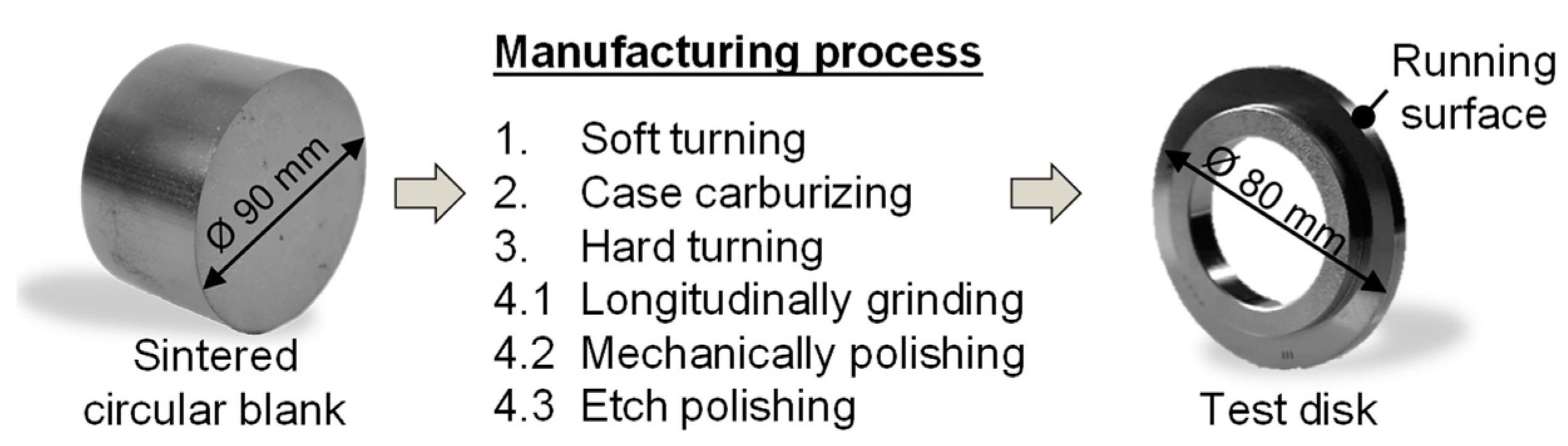
Figure 2 illustrates the manufacturing process of a test disk made from sintered steel. Circular blanks were conventionally sintered to a near-net-shape and were post-processed. After the soft turning and case carburizing, the test disks were hard turned and ground to the geometry in
Figure 1 (right). Three surface finishes, including longitudinally-ground with
~ 0.15 μm, mechanically-polished with
~ 0.01 μm, and etch–polished, were considered. The surface conditions of the sintered disks are documented in detail in
Section 3.2.
In order to avoid the roughness influences from the solid steel disk as much as possible, it was mechanically polished to an arithmetic mean roughness of < 0.01 μm.
All of the roughness measurements were determined using the profile method with a measurement length of = 4 mm and a cut-off wavelength of = 0.8 mm for the longitudinally ground surfaces, and = 0.08 mm for the polished surfaces. All of the roughness parameters were given as mean values of three measurement points evenly distributed over the circumference. For the etch–polished surface, the roughness measurement was left out, as it was not meaningful because of the high surface porosity and its influence on the measurement.
2.1.3. Operating Condition
The operating condition considered was in accordance with previous investigations [
29,
34], and is summarized in
Table 2. The kinematics corresponded to the lower solid disk faster than the upper sintered disk (
vg > 0 m/s with
v1 >
v2).
The operating condition was kept constant for each surface finish of the sintered disk paired with the polished solid steel disk. The designations for the disk pairings were ground–polished, polished–polished, and etched–polished.
2.2. Optical Tribometer
The local effects of the porosity on the lubricant film thickness in highly-loaded EHL contacts were investigated using an optical tribometer based on thin film colorimetric interferometry.
2.2.1. Mechanical Setup and Measurement Technique
Figure 3 shows the mechanical layout of the optical tribometer according to Omasta et al. [
31]. In the tribometer, a transparent disk made from BK7 glass is loaded using a dead-weight lever mechanism against a cylindrical sintered disk. Both of the disks were separately driven by two speed-controlled electric motors, which allowed continuous variation of the sum and sliding velocity. The definitions of the sum velocity,
, and sliding velocity,
, are in accordance with the twin-disk test rig (Equations (1) and (2)).
The glass disk was equipped with a thin chromium layer on the contact side, with the sintered disk that allowed for an optical interference to occur. The contact was observed through an industrial microscope and was illuminated episodically with a high-intensity xenon continuous lamp. The resulting color interferograms were recorded using a high-speed CMOS camera with a frame rate of 8000 fps. The lubricant film thickness was evaluated using the thin film colorimetric interferometry technique [
39]. An optical interference is a physical effect that occurs when two light beams reflected from nearby interfaces are composed together. In the case of the disk-on-disk optical tribometer, the first interface was between the thin chromium layer deposited on the glass disk and the oil film, and the second interface was between the disk and the oil film. As a result, color interferograms occurred, where each color corresponds to a specific film thickness. The conversion to the lubricant film thickness was made using a color-matching algorithm and CIELAB color-film thickness calibration integrated in the AChILES software.
2.2.2. Test Disks
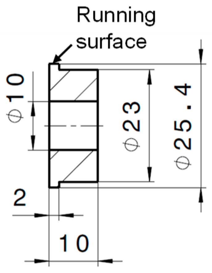
The sintered disk for the optical tribometer was cylindrical, with a diameter of 25.4 mm and a running surface with a width of 2 mm (see
Figure 4). The sintered disk was made from the sintered steel Sint-D31, with the same procedure as described in
Section 2.1.2. To investigate the local influence of pores in EHL contacts in detail, the running surface was mechanically polished to an arithmetic mean roughness of
< 0.01 μm.
2.2.3. Operating Condition
The local effects of the sintered material with a porous surface on the lubricant film thickness were evaluated under the operating conditions defined in
Table 3. The maximum Hertzian pressure and sum velocity were lower compared to the FZG twin-disk test rig, with respect to the mechanical limits of the optical tribometer.
2.3. Lubrication
The sintered disks for the twin-disk test rig and optical tribometer were impregnated with oil in order to obtain self-lubrication.
In accordance with previous studies [
29], the oils FVA3 and FVA3+PD were considered for the twin-disk test rig. FVA3 is an ISO VG 100 mineral oil [
40], and FVA3+PD has the same base oil and a plastic deformation (PD) additive incorporated. Further information on FVA3+PD and its tribofilm characteristics can be found in Lohner et al. [
33] and Emrich et al. [
41]. In terms of self-lubrication with oil-impregnated sintered materials, FVA3 provided a reference with a comparably large experimental basis [
29], whereas FVA3+PD showed promising results on the operating behavior with low coefficients of friction [
30].
For the disks for the optical tribometer, a lower viscosity oil FVA2 (ISO VG 32 mineral oil according to [
40]) was used instead of FVA3, as a result of technological issues of the impregnation device.
The oil was impregnated by pressurization from the bore in radial direction, until oil bleeding was detected on the running surface of the disks. For the sintered disk for the twin-disk test rig,
Figure 5 exemplifies that the average weight gain is
~ 2.1 g when impregnating FVA3 or FVA3+PD. This is consistent with the calculated weight gain based on the volume-based porosity of ~10%.
In order to press-fit the sintered disks onto the shaft of the twin-disk test rig, the shaft was cooled down in liquid nitrogen to avoid oil loss due to an increase of the bulk temperature. The test disks for the optical tribometer were mounted with a transition tolerance on the shaft, and were fixed in an axial direction.
For the self-lubrication on the twin-disk test rig, only the oil bleeding from the sintered disk was available for lubrication. In order to avoid dry lubrication during the first load cycles, the running surface of the solid steel disk of the twin-disk test rig was wetted with an initial lubricant volume of 0.02 mL before each test run. The same procedure was used in the tests on the optical tribometer, so as to avoid lubricant starvation.
4. Experimental Results
In this section, the experimental results from the twin-disk test rig on the influence of the different manufacturing steps and surface finishes are shown. This is supplemented by in-depth analyses on the local effects of the surface porosity in highly-loaded EHL contacts.
4.1. Twin-Disk Test Rig
Figure 10 shows the measurement results of the coefficient of friction (top) and related bulk temperature (bottom) for the considered disk pairings at
= 1043 N/mm
2,
= 4.0 m/s and
= 0.4 m/s, in comparison with the lubricants FVA3 (left) and FVA3+PD (right). Information about the preparation of the samples are given in
Section 2.1.2 and
Section 3.2. The results with the surface combination ground–polished are added to the results published previously [
29].
All of the experiments with FVA3 and FVA3+PD showed a clear back coupling between the profile of the bulk temperature and the coefficient of friction. The tests were stopped because of high coefficients of friction (μ > 0.12) or high bulk temperatures ϑM2 > 150 °C. Furthermore, two tests with disk pairing ground–polished were stopped manually at 2.2-M and 0.65-M load cycles, and one test with disk pairing polished–polished was stopped manually after 0.64-M load cycles. The following description is separated into the investigated disk pairings.
With the impregnated oil FVA3, the disk pairing ground–polished shows stable (stationary), metastable (oscillating), and unstable (non-stationary) operating behaviors even at the same operating condition [
29]. This could be correlated to the surface porosity after the test runs. Metastable and unstable operating behaviors show an increased number and size of pores on the running surface of the sintered disks after the test runs, whereas for the stable operating behaviors, the surface porosity of the sintered disk does not significantly change during the test run.
The PD-additive in FVA3+PD induces tribofilms that reduce the solid coefficient of friction, and, hence, the coefficient of friction in the mixed lubrication quite strongly (Emrich et al. [
41], Lohner et al. [
33]). Therefore, the good repeatability using FVA3+PD can be traced back to its specific tribofilm forming capability. However, after about 1-M and 1.5-M load cycles, the coefficient of friction and bulk temperature increase significantly, which is traced back to the exhaustion of the PD-additive (Ebner et al. [
30]).
Also, for the disk pairing polished–polished and lubricant FVA3, only one out of the three test runs showed a stable operating behavior until the coefficient of friction increased, and the test run was stopped at 2.6-M load cycles. The two other test runs showed a metastable operating behavior and were stopped at 0.6-M and 0.5-M load cycles because of increasing coefficients of friction. However, no unstable operating behavior is observed for the disk paring polished–polished.
For FVA3+PD, both test runs reached a stable operating behavior, until the likely the exhaustion of the PD-additive resulted in a metastable behavior. The test runs were stopped because of the bulk temperatures of > 50 °C. As the level of friction is higher for the test stopped at 1.7-M load cycles, the bulk temperature is also higher than for the test stopped at 3.0-M load cycles.
In contrast to the disk pairings of polished–polished and ground–polished, only unstable operating behaviors were observed with the disk pairing etched–polished for FVA3 and even for FVA3+PD. Thereby, all of the test runs were stopped after ≤0.12-M load cycles, because of high coefficients of friction (μ > 0.12) and bulk temperatures ( > 150 °C).
4.2. Optical Tribometer
A typical high-speed interferogram from the optical tribometer, under the conditions described in
Table 2, is depicted in
Figure 11. This is a part of the EHL line contact with a window size of 850 μm × 500 μm, and the image exposition of 125 μs. Each color in the contact area corresponds to a defined lubricant film thickness. An approximate scale is shown below the interferogram. The surfaces move in the gap length direction. The cavitation in the exit of the contact area is visible at the top of the interferogram. It is evident that the EHL lubricant film is significantly influenced by the porous surface features of the sintered disk. Several specific areas can be distinguished, as follows:
Area A represents an area where the lubricant film thickness is almost not affected by the surface features. Hence, a uniform central film thickness of approximately 90 nm could be expected for the ideally smooth surfaces.
A thicker lubricant film occurs in Area B thanks to the so-called complementary wave that is generated by a surface feature in the contact inlet. The complementary wave moves through the contact at the mean surface velocity under rolling–sliding conditions (Greenwood and Johnson [
43]).
Area C indicates an area with a local lubricant film breakdown. The lubricant film thickness in the light grey area approaches 0 nm.
Finally, shallow depressions on the sintered surface can be identified by an increase in the local lubricant film thickness, as seen in Area D.
The effects on the lubricant film thickness described by
Figure 11 depend particularly on the sliding direction (i.e., whether the glass disk or the sintered disk has a higher velocity), and on the type of porous surface features. The surface of the glass disk is considered to be smooth, while the surface of the sintered disk contains local depressions (i.e., pores). With respect to mechanically polishing as its surface finish, it is supposed that there are no significant protrusions. Based on the experimental results, two types of pores can be identified, “open” pores with a connection to the porous bulk structure, and “closed” pores isolated as a kind of dimple at the surface.
In the following, four combinations of sliding direction and types of pore are described, through the observation of specific features in the sequences of high-speed interferograms from
Figure 12,
Figure 13,
Figure 14 and
Figure 15. The time-step between the images is 750 μs and 250 μs when the surface of the sintered specimen is slower and faster, respectively. The size of each image of a sequence is 10 μm × 500 μm.
4.2.1. Slower Sintered Disk and “Closed” Pore
The movement of a “closed” pore with the sintered disk slower than the glass disk is marked in
Figure 12. Once the pore enters contact, the lubricant starts to be emitted from the pore in the moving direction. This lubricant moves with the mean lubricant velocity, which is higher than the speed of the pore, so the effect extends in gap length direction, while the film thickness at the pore decreases. This effect has a positive impact on the overall film thickness in the contact.
4.2.2. Slower Sintered Disk and “Open” Pore
The effect of an “open” pore with the sintered disk moving slower than the glass disk is totally different, as shown in
Figure 13. Once the pore enters the contact, it causes a steep lubricant film breakdown. Also, this effect acts in the gap length direction with the mean lubricant velocity. Thus, the area of the broken lubricant film gradually elongates in the gap length direction, while maintaining the width corresponding to the width of the pore. In
Figure 13, there is another larger “closed” pore entering the contact after the described open one. Although a large amount of lubricant is released from this “closed” pore, there is no effect in the shade of the considered “open” pore.
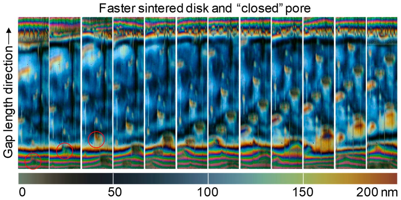
4.2.3. Faster Sintered Disk and “Closed” Pore
When the sintered disk has a higher velocity than the glass disk, the pores influence the lubricant film thickness opposite to the gap length direction. The “closed” pore marked in
Figure 14 emits a lubricant that moves at the mean lubricant speed, which is lower than the velocity of the sintered disk. This effect is positive just behind the dimple, however, on the side, the lubricant film thickness decreases. So, with respect to the total change in lubricant film thickness, the effect is rather neutral.
4.2.4. Faster Sintered Disk and “Open” Pore
When the sintered disk has a higher velocity than the glass disk, the effect of an “open” pore is negative, as can be seen from
Figure 15. The marked pore causes lubricant film breakdown in its shadow against the movement in gap length direction. It is apparent that the lubricant is also exhausted from a wider neighborhood of the pore in all directions.
During the test runs at the optical tribometer, another observation was also made; although the running time of the test runs was short and there was no lubricant film breakdown because of oil starvation, an increasing number of pores on the surface of the sintered specimen was apparent.
Figure 16 shows the interferograms of the EHL contact and corresponding light microscope images of the surface of one of the sintered disks at the beginning and after 15 and 60 min of testing. Surprisingly, there was almost no wear on the very thin chromium layer of the glass disk.
5. Discussion
The experimental results from the twin-disk test rig in
Section 4.1 showed, for the FVA3 and ground–polished disk pairings, unstable, metastable, and stable operating behaviors. For the polished–polished disk pairings, no unstable operating behavior was found. This may be mainly traced back to the much smaller surface roughness. However, for ground–polished and polished–polished disk pairings, the results with FVA3+PD showed very similar stable operating behaviors. The polished–polished disk pairings only reached a higher number of load cycles until the test runs were stopped because of the high coefficients of friction. The more uniform occurrence of stable operating conditions with FVA3+PD are traced back to the PD-additive forming tribofilms in mixed lubrication regimes that reduce the solid coefficient of friction significantly (Emrich et al. [
41]; Lohner et al. [
33]). This “stabilizes” the operating behavior until the additive is exhausted. The higher number of load cycles of polished–polished disk pairings are likely due to the slower exhaustion of the PD-additive because of the lower surface roughness.
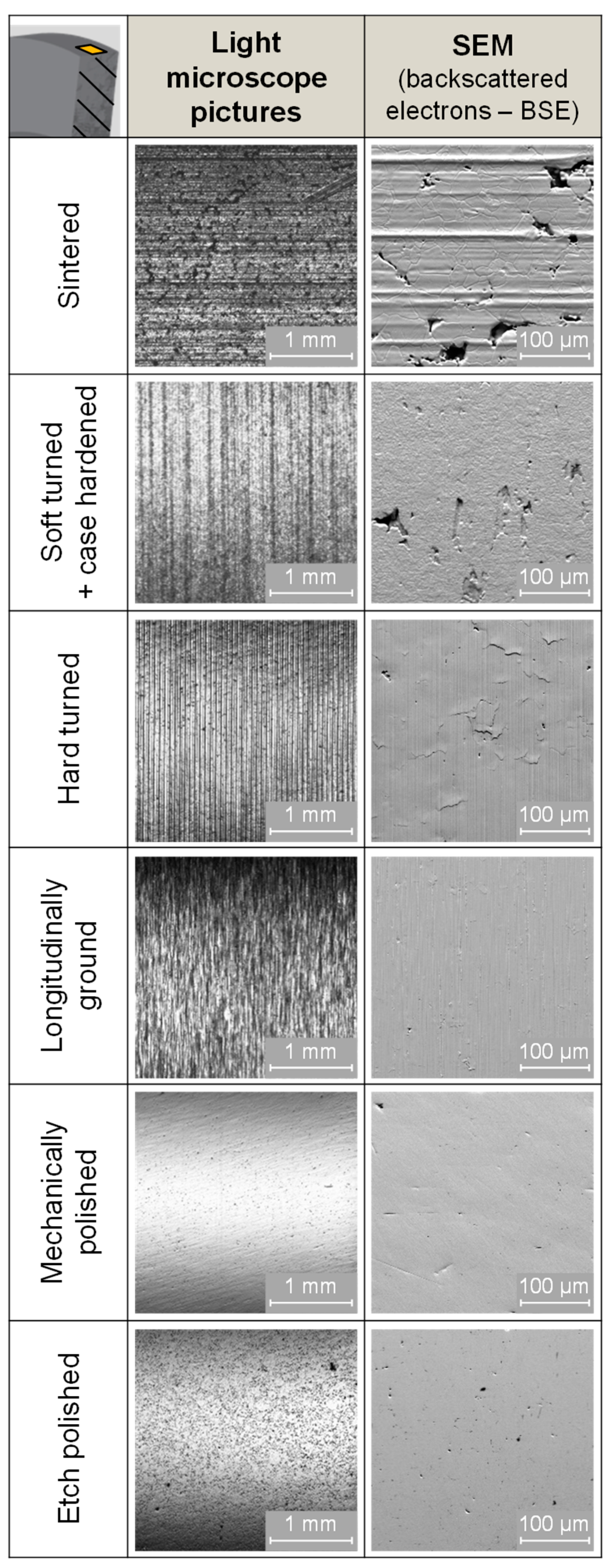
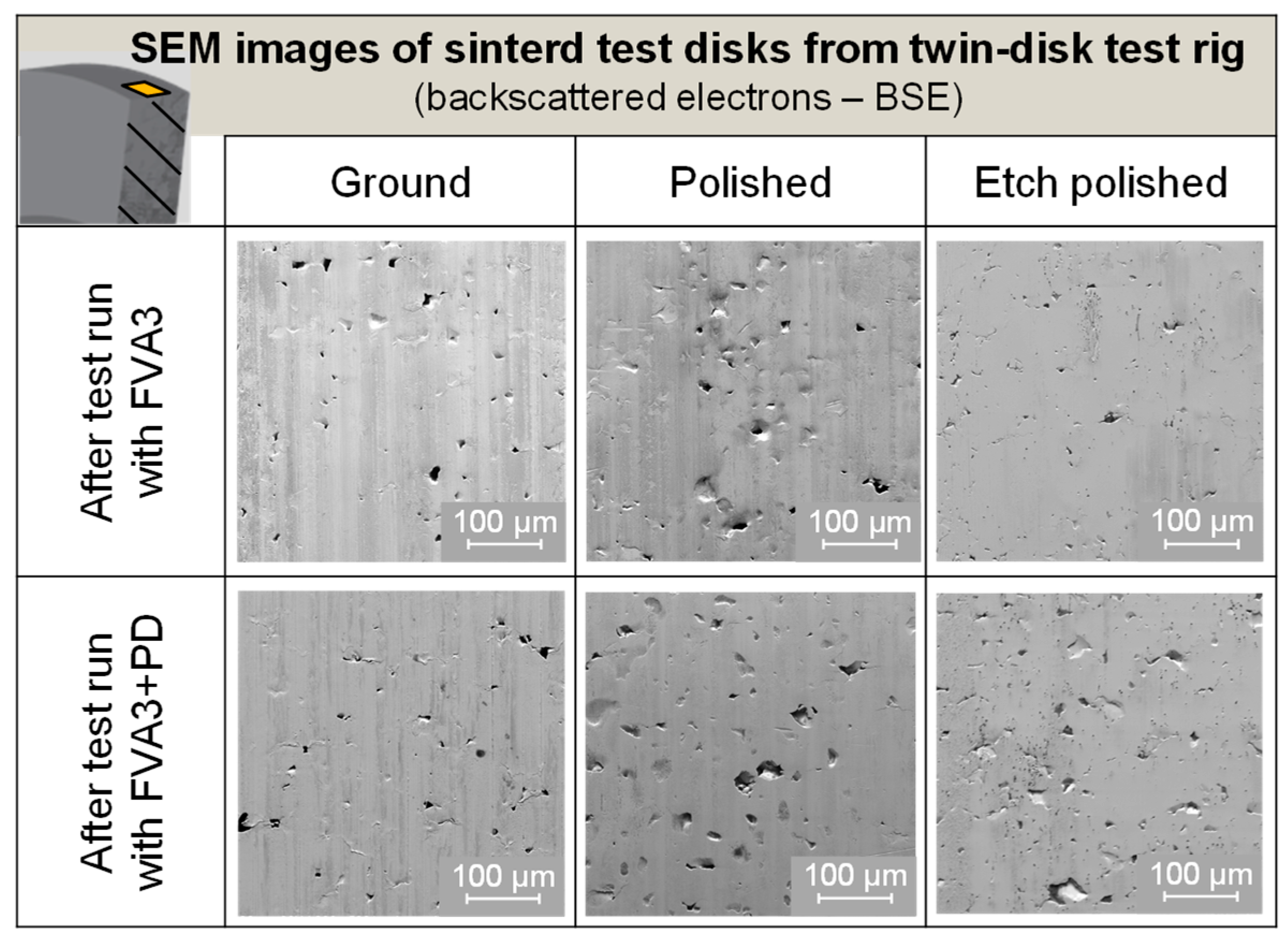
This indicates operation in mixed lubrication with solid contacts for all of the considered disk parings and lubricants at the twin-disk test rig. Thereby, mixed lubrication is expected to be less pronounced for the disk pairing of polished–polished compared to ground–polished. All of the sintered disks show a surface porosity with a higher number and size of pores after reaching the abortion criteria, compared with the documentation before the test run. This is shown in
Figure 17 by the representative SEM images of the sintered test disks, after the test runs at the twin-disk test rig stopped due to
ϑM2 > 150 °C. In comparison,
Figure 9 shows the representative SEM images of the ground–, polished–, and etch–polished surfaces of the sintered disks before the tests. The change in surface porosity is seen as being responsible for the limited endurance of the polished–polished and ground–polished disk pairings. This correlates to the test results with the etched–polished disk parings with a high number of pores even before the test run. In this case, all of the test runs show unstable operating behaviors with a very low number of load cycles for FVA3 and FVA3+PD.
Although a higher surface porosity can support the bleeding of the lubricant, it also strongly affects the EHL lubricant film, as shown by the results from the optical tribometer. Too many “open” pores can cause too many local film thickness breakdowns, resulting in direct solid contacts and the continuous stress and wear of the surface. To understand this in more detail, the results for “open” and “closed” pores for different kinematic conditions in
Section 4.2 are discussed in detail in the following.
Small “closed” pores can be interpreted as micro-dimples transiting through the contact. Therefore, a comparison with the effect of a single micro-dimple allows for a more precise description of the effect of “closed” pores on local lubricant film thickness.
Figure 18 and
Figure 19 show the passage of a single micro-dimple through a circular EHL contact. The specific operating conditions of the test are described in the literature [
25]. A dimple with a depth of 950 nm and a diameter of 45 μm was produced mechanically by a Rockwell indenter.
Figure 18 clearly shows that if the dimpled surface is faster, a local film thickness depression is formed in the inlet zone, which then transits through the EHL contact, followed by a local film thickness increase. This is due to lubricant flow from the dimple. With respect to the minimum film thickness, the effect is negative. If the dimpled surface is slower, as shown in
Figure 19, a negative inlet effect does not occur. The minimum film thickness occurs just behind the dimple when leaving the EHL contact.
The quantitative variation of the lubricant film thickness at various cross-sections in comparison to a surface with and without micro-dimple is shown in
Figure 20. If the dimpled surface is slower, the overall effect is negligible and the dimple causes only a redistribution of the lubricant in its vicinity. On the other hand, if the dimpled surface is faster, an overall film thickness increase occurs. Under these conditions, the average increase is approximately 10 nm in longitudinal direction. These conclusions on lubricant film thickness can also be qualitatively transferred to the local effect of a porous surface with “closed” pores.
There is also an important effect of the size of dimples, as indicated in
Figure 21. For smaller dimples obtained by a smaller indentation depth, the negative inlet effect disappears when the dimpled surface moves slower.
As an analogy for “closed” pores, the discussion on the effect of micro-dimples on the EHL contact shows that “open” pores, which are connected to the porous bulk structure, are much more serious, as they cause local lubricant film breakdown, no matter which surface moves. The explanation relates to the pressure gradient occurring as a result of “open” pores. Once an “open” pore enters the EHL contact, high pressure forces the lubricant to flow into the “open” pore.
Hence, exceeding a critical number of “open” pores is the main reason that sintered disks with a high surface porosity lead to unstable operating behavior at the twin-disk test rig. For etched–polished disk parings, this critical number of “open” pores is already exceeded after the surface finish, hence, all of the test runs show an unstable operating condition.
The optimal number of “open” pores can be defined as enough “open” pores to provide lubricant flow for self-lubrication, but too little to affect the EHL lubricant film too much by local disturbances. This balance seems to be approached by ground–polished disk pairings because of the smearing-up of pores during grinding, which results in a much smaller surface porosity of only
= 0.19%. However, it seems that the mechanical strength of the smeared-up “open” pores is not sufficient to reliably maintain the number of pores below a critical number of “open” pores. Once the opening of more pores is initiated, more lubricant breakdowns occur and breakdown also severity increases (
Figure 21). This results in wear phenomena, opening even more smeared up pores, which accelerates the increase in friction and temperature. Depending on the time sequence of this process, unstable, metastable, and stable operating behavior occurs. In case of polished–polished disk pairings, the operating behavior seems to be more stable because of the lower surface roughness.
In the optical measurements in
Figure 16, an increasing surface porosity was observed even under good lubrication conditions. The surface porosity increased during the running time, without significant wear of the counter body. This again indicates that the mechanical strength of the smeared-up pores is not enough to reliably maintain the number of “open” pores below a critical number of “open” pores. Because of the high tribological stress, the smeared up pores could be opened in a normal direction because of the pressure gradient between the contact and porous structure.
6. Summary and Conclusions
Previous studies on the intrinsic self-lubrication of oil-impregnated sintered materials in highly-loaded rolling-sliding contacts indicated a strong influence of surface porosity on lubricant film formation and operating behavior. In order to understand these relationships, this study investigated the effects of surface porosity in detail.
Different surface porosity conditions were manufactured by grinding, polishing, and etch-polishing. Extensive documentation was conducted using a light microscope, scanning electron microscopy, and X-ray computed tomography. The operating behaviors of oil-impregnated sintered materials with different surface porosities were investigated at a twin-disk test rig. The influence of the local effects of the surface porosity on the lubricant film in the elastohydrodynamically lubricated (EHL) contacts was investigated at an optical tribometer based on thin film colorimetric interferometry.
The results show that a high surface porosity results in many lubricant film breakdowns, and, hence, in unstable operating behaviors. Thereby, “open” pores connected to the porous bulk structure of the test disks are much more serious than “closed” pores. A grinding process smears-up pores on the surface and allows stable operating behaviors because of an optimal number of pores, so that the lubricant can bleed and the film formation is not disturbed too much. However, the mechanical strength of this lower permeable layer is not sufficient to reliably maintain the number of pores below a critical number of “open” pores.
The findings demand an appropriate surface finish technique to manufacture a low permeable layer with adequate mechanical strength so as to improve the operating behavior of oil-impregnated sintered materials in highly-loaded contacts. Therefore, further work will investigate the adequate surface compaction techniques.

 ,
, 


