Effect of Composite Bionic Micro-Texture on Cutting Performance of Tools

1
School of Mechanical and Vehicle Engineering, Changchun University, Changchun 130022, China
2
Technology Centre, CNAD Changchun Control Technology Co., Changchun 130102, China
*
Author to whom correspondence should be addressed.
Lubricants 2024, 12(1), 4; https://doi.org/10.3390/lubricants12010004
Submission received: 20 November 2023
/
Revised: 15 December 2023
/
Accepted: 19 December 2023
/
Published: 22 December 2023
(This article belongs to the Special Issue Friction and Wear of Cutting Tools and Cutting Tool Materials)
Abstract
:Dry cutting is an effective method to realize the concept of green cutting today. However, in the process of cutting bearing steel, the high temperatures and high pressures produced by the cutting tool and chip under dry friction seriously affect the machining performance of the tool. Therefore, a bionic microstructure tool based on bionics is proposed to improve the cutting performance and reduce friction by changing the size parameters of the microstructure. On the basis of finite element simulation and cutting tests, the cutting force, surface roughness, and chip shape are used to evaluate the cutting performance. It is found that composite bionic micro-textured tools have a significantly reduced cutting force compared with non-micro-textured tools; composite bionic micro-textured tools lead to a reduction in surface roughness of 10–25%; and composite bionic micro-textured tools are more prone to enhancing the curling and breaking of chips. In addition, with the increase in the microstructure area occupancy, the cutting performance of the tool was also significantly improved. Moreover, it was found that the cutting performance of the tool was improved when the area occupancy of the micro-texture on the front face of the tool was increased.
1. Introduction
Cutting-edge technology, known for its accuracy, high efficiency, affordability, and reliability, finds extensive applications in sectors like aerospace, energy, automotive, and defense, establishing itself as a key component in the primary technology sector of advanced manufacturing [1,2]. CBN (Cubic Boron Nitride) tools are widely used in cutting difficult-to-machine materials due to characteristics such as ultra-high hardness and chemical stability at high temperatures [3,4]. However, with the rising speed of machining, the wear, bonding, and chipping of the tool at high temperatures and high pressures seriously affect the accuracy of the product. Therefore, the question of how to extend tool life and improve machining accuracy has become a hot issue in today’s research [5].
The theory of friction reduction on non-smooth surfaces has gained a lot of attention in the manufacturing industry since the proposal of texturing the surface of the tool to extend tool life, reduce friction, and reduce cutting forces [6,7,8]. Khani, S, et al. studied the cutting of 7075 Aluminum Alloy with a micro-textured tool and found that the micro-textured tool was more efficient in comparison to the conventional tool, and the best cutting performance was achieved when the micro-texture width, depth, and edge pitch were 93.4 µm, 15 µm, and 50 µm, respectively [9]. Kümmel, J, et al. investigated the wear and tear of micro-textured carbide tools under dry cutting conditions and found that micro-textures with grooves on the tool’s front surface reduced chip tumor production during cutting and improved the surface quality of processed workpieces [10]. Salem, A, et al. investigated ways to improve the surface quality of the machined workpiece under dry cutting conditions by using micro-textures. The study found that when cutting AISI 10 steel at different cutting speeds, micro-textures on the tool’s surface reduced the length of contact between the tool and the chip, thus helping to reduce the cutting force and cutting heat [11]. Fouathiya et al. studied the micro-texturing of tools used to process titanium alloys and found that micro-texturing processes were more efficient during processing when microstructural types were crosslinked. It was found that the cutting forces, coefficient of friction, and tool wear generated by the tool were minimized when the micro-texture type was cross-micro-textured [12]. Therefore, it is particularly important to construct a suitable micro-texture on the tool surface for high-quality cutting. For the surface of the frictional contact sub-surface, most of the wear originates from abrasive and adhesive wear during the friction process. The micro-texture not only reduces friction but also accommodates abrasive particles and adhesion to improve the surface quality of the contact friction pair and reduce the wear rate. However, the surface structures of some organisms in nature show great potential for wear reduction and anti-wear effects; researchers have found that some animal body surfaces are not completely smooth but have certain geometric patterns of rows of tiny structural units, and these biological surfaces tend to have less friction. This discovery on the optimization of the cutting performance of the tool provides a new direction of research [13,14,15]. Yu, H, et al. found that a bionic tool alleviated the adhesion phenomenon and frictional wear of the tool in machining compared to a conventional tool [16]. Cui, X, et al. investigated the effect of micro-texturing of bionic multifunctional surfaces on the cutting performance of ceramic tools and found that micro-texturing could improve the impact resistance of the tool and allow it to store lubricating oil and promote lubrication spontaneously [17]. You, C, et al. designed a micro-texture based on the geometry of the head of the biological mantis and combined the micro-texture with the tool, finding that the bionic surface improved the cutting performance of the tool and decreased the cutting force under low-speed turning conditions [18]. Green manufacturing in the field of machining has become a research hotspot, but dry cutting conditions, due to the deterioration of the cutting conditions, will lead to increased tool wear, which seriously affects the machining accuracy, so the development of high-performance dry cutting tools is an effective way to improve cutting [19,20,21].
Previous studies have focused on optimizing the cutting performance of tools using the mechanism of action of micro-texturing to achieve a reduction in cutting forces and the extension of tool life, and despite the great potential of bionics, little mention has been made of bionics in the design and fabrication of micro-textures on tool surfaces. By observing the structure distribution of pearlite on the surfaces of shells, three kinds of micro-textured CBN tools were extracted and designed. The influence of the micro-textured structures on the cutting performance of the tool’s front surface on bearing steel was studied. The proposed micro-textured biomimetic tool has the functions of impact resistance, cutting force generation, storage of solid lubricant, and self-lubrication of expelled chips. Firstly, the influence of three biomimetic micro-textured materials on stress, cutting force, and cutting temperature was compared and analyzed through finite element simulation experiments, and the most optimal biomimetic micro-textured tool was selected. On the basis of this, laser machining was carried out for different morphologies of microstructure tools, and several cutting experiments were carried out. The cutting performance of bionic micro-textured tools was compared by using the cutting force, surface roughness, and chip shape as evaluation criteria.
2. Theoretical Models
2.1. Metal Cutting Theory
Metal cutting is the process of interaction between the tool and the workpiece in which the tool cuts off the excess layer of metal from the workpiece, during which cutting deformation occurs, chips are formed, and cutting forces, cutting heat, cutting temperatures, etc., are generated [22,23].
The relationship between the real contact area of elastic–plastic materials and the load can be expressed as Equation (1):
where FN is the load, Ar is the contact area, and σS is the compressive yield strength.
The formula for friction is shown in (2):
where Ff is the friction force; is the shear strength of the contact at the bonding point; and Ar is the contact area of the bonding point.
From the aforementioned Equations, it is evident that altering the contact area during metal cutting machining directly impacts the load and the friction’s intensity; thus, the micro-texture formation on the tool’s front side can alter the friction condition between the tool and the chip.
Substituting Equations (1) and (2) into Equation (3) yields an expression for the coefficient of friction:
Consequently, based on the equation, friction correlates with the load in cases where the workpiece’s material is definite. Consequently, altering the proximity zone between the tool and the workpiece can potentially reduce the creation of cutting forces. The process of the micro-textured tool’s action is depicted in Figure 1.
The diagram illustrates that the actual length of contact between the tool and the workpiece is determined by an equation when the micro-textured design is assembled on the tool’s front:
where L is the micro-textured tool contact length; LS is the actual cutting length; n is the number of micro-textures; and M is the micro-texture width.
So, the actual contact area of the micro-textured tool with the workpiece is represented by Equation (5):
where W is the cutting width; L is the cutting length.
Consequently, theoretical evaluations in crafting the micro-texture framework suggest that the dimensions of the micro-textured structure at the tool’s front significantly impact its cutting efficacy.
2.2. Sources of Biomimetic Micro-Textures
The dimensions and form of the micro-texture formations in the tool’s frontal working zone directly affect its wear, and especially when the micro-textured structures’ size and form are impractical, attaining friction reduction proves challenging, potentially worsening the tool’s wear and diminishing the workpiece’s surface quality post-machining. Bionics analysis revealed that the perlite structure on the shell’s surface is calcium-based, enabling it to evade marine predators from encroaching on it. The unique, consistent configuration of the surface perlite exhibits distinct mechanical characteristics, demonstrating resilience to external pressures, and the buffering impact on certain geological stresses is notably effective [24,25]. The surface configuration of the shell is depicted in Figure 2. Consequently, two varieties of micro-textures, namely, rectangular and curved, were derived from the shell’s surface design and applied to the tool’s front to enhance its cutting efficiency. The shapes of the micro-textures are shown in Figure 2a,b.
3. Finite Element Simulation Experiments of Bionic Micro-Textured Tools
Notable variations exist in the tool design and the materials used in diverse operational scenarios. Consequently, the bonding, deterioration, and frictional properties of tools used for slicing various materials vary [26,27,28,29,30]. Taking these elements into account, the surfaces of tools ought to possess attributes like enhanced impact resistance and encourage the movement of chips.
3.1. Three-Dimensional Modeling
At the forefront of the tool, two types of micro-texturing forms (parallel and arcuate grooves) were fashioned from the top shell surface, and the 3D modeling software developed three distinct micro-texturing instruments, as shown in Figure 3. The H tool (a curved micro-texturing tool), the P tool (a grooved micro-texturing tool), and the Z tool (a composite micro-texturing tool) symbolize a mix of curved and grooved shapes. The characteristics of the three micro-textured shapes are as follows: the dimensions of the micro-texture are 200 μm in spacing, 50 μm in width, 1200 μm in length, and 70 μm in depth.
3.2. Bionic Micro-Texture Finite Element Simulation Experiment
The crafted three-dimensional bionic instrument was integrated into the finite element simulation software, where the tool’s and workpiece’s meshes were segmented. The tool’s largest mesh dimension was set at 0.1 mm, and micro-textured components were segmented into finer mesh dimensions, with the smallest mesh size set at 0.01 mm; the largest mesh size was set at 3 mm for the workpiece, and the smallest was set at 0.01 mm. In the process of cutting, the tool’s circular movement in relation to the workpiece leads to significant friction between the tool’s tip and the material of the workpiece. During the cutting phase, the cutting instrument rotates in a circular path in relation to the workpiece. The tool’s tip makes direct contact with the material of the workpiece, creating significant friction that leads to cutting forces and heat. To achieve more precise simulation outcomes, the space surrounding the tool’s tip was characterized by an extremely accurate mesh. The material of the workpiece was identified as bearing steel; it was a round bar that measured 30 mm in diameter and 6 mm in thickness. The material used for the tool was CBN (Cubic Boron Nitride), the starting environmental temperature was set at 20 °C, and the simulation duration involved rotating the tool for one week in relation to the workpiece. During machining, the impact of the friction cutting force and cutting heat is substantial. Nonetheless, the way in which the cutting tool and workpiece interact, shaped by the process of cutting, results in a variety of phenomena. Through the analysis of relevant data, the friction coefficient was modified to 0.4, as depicted in the tool–workpiece finite element simulation mesh model in Figure 4.
In the realm of metal cutting simulations, the material constitutive model is crucial, and the Power-Law and User-Defined Yield Surface constitutive models are primarily utilized. The document opts for the User-Defined Yield Surface model, which details the transition of materials from elastic to plastic properties in certain strain conditions. This study employed the selected material’s Johnson–Cook model, which is adept at simulating strain hardening and thermal softening at various stages of cutting collisions and mirroring the actual phenomena, making it prevalent in the cutting field [31,32].
In the context of the Johnson–Cook material model, the yield stress is characterized as follows:
where σ is plastic stress; A is the yield strength; B is the strain hardening constant; C is the strain rate strengthening coefficient; m is the thermal softening parameter; n is the strain hardening parameter; ε is the plastic strain, p is the plastic strain rate, 0 is the reference strain rate; t is the material dynamic temperature; t0 is the ambient reference temperature; and tm is the material melting point.
Table 1 displays the material characteristics of bearing steel, while Table 2 presents the thermophysical properties and the modulus of elasticity parameters of the material.
To investigate the impact of cutting parameters on the forces generated in the process, finite element simulation experiments were performed on three preexisting bionic micro-textured tool models and a collection of micro-textured-free tools for external experimentation, with a cutting dosage of n = 1250 rpm, f = 0.15 mm/r, and ap = 0.2 mm.
3.3. Experimental Results and Analyses
The results of the finite element simulation of data collection are illustrated in Figure 5, which shows the cutting force fluctuation during the microtome tool’s cutting process, and the fluctuation map after noise reduction via processing filtering is also depicted in Figure 5’s micro-textured tool cutting force fluctuation map. The illustration shows that when the tool first touches the workpiece, there is a rapid escalation in the cutting force. As the tool’s processing progresses into the workpiece material, collisions with the cutting layer’s tip and the cutting force escalate significantly. As the material of the workpiece undergoes shear failure due to equivalent plastic strain, causing it to break again, the metal’s cutting layer and the substrate of the workpiece separate, leading to a reduction in the primary cutting force to a stable level, where the value of the cutting force generally stabilizes.
3.3.1. Impact of Micro-Textured Material on Cutting Forces
In Figure 6a, the outcomes of the cutting force simulation for steel bearing cuts using four varieties of CBN tools are depicted. From the figure, it can be seen that when the spindle speed n = 1250 rpm, the cutting forces of the three kinds of micro-textured structure tools, compared to the traditional tool, were reduced by 10.4%, 12.8%, and 19.2%, of which the Z tool prompted the most significant reduction in the cutting force effect. The reason lies in the micro-textured nature of the tool’s front surface, which diminishes the contact area between the tool and the workpiece and lowers the friction coefficient, thereby lessening the cutting force. To verify the simulation’s accuracy, which expanded the experimental group, cutting experiments were performed at speeds of 800 and 1000 rpm, with the results showing the Z tool’s ability to decrease the cutting force by 22% and 21.18% at 800 rpm and 1000 rpm, respectively. This demonstrates the potential of the composite bionic micro-weave device to improve the minimization of the cutting force.
3.3.2. Impact of Micro-Textured Surfaces on Stress Levels
Figure 7 illustrates the stress profiles of the four types of tools juxtaposed with non-micro-textured tools. H, P, and Z show stress diminution rates of 8.6%, 7.5%, and 15.22%, respectively, underscoring the critical role of composite biomimetic micro-textured tools in stress absorption. In the process of cutting with the four types of tools, especially those lacking micro-textures, a consistent advancement in the cutting method is observed, starting at the tip of the tool and gradually increasing to the internal cutting stress level; in the case of bionic micro-textured tools, stress slowly permeated the micro-textured sections near the tool’s tip, accumulating predominantly in the micro-textured areas distant from the tool’s location. Regarding the Z tool, the stress distribution within its interior was quicker compared to the other two tools.
3.3.3. Impact of Micro-Textures on the Temperature at Which Cutting Occurs
Information regarding the cutting temperature at the tip of the tool was collected, and Figure 8 visually depicts how the micro-textured structure tool affects this temperature. The illustration reveals that at an identical spindle velocity, the bionic micro-textured tool’s heat dissipation efficiency markedly surpasses that of the non-micro-textured tool, where the Z tool’s cutting temperature drops by 11.32%. The micro-textured nature of the tool’s front surface enhances the frictional heat produced by the friction between the tool and the chip; conversely, the presence of a micro-textured material lessens the cutting force from the tool’s direct interaction with the workpiece material, thereby decreasing the plastic deformation in the workpiece material’s cutting layer, leading to a decrease in the temperature needed for cutting. The Z tool, having a lower overall cutting force than the other micro-textured tools, results in lower cutting heat generation.
In Figure 9, it is observed that the tool’s cutting heat primarily accumulates on the tool tip’s front surface and the workpiece, facilitating the removal of material layers in close proximity to the tool’s components, particularly for the bionic micro-textured tool. The micro-textured nature of the tool’s surface results in an expanded heat dissipation area and a reduced cutting temperature.
Simulated tests on bionic micro-textured instruments demonstrate their superiority over the other three in terms of cutting force, stress distribution, and temperature, establishing a theoretical basis for the subsequent bionic micro-textured cutting experiments.
4. Bionic Micro-Textured Tool Cutting Experiments
4.1. Composite Biomimetic Micro-Textured Tool Preparation
The laser processing method has the advantages of high energy density, good processing controllability, fast processing speed, and easy-to-achieve precision processing. Therefore, in this study, the laser processing method was used to prepare the surface micro-texture of the tool. The default parameters were selected to process the tool, and the cutting performance of the Z tool was found to be superior through the above simulation experiments, so the composite biomimetic micro-texture of the Z tool was investigated in depth. Z tools (named Z1, Z2, and Z3, respectively) with spacings of 150 µm, 200 µm, and 250 µm were constructed using a laser machining method, as shown in Figure 10.
When utilizing laser machining on the tool’s front, the debris produced is prone to melting on its micro-textured surfaces; thus, the laser-marked blade was placed in an ethanol ultrasonic bath and vibrated for thirty minutes to eliminate contaminants from the tool’s exterior. Table 3 presents the characteristics of the micro-texture dimensions. On the basis of the micro-texture data in Table 3, the micro-textured samples were prepared, as illustrated in Figure 11.
4.2. Bionic Micro-Textured Tool Cutting Laboratory
Furthermore, to confirm the outcomes of the cutting simulation tests, CBN tool cutting experiments on bearing steel were conducted under identical cutting conditions. The object of study was a workpiece made of bearing steel in the shape of a round bar with a diameter of 50 mm and a length of 200 mm; both ends were machined to produce top holes, and the surface was pre-turned. The chemical composition of GCr15, a widely utilized type of bearing steel known for its excellent tool characteristics and mechanical stability, is detailed in Table 4 below. The cutting tool material was CBN. A CBN cutting tool is used in the cutting of ferrous metals when the chemical stability is very strong; its hardness is second only to that of a diamond tool, and it is considered a super-hard tool (brand CNGA120404-4N, Manufacturer Funek, Origin Henan, China, tool front angle Y = −6°). The CA6140 standard lathe was chosen, and the tool was fitted into a Kistler 9527B type tool holder to measure the cutting force in three directions utilizing the ZT-Y-50W laser marking machine (Manufacturer Shanghai Sanko, Place of Origin Shanghai, China) The Leica DVM250 super-depth-of-field microscope (Supplier Leica Microsystems, Shanghai, China) was employed to scrutinize and examine the wear patterns of the chips and tools. The experimental timetable is displayed in Table 5, while Figure 12 illustrates the necessary cutting tests for the experimental setup.
4.3. Experimental Results and Analysis
4.3.1. Impact of Combined Bionic Micro-Texture Elements on Slicing Forces
Figure 13 depicts the cutting forces generated by the four tools at different cutting speeds. The depiction shows that at n = 1250 rpm, the slicing power of the composite bionic micro-textured instrument is significantly lower compared to the non-micro-textured one, resulting in enhanced uniformity in the simulation. Usually, under dry friction conditions, the main source of the cutting force stems from the distortion of the material’s cutting layer and the resulting staining effect. In the case of the composite bionic micro-textured instrument, diminishing the tool’s size and the chip’s proximity results in decreased friction, thereby lowering the cutting force; conversely, this also affects the cutting procedure. The micro-textured segment of the chip held on the tool’s front will be captured and preserved within the micro-textured interior, which acts as a storage unit for the chip, preventing staining from knives. This research revealed a 26.08% reduction in the cutting power of the Z3 tool relative to the non-micro-textured tool, markedly outperforming the other two composite bionic micro-textured tools. This is due to the Z3 tool’s front having a more extensive micro-textured surface compared to the other two types of tools, leading to an expanded micro-textured area that minimizes the contact area between the tool and the workpiece material, thereby reducing friction in the Z3 tool and reducing the cutting force. Figure 14 shows the graph of the total area of the micro-texture.
Figure 15 illustrates how the parameters of the composite bionic micro-textured structure affect the cutting force at different speeds, showing a steady decrease in the cutting force as the rotational speed lessens. When n = 800 rpm, the cutting force of the Z3 tool was reduced by 25.51% relative to the non-micro-textured structure tool; when n = 1000 rpm, the cutting force of the Z3 tool decreased by 28.03% in comparison to the non-micro-textured structure tool. With the reduction in speed, there is a decrease in the rate at which materials are removed per time unit, and as the deformation of the workpiece material lessens, the cutting force diminishes.
4.3.2. Impact of Combined Bionic Micro-Textured Factors on the Texture of Surface
Surface roughness is an important indicator for evaluating surface integrity and affects the service life of the workpiece. In this study, the surface quality of the workpiece after machining was observed with an optical microscope. Figure 16 shows the roughness data of the workpiece after machining with four types of tools at a spindle speed of 1250 rpm. From the figure, it can be seen that the average surface roughness of Sa decreases by 13.29%, 12.21%, and 23.26% when the Z1, Z2, and Z3 tools are used, compared to that obtained with the tool without micro-texture, and the root mean square height of the Z3 tool is 1.298 lower than that of the other three tools. This is because the micro-texture can store the tiny debris generated by friction, reducing the intermittent contact between the tool surface and debris; avoiding contact between the debris and the cutter surface in the machining process prevents the kind of extrusion caused by the tool surface wear, which affects the machining quality. With the increase in micro-texture spacing, the micro-textured area occupancy increases, and the ability to capture debris increases, contributing to the decline in the surface roughness of the workpiece.
A three-dimensional profilometer was employed to examine the workpiece’s surface roughness post-machining, and Figure 17 illustrates the three-dimensional structure of the workpiece’s surface following machining with four tools at an identical rotational velocity. The results reveal that the Z3 tool finalizes the machining process, and the tool’s smooth surface is observed to bear clear tool marks. The reason lies in the fact that the cutting force produced by the tool’s micro-textured structure is lower than that generated by a non-micro-textured structure, resulting in a micro-textured structure throughout the entire friction process, which in turn reduces friction and enhances its smoothness, and the stability of machine tool machining is enhanced.
4.3.3. Impact of Combined Biomimetic Micro-Textured Variables on Microchips
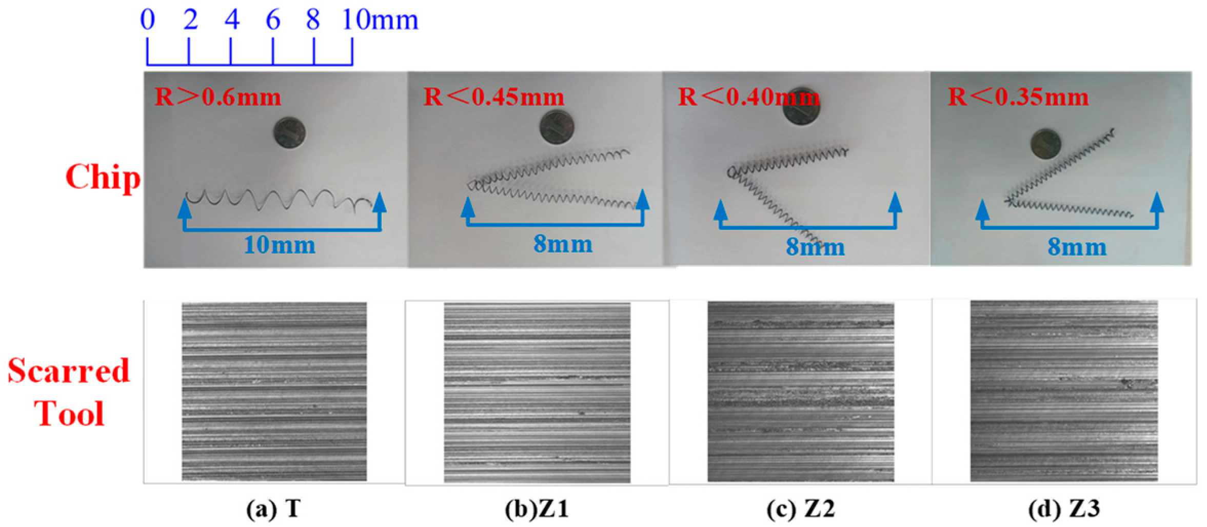
In the process of cutting, a chip that does not break becomes uncontrollable, significantly hindering the machine tool’s normal operation, causing damage to the tool, and changing the appearance of the processed product. This study revealed that using four different types of machining tools led to the development of four unique chip varieties, as depicted in Figure 18, and the surface of the workpiece following machining had a cutter mark topography. The diagram shows that when the T tool cuts into a stretched, ring-shaped spiral chip, the material of the workpiece continuously splits due to shear force, leading to the creation of chips along the outflow of the front face. When the chips are expelled during the collision of tool surface extrusions, they curl, resulting in the formation of curling strain inside the chip. The employment of a composite bionic micro-textured device leads to the formation of a short circular spiral chip characterized by a diminished circular radius. The resemblance of the tool’s micro-textured part to the chip-breaking groove’s design, along with the chip-breaking groove, leads to increased curling strain and a smaller curl radius, contributing to chip damage and leakage.
Differing from traditional tools, the micro-textured texture of the tool face facilitates the formation and storage of small chips within the micro-textured area while using the micro-textured cutting tool, thus averting severe wear due to the chip protruding between the tool face and the workpiece; this action results in the removal of the ultimate material. A micro-textured tool’s front, known for its heat dissipation properties, leads to a reduced cutting force, thereby decreasing the wear of the tool.
The previously mentioned slicing experiments demonstrate that composite bionic micro-textured instruments surpass non-micro-textured ones in efficiency by lessening the force needed for cutting and diminishing the surface roughness of the machined workpiece, promoting the deterioration of chips and improving the slicing efficiency; these effects are optimal with the Z3 tool.
5. Conclusions
This research was carried out to explore how the micro-texture size factor (measured as micro-texture spacing) influences the tool’s efficiency in slicing bearing steel with varying cutting settings. Drawing from bionic principles, this document introduces three varieties of bionic micro-textured structures: a curved bionic micro-textured tool, a parallel bionic micro-textured tool, and a composite bionic micro-textured tool. A multitude of finite element simulations and cutting tests were conducted to assess the micro-textured tool on the basis of the cutting force, temperature, chip bending radius, and surface texture, leading to the following findings:
1. Finite element simulation experiments reveal that the bionic micro-textured tool significantly outperforms the non-micro-textured tool in stress reduction. In the context of the cutting force and temperature, the composite bionic micro-textured tool enhances the cutting force to decrease by 19.2% and the cutting temperature to decrease by 11.32%.
2. The cutting tests revealed that the composite bionic micro-textured instrument successfully withstood impacts and lessened the tool–chip contact zone, and utilizing the micro-textured segment as the chip’s storage unit lessened the friction between the chip and the tool, leading to a 26.08% decrease in the cutting force and a 23.26% reduction in surface roughness.
3. The experimental findings indicate the consistent enhancement of the tool’s cutting efficiency as the proportion of its micro-textured area grows.
4. Demonstrations reveal that employing a composite bionic micro-textured instrument with a 300 µm micro-weave gap in bearing steel machining significantly enhances the tool’s cutting efficiency, laying a theoretical groundwork for future superior bearing steel machining and highlighting the potential of micro-weave tools for machining.
Author Contributions
Conceptualization, T.X.; writing—original draft, C.M.; methodology, H.S.; software, K.X. and J.L.; review and editing, Q.L. All authors have read and agreed to the published version of the manuscript.
Funding
Jilin Provincial Department of Education “JJKH20240738KJ”.
Data Availability Statement
Data will be made available on request.
Acknowledgments
The authors would like to thank the members of the project team for their dedication and effort and the teachers and schools for their help.
Conflicts of Interest
The authors declare no conflicts of interest.
References
- Fabián Pérez-Salinas, C.; Fernández-Lucio, P.; del Olmo, A.; Aldekoa-Gallarza, I.; Norberto López de Lacalle, L. The influence of cutting edge microgeometry on the broaching of Inconel 718 slots. Eng. Sci. Technol. Int. J. 2023, 48, 101563. [Google Scholar] [CrossRef]
- Ghosh, S.; Rao, P.V. Application of sustainable techniques in metal cutting for enhanced machinability: A review. J. Clean. Prod. 2015, 100, 17–34. [Google Scholar]
- Aouici, H.; Yallese, M.A.; Chaoui, K.; Mabrouki, T.; Rigal, J.F. Analysis of surface roughness and cutting force components in hard turning with CBN tool: Prediction model and cutting conditions optimization. Measurement 2012, 45, 344–353. [Google Scholar] [CrossRef]
- Liu, K.; Li, X.P.; Rahman, M.; Liu, X.D. CBN tool wear in ductile cutting of tungsten carbide. Wear 2003, 255, 1344–1351. [Google Scholar] [CrossRef]
- Stephenson, D.A.; Agapiou, J.S. Metal Cutting Theory and Practice; CRC Press: Boca Raton, FL, USA, 2018. [Google Scholar]
- Li, B. A review of tool wear estimation using theoretical analysis and numerical simulation technologies. Int. J. Refract. Met. Hard Mater. 2012, 35, 143–151. [Google Scholar] [CrossRef]
- Iliescu DM, F.D.; Gehin, D.; Gutierrez, M.E.; Girot, F. Modeling and tool wear in drilling of CFRP. Int. J. Mach. Tools Manuf. 2010, 50, 204–213. [Google Scholar] [CrossRef]
- Patel, D.S.; Jain, V.K.; Shrivastava, A.; Ramkumar, J. Electrochemical micro texturing on flat and curved surfaces: Simulation and experiments. Int. J. Adv. Manuf. Technol. 2019, 100, 1269–1286. [Google Scholar] [CrossRef]
- Khani, S.; Razfar, M.R.; Haghighi, S.S.; Farahnakian, M. Optimization of micro-textured tools parameters in thread turning process of aluminum 7075 aerospace alloy. Mater. Manuf. Process. 2020, 35, 1330–1338. [Google Scholar] [CrossRef]
- Kümmel, J.; Braun, D.; Gibmeier, J.; Schneider, J.; Greiner, C.; Schulze, V.; Wanner, A. Study on micro texturing of uncoated cemented carbide cutting tools for wear improvement and built-up edge stabilisation. J. Mater. Process. Technol. 2015, 215, 62–70. [Google Scholar] [CrossRef]
- Ellersiek, L.; Menze, C.; Sauer, F.; Denkena, B.; Möhring, H.C.; Schulze, V. Evaluation of methods for measuring tool-chip contact length in wet machining using different approaches (micro-textured tool, in-situ visualization and restricted contact tool). Prod. Eng. 2022, 16, 635–646. [Google Scholar] [CrossRef]
- Fouathiya, A.; Meziani, S.; Sahli, M.; Barrière, T. Experimental investigation of micro-textured cutting tool performance in titanium alloy via turning. J. Manuf. Process. 2021, 69, 33–46. [Google Scholar] [CrossRef]
- Du, H.Y.; He, L.; Du, H.S.; Ma, K.J.; Li, Y.P. Bionic tribological tool weaving design. Comb. Mach. Tools Autom. Mach. Technol. 2016, 506, 138–142. [Google Scholar] [CrossRef]
- You, C.; Xie, C.; Chu, X.; Zhou, W.; Zhao, G.; Lian, Y. Cutting performance of bionic cutting tools based on surface microstructures of blood clam Tegillarca granosa in dry cutting of CFRP. Int. J. Adv. Manuf. Technol. 2022, 119, 2961–2969. [Google Scholar] [CrossRef]
- Neugebauer, R.; Drossel, W.G.; Ihlenfeldt, S.; Harzbecker, C. Design method for machine tools with bionic inspired kinematics. CIRP Ann. 2009, 58, 371–374. [Google Scholar] [CrossRef]
- Yu, H.; Han, Z.; Zhang, J.; Zhang, S. Bionic design of tools in cutting: Reducing adhesion, abrasion or friction. Wear 2021, 482, 203955. [Google Scholar] [CrossRef]
- Cui, X.; Duan, S.; Guo, J.; Ming, P. Bionic multifunctional surface microstructure for efficient improvement of tool performance in green interrupted hard cutting. J. Mater. Process. Technol. 2022, 305, 117587. [Google Scholar] [CrossRef]
- You, C.; Zhao, G.; Chu, X.; Zhou, W.; Long, Y.; Lian, Y. Design, preparation and cutting performance of bionic cutting tools based on head microstructures of dung beetle. J. Manuf. Process. 2020, 58, 129–135. [Google Scholar] [CrossRef]
- Akhtar, S.S. A critical review on self-lubricating ceramic-composite cutting tools. Ceram. Int. 2021, 47, 20745–20767. [Google Scholar] [CrossRef]
- Wu, Z.; Deng, J.; Chen, Y.; Xing, Y.; Zhao, J. Performance of the self-lubricating textured tools in dry cutting of Ti-6Al-4V. Int. J. Adv. Manuf. Technol. 2012, 62, 943–951. [Google Scholar]
- Wu, Z.; Deng, J.; Su, C.; Luo, C.; Xia, D. Performance of the micro-texture self-lubricating and pulsating heat pipe self-cooling tools in dry cutting process. Int. J. Refract. Met. Hard Mater. 2014, 45, 238–248. [Google Scholar] [CrossRef]
- Qin, S.; Shi, X.; Xue, Y.; Zhang, K.; Huang, Q.; Wu, C.; Shu, J. Coupling effects of bionic textures with composite solid lubricants to improve tribological properties of TC4 alloy. Tribol. Int. 2022, 173, 107691. [Google Scholar] [CrossRef]
- Zheng, K.; Yang, F.; Pan, M.; Zhao, G.; Bian, D. Effect of surface line/regular hexagonal texture on tribological performance of cemented carbide tool for machining Ti-6Al-4V alloys. Int. J. Adv. Manuf. Technol. 2021, 116, 3149–3162. [Google Scholar] [CrossRef]
- Zhao, C.; Long, R.; Zhang, Y.; Wang, Y.; Wang, Y. Influence of characteristic parameters on the tribological properties of vein-bionic textured cylindrical roller thrust bearings. Tribol. Int. 2022, 175, 107861. [Google Scholar] [CrossRef]
- Liu, G.L.; Zheng, J.T.; Huang, C.Z.; Sun, S.F.; Liu, X.F.; Dai, L.J.; Wang, X.Y. Coupling effect of micro-textured tools and cooling conditions on the turning performance of aluminum alloy 6061. Adv. Manuf. 2023, 11, 663–681. [Google Scholar] [CrossRef]
- Yu, Q.; Zhang, X.; Miao, X.; Liu, X.; Zhang, L. Performances of concave and convex microtexture tools in turning of Ti6Al4V with lubrication. Int. J. Adv. Manuf. Technol. 2020, 109, 1071–1092. [Google Scholar] [CrossRef]
- Gajrani, K.K.; Sankar, M.R.; Dixit, U.S. Tribological performance of MoS2-filled microtextured cutting tools during dry sliding test. J. Tribol. 2018, 140, 021301. [Google Scholar] [CrossRef]
- Gao, G.; Wang, Y.; Fu, Z.; Zhao, C.; Xiang, D.; Zhao, B. Review of multi-dimensional ultrasonic vibration machining for aeronautical hard-to-cut materials. Int. J. Adv. Manuf. Technol. 2023, 124, 681–707. [Google Scholar] [CrossRef]
- Tapia, E.; Sastoque-Pinilla, L.; De Lacalle, N.L.; Lopez-Novoa, U. Towards real time monitoring of an aeronautical machining process using scalable technologies. In Proceedings of the 2022 7th International Conference on Smart and Sustainable Technologies (SpliTech), Split/Bol, Croatia, 5–8 July 2022; pp. 1–6. [Google Scholar]
- Cui, X.; Li, C.; Ding, W.; Chen, Y.; Mao, C.; Xu, X.; Liu, B.; Wang, D.; Li, H.N.; Zhang, Y.; et al. Minimum quantity lubrication machining of aeronautical materials using carbon group nanolubricant: From mechanisms to application. Chin. J. Aeronaut. 2022, 35, 85–112. [Google Scholar] [CrossRef]
- Pang, K.; Wang, D. Study on the performances of the drilling process of nickel-based superalloy Inconel 718 with differently micro-textured drilling tools. Int. J. Mech. Sci. 2020, 180, 105658. [Google Scholar] [CrossRef]
- Fan, L.; Deng, Z.L.; He, Y.; Zhu, X.L.; Gao, X.J.; Jin, Z. The effects of micro-texture shape on serrated chip geometry in the hardened steel AISI D2 cutting process. Surf. Topogr. Metrol. Prop. 2022, 10, 015031. [Google Scholar] [CrossRef]
Figure 1.
Mechanism of micro-textured tool.
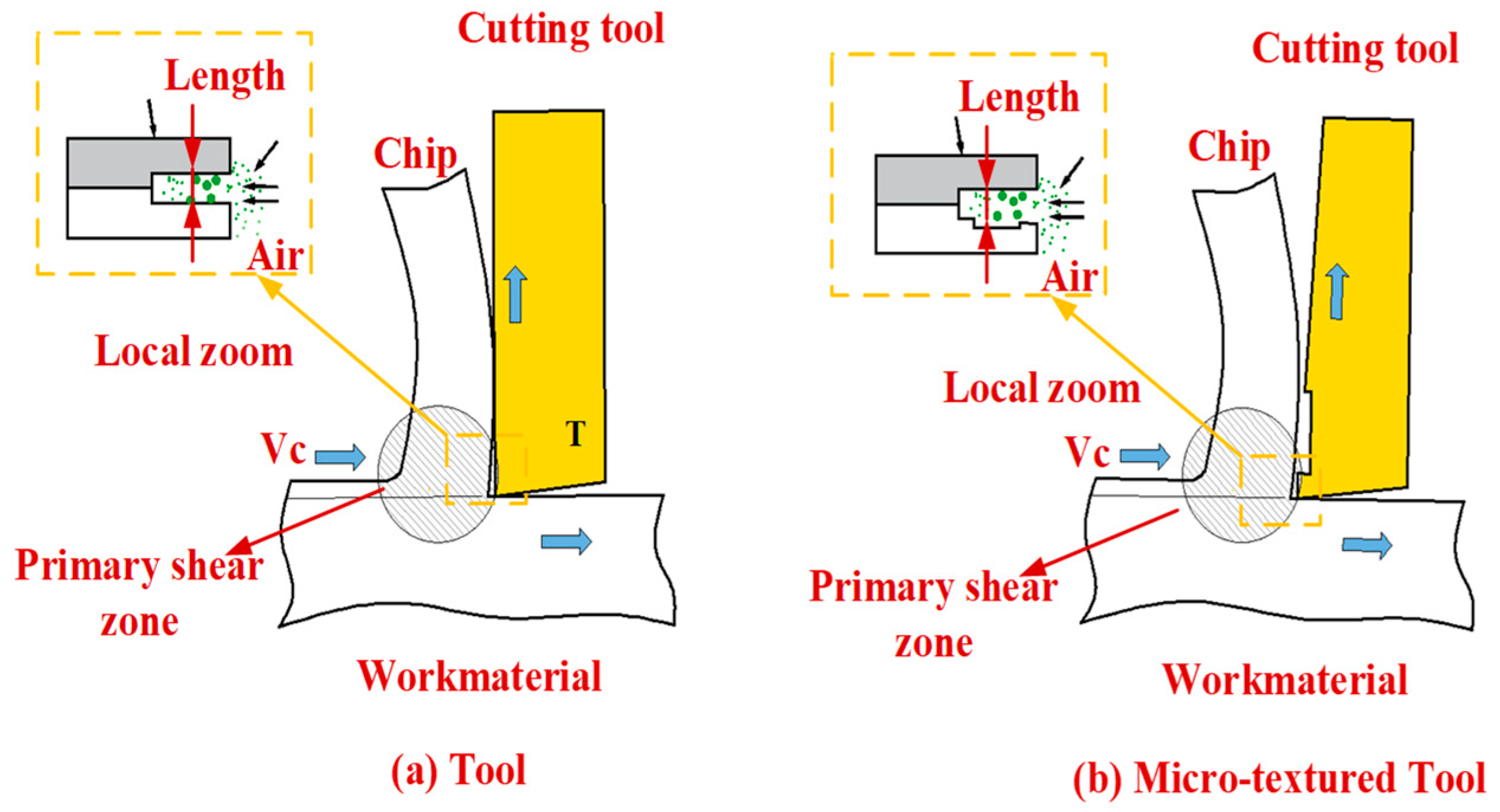
Figure 2.
Sources of bionic micro-textures.
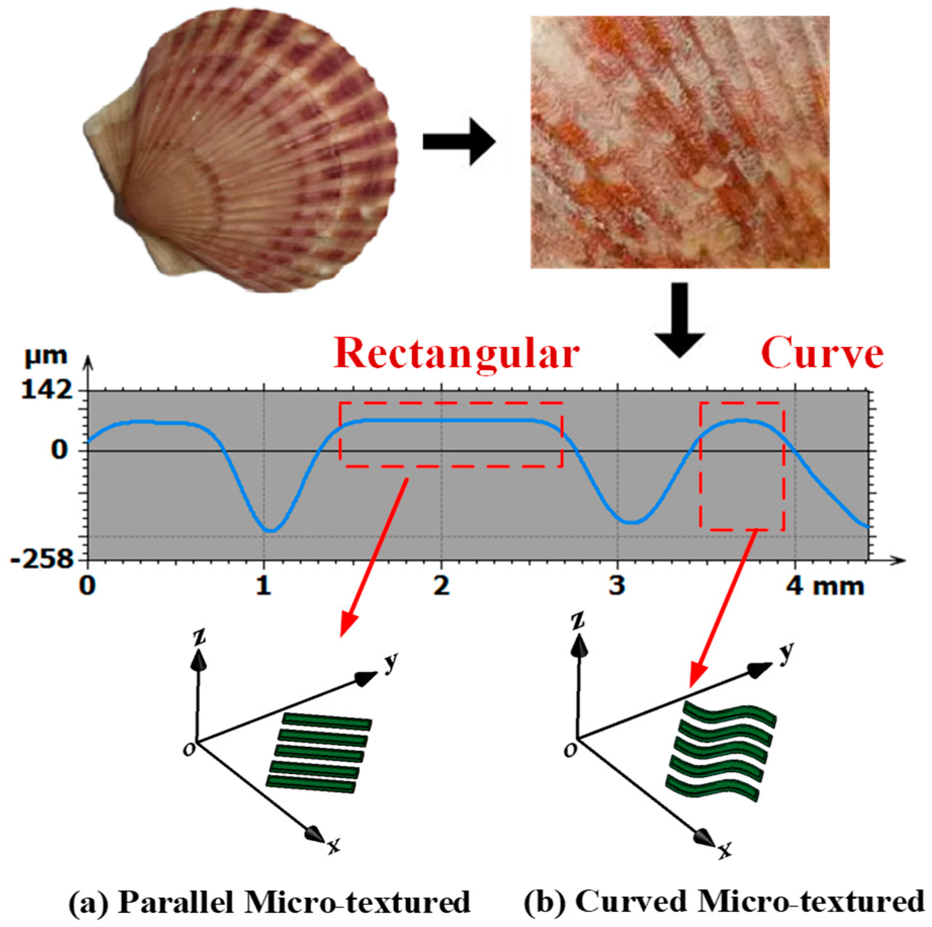
Figure 3.
Establishment of three-dimensional model of micro-textured tool.

Figure 4.
Workpiece–tool meshing. (a) Finite Element Simulation of Tool Cutting and Machining, (b) Partial enlargement of the front face, (c) Cutting track.
Figure 4.
Workpiece–tool meshing. (a) Finite Element Simulation of Tool Cutting and Machining, (b) Partial enlargement of the front face, (c) Cutting track.
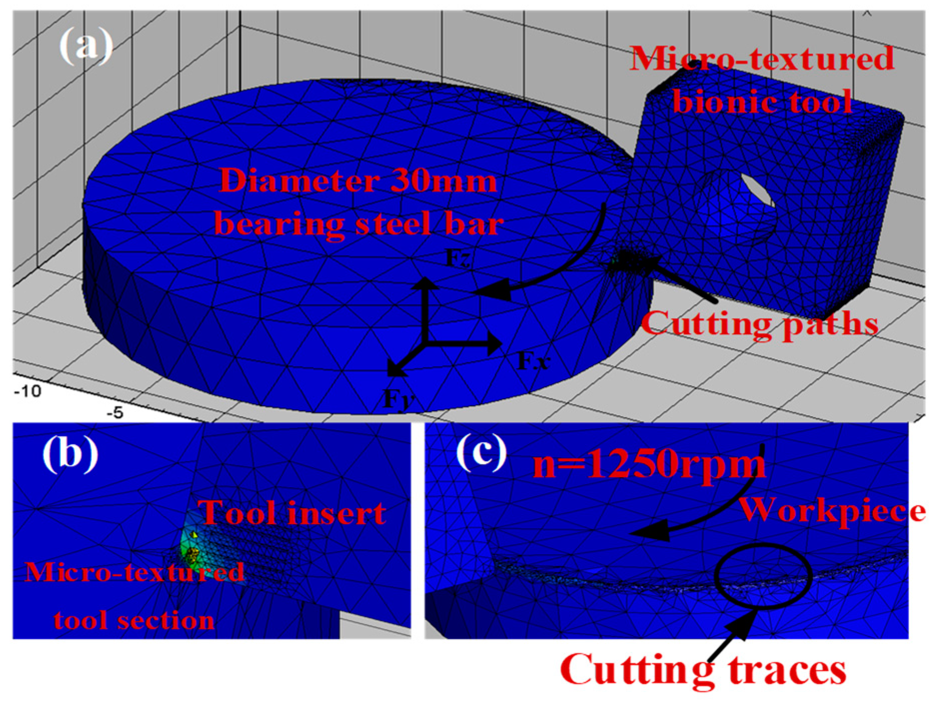
Figure 5.
Cutting force fluctuation diagram.
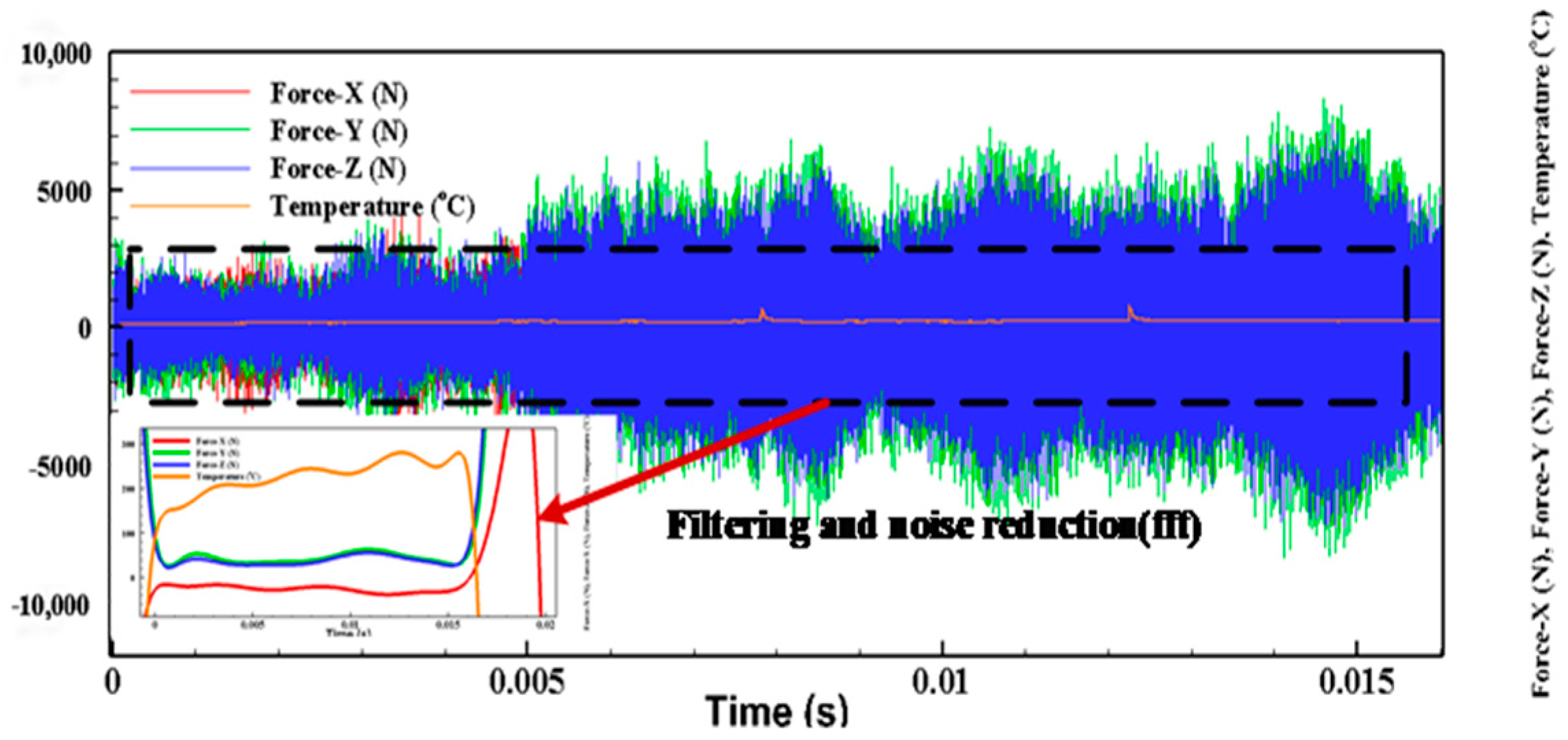
Figure 6.
Comparison of cutting forces of 4 kinds of tools. (a) The impact of micro-textured instruments on slicing forces at n = 1250 rpm. (b) The impact of micro-textured instruments on slicing forces at n = 1000 rpm. (c) The impact of micro-textured instruments on slicing forces at n = 800 rpm.
Figure 6.
Comparison of cutting forces of 4 kinds of tools. (a) The impact of micro-textured instruments on slicing forces at n = 1250 rpm. (b) The impact of micro-textured instruments on slicing forces at n = 1000 rpm. (c) The impact of micro-textured instruments on slicing forces at n = 800 rpm.
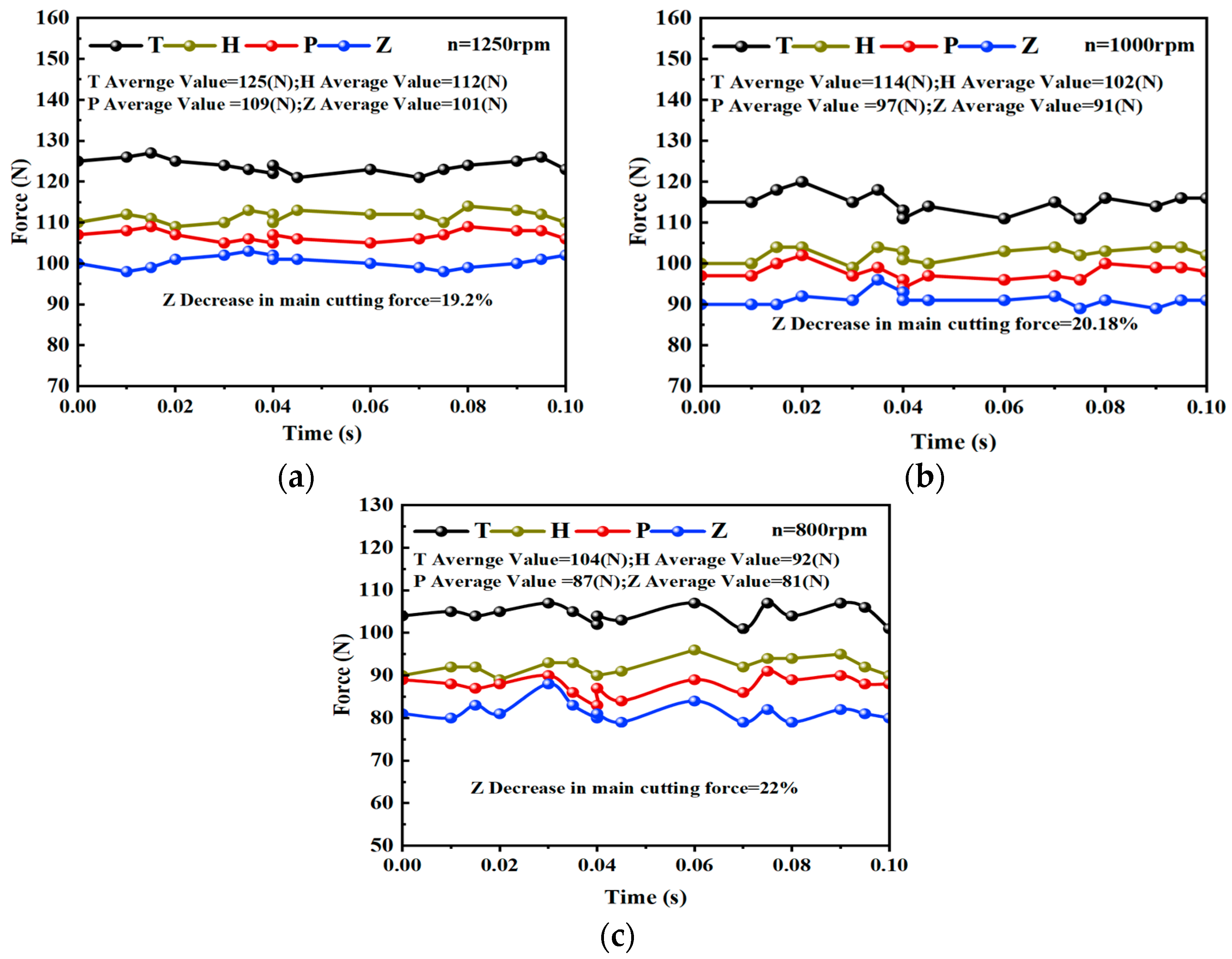
Figure 7.
Stress distribution of 4 kinds of tools (i–iii) are the number of simulation steps in the cutting process).
Figure 7.
Stress distribution of 4 kinds of tools (i–iii) are the number of simulation steps in the cutting process).

Figure 8.
Comparison of cutting temperatures of 4 kinds of tools.
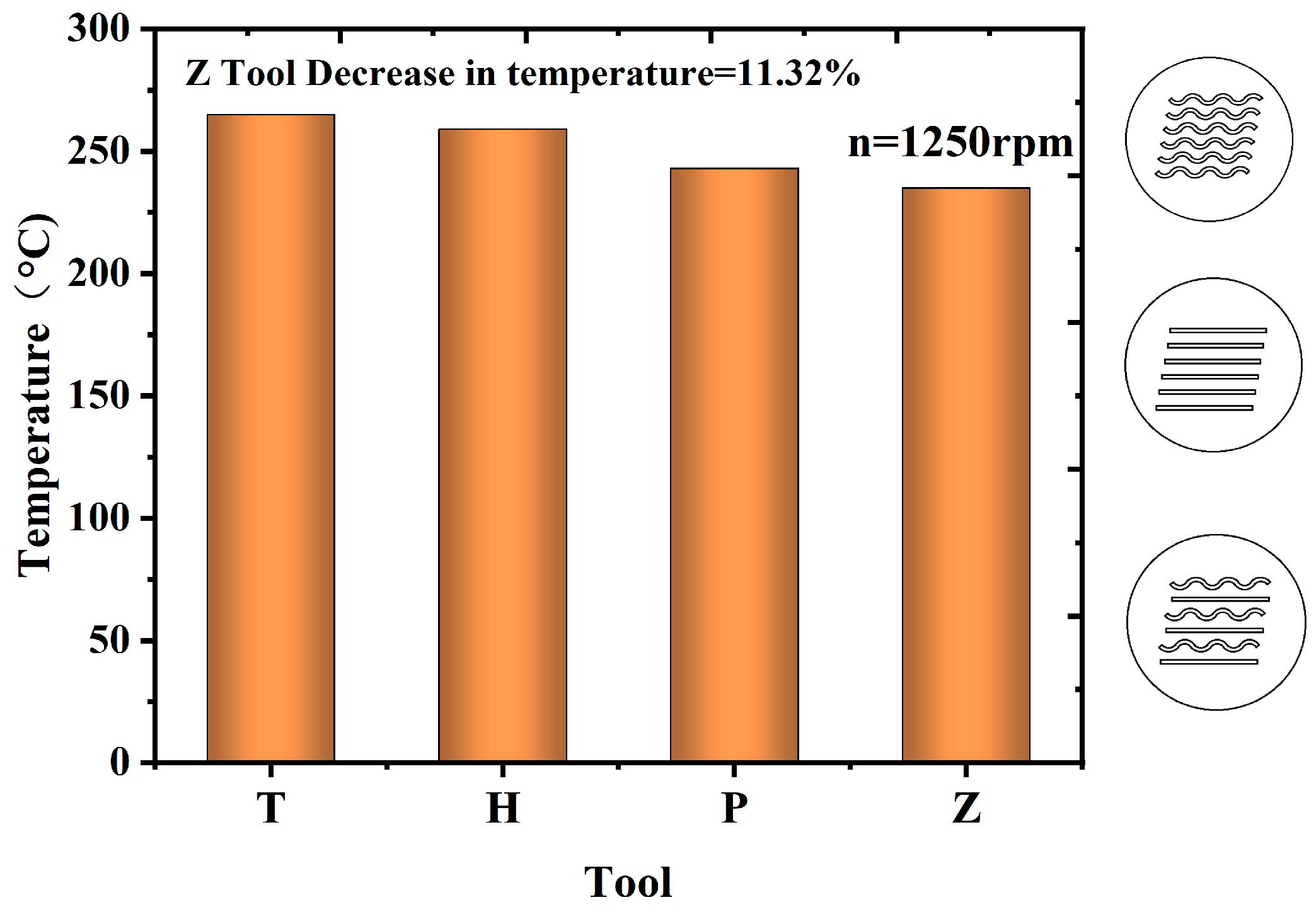
Figure 9.
Cutting temperature distribution of the tools. (a) No micro-textured tools, (b) micro-textured tools.
Figure 9.
Cutting temperature distribution of the tools. (a) No micro-textured tools, (b) micro-textured tools.

Figure 10.
Composite bionic micro-textured tool preparation.

Figure 11.
Shows the microstructure morphology with different microstructure spacing.

Figure 12.
Experimental equipment.

Figure 13.
Effect of combined bionic micro-texture parameters on cutting force at n = 1250 rpm.
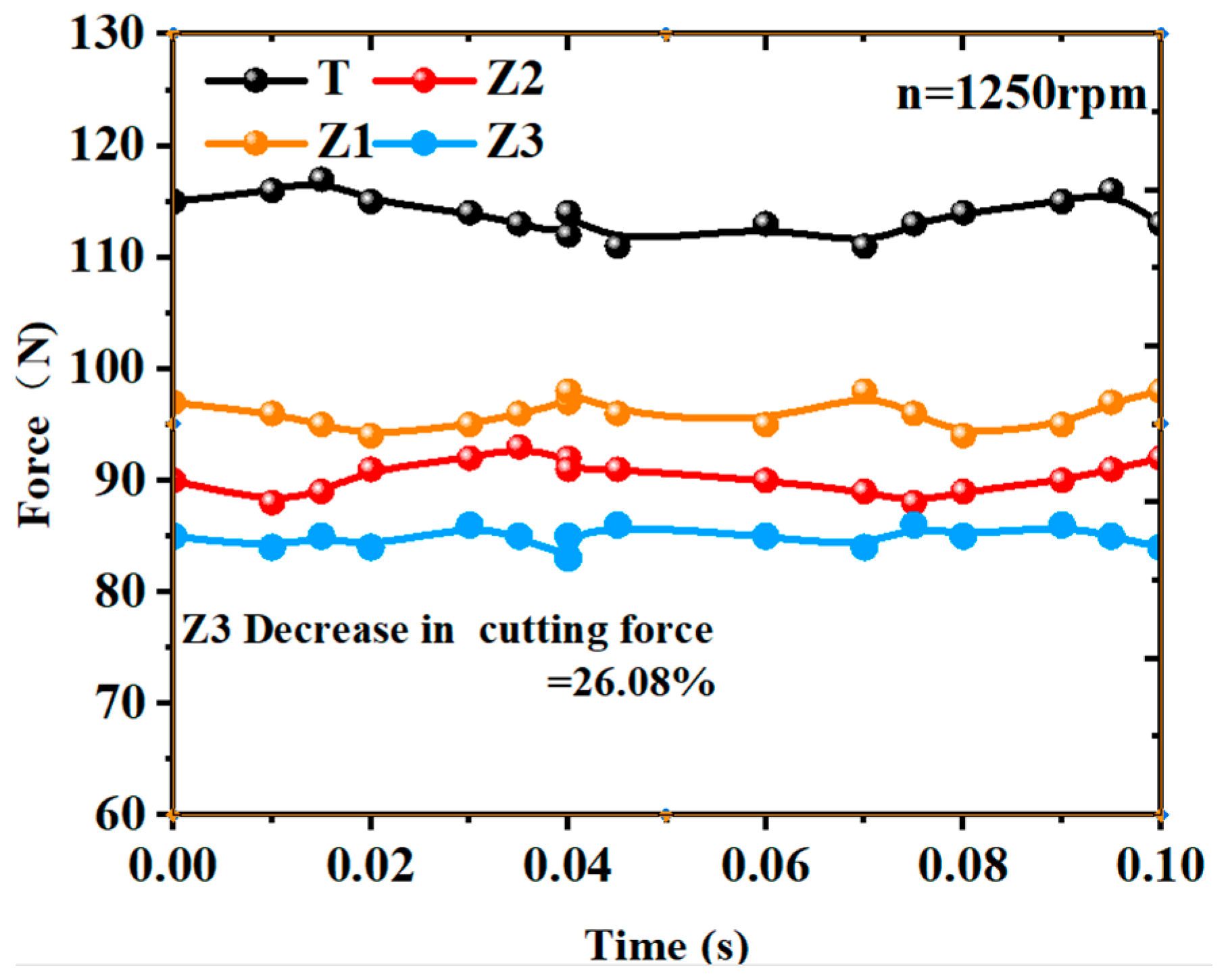
Figure 14.
Area of three bionic micro-textured structures (the step line is a line connecting the areas of the three micro-textured configurations).
Figure 14.
Area of three bionic micro-textured structures (the step line is a line connecting the areas of the three micro-textured configurations).
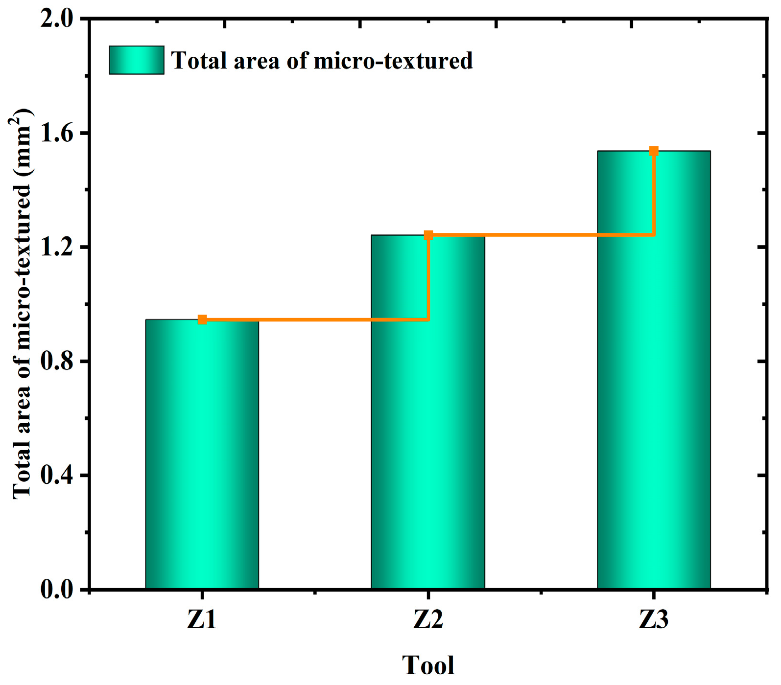
Figure 15.
Impact of combined bionic micro-textured elements on slicing forces across varying spindle velocities. (a) n = 800 rpm, (b) n = 1000 rpm.
Figure 15.
Impact of combined bionic micro-textured elements on slicing forces across varying spindle velocities. (a) n = 800 rpm, (b) n = 1000 rpm.
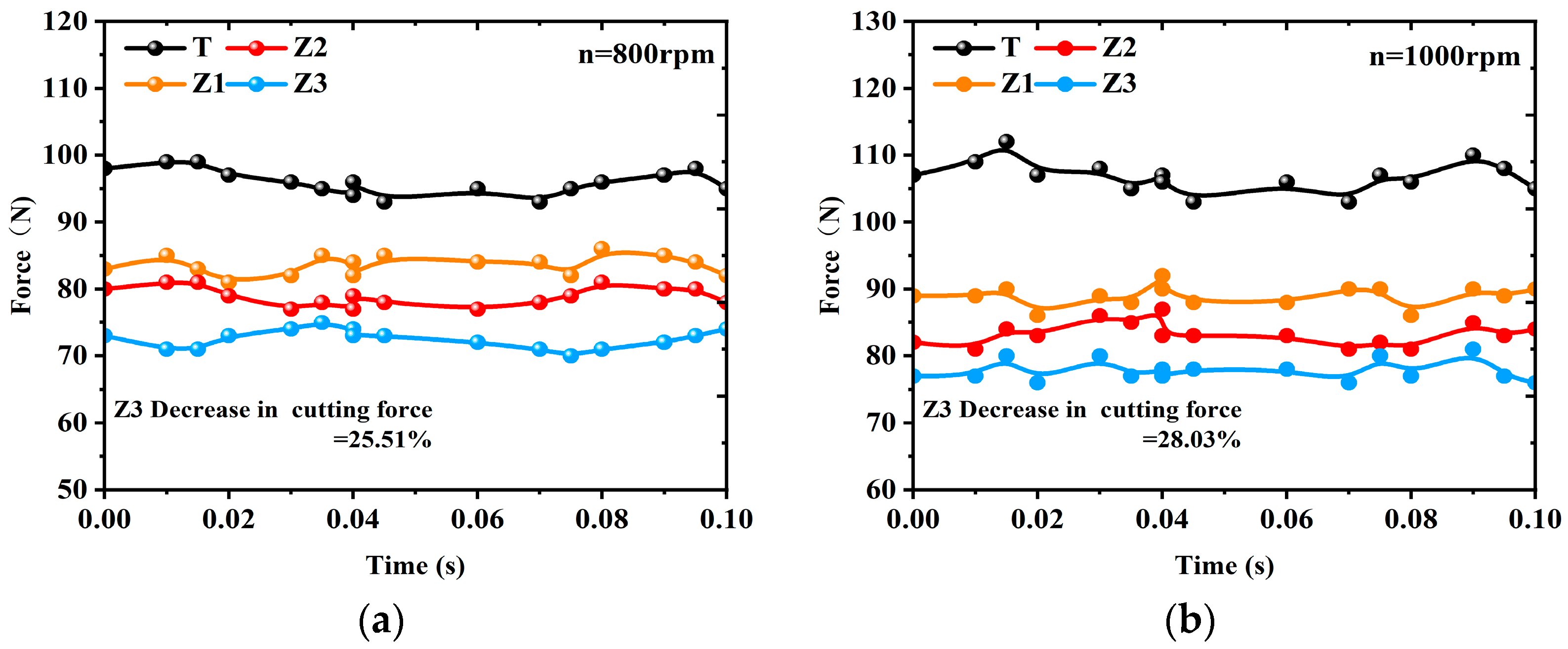
Figure 16.
Effect of combined bionic micro-textured parameters on surface roughness for n = 1250 rpm (the step line (SZ) is the average of the high and low points on the surface of the workpiece after machining).
Figure 16.
Effect of combined bionic micro-textured parameters on surface roughness for n = 1250 rpm (the step line (SZ) is the average of the high and low points on the surface of the workpiece after machining).
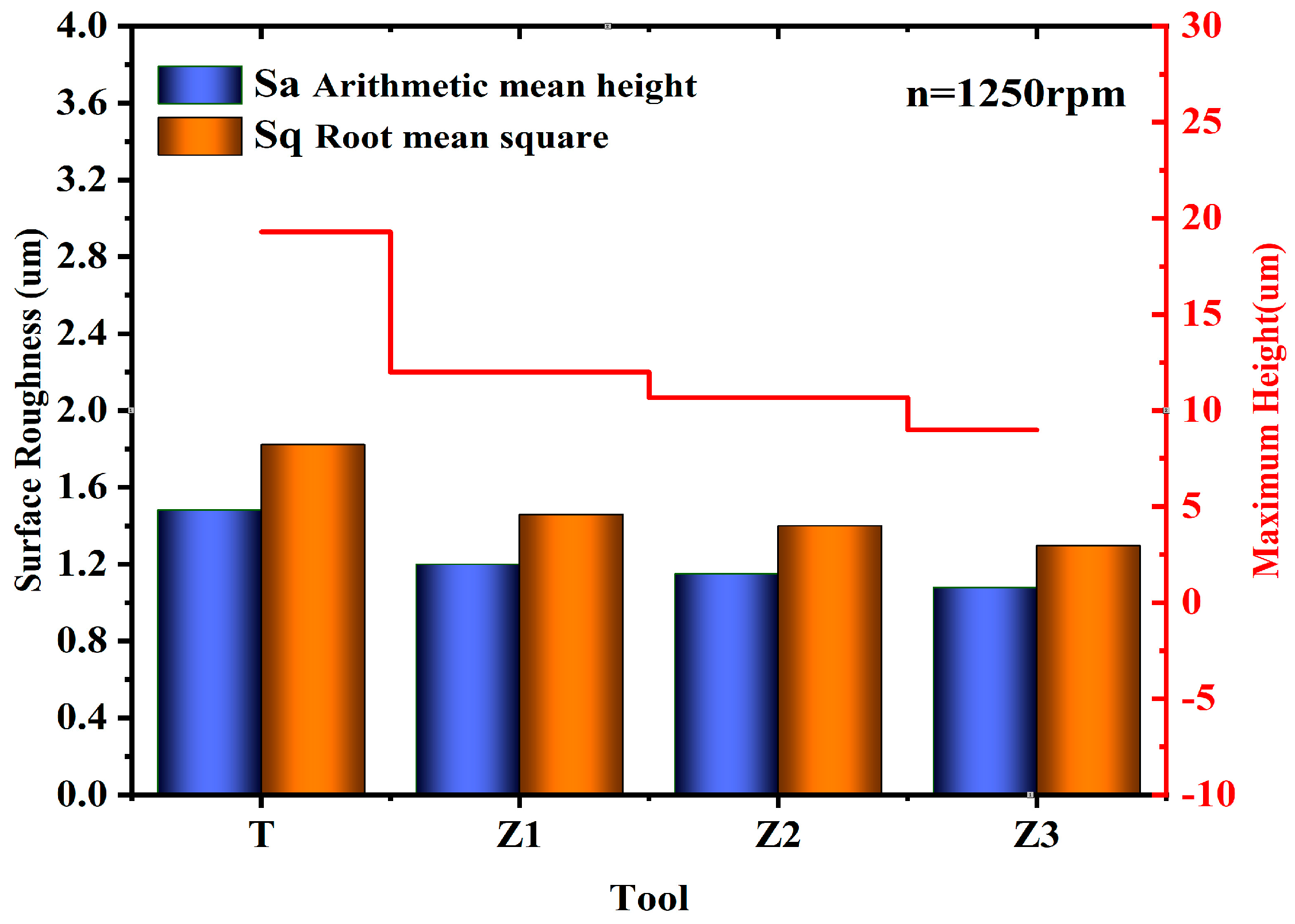
Figure 17.
The three-dimensional structure of the workpiece’s surface post-machining using a standard tool (T) and a variable-pitch micro-textured tool.
Figure 17.
The three-dimensional structure of the workpiece’s surface post-machining using a standard tool (T) and a variable-pitch micro-textured tool.

Figure 18.
The intertwining of chips following machining with four instruments at n = 1250 rpm.

Table 1.
Material property parameters of the bearing steel Johnson–Cook model.
| A (GPa) | B (GPa) | C | n | m | t0 (°C) | tm (°C) |
|---|---|---|---|---|---|---|
| 1.204 | 1.208 | 0.036 | 0.12 | 0.89 | 20 | 1180 |
Table 2.
Physical property parameters of bearing steel material.
| Material Properties | Young’s Modulus (Gpa) | Thermal Conductivity (W/m·K) | Poisson Ratio | Density (g/cm3) | Specific Heat (J/kg k) |
|---|---|---|---|---|---|
| Value | 210 | 43 | 0.3 | 7.85 | 458 |
Table 3.
Parameters of micro-texture size.
| Tool | Distance (µm) | Depth (µm) | Width (µm) | Length (µm) |
|---|---|---|---|---|
| Z1 | 150 | 70 | 50 | 1200 |
| Z2 | 200 | 70 | 50 | 1200 |
| Z3 | 300 | 70 | 50 | 1200 |
Table 4.
The chemical makeup of steel.
| C | Si | Mn | S | P | Cr | Mo |
|---|---|---|---|---|---|---|
| 0.95–1.05% | 0.15–0.35% | 0.20–0.40% | ≤0.020% | ≤0.027% | 1.40–1.65% | 0.08–0.15% |
Table 5.
Parameters for processing in finite element analysis.
| Group | Cutting Speed (rpm) | Feed f (mm/r) | Depth of Cut ap (mm) |
|---|---|---|---|
| 1 | 800 | 0.15 | 0.2 |
| 2 | 1000 | 0.15 | 0.2 |
| 3 | 1250 | 0.15 | 0.2 |
Disclaimer/Publisher’s Note: The statements, opinions and data contained in all publications are solely those of the individual author(s) and contributor(s) and not of MDPI and/or the editor(s). MDPI and/or the editor(s) disclaim responsibility for any injury to people or property resulting from any ideas, methods, instructions or products referred to in the content. |
© 2023 by the authors. Licensee MDPI, Basel, Switzerland. This article is an open access article distributed under the terms and conditions of the Creative Commons Attribution (CC BY) license (https://creativecommons.org/licenses/by/4.0/).
Share and Cite
MDPI and ACS Style
Xu, T.; Ma, C.; Shi, H.; Xiao, K.; Liu, J.; Li, Q. Effect of Composite Bionic Micro-Texture on Cutting Performance of Tools. Lubricants 2024, 12, 4. https://doi.org/10.3390/lubricants12010004
AMA Style
Xu T, Ma C, Shi H, Xiao K, Liu J, Li Q. Effect of Composite Bionic Micro-Texture on Cutting Performance of Tools. Lubricants. 2024; 12(1):4. https://doi.org/10.3390/lubricants12010004
Chicago/Turabian StyleXu, Tiantian, Chunlu Ma, Hu Shi, Kai Xiao, Jinpeng Liu, and Qinghua Li. 2024. "Effect of Composite Bionic Micro-Texture on Cutting Performance of Tools" Lubricants 12, no. 1: 4. https://doi.org/10.3390/lubricants12010004
Note that from the first issue of 2016, this journal uses article numbers instead of page numbers. See further details here.