
Open Source Laser Polymer Welding System: Design and Characterization of Linear Low-Density Polyethylene Multilayer Welds


Abstract
:
1. Introduction
2. Materials and Methods
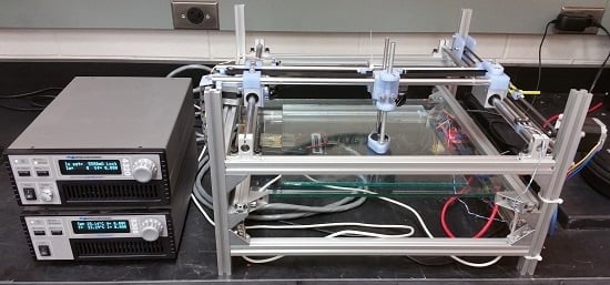
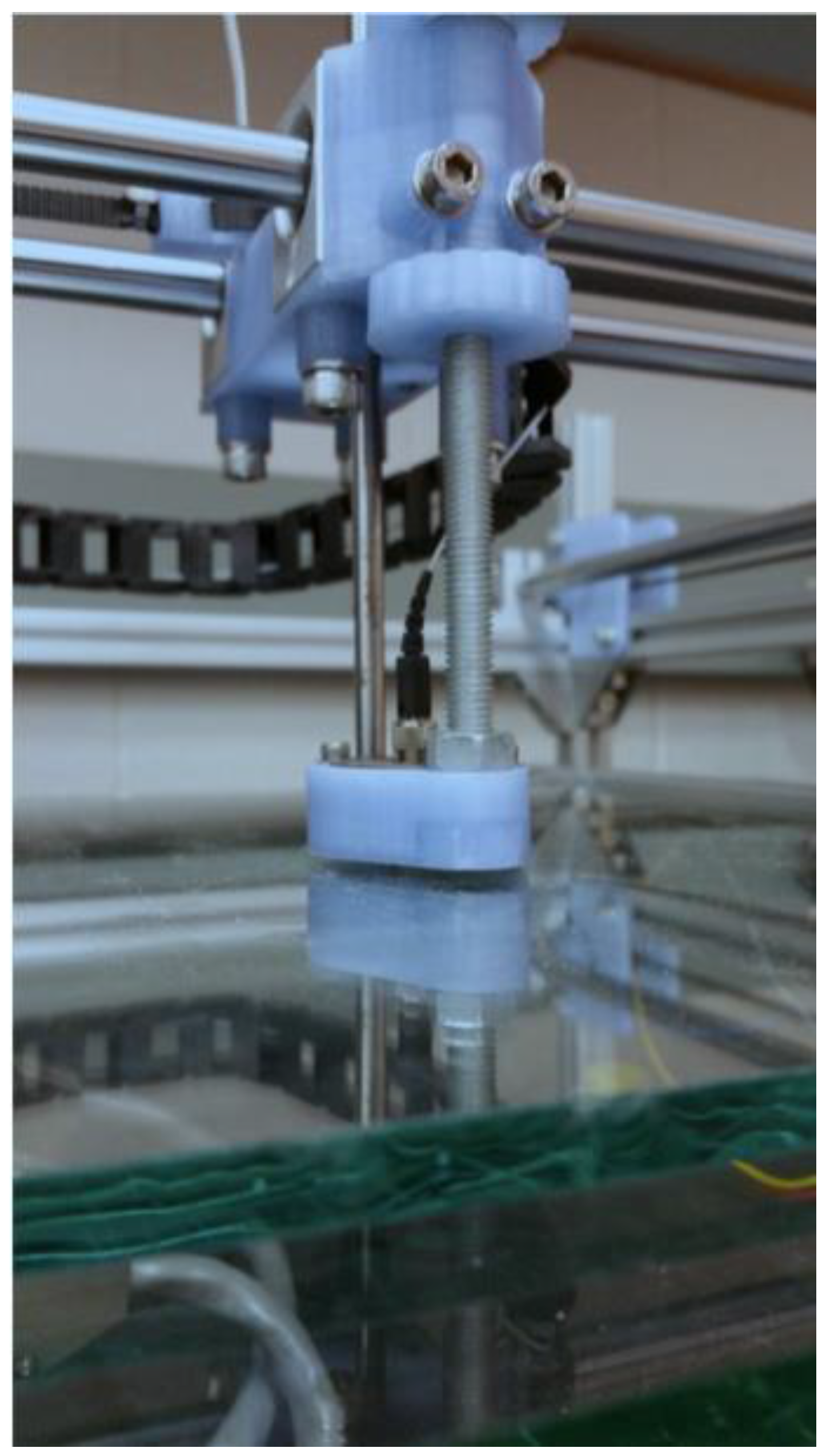
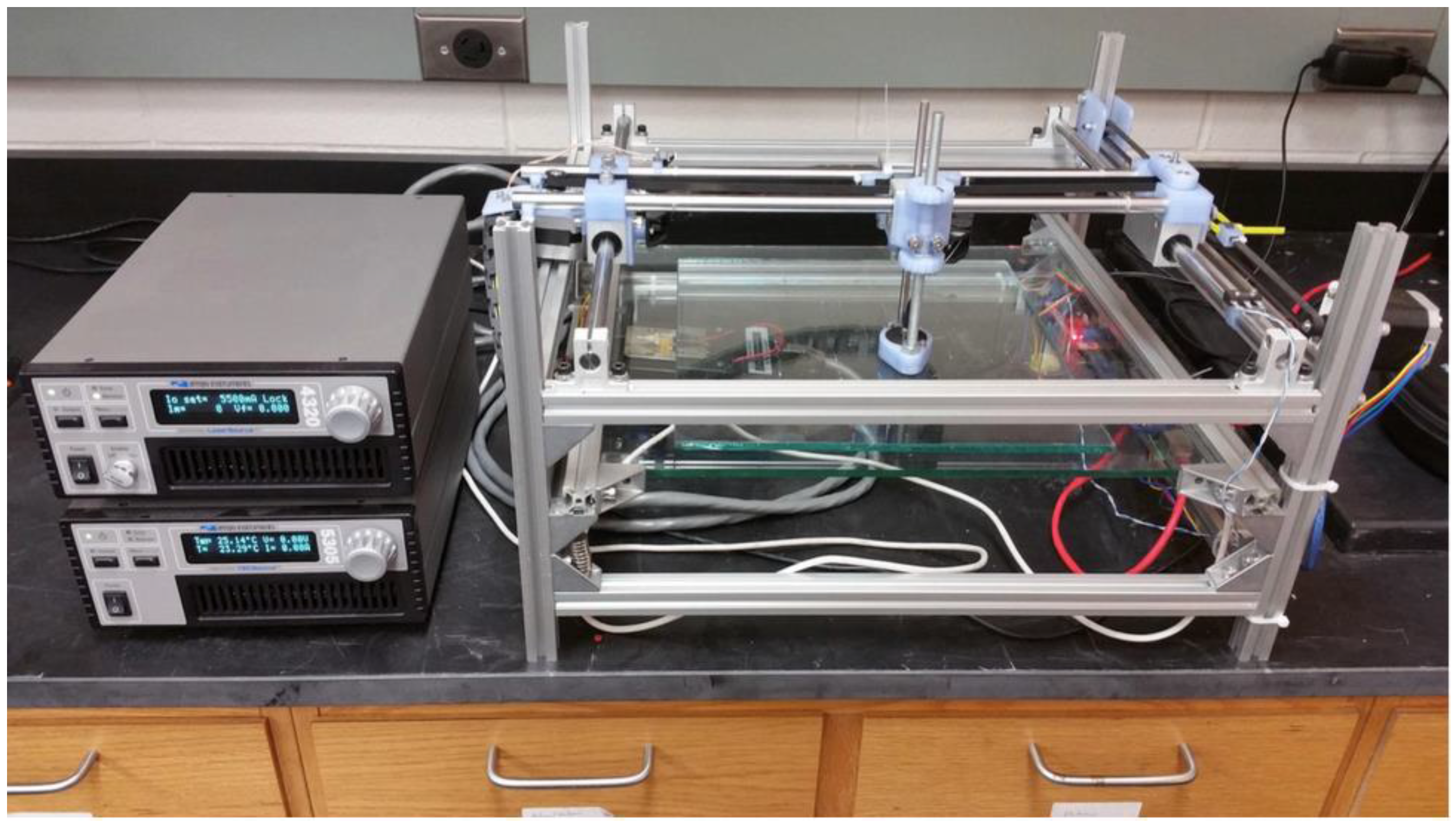
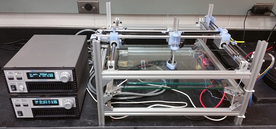
2.1. Laser Welder
2.2. Materials
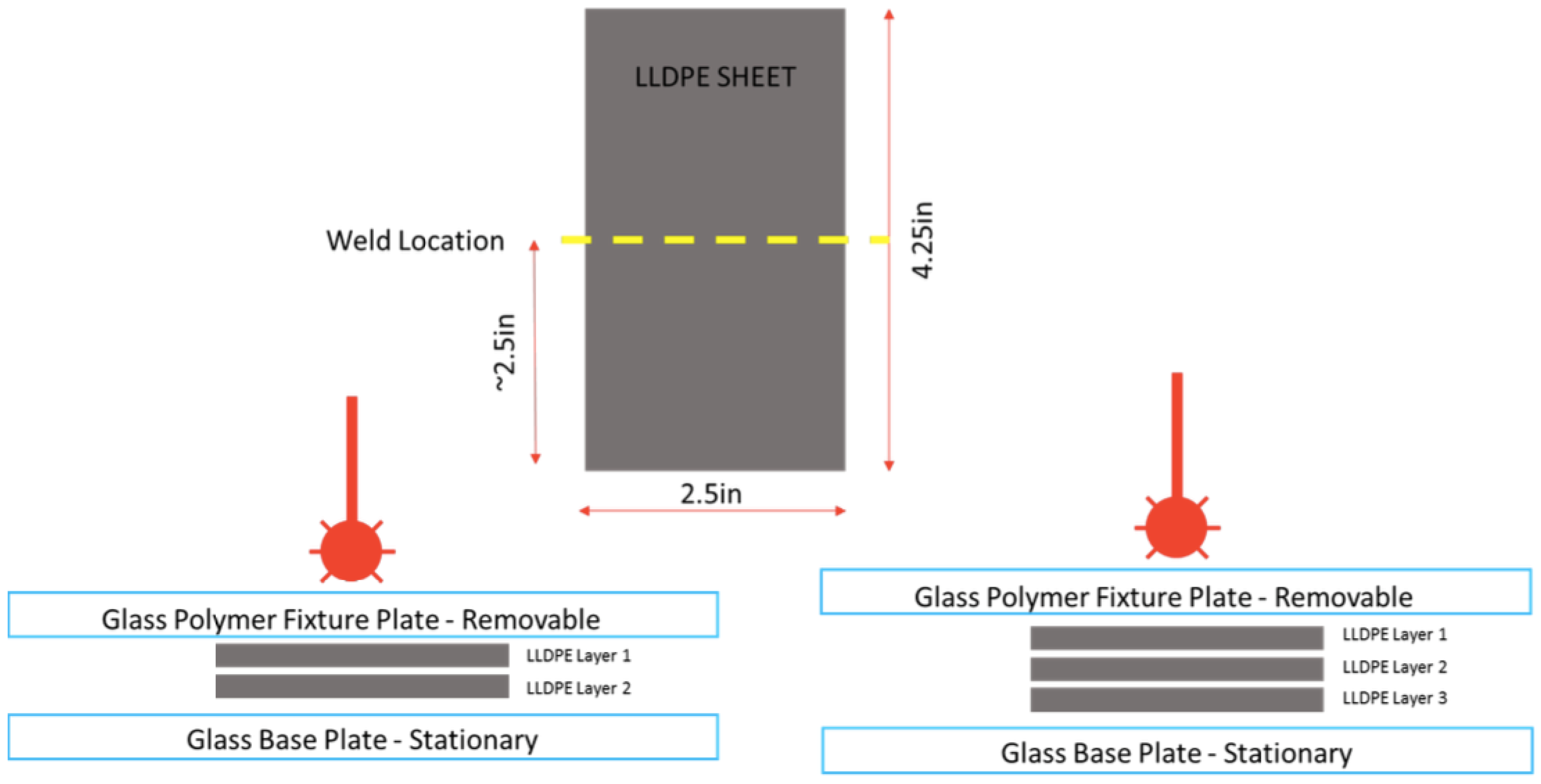
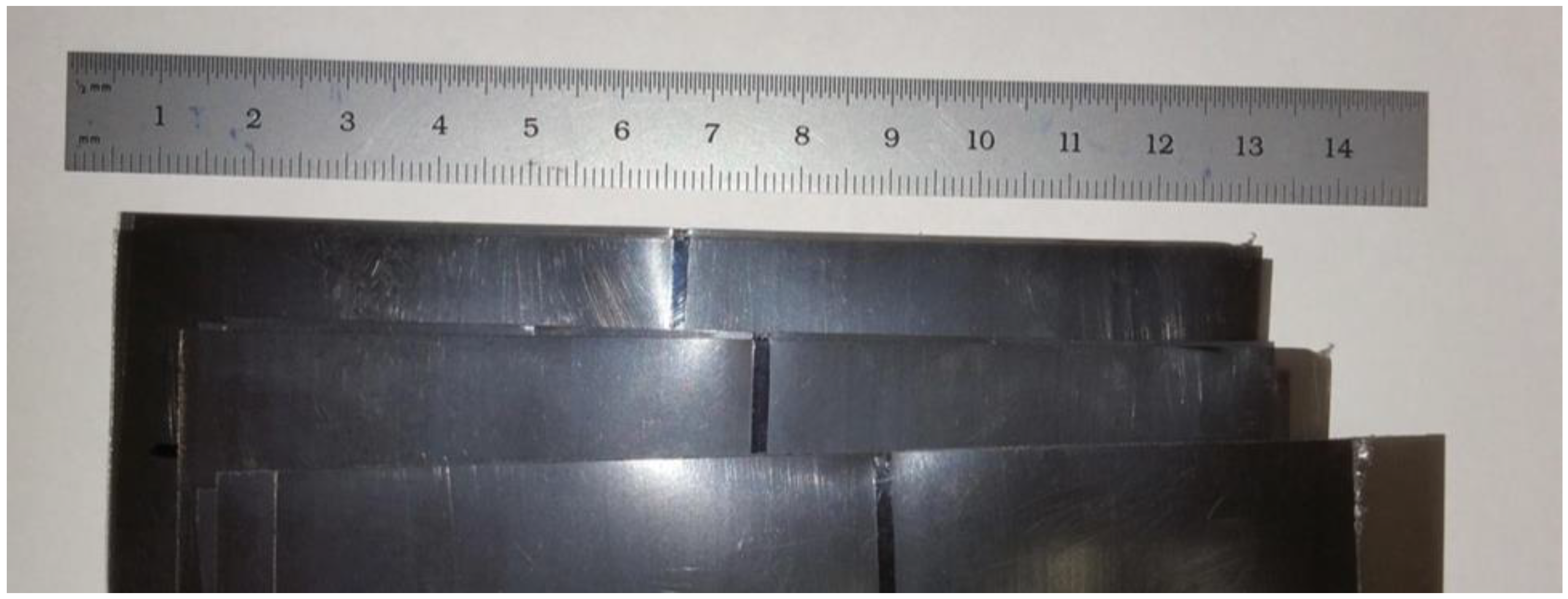
2.3. Fabrication
2.4. Characterization
2.4.1. Peak Load Determination
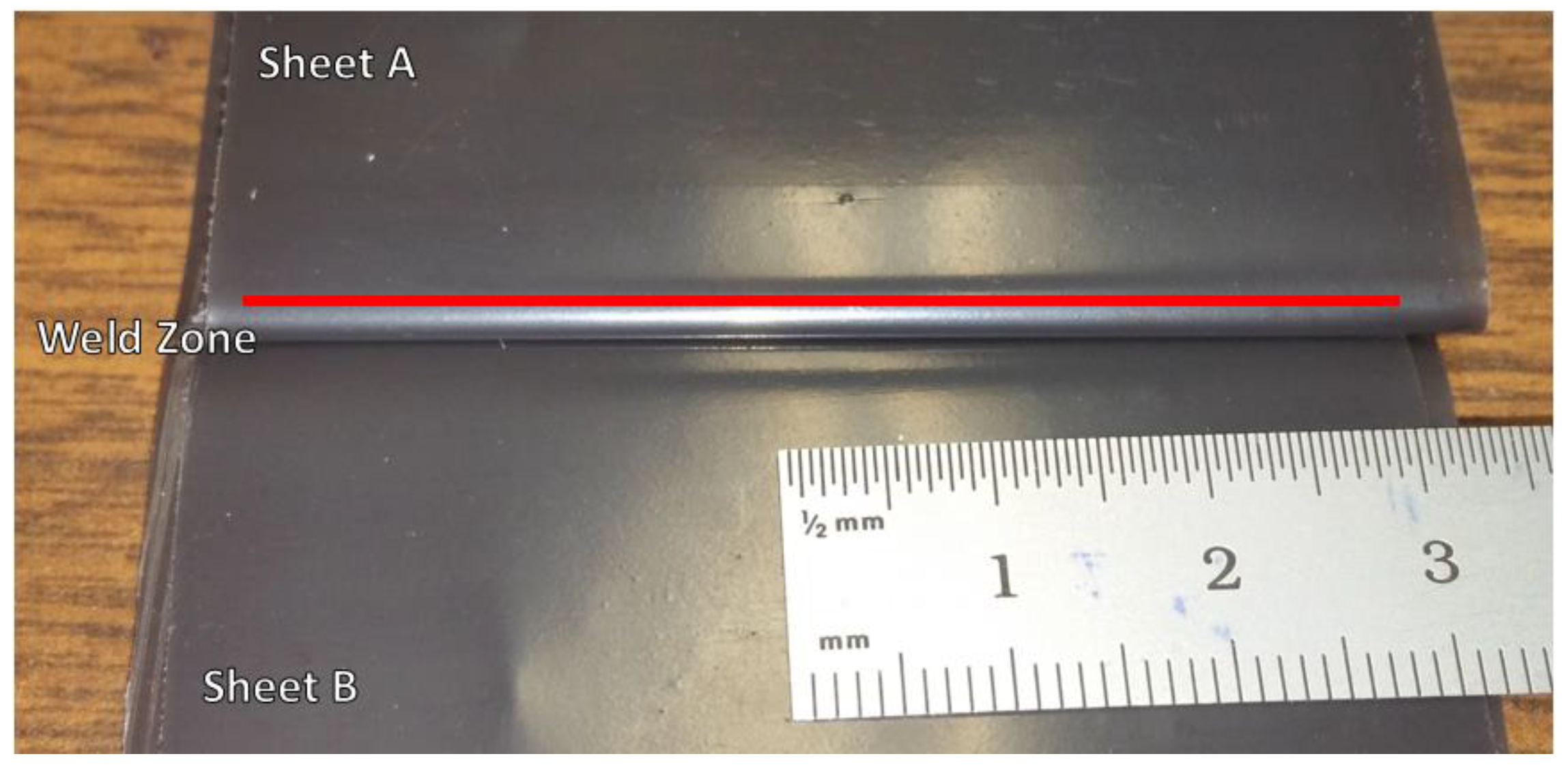
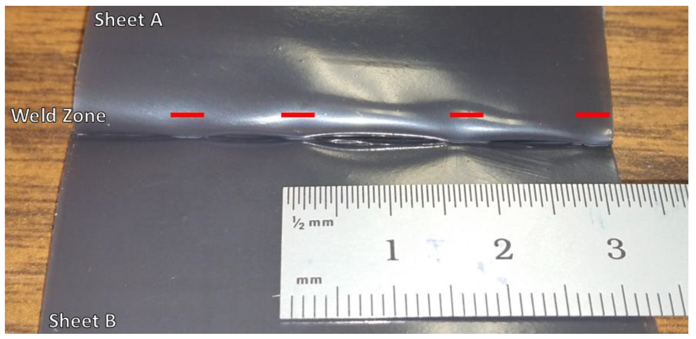
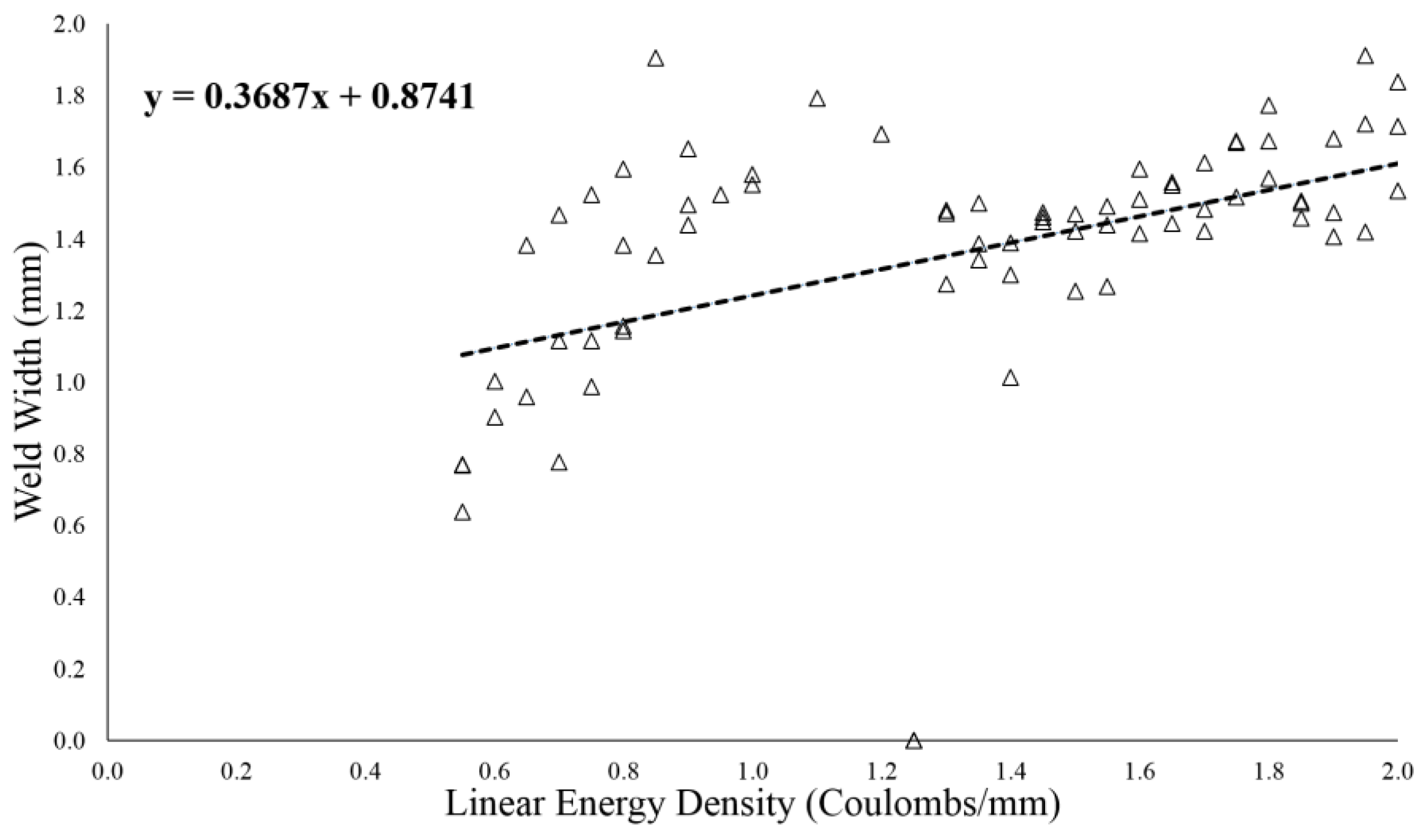
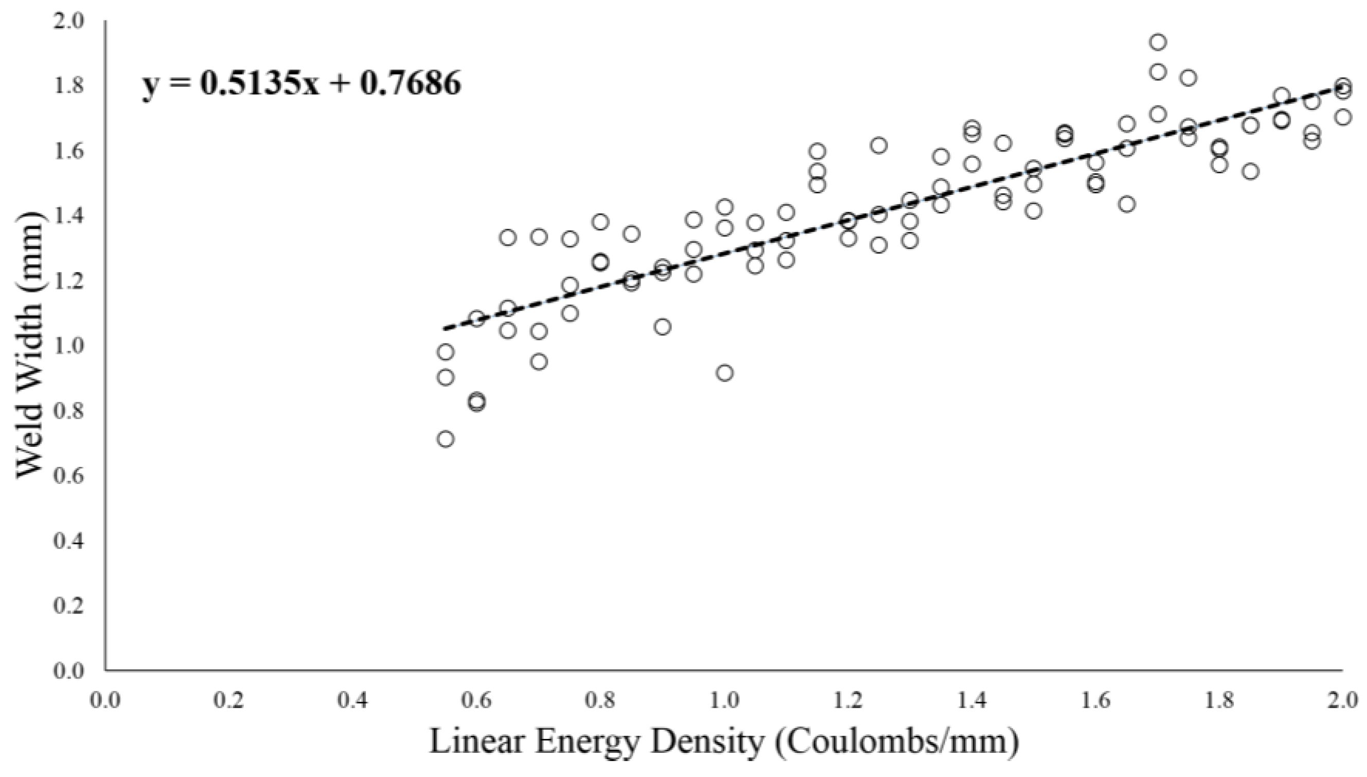
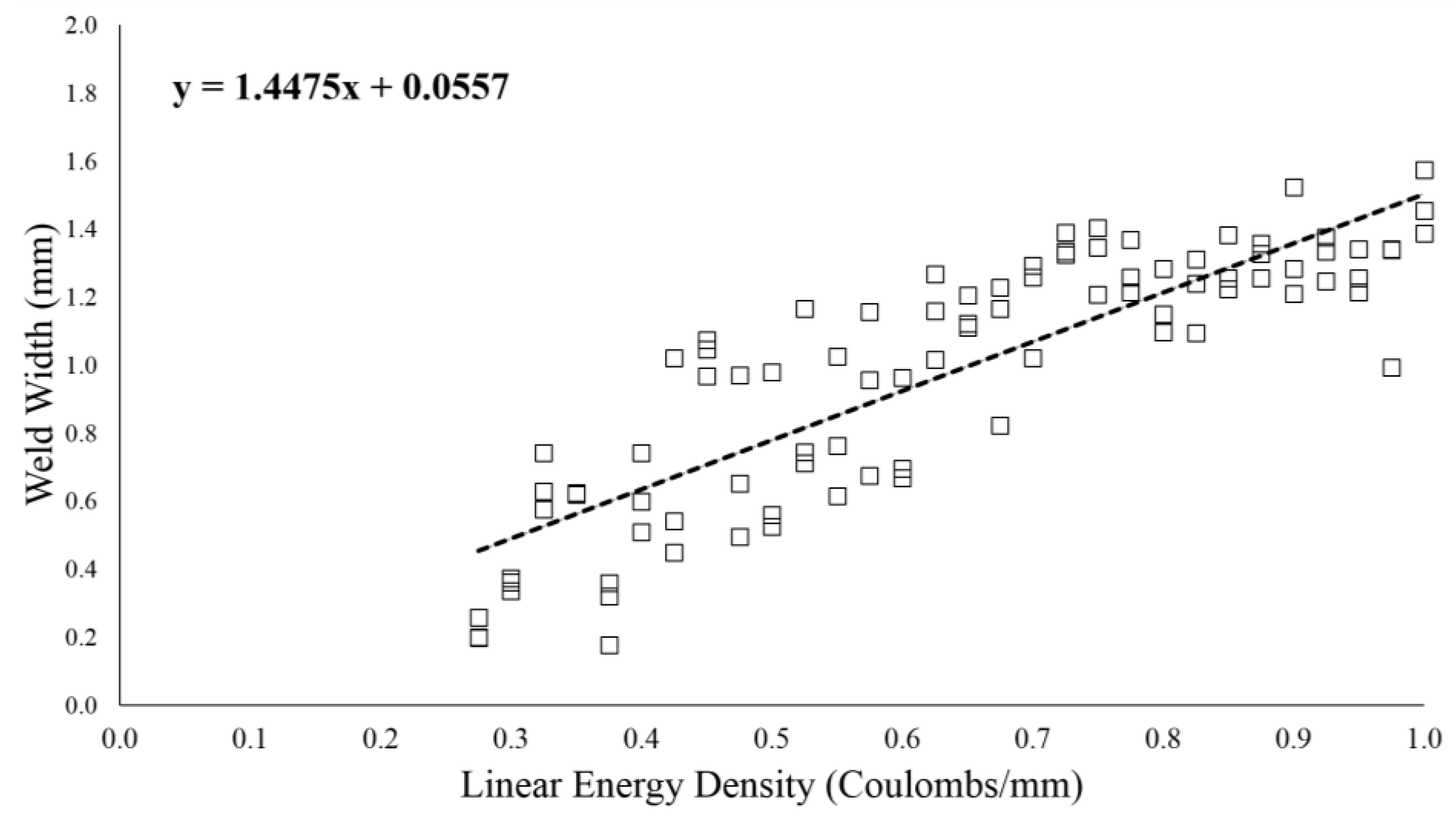
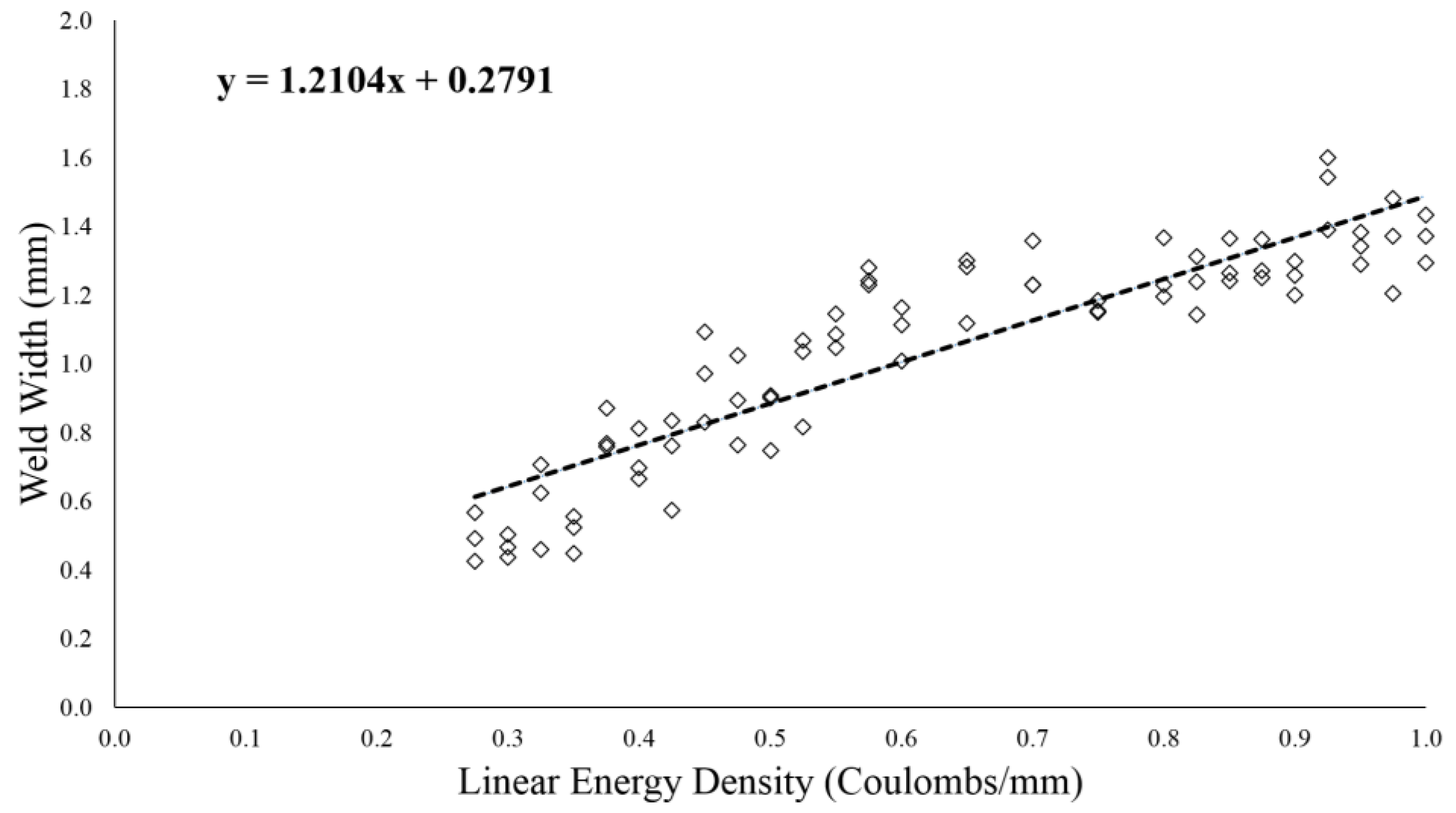
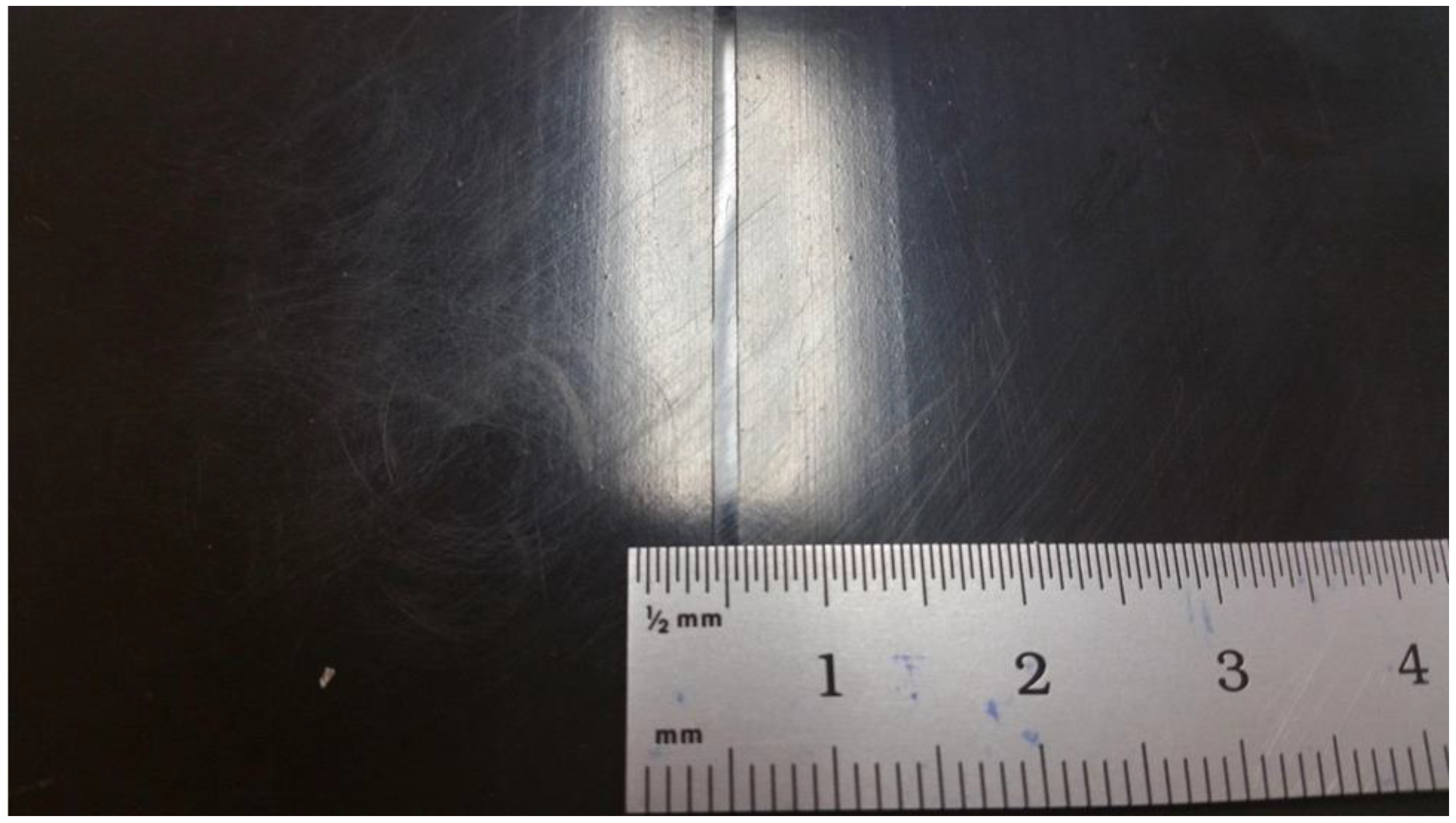
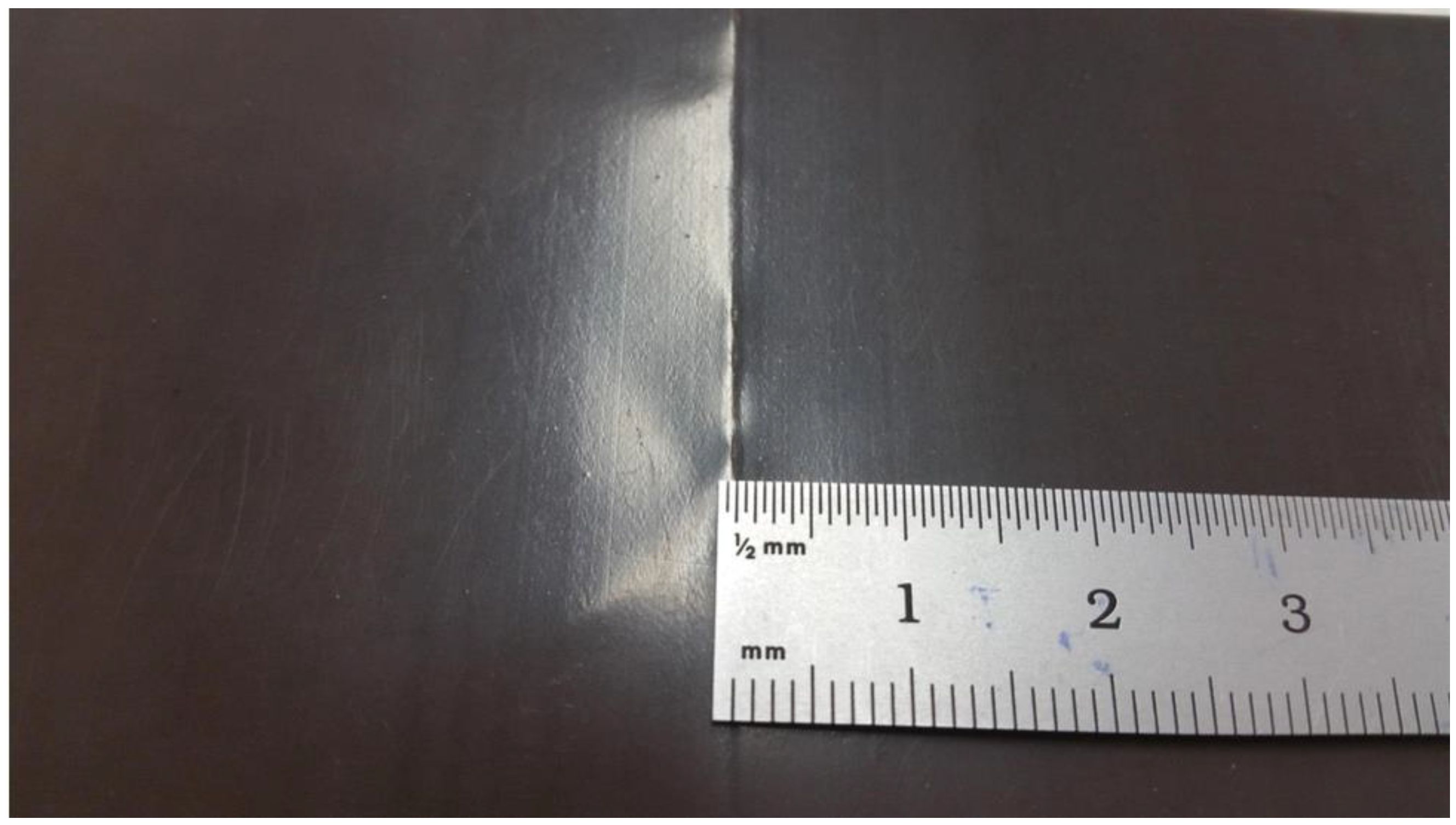
2.4.2. Weld Width (mm) and Resultant Energy Density (Coulombs/mm)
3. Results
3.1. Weld Width at Various Linear Energy Densities
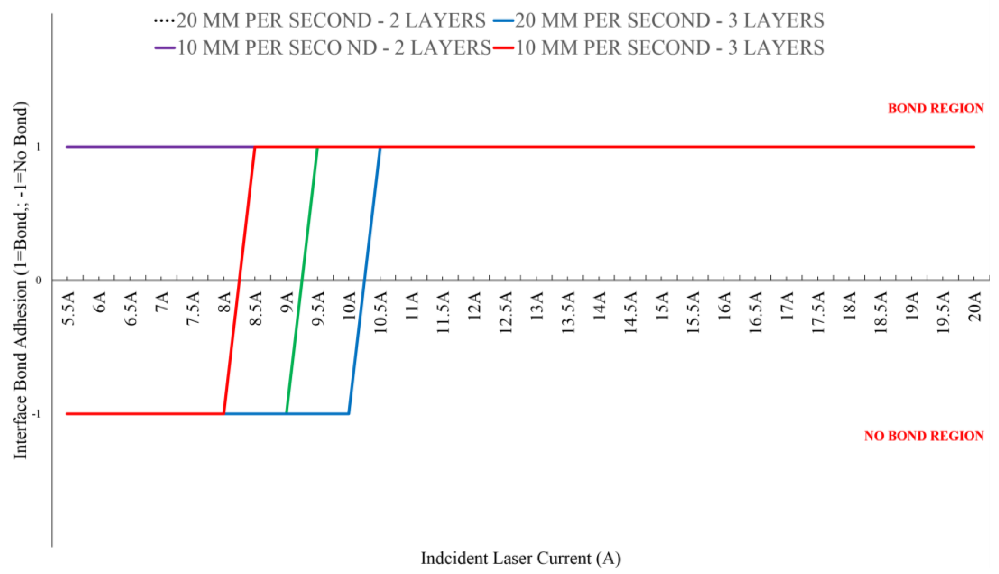
3.2. Polymer Weld Adhesion of Two and Three Layered LLDPE Systems Available
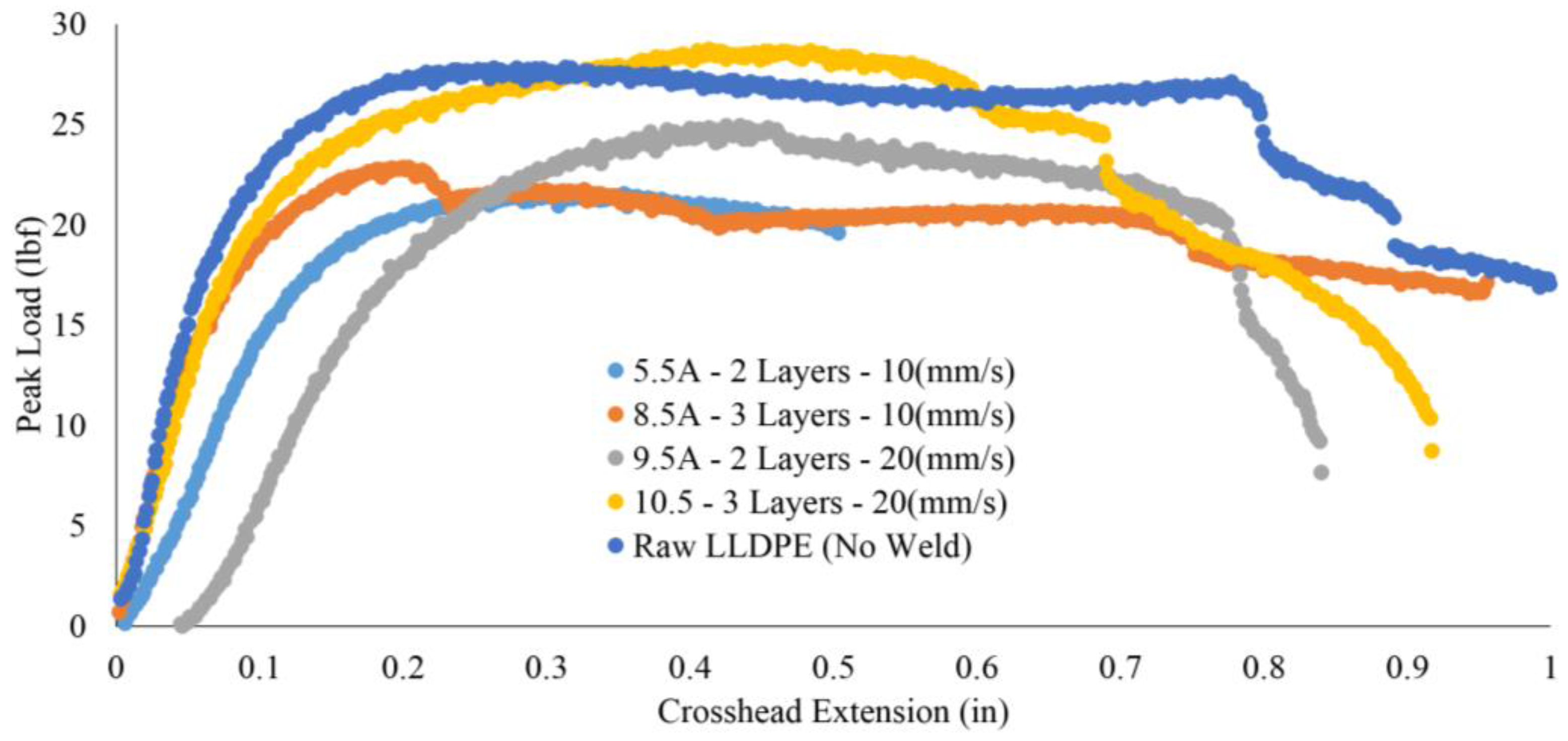
3.3. Mechanical Testing—Peak Load (lbf)
4. Discussion
5. Conclusions
Acknowledgments
Author Contributions
Conflicts of Interest
References
- Becker, F.; Potente, H. A step towards understanding the heating phase of laser transmission welding in polymers. Polym. Eng. Sci. 2002, 42, 365–374. [Google Scholar] [CrossRef]
- Garst, S.; Schuenemann, M.; Solomon, M.; Atkin, M.; Harvey, E. Fabrication of multilayered microfluidic 3D polymer packages. Proc. Electron. Compon. Technol. 2005, 1, 603–610. [Google Scholar]
- Brown, N.; Kerr, D.; Jackson, M.; Parkin, R. Laser welding of thin polymer films to container substrates for aseptic packaging. Opt. Laser Technol. 2000, 32, 139–146. [Google Scholar] [CrossRef]
- Bachmann, F. Industrial applications of high power diode lasers in materials processing. Appl. Surf. Sci. 2003, 208–209, 125–136. [Google Scholar] [CrossRef]
- Tsao, C.-W.; DeVoe, D.L. Bonding of thermoplastic polymer microfluidics. Microfluid. Nanofluid. 2009, 6, 1–16. [Google Scholar] [CrossRef]
- Arie, M.A.; Tiwari, R.; Shooshtari, A.H.; Dessiatoun, S.V.; Ohadi, M.M.; Pearce, J.M. Experimental Characterization of Heat Transfer in an Additively Manufactured Polymer Heat Exchanger. 2016. under review. [Google Scholar]
- Denkenberger, D.C.; Brandemuehl, M.J.; Pearce, J.M.; Zhai, J. Expanded microchannel heat exchanger: Design, fabrication, and preliminary experimental test. Proc. Inst. Mech. Eng. Part A J. Power Energy 2012, 226, 532–544. [Google Scholar] [CrossRef]
- Shao, J.; Yan, Y. Review of techniques for on-line monitoring and inspection of laser welding. J. Phys. Conf. Ser. 2005, 15, 101–107. [Google Scholar] [CrossRef]
- Norman, P.; Engström, H.; Kaplan, A.F.H. Theoretical analysis of photodiode monitoring of laser welding defects by imaging combined with modelling. J. Phys. D Appl. Phys. 2008, 41, 195502. [Google Scholar] [CrossRef]
- Ghorbel, E.; Hadriche, I.; Casalino, G.; Masmoudi, N. Characterization of thermo-mechanical and fracture behaviors of thermoplastic polymers. Materials 2014, 7, 375–398. [Google Scholar] [CrossRef]
- Ghorbel, E.; Casalino, G.; Abed, S. Laser diode transmission welding of polypropylene: Geometrical and microstructure characterisation of weld. Mater. Des. 2009, 30, 2745–2751. [Google Scholar] [CrossRef]
- Hadriche, I.; Ghorbel, E.; Masmoudi, N.; Casalino, G. Investigation on the effects of laser power and scanning speed on polypropylene diode transmission welds. Int. J. Adv. Manuf. Technol. 2010, 50, 217–226. [Google Scholar] [CrossRef]
- Torrisi, L.; Caridi, F.; Visco, A.M.; Campo, N. Polyethylene welding by pulsed visible laser irradiation. Appl. Surf. Sci. 2011, 257, 2567–2575. [Google Scholar] [CrossRef]
- Torrisi, L.; Visco, A.M.; Campo, N.; Caridi, F. Pulsed laser treatments of polyethylene films. Nucl. Instrum. Methods Phys. Res. Sect. B Beam Interact. Mater. Atoms 2010, 268, 3117–3121. [Google Scholar] [CrossRef]
- Dowding, C.; Dowding, R.; Franceschini, F.; Griffiths, J. The effect of laser power, traverse velocity and spot size on the peel resistance of a polypropylene/adhesive Bond: Non-contact laser based technique of polymer bonding. Packag. Technol. Sci. 2015, 28, 621–632. [Google Scholar] [CrossRef]
- Pearce, J.M. Open-Source Lab: How to Build Your Own Hardware and Reduce Research Costs; Elsevier: Waltham, MA, USA, 2014. [Google Scholar]
- OpenSCAD. Available online: http://www.openscad.org/ (accessed on 21 April 2016).
- Jones, R.; Haufe, P.; Sells, E. Reprap—The replicating rapid prototype. Robotica 2011, 29, 177–191. [Google Scholar] [CrossRef]
- Bowyer, A. 3D printing and humanity’s first imperfect replicator. 3D Print. Addit. Manuf. 2014, 1, 4–5. [Google Scholar] [CrossRef]
- Sells, E.; Bailard, S.; Smith, Z.; Bowyer, A.; Olliver, V. RepRap: The replicating rapid prototyper-maximizing customizability by breeding the means of production. In Handbook of Research in Mass Customization and Personalization, Volume 1: Strategies and Concepts; Pillar, F.T., Tseng, M.M., Eds.; World Scientific: Hackensack, NJ, USA, 2009; pp. 568–580. [Google Scholar]
- Rundle, G.A. Revolution in the Making: 3D Printing, Robots and the Future; Affirm Press: South Melbourne, Australia, 2014. [Google Scholar]
- Open Science Framework. Available online: https://osf.io/r7hn6/ (accessed on 11 April 2016).
- GNU Operating System. Available online: http://www.gnu.org/licenses/gpl-3.0.en.html (accessed on 22 May 2016).
- Laser Welding Protocol (MOST). Available online: http://www.appropedia.org/Laser_welding_protocol:_MOST (accessed on 4 April 2016).
- Irwin, J.; Pearce, J.M.; Opplinger, D.; Anzalone, G. The RepRap 3-D printer revolution in STEM education. In Proceedings of the 121st ASEE Annual Conference and Exposition, Indianapolis, IN, USA, 15–18 June 2014; Paper ID #8696.
- RepRap. Available online: http://reprap.org/wiki/Melzi (accessed on 4 April 2016).
- Raspberry Pi. Available online: https://www.raspberrypi.org/ (accessed on 4 April 2016).
- Wijnen, B.; Anzalone, G.C.; Haselhuhn, A.S.; Sanders, P.G.; Pearce, J.M. Free and open-source control software for 3-D motion and processing. J. Open Res. Softw. 2016, 4. [Google Scholar] [CrossRef]
- Github “Franklin”. Available online: https://github.com/mtu-most/franklin (accessed on 15 March 2016).
- AWWA C105-10 Polyethylene Encasement for Ductile Iron Pipe Systems. Available online: http://awwa.org/store/productdetail.aspx?productid=25362 (accessed on 17 May 2016).
- Infinity Plastics Datasheet. Available online: http://www.infinityplastics.net/downloads/PollyWrap.pdf (accessed on 17 May 2016).
- ASTM International. Standard Test Method for Tensile, Compressive, and Flexural Creep and Creep-Rupture of Plastic; ASTM Test Method D2990-01 (Superseded by ASTM Test Method D2009-09); ASTM: West Conshohocken, PA, USA, 2001. [Google Scholar]
- ASTM International. Standard Test Method for Tensile Properties of Plastics; ASTM Test Method D638-02a (Superseded by ASTM Test Method D838-14); ASTM: West Conshohocken, PA, USA, 2002. [Google Scholar]
- Rasband, W.S. ImageJ; U.S. National Institues of Health: Bethesda, MD, USA, 1997–2015; Available online: http://imagej.nih.gove/ij/ (accessed on 17 March 2016).
- McGrath, G.C.; Cawley, W.H. Devloping Cost Effective Laser Welding Parameters for Weldable Resins and Application to the Medical Segment. Available online: http://www.clearweld.com/edufiles/Developing%20Cost%20Effective%20Laser%20Welding%20Parameters%20For%20Weldable%20Resins%20And%20Application%20To%20The%20Medical%20Segment.pdf (accessed on 20 March 2016).
- Denkenberger, D.; Parisi, M.; Pearce, J.M. Towards low-cost microchannel heat exchangers: Vehicle heat recovery ventilator prototype. In Proceedings of the 10th International Conference on Heat Transfer, Fluid Mechanics and Thermodynamics (HEFAT), Orlando, FL, USA, 14–16 July 2014.
- Ohadi, M.M. Heat transfer enhancement in heat exchangers. ASHRAE J. 1991, 33, 6–50. [Google Scholar]
- Denkenberger, D.C.; Pearce, J.M. Compound parabolic concentrators for solar water heat pasteurization: Numerical simulation. In Proceedings of the 2006 International Conference of Solar Cooking and Food Processing, Granada, Spain, 12–16 July 2006; p. 108.
- Amanat, N.; James, N.L.; McKenzie, D.R. Welding methods for joining thermoplastic polymers for the hermetic enclosure of medical devices. Med. Eng. Phys. 2010, 32, 690–699. [Google Scholar] [CrossRef] [PubMed]
- Khan Malek, C.G. Laser processing for bio-microfluidics applications (part II). Anal. Bioanal. Chem. 2006, 385, 1362–1369. [Google Scholar] [CrossRef] [PubMed]
- Coelho, J.P.; Abreu, M.A.; Pires, M.C. High-speed laser welding of plastic films. Opt. Lasers Eng. 2000, 34, 385–395. [Google Scholar] [CrossRef]
- Trapani, K.; Redón Santafé, M. A review of floating photovoltaic installations: 2007–2013: A review of floating photovoltaic installations. Prog. Photovolt: Res. Appl. 2015, 23, 524–532. [Google Scholar] [CrossRef]
- Pringle, A.M.; Handler, R.R.; Pearce, J.M. Aquavoltaics: Synergies for Dual Use of Water Area for Solar Photovoltaic Electricity Generation and Aquaculture. 2016. under review. [Google Scholar]
- Trapani, K. Flexible Floating Thin Film Photovoltaic (PV) Array Concept for Marine and Lacustrine Environments. Doctoral Dissertation, Laurentian University of Sudbury, Sudbury, CA, USA, 16 May 2014. Available online: https://zone.biblio.laurentian.ca/dspace/handle/10219/2199 (accessed on 25 May 2016). [Google Scholar]
- Pearce, J.M.; Lau, A. Net energy analysis for sustainable energy production from silicon based solar cells. ASME 2002, 181–186. [Google Scholar] [CrossRef]
- Kim, H.C.; Fthenakis, V.; Choi, J.K.; Turney, D.E. Life cycle greenhouse gas emissions of thin-film photovoltaic electricity generation. J. Ind. Ecol. 2012, 16 (Suppl. 1), S110–S121. [Google Scholar] [CrossRef]


| Part Name/Description | Count | Rendered Image | Part Name/Description | Count | Rendered Image |
|---|---|---|---|---|---|
| Controller standoff for attaching controller to frame | 1 |  | Laser carriage for mounting laser to holder apparatus | 1 |  |
| Limit switch mount for mechanical switches to appropriate guide rods | 2 |  | M8 thumbscrew for adjusting z-position of laser carriage | 2 |  |
| X-carriage cable mount for attaching a cable carrier to the x-carriage | 1 |  | X-carriage for connecting x-axis linear bearings to x-axis drive belt, laser carriage, and cable carrier | 1 |  |
| X-clamp for securing x-axis guide rods to y-bearings and for holding x-axis idler | 2 |  | X fixed cable carrier mount for attaching cable carrier to y-bearing | 1 |  |
| X-idler cap for boxing x-axis idler bearing and shaft | 1 |  | X-motor mount for mounting x-motor to y-bearing | 1 |  |
| X-motor saddle cable carrier mount for mounting a cable carrier for the y-axis and for added rigidity of the x-motor mount | 1 |  | Y cable mount for mounting fixed end of y-axis cable carrier | 1 |  |
| Y-carriage for connecting y-bearing to y-drive belt | 1 |  | Y-idler for holding y-axis idler bearing | 2 |  |
| Y-motor mount for attaching y-motor to frame | 1 |  | Fixed belt terminator for attaching drive belt to x and y-carriages and tensioning of open ended belting | 2 |  |
| Free belt terminator for tensioning of open ended belting | 2 |  | - | - | - |
| Variable | Value | Units |
|---|---|---|
| Mode | Io (ACC) | - |
| Io Limit 1 | 5.5–20 | Amps (A) |
| Im Limit | 20,400 | Microamps (μm) |
| Vf Limit | 5.1 | Volts (V) |
| Vf Sense | Internal | - |
| Cable R | 0.0 | Ohms (Ω) |
| Tolerance Io | 100 | Milliamps (mA) |
| On Delay | 0.0 | Milliseconds (ms) |
| Sample Material | Condition/Speed (mm/s) | LLDPE Layers | Peak Load (±σ) (lbf) | Incident Current Setting (A) |
|---|---|---|---|---|
| LLDPE | RAW | - | 26.6 (2.1) | - |
| LLDEP | 10 | 2 | 19.6 (3.8) | 5.5 |
| LLDPE | 10 | 3 | 25.3 (3.4) | 8.5 |
| LLDPE | 20 | 2 | 25.7 (1.4) | 9.5 |
| LLDPE | 20 | 3 | 25.4 (2.8) | 10.5 |
© 2016 by the authors; licensee MDPI, Basel, Switzerland. This article is an open access article distributed under the terms and conditions of the Creative Commons Attribution (CC-BY) license (http://creativecommons.org/licenses/by/4.0/).
Share and Cite
Laureto, J.J.; Dessiatoun, S.V.; Ohadi, M.M.; Pearce, J.M. Open Source Laser Polymer Welding System: Design and Characterization of Linear Low-Density Polyethylene Multilayer Welds. Machines 2016, 4, 14. https://doi.org/10.3390/machines4030014
Laureto JJ, Dessiatoun SV, Ohadi MM, Pearce JM. Open Source Laser Polymer Welding System: Design and Characterization of Linear Low-Density Polyethylene Multilayer Welds. Machines. 2016; 4(3):14. https://doi.org/10.3390/machines4030014
Chicago/Turabian StyleLaureto, John J., Serguei V. Dessiatoun, Michael M. Ohadi, and Joshua M. Pearce. 2016. "Open Source Laser Polymer Welding System: Design and Characterization of Linear Low-Density Polyethylene Multilayer Welds" Machines 4, no. 3: 14. https://doi.org/10.3390/machines4030014
APA StyleLaureto, J. J., Dessiatoun, S. V., Ohadi, M. M., & Pearce, J. M. (2016). Open Source Laser Polymer Welding System: Design and Characterization of Linear Low-Density Polyethylene Multilayer Welds. Machines, 4(3), 14. https://doi.org/10.3390/machines4030014