1. Introduction
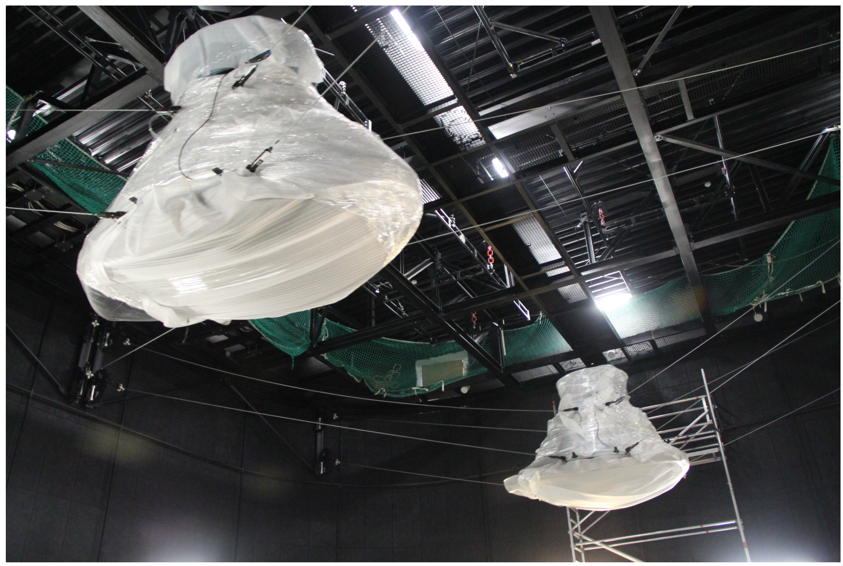
At the Universal Exposition EXPO 2015, being hosted in Milan, Italy, the German Pavilion has two giant cable-driven parallel robots as the main attractions. Picking up the theme of the EXPO “Feeding the Planet, Energy for Life”, the German Pavilion exhibits a show consisting of these robots, which represent two bees flying over Germany and illustrating everyday life in Germany. Each robot, illustrated in
Figure 1, consists of a platform looking like the eye of a bee and eight cables driven by winches. In addition to following a desired trajectory, the show is accompanied by live music and a video from a projector mounted inside the platform screening pictures on a perspex disc. Due to safety reasons and for a greater effect of the show, the cable robots are operated in suspended configuration, which restricts the movements significantly and constitutes a great technical challenge. Compared to industrial cable robots, high accuracy and rapid movements are second to the aesthetic and artistic aspects of the movement. A visually soft and smooth movement is desired, which is composed of both translational and rotational parts. Furthermore, the extensive exploitation of the generally six-dimensional workspace, especially the utilization of large rotations, is desired. This requires an interactive planning and programming system capable of giving feedback on the technical feasibility based on complex path verifications. These aspects are, in general, very different from an industrial path planner, which is not able to exploit these extreme poses and to compute optically smooth paths. A further important factor is the length of the desired path taking about 10 min per show. This leads to the requirement of a flexible path planning tool, which is able to split the whole path into several parts and smoothly combine them later into a complete show. The main challenge is designing a software tool complying with these complex conditions that can then be used by artists rather than trained engineers.
Figure 1.
Cable robots in the transporting film during the commissioning at the German Pavilion at EXPO 2015.
Figure 1.
Cable robots in the transporting film during the commissioning at the German Pavilion at EXPO 2015.
On behalf of the Federal Ministry of Economic Affairs and Energy, Messe Frankfurt has entrusted the German Pavilion EXPO 2015 Milan Consortium (ARGE) with the realization of the German Pavilion. The ARGE, as the general contractor, has taken on design planning and construction of the German Pavilion and the exhibition. Milla & Partner was responsible for the content concept, as well as the design of the exhibition and media. The Schmidhuber architectural office in Munich was responsible for the pavilion’s spatial concept, its architecture and general planning. Nüssli Deutschland from Roth was responsible for project management and construction. From the very beginning, the team from the University of Stuttgart has been involved in the design, motion planning and control of the cable-driven robots, which are the main attraction in the show.
As early as 1984, Landsberger presented some of the first ideas on cable-controlled parallel-linked robotic devices in a master thesis [
1]. Later, in 1989, the RoboCrane system at NIST was presented, which seems to be the first prototype, which was evaluated for large-scale handling [
2,
3]. Since 2006, a family of robots named IPAnemawas developed for medium- to large-scale inspection, handling and assembly operations [
4,
5]. The robot family Marionet includes a small-sized prototype for high-speed applications, a portable crane for rescue and components for personal assistance [
6]. In Canada, Otis recently developed a locomotion system [
7,
8]. Meanwhile, researchers are planning to build the world’s largest cable robot for positioning the reflector of the FASTtelescope [
9]. Besides these, a couple of other prototypes have been developed that cannot be listed here for the sake of brevity.
However, besides the well-known cable camera system at sporting events, only a few systems were deployed to be used outside research laboratories. Furthermore, to the best of the authors’ knowledge, no system was put into operation with safety requirements on the load to be transported by the robot. In this work, we address some issues related to the design and motion control of such robots for entertainment purposes.
This contribution is structured as follows:
Section 2 introduces the path planning issues for creating smooth motion.
Section 3 outlines the design and workflow of the programming system and its interaction with the controller. In
Section 4, different criteria are introduced that need to be verified before the motion can be executed on the cable robot. Finally, some results from the simulation are presented in
Section 5.
2. Path Planning
The requirements in regard to the path planning tool are very complex. These include maximal possible exploitation of the workspace, interactive feedback of technical feasibility, high usability and flexibility. In order to deal with these requirements, a path planning tool is developed in Python and provided as an add-on for Blender, which is an open-source 3D computer graphics software usually used for creating animated films, visual effects and interactive 3D applications; see [
10].
2.1. Mathematical Description of a Path
Each of the developed cable robots has six degrees of freedom (DOF) consisting of three DOF each in position and orientation. To force a cable robot to perform a desired motion, each of the six coordinates has to be defined over time. The position of the center of gravity of the cable robot’s mobile platform is referred to as
r containing the Cartesian coordinates
x,
y and
z, whereas the orientation
s is described by Cardan angles α, β and γ, also known as Tait–Bryan angles [
11]. Defining
r and
s for each time step
t leads to the main idea of path planning, which is schematically illustrated in
Figure 2, where the cable robot’s mobile platform is depicted as a cuboid.
Figure 2.
Main concept of path planning (left) and cubic Bézier curves (right).
Figure 2.
Main concept of path planning (left) and cubic Bézier curves (right).
A path is not defined for all time steps, but just by
n control points (illustrated by the symbol □ in
Figure 2), at which the position and orientation of the mobile platform can be changed by the designer. Therefore, a Bézier curve is used in order to facilitate the path planning as intuitively as possible for the designer. A Bézier curve is a smooth parametric curve, which is easily modifiable by moving its control points; see [
12]. In order to guarantee smooth trajectories in velocity and acceleration, a cubic Bézier curve is chosen. Such a curve consists of
segments
, each defined by two control points
,
and two handle points
,
, whose relation is depicted in
Figure 2. By introducing the time normalization
, a current point
can be described by:
with the starting time
at segment
i. The orientation is described by a Bézier curve, as well, substituting
in Equation (
1) by
, a three-times continuously differentiable curve, both in position and orientation, is guaranteed. By rotating the mobile platform based on Cardan angles, the orientation can be manipulated. The velocity of the mobile platform can only be influenced indirectly by setting the times of the respective control points. In order to get a desired motion, there are further extensions and features available, like mirroring, compressing or expanding, which simplify the design process. These features and others like loading and saving sequences are displayed in
Figure 3.
All features have in common that after manipulating a path, all relevant path verifications are executed automatically. The test results, described in detail in
Section 4, are visualized by coloring the respective parts of the path, which gives direct feedback on the technical feasibility to the user.
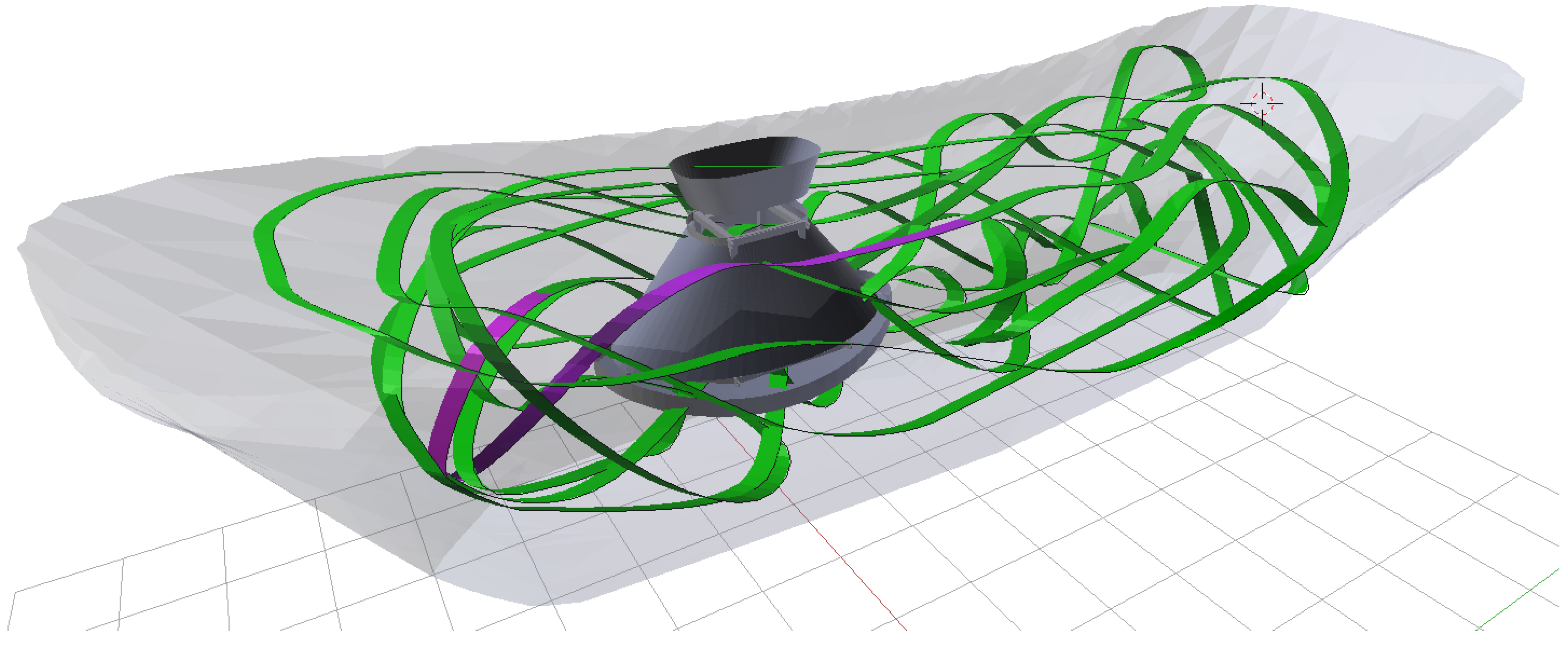
Figure 4 displays a trajectory of a cable robot, including the path verification results.
Figure 3.
Extract of the path planning tool provided as an add-on for Blender.
Figure 3.
Extract of the path planning tool provided as an add-on for Blender.
Figure 4.
Planned trajectory for a cable robot with visualization of the path verification results and workspace (green, path segment feasible; violet, not feasible).
Figure 4.
Planned trajectory for a cable robot with visualization of the path verification results and workspace (green, path segment feasible; violet, not feasible).
2.2. Connection of Paths
The trajectory, which is actually performed in the German Pavilion at the EXPO 2015 in Milan, takes about 500 s and contains several motions of different characters. In order to provide a better visualization of the trajectory in the design process and to avoid long computation times, such trajectories cannot be programmed as one path at once. Therefore, a concept is introduced to split the whole trajectory into sequences and connecting these sequences later on. In the following, the whole trajectory is referred to as the show, whereas the various parts of the show are referred to as sequences. It should be noted that a sequence consists of a path containing the pose information
r,
s,
t for the mobile platform at the control points, whereas a show consists only of links to the used sequences in the correct order. Consequently, planning a show means designing several sequences and connecting them in the desired order, which is the objective of this chapter. A sequence
i is given by the set of control points and handle points for the positions
and the rotations
and the corresponding time point
:
with the number of control points
and the tuple of the
j-th control point
with the corresponding left
and right handle point
. In the proposed tool, there exist two ways of describing a sequence. The first one is an absolute description of position and orientation characterized by a fixed relation to the environment. Secondly, a sequence can be described relatively with the consequence that there is no fixed relation and the sequence can be moved freely. This also enables the design of so-called loop sequences, which are defined as sequences with the same start and end conditions and can be attached to all existing sequences without determining in advance how often this loop is utilized. The clear distinction from usual sequences is made due to the fact that in the case of tracking a show, loop sequences are repeated until an external switch is triggered.
Connecting two absolutely described sequences
i and
is only possible if the following conditions hold:
The resulting control points and of the linked sequence are composed by the control points of sequence i and by the second up to the -th control points of sequence .
Roughly speaking, a relative sequence
is connected to any sequence
i by attaching the start of the second sequence to the end of the first one. The first
position coordinates of the resulting linked sequence
r are taken from the first sequence, whereby the following
control points are computed by:
Note that Equation (
6) also holds for
and
. In order to avoid unrealizable orientations, the control points of the orientations of sequence
i and
are combined and are retained unchanged.
2.3. Show Export
The motion of a cable robot is realized by controlling the eight winches independently from each other. Consequently, for each winch and each time point, information about cable length and cable velocity must be available in order to realize a control law. As until now the position and orientation is only known in Cartesian coordinates for each control point, there must be a conversion of the poses into joint-space coordinates, i.e., cable length and cable velocity and an interpolation of the coordinates between the control points to get equidistant data in time for the drivers. This is the main objective of the show export.
A trajectory of a show consists of
n control points with arbitrary time points
and has a time duration
T. Then, the coordinates of the position and orientation for each time point can be interpolated by the Bézier curve Equation (
1). The result is a trajectory for the position
and the orientation
containing information of
time points, where
is the user-selected sampling time. A show also involves special sequences and features in order to retain flexibility and to interact with the audience. These include the loop sequences and the insertion of pause points, which both require special consideration. A so-called pause point at time
is characterized by:
and is denoted by a special identifier in the export file in order to guarantee the interruption of the show at that time until an external signal is triggered. In order to satisfy Equation (
7), two third-order polynomials
and
are introduced, which substitute the trajectory
over the transition time
:
The conditions for a loop sequence starting at time point
with time duration
are given by:
and are satisfied by substituting the trajectory
over the transition time
by the two polynomials:
Note that for both Equation (
7) and Equations (
10) and (
11), the corresponding orientation conditions must also hold. The next step is to convert the Cartesian coordinates of the position
r and orientation
s into joint-space coordinates like cable length and cable velocity. Defining
,
yields the rotation matrix:
After computing the rotation matrix
R for all time points, all relevant path verifications can be executed, which are derived in
Section 4. Finally, the joint-space coordinates are computed by investigating kinematic dependencies and solving the resulting vector loop, which is elaborated in
Section 4.2. It should be noted, that all required information for controlling the mobile platforms is now available.
3. Robot Design and Workspace Estimation
Designing a cable robot suitable for a given task can be quite a challenging assignment due to the high number of parameters. If, furthermore, the number of cables is not fixed a
priori, the problem becomes even more complex [
13]. When developing a robot design, it is thus desirable to maximize the workspace, both translational and rotational, subject to some given conditions, e.g., minimum and maximum cable load, weight of the platform, the dimensions of the surrounding environment or the mobile platform itself. Needless to say, this requires a description of the workspace that provides quantitative and comparable values among a set of configurations. As elaborated in [
13], this could be sought in various ways, e.g., (i) using some force-distribution algorithm, (ii) exploring the workspace boundaries using universal methods, (iii) discretizing the workspace into a grid or, (iv) examining contours for fixed pose coordinates. However, all of these approaches involve different methodologies, and some even make assumptions about the robot that may not be applicable to every robot design.
A comparison of different robot configurations along a grid of poses is shown in [
13], also highlighting the difficulties of such comparison. The major fact in comparing configurations is the chosen workspace definition, which can change the size and shape of the workspace for one single configuration. There exists a trade-off between the size of the translational and the size of the rotational workspace. Till this date, this has not been confirmed quantitatively due to the non-intuitive nature of comparing two rotations,
i.e., coordinates of a subspace of
[
14].
Finding a robot configuration suitable for performing a certain task is an open research field due to the manifoldness of possible combinations [
15,
16,
17,
18], and a number of design choices have to be made to yield an implementable design. First and foremost, the number of cables has to be set being most influential on the capabilities of the final robot design and making the overall process of designing a cable robot complex to begin with. In many cases, the task definition leads to the necessary number of cables, which in this case requires the mobile platform to be manipulable in six DOF. Given the requirement derived in [
13], at least
cables are required, thus resulting in the need for at least seven cables. Additional cables may be added to increase the workspace symmetry or to increase safety against a loss of controllability due to cable breakage.
Once the number of cables is chosen, their routing has to be laid out; in particular, the cable attachment points on the mobile platform and the position of the pulleys have to be determined. However, even this out-of-the-box complex task can be eased. By complying with some task requirements, namely the need for the minimum required rotation about any of the three spatial coordinates, several cable attachment configurations can be excluded. Additionally, cable collision has to be considered when routing the cables, such that the rotational workspace is not decreased by the cable collision-free workspace. For the cable robot presented here, magnitudes of rotations about the x-axis of up to 25°, about the y-axis of about 15° and about the z-axis of merely 10° were defined and achieved by the chosen design.
4. Path Verification
Due to self-imposed precautionary safety measures, path verification of the developed cable robots requires multiple advanced algorithms. While some of these algorithms evaluate on Cartesian coordinates, others validate joint-space coordinates, i.e., cable lengths and velocities, allowing for validation of necessary safety requirements, such as the maximum Cartesian velocity, maximum cable velocity, maximum motor torque, etc. In this section, some of the used path verification algorithms will be derived, i.e., wrench feasibility, maximum payload, cable length, mobile platform and cable velocity and acceleration tests, as well as collision tests.
4.1. Wrench Feasibility
Verification of the wrench feasibility of a pose requires determination of the set of poses (platform position and orientation) for which all cables, while obeying prescribed ranges of cable forces, can balance any wrench subset of a specified set of wrenches [
19]. The relation between the external wrench
w and the cables forces
f is given by:
where
is the vector of cable forces and
is the pose-dependent structure matrix [
13]. In order to determine the wrench-feasible workspace, it is merely necessary to calculate a valid cable force distribution given all points of the installation space. Such cable force distributions can be obtained using a barycentric approach [
20], an optimizer approach using a
p-norm [
13,
21,
22], a linear programming problem [
23] or a closed-form force distribution [
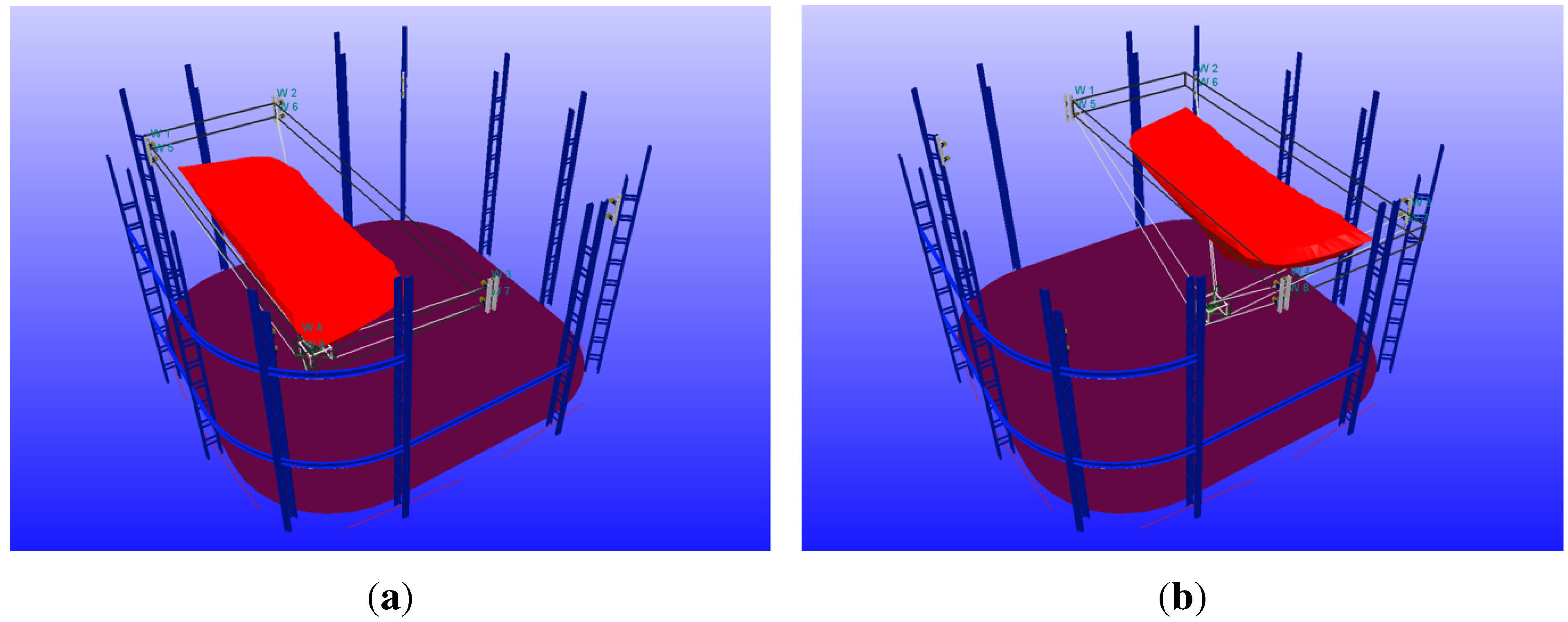
24], which was used in this scenario. The calculated wrench-feasible workspaces for both cable robots are depicted in
Figure 5. A list of technical criteria to choose feasible bounds for the cable forces was recently proposed [
25].
Figure 5.
Calculated wrench-feasible workspace for the left (a) and right (b) cable robot integrated in the installation environment.
Figure 5.
Calculated wrench-feasible workspace for the left (a) and right (b) cable robot integrated in the installation environment.
4.2. Inverse Kinematics
Since a cable robot’s mobile platform is only positioned and orientated by changing the cable lengths
, it is necessary to ensure that the desired pose can be reached with the available cable length. For a workspace of dimensions roughly
, the diagonal distance is about
, which adds to several meters between the last pulley and the actual winch, making the overall cable length varying between roughly
and up to
, depending on the investigated cable. Determining the
i-th cable length
for any given pose can be done by solving the vector loop:
where
is the
i-th cable’s length,
is the vector of the
i-th cable,
is the
i-th winch attachment point,
the attachment point of cable
i on the platform,
r the platform’s position in global coordinates and
R is the local rotation of the mobile platform frame. Additionally, every cable has a fixed length offset, which is the length of the cable from
past further pulleys to the winch, varying from cable to cable.
However, the cables used for suspending this entertainment robot require a significant bending radius. Therefore, pulleys are used to guide the cables, and the kinematic modeling becomes more intricate [
26]. This implicates changes to Equation (
16); see
Figure 6,
Figure 6.
Kinematic loop of i-th cable taking into account a pulley with non-negligible radius.
Figure 6.
Kinematic loop of i-th cable taking into account a pulley with non-negligible radius.
Using Equation (
18), every cable’s length can be determined for every pose of the trajectory as mentioned in
Section 2.3, providing the cable robot control system with the necessary commands to perform the designed movement.
4.3. Velocity and Acceleration
Velocity verification of the designed cable robot’s path is performed two-fold, for Cartesian velocities and for joint-space velocities. Performing two-fold validation of velocities is necessary because of the limitations of the mobile platform velocity imposed by the specifications, but also due to the limitations of the cable velocities imposed by the capabilities of the winches. Furthermore, the use of Bryant angles in orientation planing imposes a distortion of the orientation space, the effect of which can be seen in the cable length. Therefore, it is crucial to test the cable velocities and accelerations to prevent drive-train overload.
4.3.1. Velocity Verification
Verification of the platform’s Cartesian velocities compliance with its velocity limits can be done straightforwardly using the finite difference approximation of adjacent Cartesian poses:
In order to determine the cable velocities, the differentiation of the cable length with respect to time
t is required, which can be obtained from Equation (
18) as:
Since the mobile platform is a rigid body and the position of the cable contact points
is time-invariant, Equation (
23) can be simplified to:
where
is the cable unit vector,
the platform’s Cartesian velocity and ω the platform’s rotational velocity. Given Equation (
24), the feasibility of the cable velocity limits can be verified by checking each cable’s velocity separately.
4.3.2. Acceleration Verification
To determine the compliance of joint-space accelerations, Equation (
24) can be differentiated once more with respect to time
t, yielding:
Every entry of
obtained by means of Equation (
25) can then independently be checked on compliance with the maximum allowed joint-space acceleration.
4.4. Collision Detection
Since cables are attached to the mobile platform to manipulate its pose, the cables will always be inside the installation space and, even worse, inside the workspace. Intuitively, cable collision is ineluctable; however, the risk of cable collision with either the other cables or the environment can be reduced by proper mobile platform design. Nevertheless, it cannot be avoided purely by changing the cable robot design, but must be avoided in the path planning phase to provide the path designers with a proper feedback. Furthermore, collision of the mobile platform and the environment must be avoided to not destroy either part or to cause any danger to the audience.
For every given pose of the trajectory, three tests are performed, (i) cable-cable collision detection, (ii) cable-platform collision detection, (iii) platform-environment collision detection.
4.4.1. Cable-Cable Collision Detection
Assuming massless cables in an ideal tightened state, each cable runs at a straight line from its anchor point
on the mobile platform to its (adjusted) anchor point on the pulley
; see
Figure 6. Given a mobile platform pose
r, we can calculate the cable vector according to Equation (
18). Collision of cable
i and
j requires their respective cable vectors to intersect between the span points
and
and
and
, respectively,
The distance between two cables is then calculated using:
where
is the connection of the adjusted pulley anchor points and
and
are the cable attachment points on the mobile platform of the
i-th and
j-th cable, respectively. Given
d from Equation (
27) provides a value smaller than the defined minimum safety distance
, it is necessary to ensure that the intersection point does not lie outside the permissible region,
i.e., it must be between mobile platform and pulleys. This can be checked straightforward by calculating:
with:
4.4.2. Cable-Platform Collision Detection
Given the shape of the mobile platform as shown in
Figure 7a, it is obvious that the mobile platform has a hull, which might collide with the cables in certain poses.
Figure 7.
Designed mobile platform of the cable robot: (a) CAD rendering of the mobile platform design used at the EXPO show with the marking of the visible cable attachment points and the final mobile platform; (b) the platform of a cable robot in the German Pavilion at the EXPO 2015.
Figure 7.
Designed mobile platform of the cable robot: (a) CAD rendering of the mobile platform design used at the EXPO show with the marking of the visible cable attachment points and the final mobile platform; (b) the platform of a cable robot in the German Pavilion at the EXPO 2015.
Algorithms for the detection of cable-platform collision reach from look-up tables to on-line calculation of collision. Still, due to the limitations of available memory, on-line calculation is implemented only for the trajectory planning interface. Similarly to the algorithms of
Section 4.4.1, collision is determined by calculating the distance between the discretized mobile platform hull and the
i-th cable via:
If , then there is the collision or at least the near collision of the cable and mobile platform for the given pose and cable i and some point j on the mobile platform hull. This algorithm supplants checking every vertex for the intersection with the cable vector in terms of computational speed and accuracy.
4.4.3. Platform-Environment Collision Detection
Ensuring planned paths do not cause the mobile platform to collide with its environment is primarily performed with a bounding box test on the current mobile platform pose x given the dimensions of the platform. If some of the bounding box edges are outside the valid space, this section is then further investigated. If none of the points of the bounding box are outside the predefined space, the pose will not cause any collision of the mobile platform with its environment.
5. Results
In the German Pavilion, the cable velocities and accelerations are limited to 1.2 m·s
−1 and 1 m·s
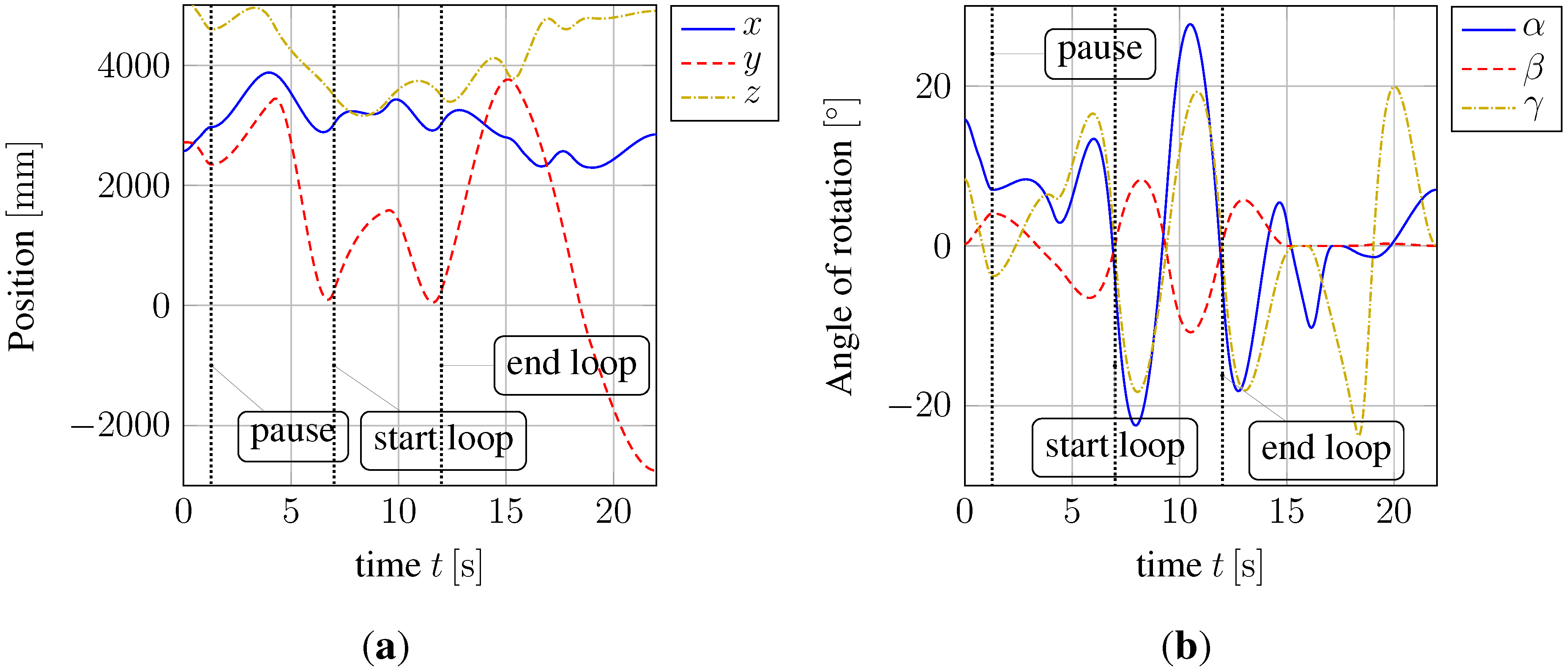
−2 for safety reasons, whereas the maximum cable forces are set to 2.45 kN. In order to demonstrate the path planning tool, a complex test trajectory for one of the cable robots is created, which exploits the extreme positions of the workspace and also includes manipulations of the robot’s orientation. This show consists of three sequences and takes about 22 s. The sequences take 7 s, 5 s and 10 s and are connected. It should be noted that the first sequence additionally contains a pause at time point 1.4 s, whereas the second sequence is defined as a so-called loop sequence.
Figure 8 illustrates the Cartesian coordinates and the Cardan angles of the robot’s mobile platform of the whole show. All trajectories are smooth, which is desired in order to get a visually-appealing curve. Note that the mobile platform position in the
z-direction varies between roughly 3 m and 5.2 m, whereas the travel in the
y-direction is about 6.5 m. We recapitulate that a pause is a special point in the show defined by no velocities in all coordinates to obtain flexibility in the show. A loop sequence is defined as a relatively described sequence with the same start and end conditions and is permanently repeated until an external signal is triggered. Both pause and loop properties are fulfilled as shown in the figures.
After planning the Cartesian coordinates, the joint-space coordinates, like cable length and cable velocity, are computed by solving Equation (
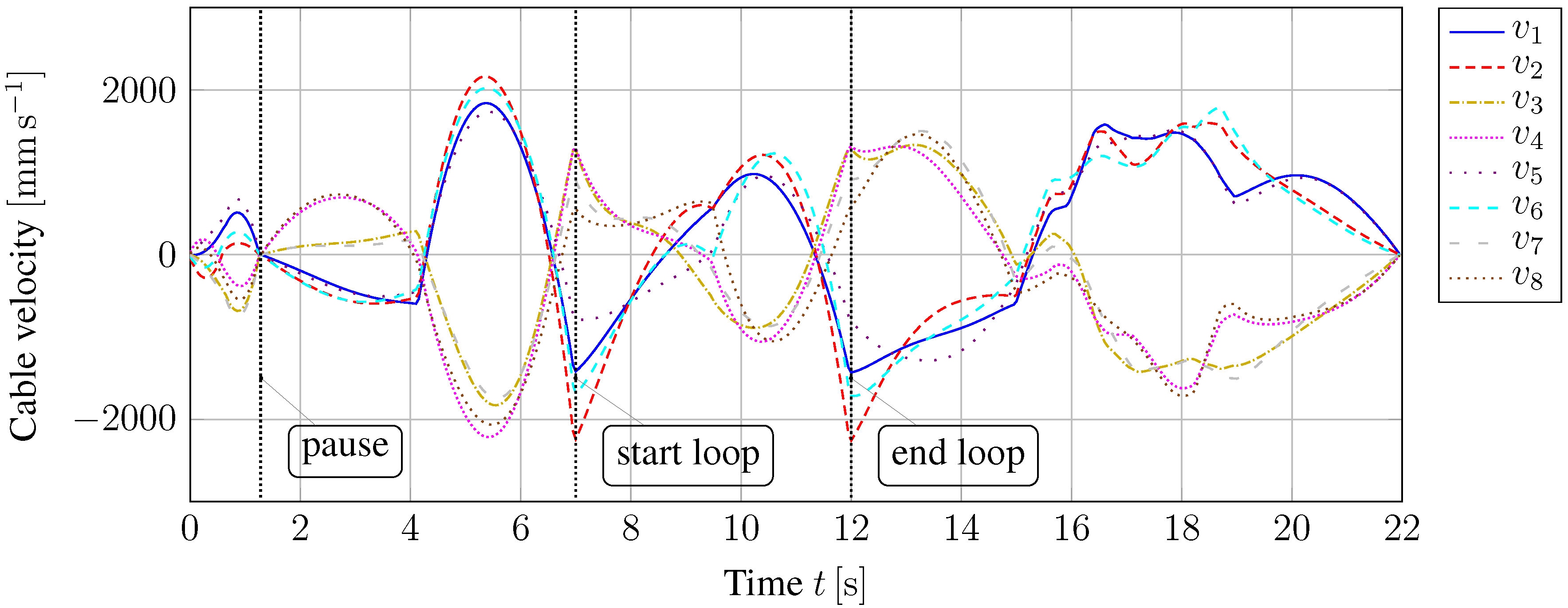
18). Satisfying smooth trajectories in position and orientation also leads to smooth trajectories in cable length and cable velocity, which is confirmed by
Figure 9 and
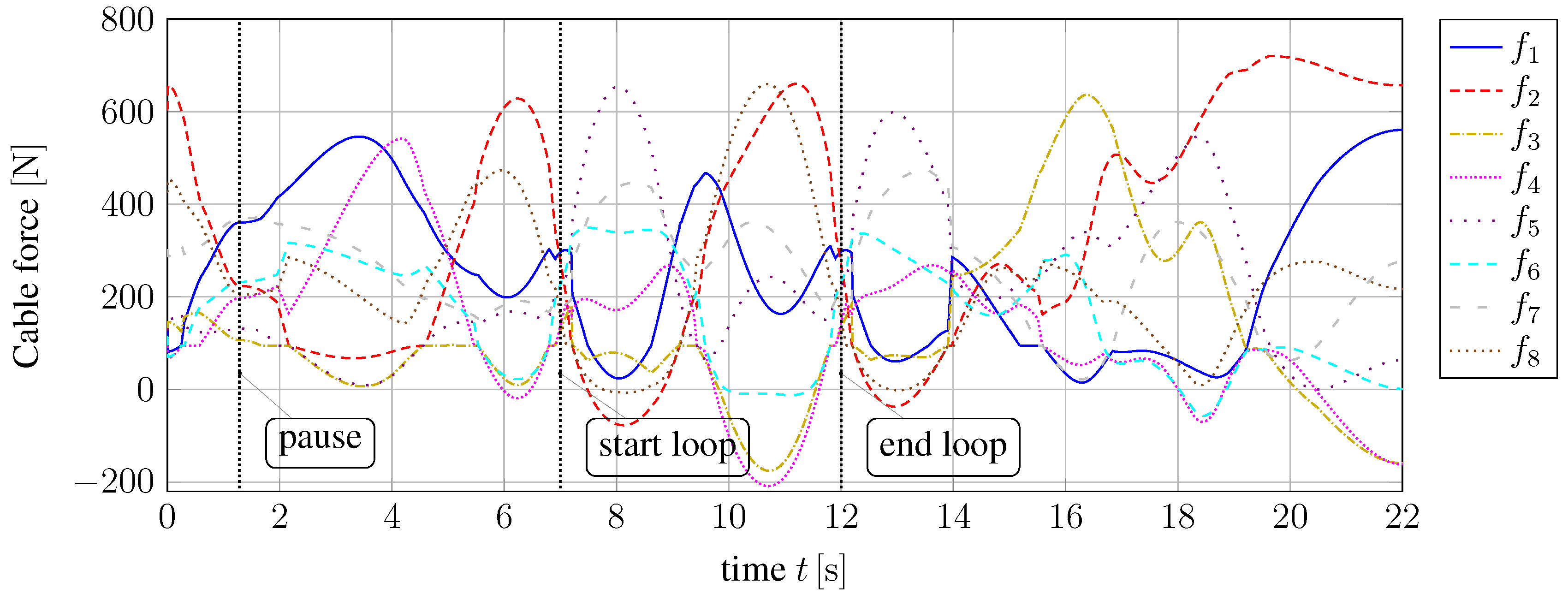
Figure 10. As expected, the conditions for pause and loop are satisfied, as well.
Figure 11 displays the cable force distribution, which is also smooth and bounded by 700 N, respectively -200 N.
Figure 8.
Test trajectory with (a) Cartesian coordinates x, y, z and (b) Cardan angles α, β and γ of the robot’s platform.
Figure 8.
Test trajectory with (a) Cartesian coordinates x, y, z and (b) Cardan angles α, β and γ of the robot’s platform.
Figure 9.
Cable length .
Figure 9.
Cable length .
Figure 10.
Cable velocity .
Figure 10.
Cable velocity .
Figure 11.
Cable force .
Figure 11.
Cable force .
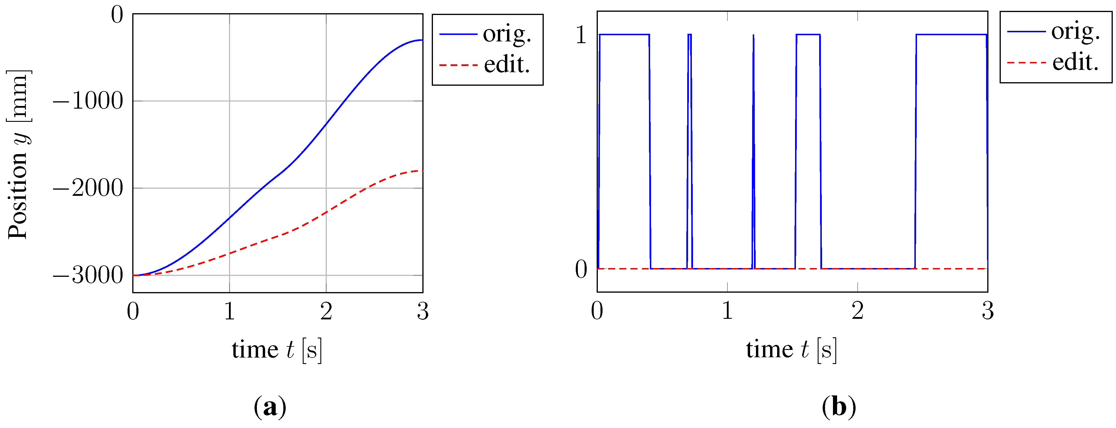
The functionality of the path verification tests is demonstrated on a second short trajectory depicted in
Figure 12a, whereas the Cartesian coordinates in the
x- and
z-direction are kept constant. For this trajectory, all mentioned tests are performed, and their results are illustrated in
Figure 12b. Obviously, the original trajectory leads to an exceeding of the cable acceleration limits. Shortening the trajectory in the
y-direction for 1.5 m, it can be seen that no test failed anymore, and hence, the cable acceleration limitations are fulfilled.
Figure 12.
Demonstration of the functionality of the path verification results with a second test trajectory. (a) Cartesian coordinate y in of the original and edited curve; (b) path verification results of original and edited curve (0, no test failed; 1, cable acceleration test failed).
Figure 12.
Demonstration of the functionality of the path verification results with a second test trajectory. (a) Cartesian coordinate y in of the original and edited curve; (b) path verification results of original and edited curve (0, no test failed; 1, cable acceleration test failed).
Besides verifying the functional conformity of the developed validation algorithms, also technical benchmarking was performed. This is necessary to verify that test execution time is not too long to hinder the interactive design of the trajectories. Benchmarking the tests was performed one test case at a time and additionally with all tests combined running at 10,000 iterations per test case. With a number of 2200 poses, the examined trajectory is rather short compared to the final show; however, it is a reasonable length of one sequence designed by the artists.
The results shown in
Table 1 illustrate rather quick execution of every test performed on the whole trajectory, as well as an acceptable execution time of all tests at once. This is favorable for using the validation interactively as the user drags a trajectory’s control point. It must be mentioned that it is not necessary to run every test over the full trajectory every time a change is made. Limiting the range of executing the tests around the set of modified trajectory points drastically reduces the execution time.
Table 1.
Benchmarking results of the developed tests run over the full trajectory presented in this paper.
Table 1.
Benchmarking results of the developed tests run over the full trajectory presented in this paper.
| Test Case | Execution Time (ms) |
|---|
| Wrench Feasibility | 194.5 |
| Reachability | 21.1 |
| Excessive Cartesian Velocities | 20.5 |
| Excessive Cartesian Acceleration | 20.0 |
| Cable-Cable Collision | 23.0 |
| Cable-Platform Collision | 27.3 |
| Excessive Pulley Deflection | 26.0 |
| Excessive Joint Velocity | 22.4 |
| Excessive Joint Acceleration | 22.2 |
| Excessive Motor Torque | 30.0 |
| All Tests | 423.6 |
6. Conclusions
The design and programming of cable-driven parallel robots in the German Pavilion at the EXPO 2015 has been presented. On the one hand, the proposed path planning software enables an intuitive planning of complex trajectories and produces a visually soft and smooth movement. On the other hand, the workspace and technical limitations, like cable velocities and forces, are taken into account. At first, the mathematical description, interpolation and export of a path has been introduced. Afterwards, the robot design has been developed based on a workspace estimation. Furthermore, the software considers the technical feasibility and the compliance with the limitations by executing several complex path verifications, which have been studied in detail. Simulation results have illustrated that a visually-appealing and technically-feasible show can be exported due to the fact that the trajectories both in cable length and cable velocity are smooth and all limitations are considered. The proposed software has been used for creating the trajectories of the cable robots for the show in the German Pavilion at the EXPO 2015 in Milan, which runs about 40 times a day from May 2015 to October 2015 in front of a great audience and also shows the technical feasibility and robustness of such a giant cable robot.
Acknowledgments
The University of Stuttgart, as well as the Ministerium für Wissenschaft, Forschung und Kunst Baden-Württemberg financially supported the research for this project, and these contributions are highly appreciated. We also want to thank Milla & Partner for their invitation of being part of the EXPO team, and especially, we want to acknowledge the many discussions with Ingo Kaske and Ulrich Kunkel, which made the great show in the German Pavilion technically possible.
Author Contributions
Fabian Schnelle and Peter Eberhard developed the path planning tool with the functionalities to plan, modify and export trajectories. Philipp Tempel and Andreas Pott provided the workspace estimation and path verifications which are performed in the proposed tool.
Conflicts of Interest
The authors declare no conflict of interest.
References
- Landsberger, S.E. A New Design for Parallel Link Manipulators. Master’s Thesis, Massachusetts Institute of Technology, Cambridge, MA, USA, 1985. [Google Scholar]
- Dagalakis, N.G.; Albus, J.S.; Wang, B.L.; Unger, J.; Lee, J.D. Stiffness study of a parallel link robot crane for shipbuilding applications. ASME J. Mech. Des. 1989, 111, 183–193. [Google Scholar] [CrossRef]
- Albus, J.S.; Bostelman, R.V.; Dagalakis, N.G. The NIST ROBOCRANE. J. Res. Natl. Inst. Stand. Technol. 1992, 97, 373–385. [Google Scholar] [CrossRef]
- Pott, A.; Meyer, C.; Verl, A. Large-scale assembly of solar power plants with parallel cable robots. In Proceedings of the 41st International Symposium on Robotics (ISR) and 2010 6th German Conference on Robotics (ROBOTIK), Munich, Germany, 7–9 June 2010; pp. 1–6.
- Pott, A. An algorithm for real-time forward kinematics of cable-driven parallel robots. In Advances in Robot Kinematics; Springer: Berlin, Germany, 2010. [Google Scholar]
- Merlet, J.P. Kinematics of the wire-driven parallel robot MARIONET using linear actuators. In Proceedings of the IEEE International Conference on Robotics and Automation, Pasadena, CA, USA, 19–23 May 2008.
- Otis, M.J.D.; Comtois, S.; Laurendeau, D.; Gosselin, C. Human safety algorithms for a parallel cable-driven haptic interface. Adv. Intell. Soft Comput. 2010, 83, 187–200. [Google Scholar]
- Otis, M.J.D.; Perreault, S.; Nguyen Dang, T.L.; Lambert, P.; Gouttefarde, M.; Laurendeau, D.; Gosselin, C. Determination and Management of Cable Interferences Between Two 6-DOF Foot Platforms in a Cable-Driven Locomotion Interface. Man Cybern. Syst. 2009, 39, 528–544. [Google Scholar] [CrossRef]
- Baoyan, D.; Qiu, Y.Y.; Fushun, Z.; Zi, B. Analysis and experiment of the feed cable-suspended structure for super antenna. In Proceedings of the IEEE/ASME International Conference on Advanced Intelligent Mechatronics, Xi’an, China, 2–5 July 2008; pp. 329–334.
- Blender Online Community: Blender—A 3D Modeling and Rendering Package. Blender Foundation, Blender Institute: Amsterdam, The Netherlands. Available online: http://www.blender.org (accessed on 23 June 2015).
- Roberson, R.E.; Schwertassek, R. Dynamics of Multibody Systems; Springer: Berlin, Germany, 1988. [Google Scholar]
- Mortenson, M.E. Geometric Modeling; John Wiley & Sons: New York, NY, USA, 1985. [Google Scholar]
- Verhoeven, R. Analysis of the Workspace of Tendon-Based Stewart Platforms. Ph.D. Thesis, University of Duisburg-Essen, Duisburg, Germany, 2004. [Google Scholar]
- Du Huynh, Q. Metrics for 3D rotations: Comparison and analysis. J. Math. Imaging Vis. 2009, 35, 155–164. [Google Scholar] [CrossRef]
- Pott, A.; Boye, T.; Hiller, M. Design and optimization of parallel kinematic machines under process requirements. In Proceedings of the 5th Chemnitz Parallel Kinematics Seminar, Chemnitz, Germany, 25–26 April 2006; pp. 193–212.
- Yao, R.; Tang, X.; Wang, J.; Huang, P. Dimensional optimization design of the four-cable-driven parallel manipulator in FAST. IEEE/ASME Trans. Mechatron. 2010, 15, 932–941. [Google Scholar] [CrossRef]
- Guilin, Y.; Pham, C.B.; Yeo, S.H. Workspace performance optimization of fully restrained cable-driven parallel manipulators. In Proceedings of the IEEE/RSJ International Conference on Intelligent Robots and Systems, Beijing, China, 9–15 October 2006; pp. 85–90.
- Hay, A.M.; Snyman, J.A. Optimization of a planar tendon-driven parallel manipulator for a maximal dextrous workspace. Eng. Optim. 2005, 37, 217–236. [Google Scholar] [CrossRef]
- Gouttefarde, M.; Merlet, J.P.; Daney, D. Wrench-feasible workspace of parallel cable-driven mechanisms. In Proceedings of the IEEE International Conference on Robotics and Automation, Roma, Italy, 10–14 April 2007; pp. 1492–1497.
- Mikelsons, L.; Bruckmann, T.; Schramm, D.; Hiller, M. A real-time capable force calculation algorithm for redundant tendon-based parallel manipulators. In Proceedings of the IEEE International Conference on Robotics and Automation, Pasadena, CA, USA, 19–23 May 2008.
- Bruckmann, T.; Pott, A.; Hiller, M. Calculating force distributions for redundantly actuated tendon-based Stewart platforms. In Advances in Robot Kinematics; Springer: Berlin, Germany, 2006; pp. 403–412. [Google Scholar]
- Snyman, J.A.; Hay, A.M. Analysis and optimization of a planar tendon-driven parallel manipulator. In Advances in Robot Kinematics; Kluwer Academic Publishers: Dordrecht, The Netherlands, 2004; pp. 303–312. [Google Scholar]
- Oh, S.R.; Agrawal, S.K. Cable-suspended planar parallel robots with redundant cables: Controllers with positive cable tensions. In Proceedings of the IEEE International Conference on Robotics and Automation, Taipei, Taiwan, 14–19 September 2003; Volume 3, pp. 3023–3028.
- Pott, A.; Bruckmann, T.; Mikelsons, L. Closed-form force distribution for parallel wire robots. In Computational Kinematics; Springer: Berlin, Germany, 2009; pp. 25–34. [Google Scholar]
- Pott, A. On the limitations on the lower and upper tensions for cable-driven parallel robots. In Advances in Robot Kinematics; Springer: Berlin, Germany, 2014; pp. 243–251. [Google Scholar]
- Pott, A. Influence of pulley kinematics on cable-driven parallel robots. In Advances in Robot Kinematics; Springer: Berlin, Germany, 2012; pp. 197–204. [Google Scholar]
© 2015 by the authors; licensee MDPI, Basel, Switzerland. This article is an open access article distributed under the terms and conditions of the Creative Commons Attribution license (http://creativecommons.org/licenses/by/4.0/).
