Graphite Dendrites in Cast Iron and Their Fundamental Role in the Control of Morphology to Obtain Aero-Eutectic Graphite


Abstract
:1. Introduction
1.1. About the Objective of This Work: Aero-Eutectic Graphite (AEG)
1.2. Briefly, About the Basic Graphite Crystallography and Derived Properties
1.3. About Some of Our Theoretical Guides
2. Materials and Methods
2.1. AEG Manufacturing
2.2. Electrochemical AEG Test: Li-O2 Battery
3. Results
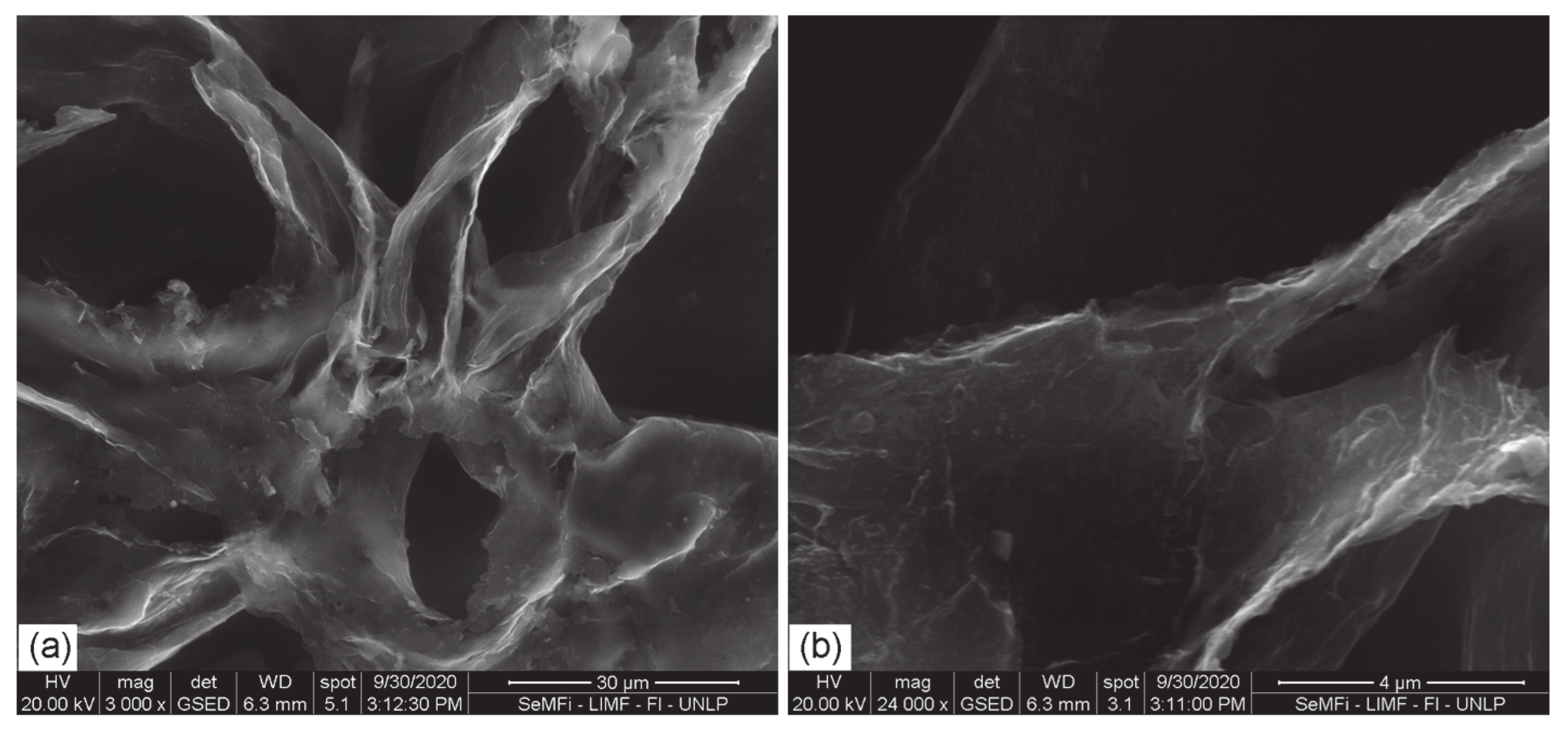
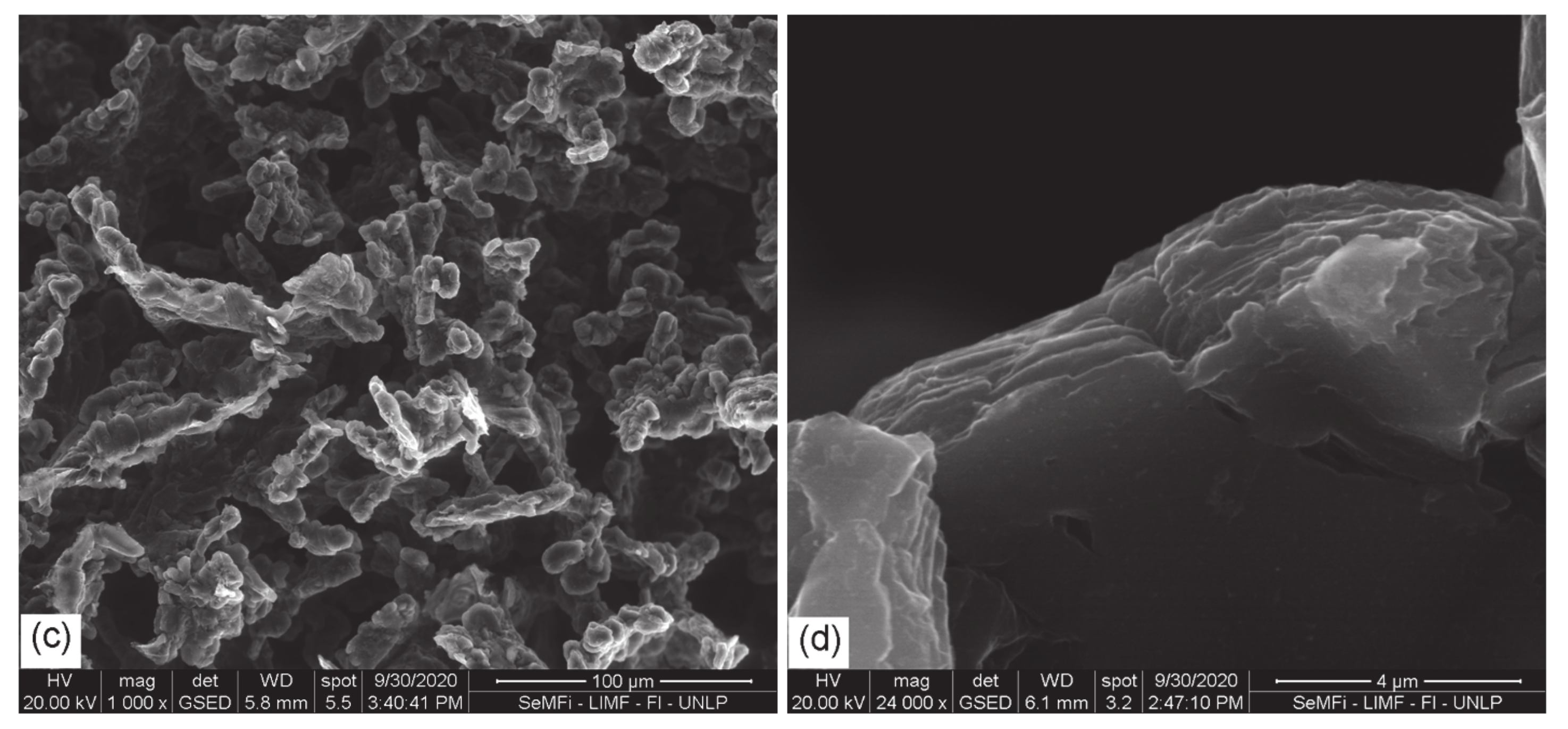
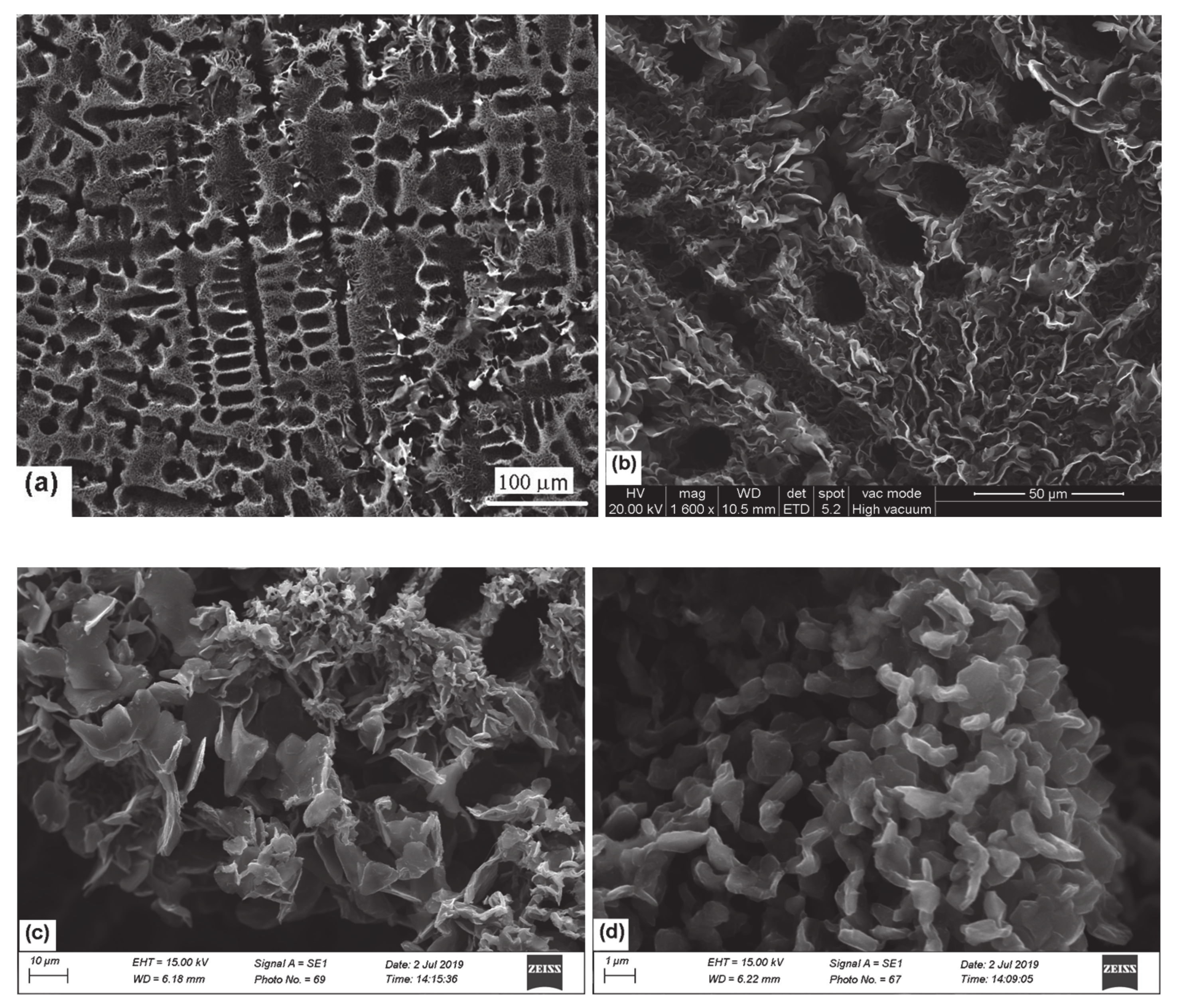
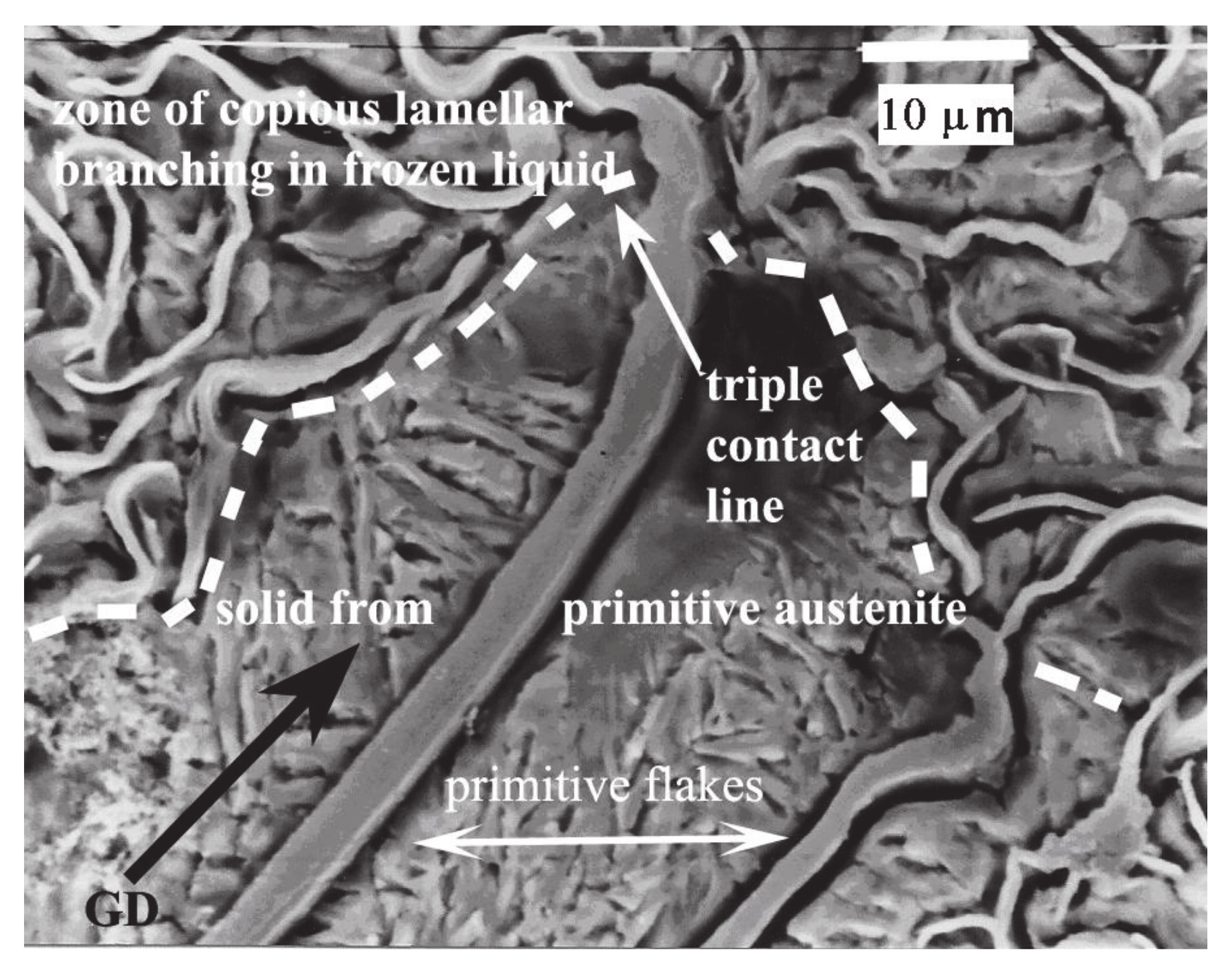
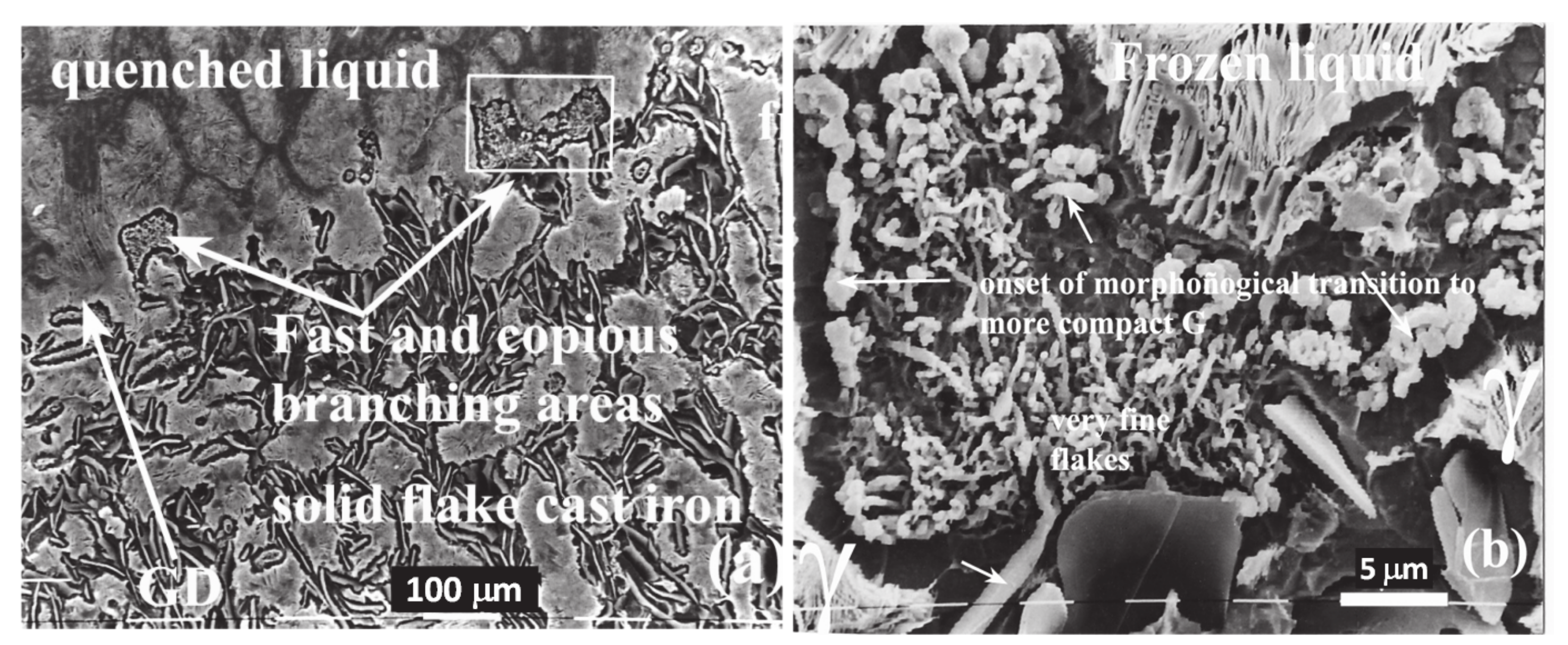
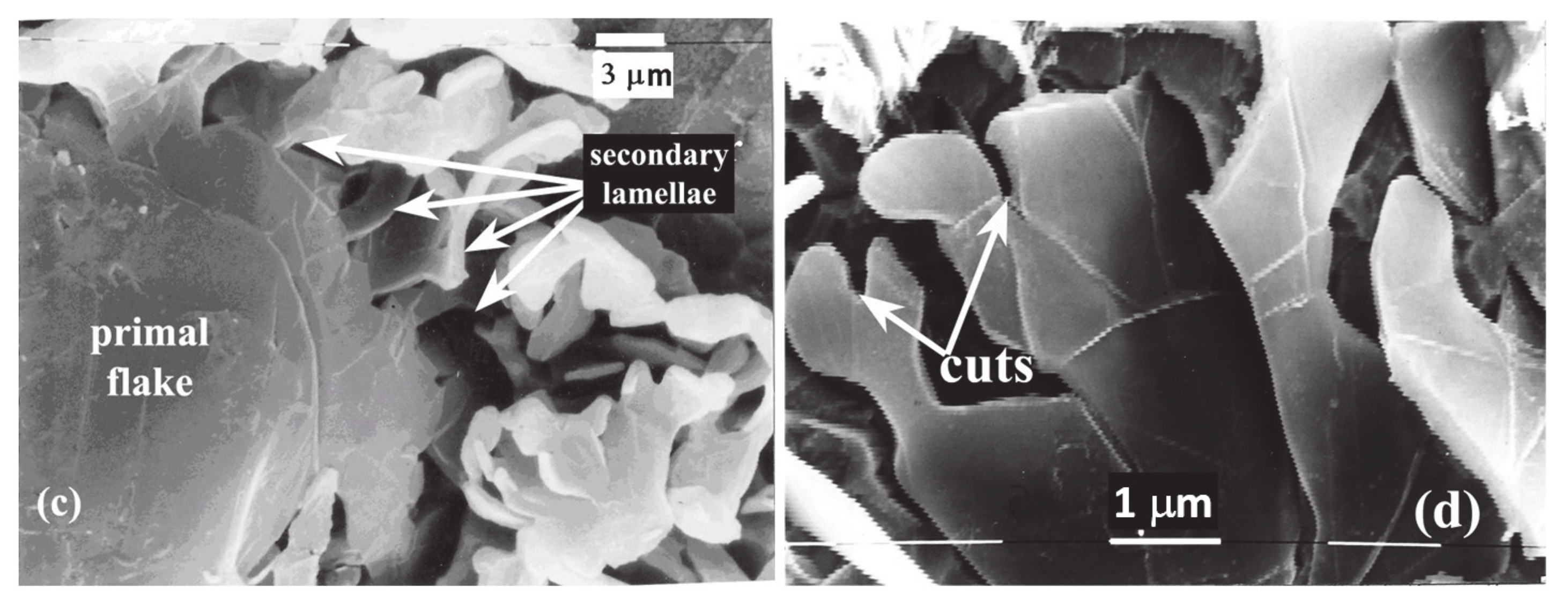
3.1. SEM
3.2. BET and X-Ray Diffraction
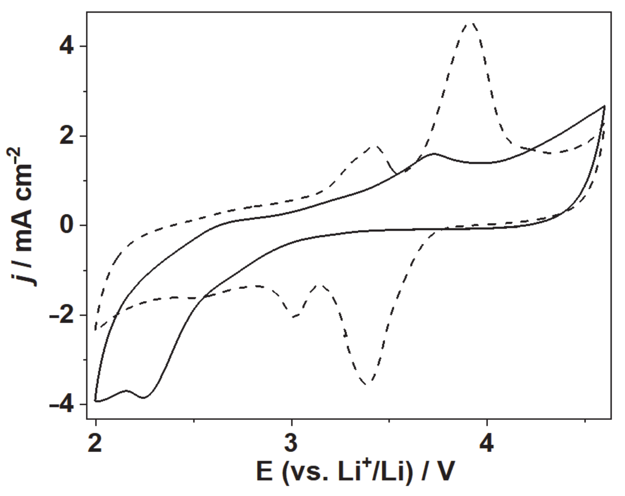
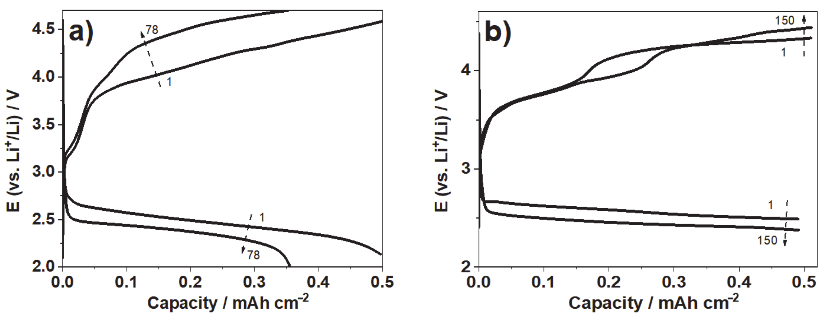
3.3. Cyclic Voltammetry and Discharging Profiles of Li-O2 Battery With LDG-AEG Cathode
4. Discussion
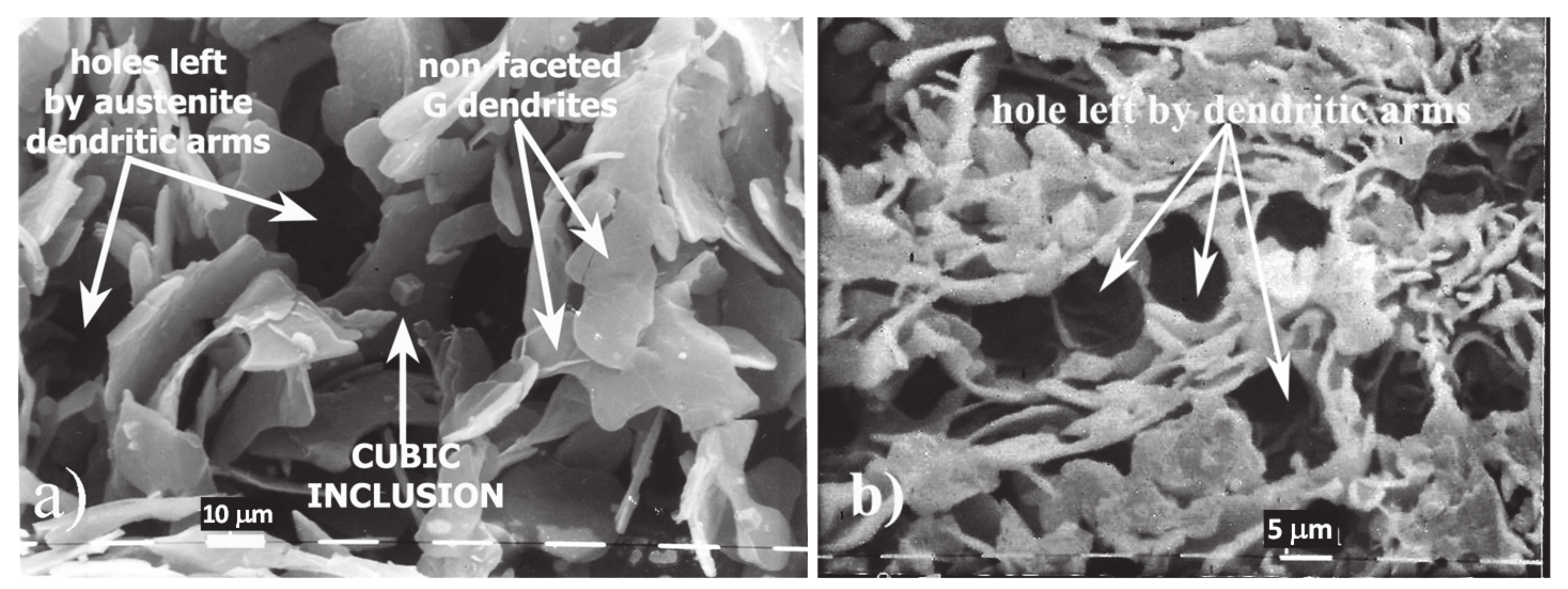
4.1. Evidence of Non-Faceted Growth in LG
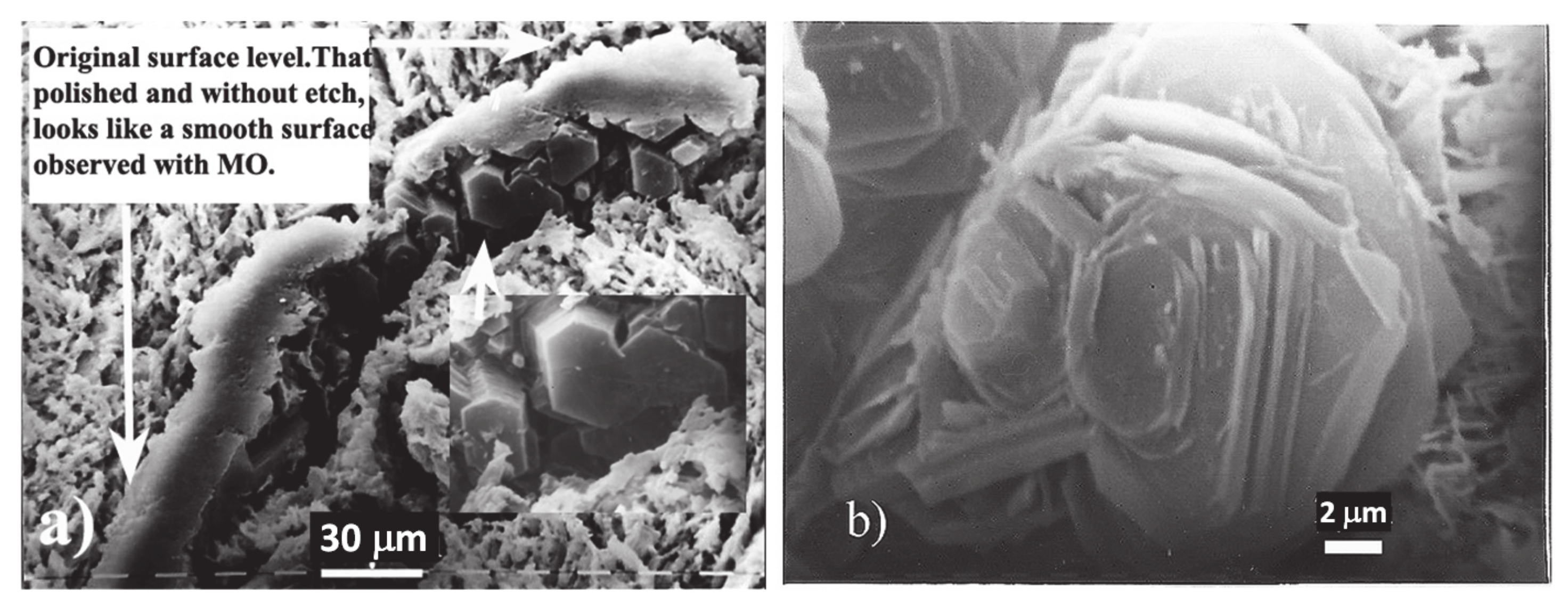
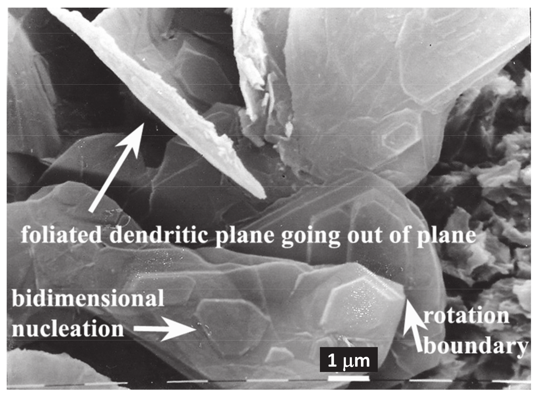
4.2. Evidence of Faceted Dendritic Growth in GC
4.3. AEG As Cathode in Li-O2 Battery
5. Conclusions
Author Contributions
Funding
Institutional Review Board Statement
Informed Consent Statement
Data Availability Statement
Acknowledgments
Conflicts of Interest
Abbreviations
| AEG | Aero-Eutectic Graphite |
| AEG-CG | Aero-Eutectic graphite from compacted graphite |
| AEG-LGD | Aero-Eutectic graphite from Type D graphite |
| BET | Brunauer-Emmett-Teller |
| CG | Compacted graphite |
| FCC | Face centered cubic |
| LAG | Lamellar graphite Type A |
| LDG | Laminar graphite Type D |
| LEG | Lamellar graphite Type E |
| LG | Lamellar graphite |
| LG-AEG | Aero-Eutectic graphite lamellar graphite |
| LiTFSI | Lithium bis-(trifluoromethanesulfonyl)-imide |
| MM | Morphological Modification |
| n-f | non-faceted |
| NG | Nodular graphite |
| OER | Oxygen evolution reaction |
| OM | Optical microscopy |
| ORR | Oxygen reduction reaction |
| RM | Redox mediator |
| Triglyme | Triethylene glycol dimethyl ether |
| γ | Austenite |
References
- Su, B.L.; Sánchez, C.; Yang, X.-Y. Hierarchically Structured Porous Materials: From Nanoscience to Catalysis, Separation, Optics, Energy, and Life Science, 1st ed.; Wiley VCH: Weinheim, Germany, 2012. [Google Scholar]
- Gregorutti, R.W.; Tesio, A.Y.; Gómez-Cámer, J.L.; Roviglione, A.N. Synthesis and characterization of aero-eutectic graphite obtained by solidification and its application in energy storage: Cathodes for lithium oxygen batteries. Electron. Mater. 2020, 1, 3. [Google Scholar] [CrossRef]
- McNaught, A.D.; Wilkinson, A. Compendium of Chemical Terminology, 2nd ed.; The “Gold Book”; Blackwell Scientific Publications: Oxford, UK, 1997; ISBN 0-9678550-9-8. [Google Scholar] [CrossRef]
- Holcombe, C.E. USAEC Oak Ridge Y-12 Plant, Report Y 1887; National Technical lnformation Service: Springfield, VA, USA, 1973. [Google Scholar]
- Roviglione, A.N.; Hermida, J.D. Mechanism of formation of different cast iron graphite structures. In Proceedings of the 72nd National Conference of the Argentine Physical Association (AFA), San Carlos de Bariloche, Argentina, 28 September–2 October 1987. [Google Scholar]
- Delavignette, P.; Amelinckx, S. Dislocation patterns in graphite. J. Nuclear Mater. 1962, 5, 17–66. [Google Scholar] [CrossRef]
- Double, D.D.; Hellawell, A. Cone-helix growth forms of graphite. Acta Metall. 1974, 22, 481–487. [Google Scholar] [CrossRef]
- Roviglione, A.N.; Hermida, J.D. Rhombohedral graphite phase in nodules from ductile cast iron. Proc. Mater. Sci. 2015, 8, 924–933. [Google Scholar] [CrossRef] [Green Version]
- Kelly, B.T. Physics of Graphite; Applied Science Publishers: London, UK, 1981. [Google Scholar]
- Saratovkin, D.D. Dendritic Crystallization; Consultants Bureau Transl.: New York, NY, USA, 1959. [Google Scholar]
- Liu, S.; Loper, C.R. The formation of kish graphite. Carbon 1991, 29, 547–555. [Google Scholar] [CrossRef]
- Roviglione, A.N.; Biloni, H. Modificación de la morfología de crecimiento de la fase grafito durante la solidificación unidireccional de la fundición de hierro gris. PARTE I: “Solidificación Unidireccional. modificación in-situ, congelado de la interfaz Sólido-Líquido y Caracterización de Microestructuras”. In Actas Jornadas Metalúrgicas SAM’91; II ALAMET’91 ed.; Sociedad Argentina de Metales: Buenos Aires, Argentina, 1991. [Google Scholar]
- Roviglione, A.N.; Biloni, H. Unidirectional solidification of cast iron: Morphological changes of graphite due to in-situ modification. In Proceedings of the Fifth International Symposium on the Physical Metallurgy of Cast Iron (SCI-5), Nancy, France, 3–5 October 1994; pp. 369–376. [Google Scholar]
- Roviglione, A.N.; Hermida, J.D. A new unidirectional solidification method to study gray cast iron. Metall. Mater. Trans. B 2002, 33, 235–241. [Google Scholar] [CrossRef]
- Roviglione, A.N.; Hermida, J.D. From flake to nodular: A new theory of morphological modification in gray cast iron. Metall. Mater. Trans. B 2004, 35, 313–330. [Google Scholar] [CrossRef]
- Stefanescu, D.M.; Huff, R.; Alonso, G.; Larrañaga, P.; De La Fuenta, E.; Suarez, R. On the crystallization of compacted and chunky graphite from liquid multicomponent Iron-Carbon-Silicon-based melts. Metall. Mater. Trans. A 2016, 47, 4012–4023. [Google Scholar] [CrossRef]
- ASTM A247-19. Standard Test Method for Evaluating the Microstructure of Graphite in Iron Castings; ASTM International: West Conshohocken, PA, USA, 2019. [Google Scholar] [CrossRef]
- Park, J.S.; Verhoeven, J.D. Transitions between type A flake, type D flake, and coral graphite eutectic structures in cast irons. Metall. Mater. Trans. A 1996, 27, 2741–2753. [Google Scholar] [CrossRef]
- Larrañaga, P.; Sertucha, J.; Loizaga, A.; Suarez, R.; Stefanescu, D.M. Gray cast iron with high austenite-to-eutectic ratio. Part III-High strength, low hardness, high carbon equivalent gray iron with superfine graphite. Am. Found. Soc. 2012, 120, 347–353. [Google Scholar]
- Hernando, J.C.; Diószegi, A. On the primary solidification of compacted graphite iron: Microstructure evolution during isothermal coarsening. Mater. Sci. For. 2018, 925, 90–97. [Google Scholar] [CrossRef] [Green Version]
- ASM. Cast Iron Science and Technology; Doru, M.S., Ed.; ASM: Almere, The Netherlands, 2017. [Google Scholar]
- Roviglione, A.N. An useful technique for studying graphite in cast iron. Mater. Charact. 1993, 31, 209–216. [Google Scholar] [CrossRef]
- Bender, C.L.; Hartmann, P.; Vračar, M.; Adelhelm, P.; Janek, J. On the thermodynamics, the role of the carbon cathode, and the cycle life of the sodium superoxide (NaO2) battery. Adv. Energy Mater. 2014, 4, 1301863. [Google Scholar] [CrossRef]
- Roviglione, A.N.; Hermida, J.D. X-ray diffraction characterization of flake and compacted graphite in cast iron. Mater. Charact. 1994, 32, 127–137. [Google Scholar] [CrossRef]
- Kurz, W.; Fisher, D.J. Fundamentals of Solidification; Trans Tech. Publications: Bäch, Switzerland, 1986; pp. 111–112. [Google Scholar]
- Gregorutti, R.W.; Grau, J.E. Mechanical properties of compacted graphite cast iron with different microstructures. Inter. J. Cast Metal. Res. 2014, 27, 275–281. [Google Scholar] [CrossRef]
- Placke, T.; Siozios, V.; Schmitz, R.; Lux, S.; Bieker, P.; Colle, C.; Meyer, H.-W.; Passerini, S.; Winter, M. Influence of graphite surface modifications on the ratio of basal plane to “non-basal plane” surface area and on the anode performance in lithium ion batteries. J. Power Sour. 2012, 200, 83–91. [Google Scholar] [CrossRef]
- Olivier, J.P.; Buqa, H.; Kohs, W.; Schröttner, H.; Golob, P.; Winter, M. The Relevance of Graphite Surface Properties for Anode Performance in Lithium Ion Cells-III. Surface Area and Surface Heterogeneieties; Micromeritics Instrument Corp, Inc.: Norcross, GA, USA, 2001. [Google Scholar]
- Yuan, J.; Yu, J.-S.; Sundén, B. Review on mechanisms and continuum models of multi-phase transportphenomena in porous structures of non-aqueous Li-Air batteries. J. Power Sour. 2015, 278, 352–369. [Google Scholar] [CrossRef]
- Lim, H.-D.; Yun, Y.S.; Ko, Y.; Bae, Y.; Song, M.Y.; Yoon, H.J.; Kang, K.; Jin, H.-J. Three-dimensionally branchedcarbon nanowebs as air-cathode for redox-mediated Li-O2 batteries. Carbon 2017, 118, 114–119. [Google Scholar] [CrossRef]
- Ferrari, S.; Quartarone, E.; Tomasi, C.; Bini, M.; Galinetto, P.; Fagnoni, M.; Mustarelli, P. Investigation of ether-based ionic liquid electrolytes for Lithium-O2 batteries. J. Electrochem. Soc. 2015, 162, A3001–A3006. [Google Scholar] [CrossRef]
- Laoire, C.O.; Mukerjee, S.; Abraham, K.M.; Plichta, E.J.; Hendrickson, M.A. Influence of nonaqueous solvents on the electrochemistry of oxygen in the rechargeable lithium-air battery. J. Phys. Chem. 2010, 114, 9178–9186. [Google Scholar] [CrossRef]
- Guo, L.; Wang, J.; Ma, S.; Zhang, Y.; Wang, E.; Peng, Z. The origin of potential rise during charging of Li-O2 batteries. Sci. China Chem. 2017, 60, 1527–1532. [Google Scholar] [CrossRef]
- Lai, J.; Xing, Y.; Chen, N.; Li, L.; Wu, F.; Chen, R. A comprehensive insight into the electrolytes for rechargeablelithium–air batteries. Angew. Chem. 2019, 59, 2974–2997. [Google Scholar] [CrossRef] [PubMed]
- Tamakloe, W.; Agyeman, D.A.; Park, M.; Yang, J.; Kang, Y. Polydopamine-induced surface functionalization of carbon nanofiber for Pd deposition enabling an enhanced catalytic activity for oxygen reduction and evolution reactions. J. Mater. Chem. A 2019, 7, 7396–7405. [Google Scholar] [CrossRef]
- Mahne, N.; Schafzahl, B.; Leypold, C.; Leypold, M.; Grumm, S.; Lietgeb, A.; Strohmeier, G.A.; Wilkening, M.; Fontaine, O.; Kramer, D.; et al. Singlet oxygen generation as a major cause for parasitic reactions during cycling of aprotic lithium–oxygen batteries. Nat. Energy 2017, 2, 17036. [Google Scholar] [CrossRef] [Green Version]
- Juris, A.; Balzani, V.; Barigelletti, F.; Campagna, S.; Belser, P.; von Zelewsky, A. Ru(II) polypyridine complexes: Photophysics, photochemistry, eletrochemistry, and chemiluminescence. Coordination Chem. Rev. 1988, 84, 85–277. [Google Scholar] [CrossRef]


| Graphite | Area |
|---|---|
| Type LAG | 83.390 m2 g−1 |
| Type LDG | 89.670 m2 g−1 |
| CG | 106.277 m2 g−1 |
Publisher’s Note: MDPI stays neutral with regard to jurisdictional claims in published maps and institutional affiliations. |
© 2021 by the authors. Licensee MDPI, Basel, Switzerland. This article is an open access article distributed under the terms and conditions of the Creative Commons Attribution (CC BY) license (http://creativecommons.org/licenses/by/4.0/).
Share and Cite
Roviglione, A.N.; Tesio, A.Y.; Fungo, F.; Gregorutti, R.W. Graphite Dendrites in Cast Iron and Their Fundamental Role in the Control of Morphology to Obtain Aero-Eutectic Graphite. Minerals 2021, 11, 109. https://doi.org/10.3390/min11020109
Roviglione AN, Tesio AY, Fungo F, Gregorutti RW. Graphite Dendrites in Cast Iron and Their Fundamental Role in the Control of Morphology to Obtain Aero-Eutectic Graphite. Minerals. 2021; 11(2):109. https://doi.org/10.3390/min11020109
Chicago/Turabian StyleRoviglione, Alicia N., Alvaro Y. Tesio, Fernando Fungo, and Ricardo W. Gregorutti. 2021. "Graphite Dendrites in Cast Iron and Their Fundamental Role in the Control of Morphology to Obtain Aero-Eutectic Graphite" Minerals 11, no. 2: 109. https://doi.org/10.3390/min11020109