1. Introduction
Technology advances have greatly extended capabilities in engineering of healthcare-related systems such as body area networks (BAN) [
1], personalized health monitoring (PHM) [
2], and personal health assistants (PHA) [
3], to name a few. Multiple medical instrumentations are integrated within those systems and are able to ensure an interruptible remote monitoring of the patient’s health through Internet-based communication. Therefore, the technology enables the transition from the hospital-based and physician-centered healthcare delivery systems to home-based and patient-centered systems. However, soon not only patients but also other humans and, what is most important, the items of their everyday life will be interconnected to create a new computing infrastructure—the Internet of Things (IoT). This technological leap opens new possibilities in creating more advanced medical devices as well as medical applications. On the other hand, due to a growing proportion of senior citizens (e.g., in developed societies), there is an evident demand for the more advanced and personalized medical systems to suit user-specific needs [
2,
3,
4].
In case of healthcare, the IoT is to be considered as information-communication technology with smart features and enhanced capabilities. From this viewpoint, the IoT represents a huge infrastructure containing physical objects (e.g., medical instrumentations) that are self-identifiable to other devices and enable the communication and continuous transmission of the patient data over the nodes of a network via the Internet.
In this paper, we consider technological aspects in engineering of IoT-based PHM applications by introducing the adequate prototype and developing its software. The functionality, i.e. functional requirements of the prototype, is concerned with collecting of initial data taken from the patient’s body by medical sensors and then transferring the data over the network to a remote hospital for processing and decision-making. On the other hand, non-functional requirements of PHM are concerned with security/privacy issues (because of the transferred data may be intercepted and changed during the transfer sessions), energy-awareness (because of the use of battery-charged medical devices) and environmental factors (because of possible noises).
The diversity of medical devices (sensors), the diversity of their mode of use, and the diversity of protocols to support the integration of devices into the network of IoT applications make the design of such systems indeed challenging. The prototyping and software design automation therefore are seen as the necessity and, perhaps, as the only possible way for managing the complexity issues. Typically, the automation of design processes requires the introduction of model-driven approaches. The latter should be based on using well-proven methodologies such as Product Line Engineering (PLE) [
5].
In this paper, we propose a stack-based framework to design a medical-oriented IoT-based prototype using the model-driven approach with the focus on model transformations; the latter, in fact, means that we will attempt to introduce the automation in the design as fully as possible. We consider the functionality of the introduced framework as the main task, which contains the following sub-tasks: (1) the development of feature-based models to specify functional and non-functional requirements for the prototype; (2) model transformation (model verification, aggregation, specialization); (3) generation of executable software components for the selected prototype application.
The main contribution of the paper is (1) the stack-based computational framework to describe the overall functionality of the proposed prototype; (2) feature models describing the interaction between the functional and non-functional requirements (the latter being focused on the combined security and energy issues at the application level); and (3) an approach to connect higher-level feature models with the generation level to produce software of the IoT-oriented applications such as PHM.
The structure of the paper is as follows. In
Section 2, we analyze the related work and motivate our research. In
Section 3, we present the stack-based computational framework that includes the theoretical background and a description of the conceptual vision in solving the formulated tasks. In
Section 4, we discuss a case study to implement the computational framework using feature-based modeling and model transformation tools. In
Section 5, we present the summary, discussion, and evaluation of the proposed approach. In
Section 6, we formulate the conclusion and propose some ideas for the future work.
2. Related Work
The Internet of Things (IoT) is a new computing paradigm [
6,
7] to enable advanced capabilities in engineering various applications, including those for healthcare. Sallai [
8], for example, identifies modeling as a separate branch in the IoT research. The state-of-the-art survey [
2,
9] shows intensive research within the smart healthcare systems field and focuses on healthcare frameworks, platforms, standards, and quality attributes. The authors’ main conclusion is that the formal modeling and validation tools are enhancing the reliability and dependability properties in designing healthcare systems; however, these have not yet gained ground in real-world scenarios. Wireless sensor networks (WSN) provide a virtual layer where the information about the physical world can be accessed by any computational system. Therefore, Alcaraz et al. [
10] emphasize that WSNs are an invaluable resource for realizing the vision of the IoT in terms of integration, security, and other issues. The collection, modeling, reasoning, and distribution of context in relation to sensor data as well as context-aware computing play a critical role in IoT applications.
Adeluyi and Lee [
2] give a systematic review of the key aspects of personalized health systems. They identified the main challenges for such systems: adaptation according to the profile of the patient; requirements of quality of service and reliability; issues of privacy, security, and authentication; mobility and low energy consumption; and integration with web services. Babar et al. [
11] give an overview, analysis, and taxonomy of security and privacy challenges in IoT and propose the Security Model for the IoT. Venckauskas et al. [
12] present the energy efficient SSL protocol that ensures the maximum bandwidth and the required level of security with minimum energy consumption. Slavin et al. [
13] introduce security-requirement patterns that represent reusable security practices that software engineers can apply to improve security in their systems. The paper proposes a new method that combines an inquiry-cycle-based approach with the feature diagram notation to review relevant patterns and quickly select the most appropriate patterns for the situation. Gupta [
14] discusses the current and future security solutions for low-energy body area networks (BANs). Selimis et al. [
15] emphasize the importance to guarantee and protect the patient’s personal sensitive data obtained in wireless BANs (WBANs) and propose a new microcontroller design in order to reduce the energy consumption of the system in relation to enhancing security. Ameen et al. [
16] categorize the sensor network applications into two major categories— nonmedical and medical use (in this case, sensors can be wearable and implanted). The paper considers the security and privacy issues of such networks for healthcare applications.
The study of Hughes et al. [
17] reviews the existing research in WBAN technology, focusing on the protocol adaptation and energy efficient cross-layer design for remote continual healthcare monitoring. Venckauskas et al. [
18] present the configurable IoT prototype module to provide wide-scale experiments to obtain energy-security dependencies for various modes of IoT applications. Vu et al. [
19] describe an extensible simulation environment for the modeling of WSNs. In particular, their simulator facilitates the study of secure connectivity between sensor nodes. The simulator has five main components: a network topology model, a key establishment protocol, and an adversary model for node capture, network analysis tools, and a graphical user interface to facilitate the rapid simulation, visualization, and analysis of WSNs. Ortiz et al. [
20] consider runtime variability, which is a key technique for the success of dynamic software product lines (DSPLs), as certain applications demand reconfiguration of system features and execution plans at runtime. In this emerging research work, the authors address the problem of dynamic changes in feature models in sensor-network product families, where the nodes of the network demand dynamic reconfiguration at post-deployment time.
Fajar et al. [
21] perform feature modeling to analyze commonality and variability among the applications in terms of their features, and they visualize the analyzed commonality and variability in a tree-form diagram. The feature model provides a comprehensive view of the wireless sensor/actuator network (WSAN)-based agriculture system and helps agriculture domain experts and software engineers communicate intuitively. Moreover, the feature model will be useful for software engineers to pre-design software architecture and reusable components shared by the WSAN-based healthcare systems [
22], and Third Generation In-Ambulance Telemedicine [
23] as predominant ones now.
A large body of the following papers focuses on analyzing models and frameworks for building healthcare systems. Mehmood et al. [
24] present an ontology-based framework to expose the devices functionality for the healthcare application domain. Mavetera et al. [
25] also considers a framework that uses ontology-based view in the software development process. The ontology plays the role of the software model that bridges the communication gap between software development stages. Ruiz-Zafra et al. [
26] present a model-driven approach based on using UML to develop high-level software interfaces that enable designer to interact with wearable devices easily. This method also allows reducing risks and development efforts. Ruiz [
27] addresses the problem how to cope with the heterogeneity of sensor-based wearables devices (also used in healthcare) and to support their integration. The paper presents a model-driven approach using a meta-model that was developed for a wider system to define and specify interaction with sensors. Instances of the resulting models being derived from the proposed meta-model are specified in a custom language called the wearable markup language. Kim et al. [
28] present a model that uses ontology-based healthcare context information to implement a ubiquitous environment. The model is used to extract and classify the healthcare services using the context information by considering medical references and service environments. Benerjee et al. [
29] consider a model-driven approach for a pervasive healthcare monitoring system that uses verified body worn medical sensors and smart phones. The latter are acting as base stations in Body Sensor Networks (BSN). The main focus is taken to a high level specification of requirements and generation of both the sensor and smart phone code. Case studies relate to energy efficiency and mobility aware network reliability, showing whether the resulting implementation satisfies the requirements set forth in the design phase.
Motivation of our research. The provided literature review is by no means comprehensive due to the broadness of the topics and the extremely intensive research activities in the field. The obtained facts have enabled us to motivate our research and conclude as follows. The IoT-oriented research in healthcare is very active with a variety of introduced proposals. A great deal of the proposals focuses on model-driven design frameworks, security, privacy, and energy issues in developing the applications in this field. These issues are indeed challenging even in the case when they are treated separately. In addition, in many IoT solutions, they are common and not dependent on the type of application. If we want to enhance the quality of service of those applications, we need to consider the synergistic effect of the energy-security and environmental factors on the overall functionality of the application [
30]. Such a vision requires the use of systematic approaches and adequate methodologies. Though there are many solutions proposed in the literature on security and energy issues, so far, little is known about how those factors are to be integrated into the application software and the overall design stream. Due to the increased complexity of the applications, modeling and model-driven transformations should be seen as a relevant solution when the main focus is the design prototyping, automation and reuse. Therefore, in the next sections, we introduce and discuss a computational framework and its implementation as a part of the modern design methodologies in creating IoT-oriented PHM applications with the capabilities of reuse through adaptation and personalization.
3. Computational Framework: A Stack-Based Model
This framework describes the basic idea and the way in which the IoT-based applications such as PHM are to be implemented. The vision focuses on prototyping and high-level modeling. Prototyping is concerned with the development of a reference architecture that bears basic properties (requirements) of possible PHM applications. High-level modeling is concerned with the discovery of models and their transformations in the context of using the PLE approach [
5]. Both the prototyping and modeling cover overall processes from the requirements statement to the implementation. In this way therefore, it is possible to reveal difficulties and bottlenecks that may occur in designing real systems using that approach.
A set of pre-defined requirements at the initial phase stands for the source of data to deal with design activities within the framework. Typically, functional requirements depend on the type of an application. They might be highly specific, though there are also common attributes such as those related to the communication within the internet-based infrastructure. We accept and deal with security-energy and environmental factors as the main non-functional requirements. As each of them, in fact, is a big issue, we firstly analyze them separately through analysis and modeling. Then we combine them into a unified measure (called quality of service [
30,
31]) to represent non-functional requirements uniformly to evaluate their synergistic effect to fit the needs of a particular application.
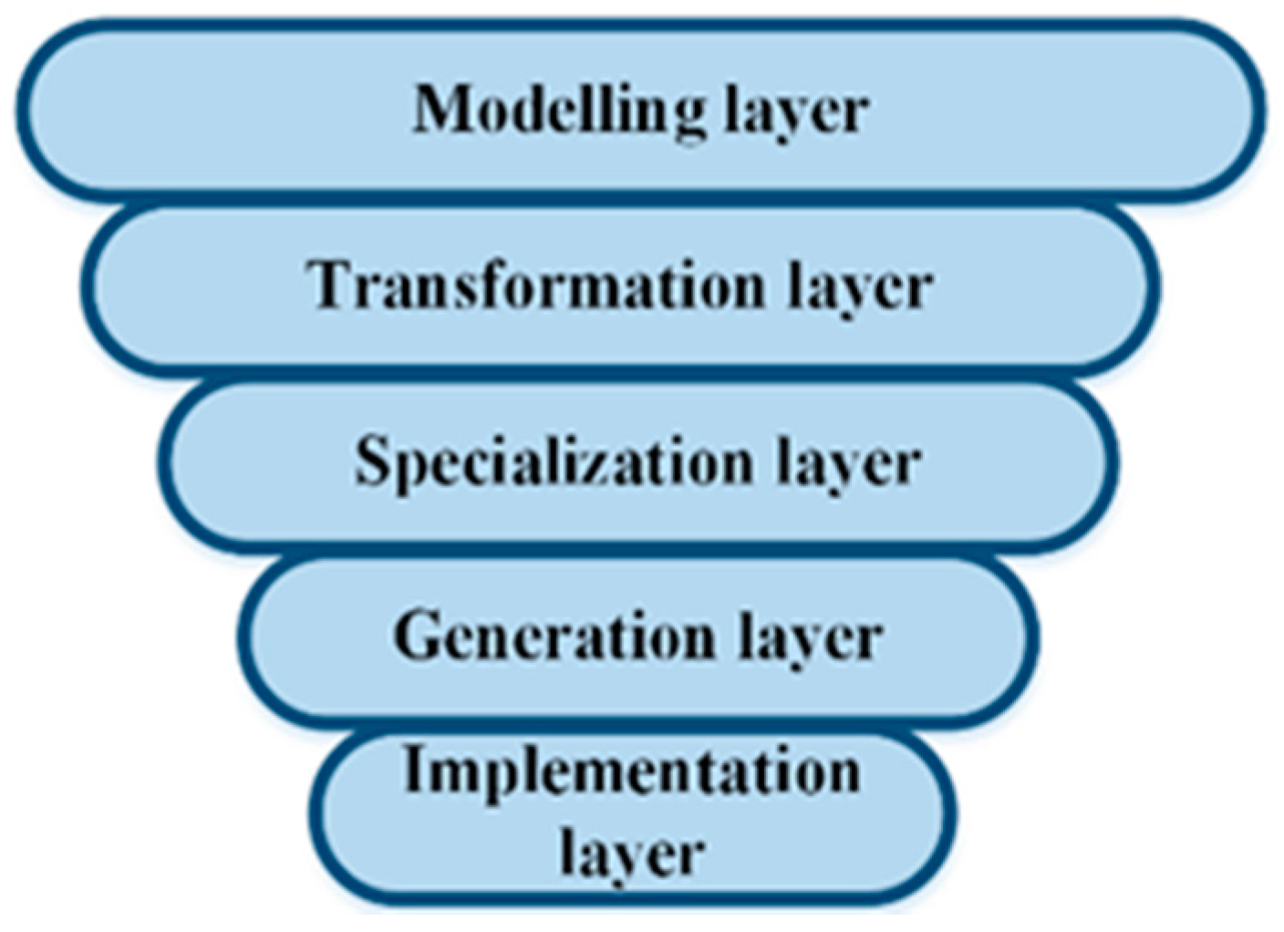
In
Figure 1, we present our framework as a multi-layered stack that includes the modeling layer at the top and the implementation layer at the bottom. Intermediate layers serve for narrowing the design space in order we could be able to apply the model transformations and finally to customize models to achieve the implementation layer. The aim of PHM domain modeling is first to extract the relevant knowledge and then to represent it adequately in order to apply the knowledge in the subsequent layers as easily and effectively as possible. Typically, the resulting knowledge is a set of models of the domain under consideration. The modeling procedure, to be systematic and most useful, requires the use of a well-defined approach. When new designs with reuse in mind are considered (e.g., PLE approaches), typically feature-based modeling is applied [
32,
33]. We do the same for analyzing the upper layer of our framework.
Firstly, in
Section 3.1, we present a background along with basic definitions to understand the introduced framework. Secondly, in
Section 3.2, we describe the process-based implementation of the proposed framework.
3.1. A Background of the Methodology
As our methodology at the top level of the computational framework uses the feature notion, we need to define the relevant basic terms. As the notion is independent on the application, the definitions we provide below are common for many other systems too (not only for PHM).
Definition 1. The feature is a distinguishing characteristic of a domain (e.g., system, component, process, PHM), which is considered important by the stakeholder in the given context of use (for other definitions, see [
33]).
A feature is treated:
- (i)
as the mandatory feature that is always selected if its parent feature is selected;
- (ii)
as the optional feature that can be selected or not;
- (iii)
as the alternative feature(s) that are grouped, and the selection from the group is governed by logical relations OR and XOR.
Definition 2. A feature model (further FM, also feature diagram) is a set of the following components:
- (i)
root tree: G = (F, r, E), where F is the finite set of features, r—root feature (r ∈ F); E is a finite set of the edges E ⊆ F × F;
- (ii)
set Emand is the set of edges that define the mandatory features with their parents P(Emand ⊆ E);
- (iii)
the graph Gxor ⊆ P(E) × F defines the alternative feature groups;
- (iv)
the graph Gor ⊆ P(E) × F defines the optional feature groups (here P(E)—child features together with their common parent (P) feature);
- (v)
RQ defines the finite set of constraints Requires;
- (vi)
EX defines the finite set of constraints
Excludes (Definition 2 adapted from [
32]).
Definition 3. Feature models hold the following properties:
- (i)
FM is said to be aggregated if it is created through combining two or more input FMs into one output model using the pre-specified aggregating rules integrated within the adequate tools.
- (ii)
FM is said to be specialized if it is derived from its ancestor FM through removing some features (if a parent feature is removed, all of the children’s features are removed as well).
- (iii)
FM is said to be abstract if some features have no atomic features with concrete values, or, in the other context, some features may be decomposed into parts.
- (iv)
FM is said to be concrete if atomic features have concrete values.
- (v)
FM configuration is the model that contains all mandatory nodes of the given FM, may contain optional nodes and includes variation points, but only one variant for each variation point is selected.
Transformation rules are the basis to implement the model transformation. There are two types of FM transformation: (1)
model-to-model (M2M)
transformation that defines the correspondence between elements of the input and output feature models; (2)
model-to-program (M2P). The first covers the transformation and specialization layers while the second covers the generation and implementation layers. The transformation rules are to be supported by the adequate tools (they will be introduced in
Section 3.2).
Definition 4. Model-driven computational framework is the structure to enable the FM transformations and software code generation governed by predefined requirements and capabilities of the adequate tools.
3.2. Description of the Methodology
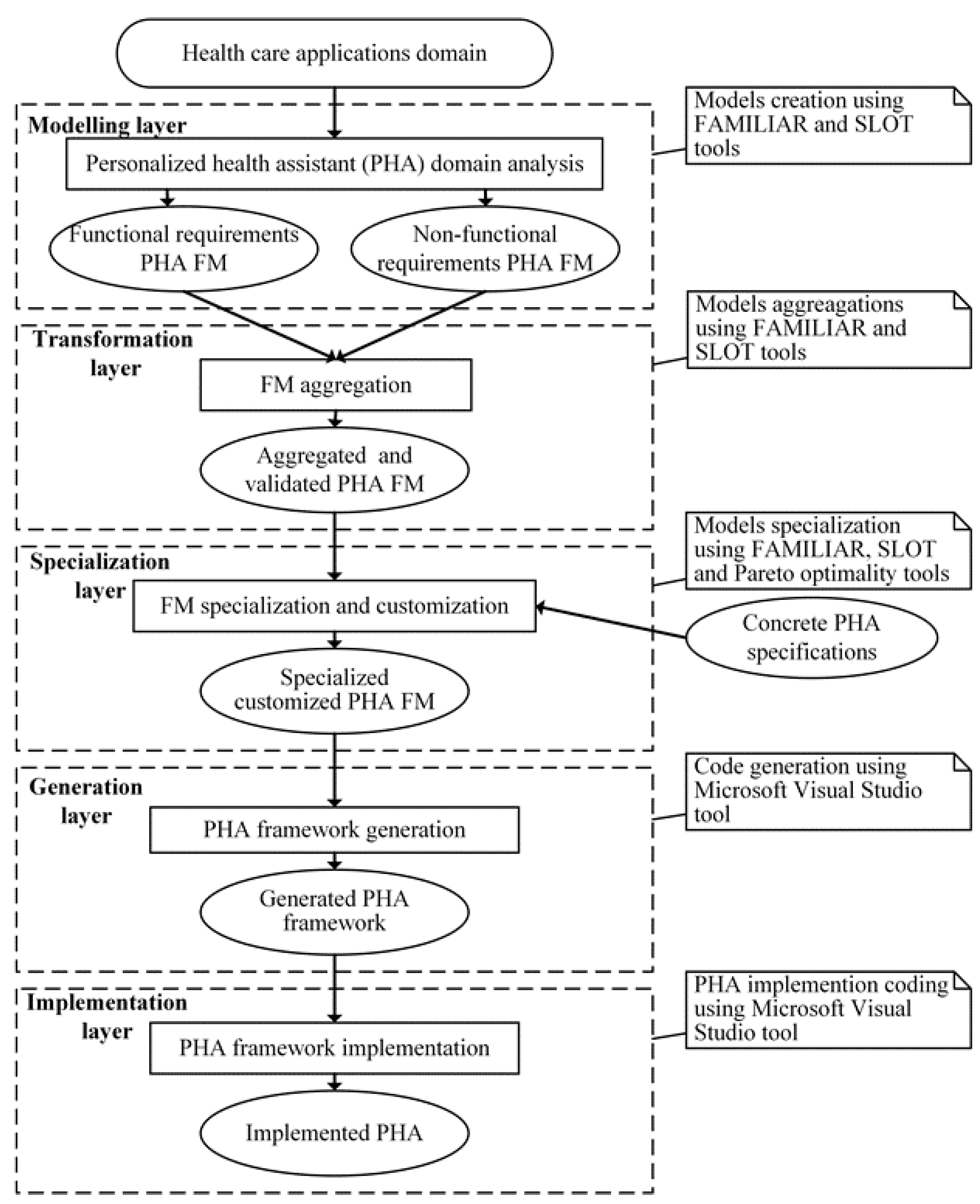
In
Figure 2, we present the overall design processes to implement the framework. Each layer represents the adequate process along with the input-output models and tools used to support the process. As a result of modeling the different aspects of requirements are considered separately (due to their complexity), i.e., a set of separate feature models (further input models) is created.
The transformation layer (process) serves for aggregating the input models into the resulting model. The main intention is to ensure the reuse potential in using the model-driven paradigm. The conditions of aggregating are as follows: the input models are consistent, being represented uniformly using the feature-based notion, and general enough (meaning the adequate scope of domain expressed by features) to support the pre-defined extent of reuse. Aggregation might be carried out not for all input models but for the selected models. For example, the most likely aggregation could be composed of the resulting model from the non-functional models (i.e., security and energy related models). The aggregated model for reuse should be the abstract model. Consistency should be verified. Therefore, the verification process is a part of both the modeling and transformation processes to be supported by adequate tools (FAMILIAR [
34] for modeling and aggregation and SPLOT [
35] for verification).
The models created so far are too general, meaning that they are oriented to a variety of possible applications that cover a huge space of possible functional and non-functional requirements. In other words, they support a high extent of reuse. Therefore, before reusing they must be adapted to the concrete context of use. The abstract models should be specialized. Model specialization is a kind of transformation that aims at to achieve two goals: (1) to add the concrete values to some abstract features; (2) to narrow the search space by introducing specific requirements related to the concrete situation of use. Therefore, those layers (transformation-specialization) are about the model-to-model (M2M) transformation that does not change the abstraction level.
As M2M transformation rules are based on properties (see Definition 3,
Section 3.1) and are hidden within tools FAMILIAR and SPLOT, we do not present more details on the rules here. Instead, we focus on the next generation layer that is also about transformations. Here, the aim is to produce the program code through model-to-program (M2P) transformations. This kind of transformation results in lowering the level of abstraction. As there is a difference in representing the feature models and the program to be created, it is difficult to perform the straightforward transformation. Therefore, we implement the process through a series of lower-level transformations. The M2P transformation rules are given below.
Tools indicated in
Figure 2 are used to perform M2M transformations. M2P transformations (i.e., FM to class diagrams of the object oriented programming language (OOPL)) are performed using the Microsoft Visual Studio tool applying the following rules:
- (a)
A high-level feature of the input FM corresponds to OOPL elements, such as Class, Class specification, or Enumeration;
- (b)
A sub-feature of the input FM corresponds to the same elements plus Interface of the OOPL;
- (c)
The constraint Requires of the FM corresponds to the OOPL element Aggregation;
- (d)
The constraint Excludes of the FM corresponds to the OOPL element Composition;
- (e)
The mandatory feature of the FM corresponds to the OOPL class diagram association (1);
- (f)
The optional feature of the FM corresponds to the OOPL class diagram association (0..1);
- (g)
The alternative feature(s) that are grouped and the selection from the group is governed by logical relations (OR decomposition) corresponds to the OOPL class diagram association (1..*);
- (h)
The alternative feature(s) that are grouped and the selection from the group is governed by logical relations (XOR decomposition) corresponds to the OOPL class diagram association (1..1).
Finally, the implementation layer (see again
Figure 1) is concerned with the introduction of the hardware part (i.e., sensors, data concentrator, communicating and transferring facilities) according to the predefined reference architecture (
Figure 3). Then, by embedding the program components created in the generation layer into the architecture, it is possible to make the prototype system function within the predefined scope, requirements, and functionality.
4. A Case Study: Implementation of the Computational Framework
In this section, we describe a case study to show the implementation of the proposed framework. To do so, firstly we consider the architectural aspects by introducing a prototype of the IoT-related PHM applications. Then we describe results obtained for each layer in detail.
4.1. The IoT-Based PHM Application Prototype
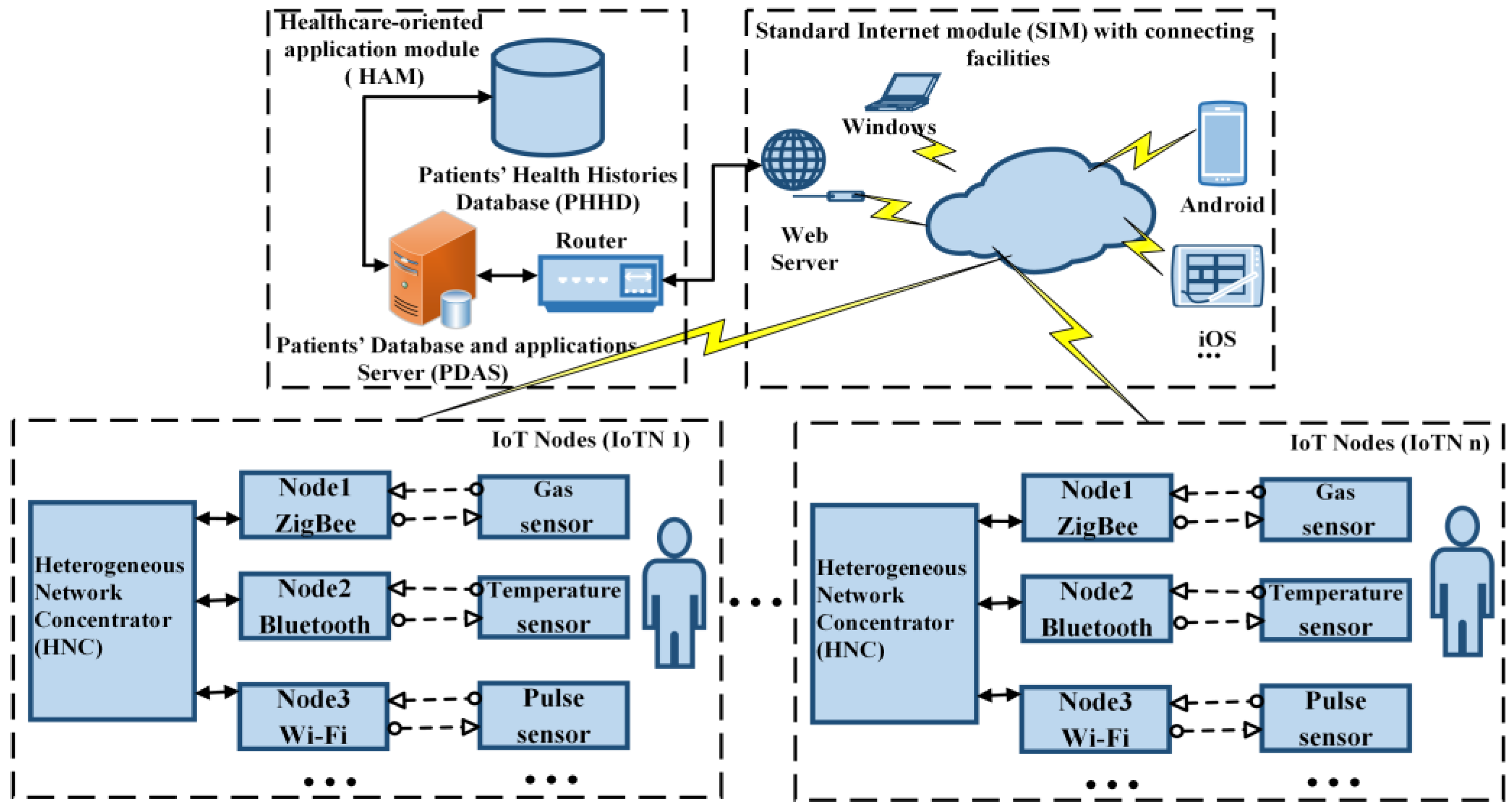
In
Figure 3, we present the
three-level reference architecture of the prototype as a result of healthcare domain analysis. Its
highest level contains PHM application module (HAM) with adequate facilities (e.g., patients’ health histories database (PHHD), patients’ database and application server (PDAS)). The standard Internet module (SIM) with connecting facilities represents the
intermediate level. The distributed wireless sensors network (DWSN)
represents the lowest level. The latter is identified as the IoT Node or IoTN for short. In fact, it represents a sub-net of the DWSN along with additional facilities. In terms of our application, it is treated as a PHM or another medical-related system. As we focus on data collection, communication, and functional aspects here, the module IoTN represents the core of the reference architecture. The module is responsible for providing the initial data. In healthcare applications, there is a need to collect a huge number of data from different parts of the patient’s body. In case of the prototype, however, it is more important to focus on two aspects: (1) typical measurements (e.g., measuring the patient’s temperature, blood pressure, pulse, gases) and (2) different functionality of the sensors used for measuring. As the body parameters of each patient may be specific, we need to have sensors for different functionalities. Therefore, we assume that there are (i)
simple sensors that are able to transfer the measured data only (say, measurement of gases); (ii)
functional sensors with the restricted functionality (say, measurement of temperature); and (iii)
multi-functional sensors to provide various calculations before transferring data (say, measurement of pulse).
Typically, the measured data are private and are not to be allowed to be captured and misused. The security protocols ensure that; however, the security level may be different for various applications or for the specific cases of the same application as it is in our case (e.g., for different patients). Therefore, PHM applications are concerned with choosing the adequate protocol from the set of available ones. As it is highlighted in the structure of IoTN, different sensors may require different protocols. Typically, multi-functional sensors require more advanced protocols (e.g., Wi-Fi, see Node3 in
Figure 3). Therefore, the sensor’s type predefines the use of the adequate protocol. The collected data from different sensors are to be combined and presented as a common structure before being transferred to the HAM. The sub-module, identified as the heterogeneous network concentrator (HNC) within the component IoTN (see
Figure 3) fills this role. As the modules IoTN and HAM are typically located in remote places, the sub-module HNC also ensures the interfacing facilities with SIM.
The procedure of obtaining initial data and then transferring them according to the selected protocol is also concerned with energy consumption. The latter highly depends on the mode of using IoTN (e.g., intensiveness of the data stream, sensor type, protocol to be used, and state of the environment). For telemedicine applications, energy issues are important too, because there are many battery-charged medical devices in use. All these factors in building the PHM application should be taken into account at the initial phase when the requirements for the application are to be stated. Therefore, the requirements fall into two categories: non-functional (related to energy and security, environmental factor) and functional (related to the measured data and their transferring). Note that the medical interpretation and the use of the data is not the concern of the prototype. Even in this simplified example, there are many variants of the factors to be considered and evaluated. However, the real IoT applications are far more complex. In fact, they are systems of systems with a huge variability space of interacting factors.
4.2. Implementation of Transformation Layers
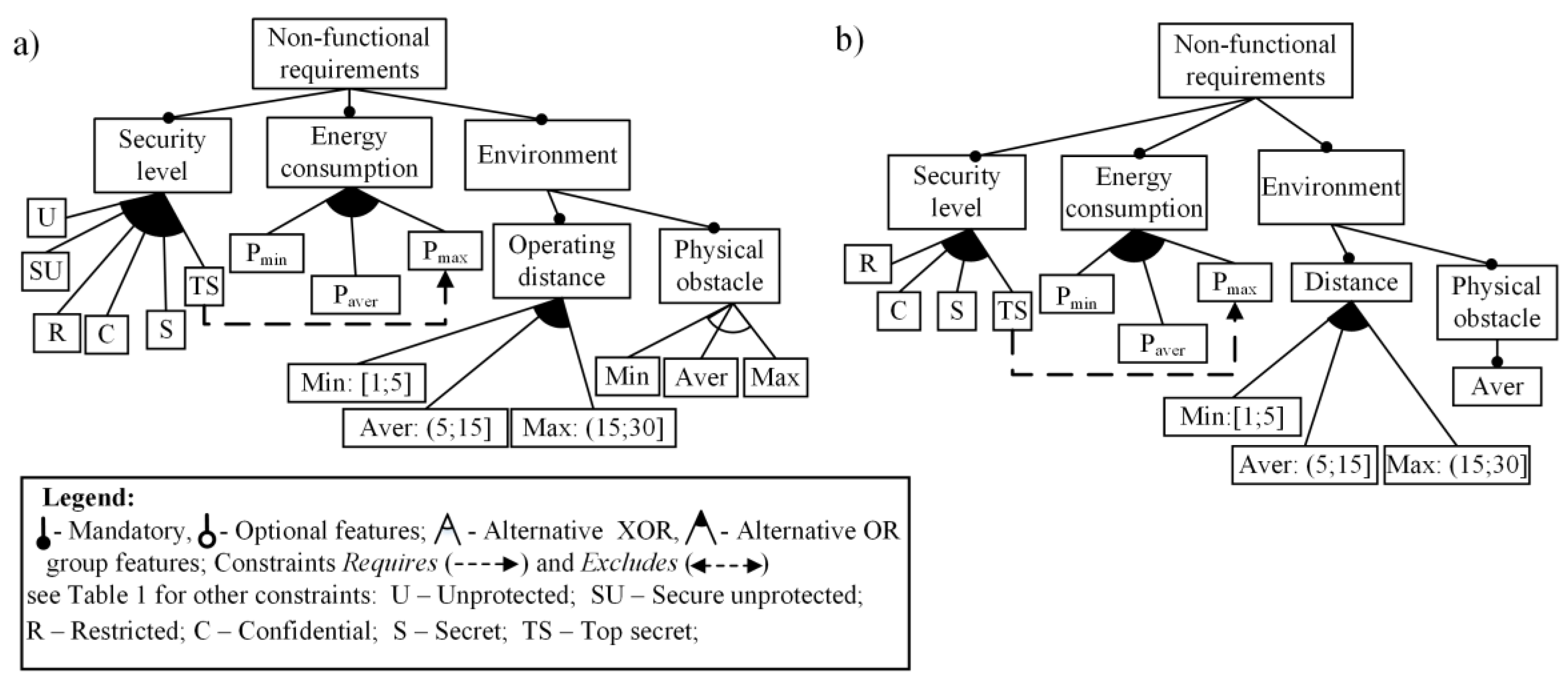
In
Figure 4, we present the feature model (FM) that specifies
a set of the non-functional requirements with the focus on the security, energy, and environmental aspects as related to the component IoTN. Those aspects are considered as mandatory features (see
Section 3.1, for this and other definitions). All the features are decomposed to achieve the level of atomic features (variants). The variation points and variants specify variability (
Figure 4, e.g.,
Security level, Physical obstacle, etc.); therefore, the requirements cover the set of the possible alternatives in representing requirements for different systems. The variants can be also treated as
fuzzy variables because of the lack of preciseness. The values of the variables are to be selected using either expert knowledge or previous knowledge of the designer. For example, values of the security level were taken from [
31]; the others were estimated on the basis of the experimental results given in [
18]. Here, physical obstacle values (Min, Max, Aver) mean the environmental factor influencing to signal transferring (noise) in rural regions, city regions, and between adequately.
In fact,
Figure 4 presents two models: initial (
Figure 4a) and specialized (
Figure 4b). In terms of the introduced definitions (
Section 3.1), both are concrete models. The specialized model is derived from the first. Further, we analyze the specialized model aiming at simplifying the task. We have also omitted some other constraints for simplicity. The specialized model should be correct. The model has been created and verified using the tools FAMILIAR [
34] (for modeling) and SPLOT (for verification) [
35].
Similarly, using the expert knowledge and adequate tools, we are able to construct
the correct model to represent functional requirements of our prototype. We omit the visualization of this model here. As both requirements (non-functional and functional) in the same project are to be considered together, we need to create
the aggregated model that includes both FMs. Therefore, in
Figure 5, we outline the aggregated FM of both functional and non-functional requirements. Here, as compared with the architecture (
Figure 3), sensors are defined as concrete functional units (pulse, temperature, and gas sensors). Each sensor, as the parent feature, consists of other features to define the functionality of the sensor (operating range, distance, protocol, and accuracy).
The remaining part of the functionality is represented by the feature “Communication” with its own sub-features. This feature model (
Figure 5) is also a concrete specialized model (again constraints of the type
Requires and
Excludes are missed). It is reasonable to present constraints separately due to the readability and understandability issues. It is created using the same tools that support these types of transformations.
In
Table 1, we present the constraint relationships within the aggregated model. The result of the modeling and verification processes (they also include aggregation) is the construction of the correct feature models. They are represented in two formats: graphical and textual. The latter is being specified in SXML (should be interpreted as simple XML).
The verification tool SPLOT also yields a set of characteristics of the aggregated FMs along with results of debugging analysis (see
Table 2; in fact, there is a reduced number of the characteristics). As the initial aggregated model specifies a set of possible alternatives predefined by the anticipated requirements, the variability space (it is evaluated by count configurations, see
Table 2) may be too large to implement the created model. Therefore, we provide the specialization of the initial aggregated model in order to narrow the solution space.
The essential characteristics of the verified model (there are no dead features) are the constraints, the count of features, and their types, the configuration count. The latter defines the reuse scope (the number of the family members) for further analysis and implementation.
4.3. Implementation of the Code Generation Layer
For this layer, input data is obtained for the specialized feature model. In fact, the configuration count predefines the set (see
Table 2, line “Count Configurations”, Column 3). The specialized model has eight configurations. At this level, all or some configurations might be taken into account because we apply the ‘product line’ approach. Having several variants, it is possible to make a comparison and investigation to define the one that fits best in a given situation. However, as we have selected Microsoft Visual Studio tools that require also manual code writing, we need to customize specialized FM configurations to only one configuration (see the selected fragment (b) in
Figure 5 obtained from FM (a)) for implementing the code generation. Note that the selected FM fragment contains mandatory features that are linked with the sensors nodes through constraints (see
Table 1). The configuration has been selected taking into account the Pareto optimal solution [
30].
There are different tools with slightly different capabilities to support the approach. The main requirements in selecting the tools are (1) support of feature-based models and (2) type of the target language to develop the system. As the software designer’s choice was the target OOPL C#, we have used Microsoft Visual Studio tools. The other choice, for example, for programmers in Java may use Eclipse tools and environment. The tool Visual Studio accepts OOPL class diagrams as input and produces C# code templates as output. Therefore, generation is run as the two-stage transformation process: (1) FM – OOPL class diagram; (2) OOPL class diagram—C# code. Here, OOPL class diagrams stands for the tool’s input language to specify intermediate models. The templates of the C# code stand for the output model. Therefore, the overall functionality of the tools is specified by the set transformation rules we discussed in
Section 3.2.
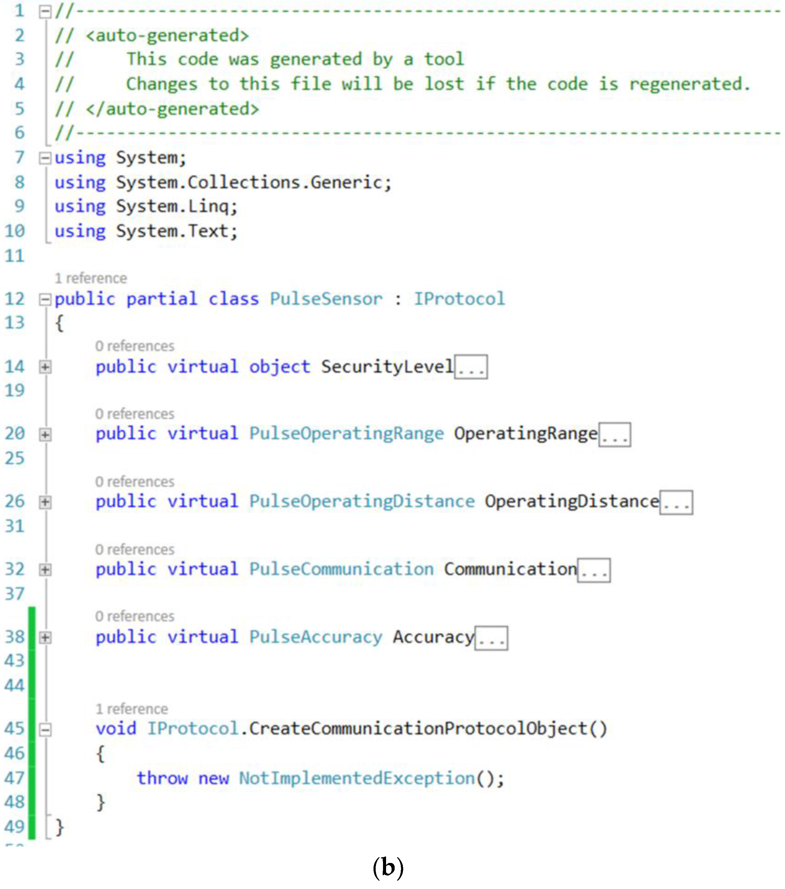
In
Figure 6, we present the OOPL class diagram fragment (a) and the generated C# code (b). Here, the class diagram PulseSensor corresponds to the FM fragment “Pulse sensor” (see
Figure 5). In
Table 3, we summarize the overall results (i.e., the main characteristics of the transformation process) gained at the generation phase. It is important to highlight some characteristics of the process. For example, the automatically generated code covers the eight possible configurations (products in terms of product line). A great deal of code either does not require human intervention at all, or the manually written code is minimal. However, the physical implementation of the concrete sensor functionality requires a substantial number of lines of code (LOC) to be written manually (see the three last lines in
Table 3) for the customized concrete configuration. However, in this regard, one should take into account the fact that the designer has a template telling him/her where the code should be placed and what code must be created. The latter is the significant enforcement of the design productivity.
4.4. Implementation in Hardware and Experiments
The solution of the generation layer is the C# code template that represents the overall software architecture. It covers all eight selected configurations of the prototype (see
Table 3). In other words, using this prototype software, we are able to create the eight possible software components (for the three nodes of the IoT) for different applications. However, to do that, we first need to fulfill the template-based software using manually written code for concrete customized application (see
Table 3, column on right), meaning also the use of concrete hardware (i.e., sensors). We have selected adequate sensors and, on the basis of the reference architecture (
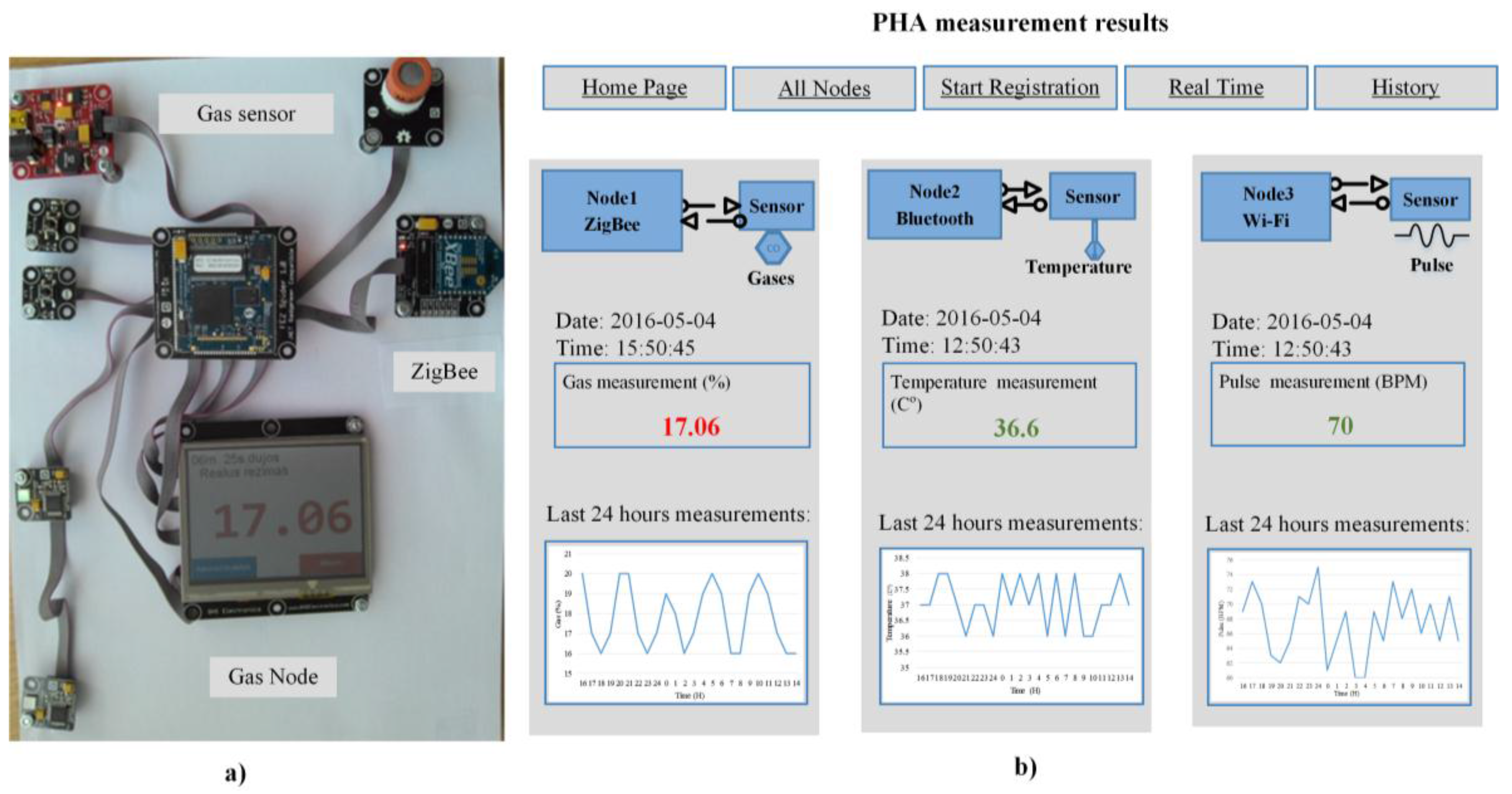
Figure 3) and produced software, created the experimental system for testing and experimentation. Three types of measurements (temperature, gas, and pulse) have been provided at the patient’s side in a few sessions, each lasting about two hours. During the sessions, the measured data were continuously transferred to the remote (doctor’s) side over the Internet. In fact, in our experiments, that side was the other room, where the stream of measurements was monitored on a PC via the Internet. The experiment enabled us to conclude the following issues: (a) all three standard data-transfer protocols were working correctly (meaning the requirements fulfillment, i.e., software produced through the computational framework was correct); (b) the data transfer sessions allowed for evaluation, analysis, and decision-making; (c) monitoring changes and creating histories of transferring the data in real time (
Figure 7). As the selected sensors were not for the medical use, some deviations from the norm of the measured values were observed (e.g., for temperature, see
Figure 7b). Furthermore, we were able to monitor the significant changes of signal values only for the pulse signal, as it is depicted in
Figure 7. If the designer wants to implement the IoT nodes for another application, he/she needs to start not from the beginning but from the generation layer by fulfilling generated templates with specific, manually specified code for the other configuration.
5. Summary, Discussion and Evaluation
In this paper, we have discussed the approach for developing the IoT-based PHM applications. We have sought two goals: (1) to cover the design cycle as much as possible (from requirements to code and from code to its testing on adequate hardware) and (2) to perform the process as effectively as possible (meaning automation). First, we developed an adequate computational framework. Within the framework, development activity was interpreted as a stack of multiple processes subdivided into layers. The known model-driven vision has been applied using feature models to analyze the prototype. Within the vision, we focused on two major activities. The first is concerned with creating the feature models and their transformations (identified as model-to-model (M2M) transformations) on the basis of the pre-defined functional and non-functional requirements of the prototype. The second is concerned with model-to-program (M2P) transformations. The transformations are supported by adequate tools. For the first activity (i.e., modeling, model verification, model transformation), we used the available FAMILIAR and SPLOT tools. For the second activity, we used the Microsoft Visual Studio programming environment.
In general, the feature models enable to capture the essential attributes of the systems to be modeled and to express them through the features and their relationships in the development cycle as early as possible. As systems (such as the IoT) are indeed very complex, the feature models fit well to represent the initial requirements of the domain under consideration. Features are abstract entities, and therefore, using the feature-based notation, it is possible to represent the domain attributes at the different level of abstraction and to model the domain variability explicitly. Here, by domain we mean a possible set of systems within the IoT applications. As it has been shown, even in the case of the simplified version of the introduced prototype, we had 8 different configurations, each represented as a feature model for further analysis and implementation.
Therefore, we are able—already at the early design stages (requirements modeling)—to analyze the system at the highest level of abstraction, to understand its core functionality features, to introduce changes into its functionality, and to model changes not from the scratch but systematically with reuse and automation in mind. It is possible to reason about the bottlenecks of the system to be designed and to exclude them with much less effort and resources. Furthermore, we are able to collect a set of approved artifacts (models are syntactically correct for the explicit variability management) for future applications. That is so because the models are the value per se. They can be used in multiple cases (as the tested knowledge units for experimentation, decision making, etc.). As the feature models also have the textual representation in some language (in our case SXML), it makes the lower-level transformations possible. Next, we are able to achieve a high reuse extent through automation using the available transformation and generation tools. The feature models enable us to represent requirements uniformly, despite their quite different nature (energy, security, environmental factors).
The top-level of our approach, i.e., feature-based modeling, model transformation and specialization, is independent upon the hardware and software platforms; however, generation and implementation layers are platform-dependent. To implement the IoT applications in particular platforms, one can reuse the existing software components. Therefore, the IoT nodes can be created using a variety of sensors and actuators. If one prefers to use standardized sensors, it would be possible to reuse the ready-to-use software components, such as sensor's control programs.
As a result of the provided research, we have also identified some limitations of the approach. First, for the seamless integration of M2M-based and M2P-based transformations, the adequate tools should be compatible. That was not the case with the tools we used because the modeling and verification tools are experimental. Therefore, in order to close this incompatibility gap, human interaction was needed (for transforming SXML [the output of SPLOT] into the XML format that is supported by Microsoft Visual Studio). Therefore, the choice of the available tools is an issue. Though the use of more powerful tools can increase the automation level, the methodology we propose does not suffer from the capabilities of the adequate tools. The other issue is that the template-based code, which is created after generation, is to be completed manually. Therefore, the need for manual interactions decreases the level of automation.
These are purely technical limitations. They have restricted, to some extent, the experimental investigation we were able to provide. Even the restricted experiment has enabled us to achieve aims of the research and approve the soundness of our approach.
6. Conclusions and Future Work
Though the proposed framework has been implemented as prototype oriented to the use in PHM applications, it is general enough and can be helpful for developing other medical applications as well. The following attributes ensure that: (a) feature modeling and model transformations are independent upon the applications because the process Microsoft Visual Studio tools support the product line vision, i.e., it ensures a high extent of variability in creating related systems; (b) narrowing the variability space through the model specialization enables to adapt requirements to the needs of the possible use; and (c) the implementation covers the full design cycle, in which the product line concept is preserved until the need to create the concrete software part for the specific application hardware arises.
The framework provides the possibility for a wide-scale experimentation to test and monitor the behavior of the prototype in the real-time mode through an Internet browser so that it is possible to obtain and select the most suitable characteristics for real applications.
The processes and tools introduced and discussed within the framework are seen as a computational framework that aims to support flexibility through reuse and automation. Due to complexity issues, the computational framework does not ensure full automation; though some handwork in designing IoT software is needed, the framework brings a systematic view and helps in writing the needed domain-specific code manually.
The static feature modeling has proven to be an adequate top-level approach in the context of the stated aims and requirements of our framework. However, more strict requirements (especially in terms of energy awareness and possible environmental changes) may require the introduction of dynamic feature modeling approaches. Researching those aspects as well the seamless integration of different models and transformation tools into the unified design stream are left for a future work.


