
THD Reduction of Distribution System Based on ASRFC and HVC Method for SVC under EV Charger Condition for Power Factor Improvement


Abstract
:1. Introduction
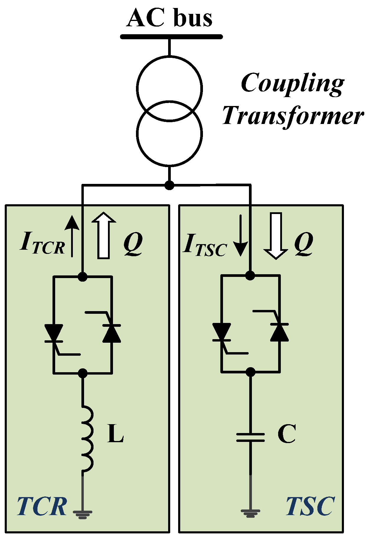
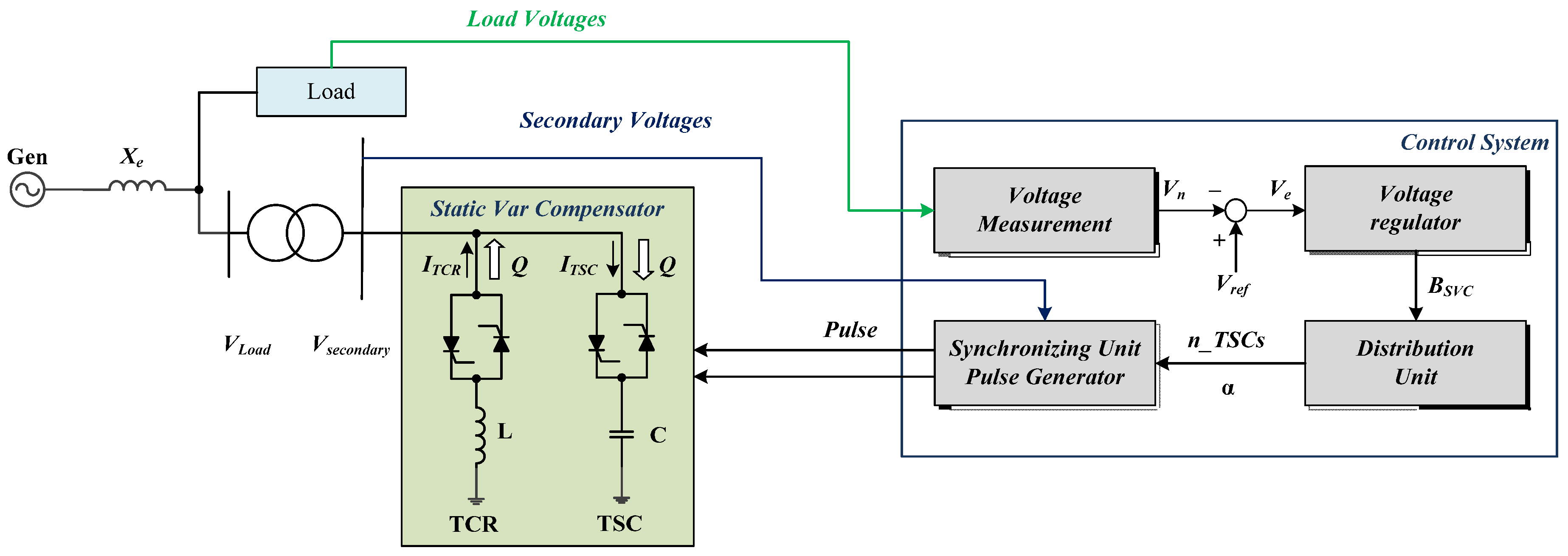
2. Static VAR Compensator (SVC)
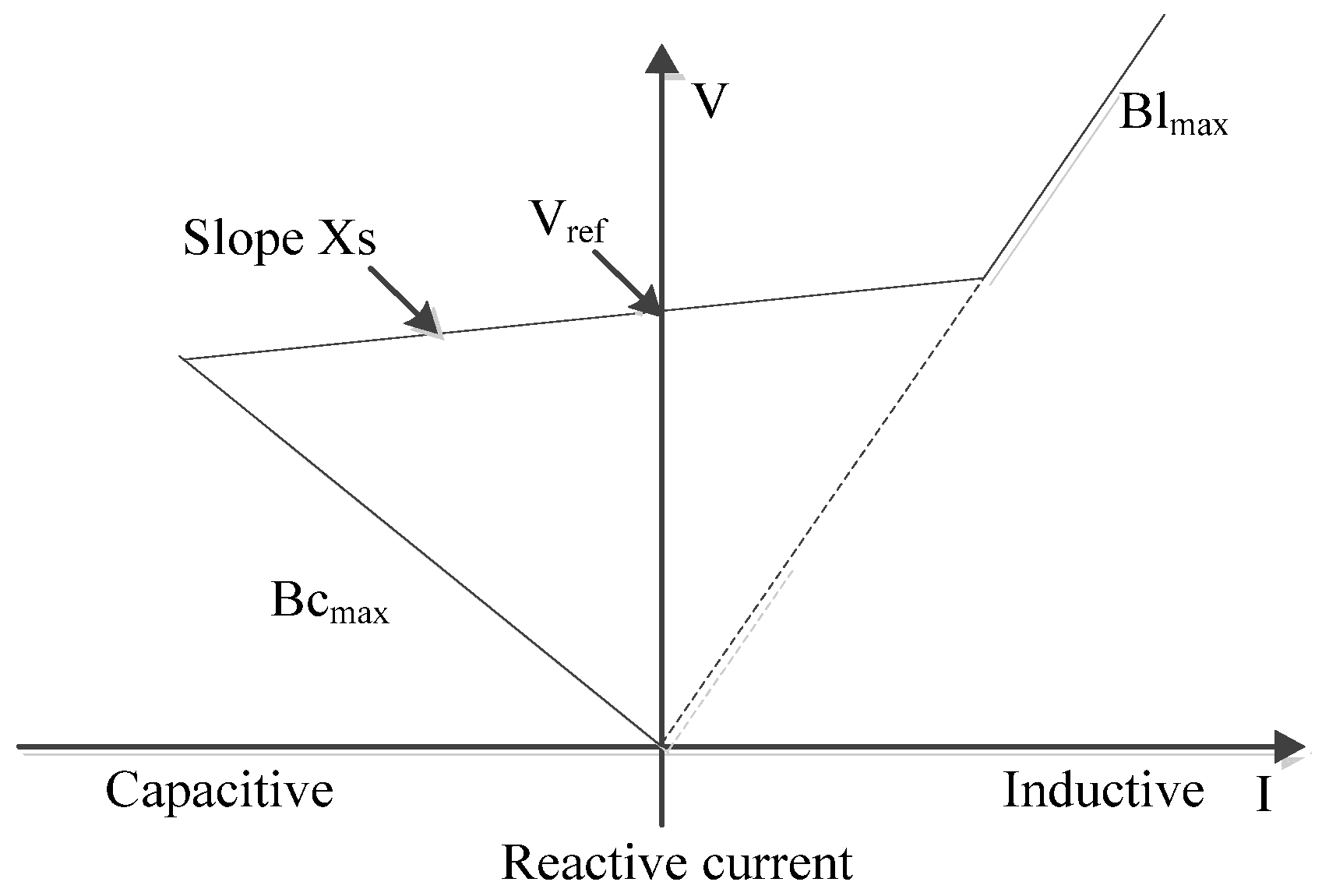
2.1. SVC (V-I) Characteristics
- V: Positive sequence voltage (p.u.)
- I: Reactive current (p.u./Pbase) (I > 0 indicates an inductive current)
- Xs: Slope or droop reactance (p.u./Pbase)
- Bcmax: Maximum capacitive susceptance (p.u./Pbase) with all TSCs in service, no TSR or TCR
- Blmax: Maximum inductive susceptance (p.u./Pbase) with all TSRs in service or TCRs at full conduction, no TSC
- Pbase: Three-phase base power specified in the block dialog box
2.2. SVC Dynamic Response
- Tc: Closed loop time constant
- Ki: Proportional gain of the voltage regulator (p.u._B/p.u._V/s)
- Xs: Slope reactance p.u./Pbase
- Xn: Equivalent power system reactance (p.u./Pbase)
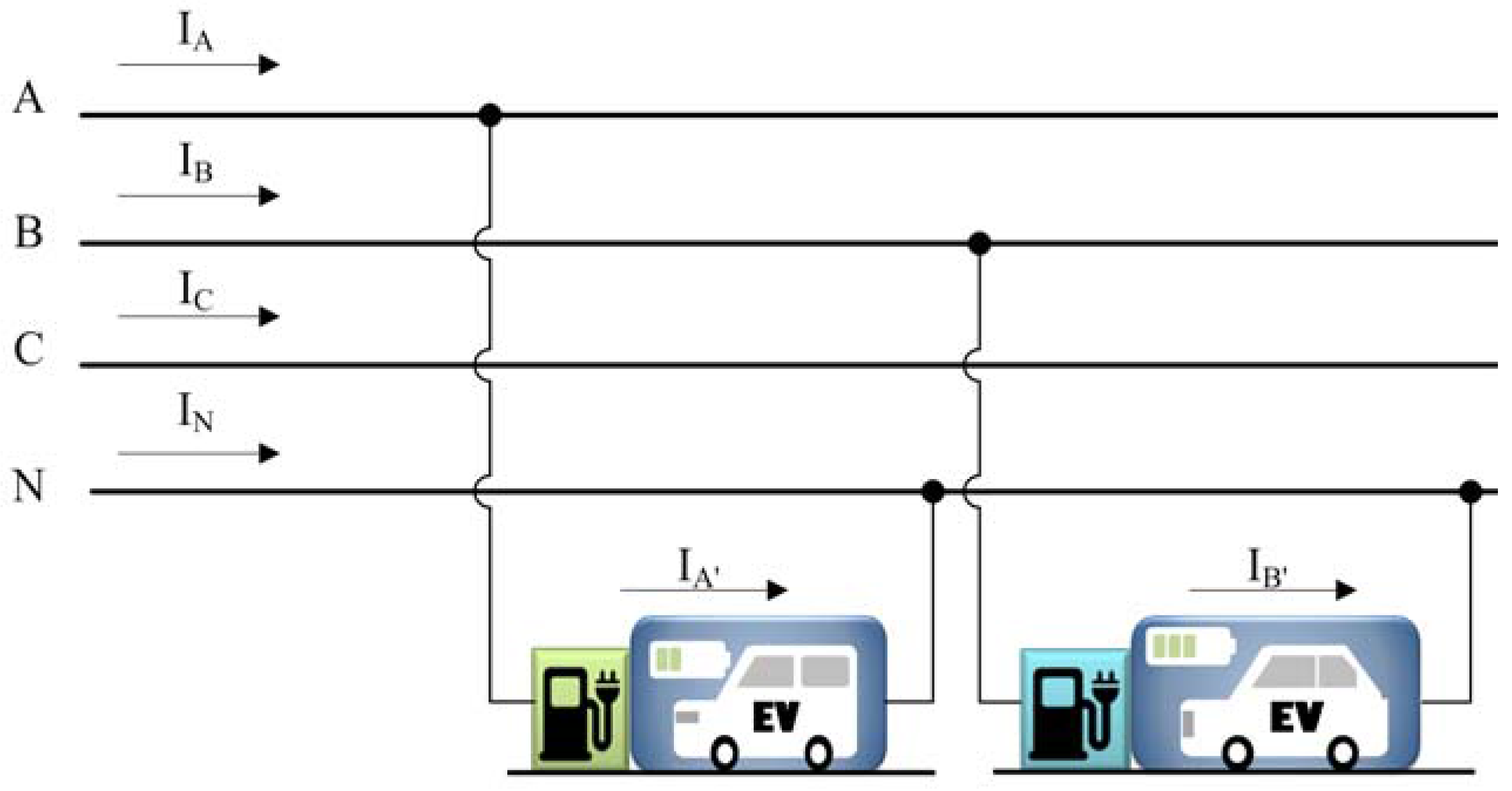
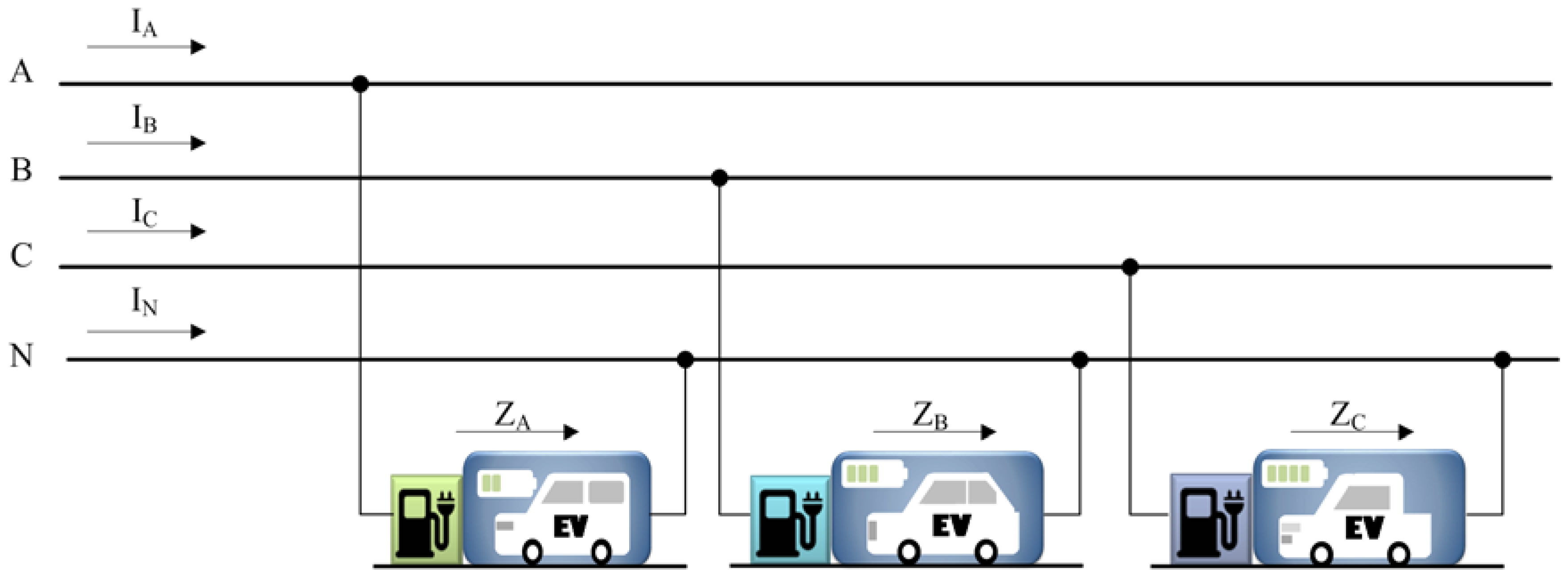
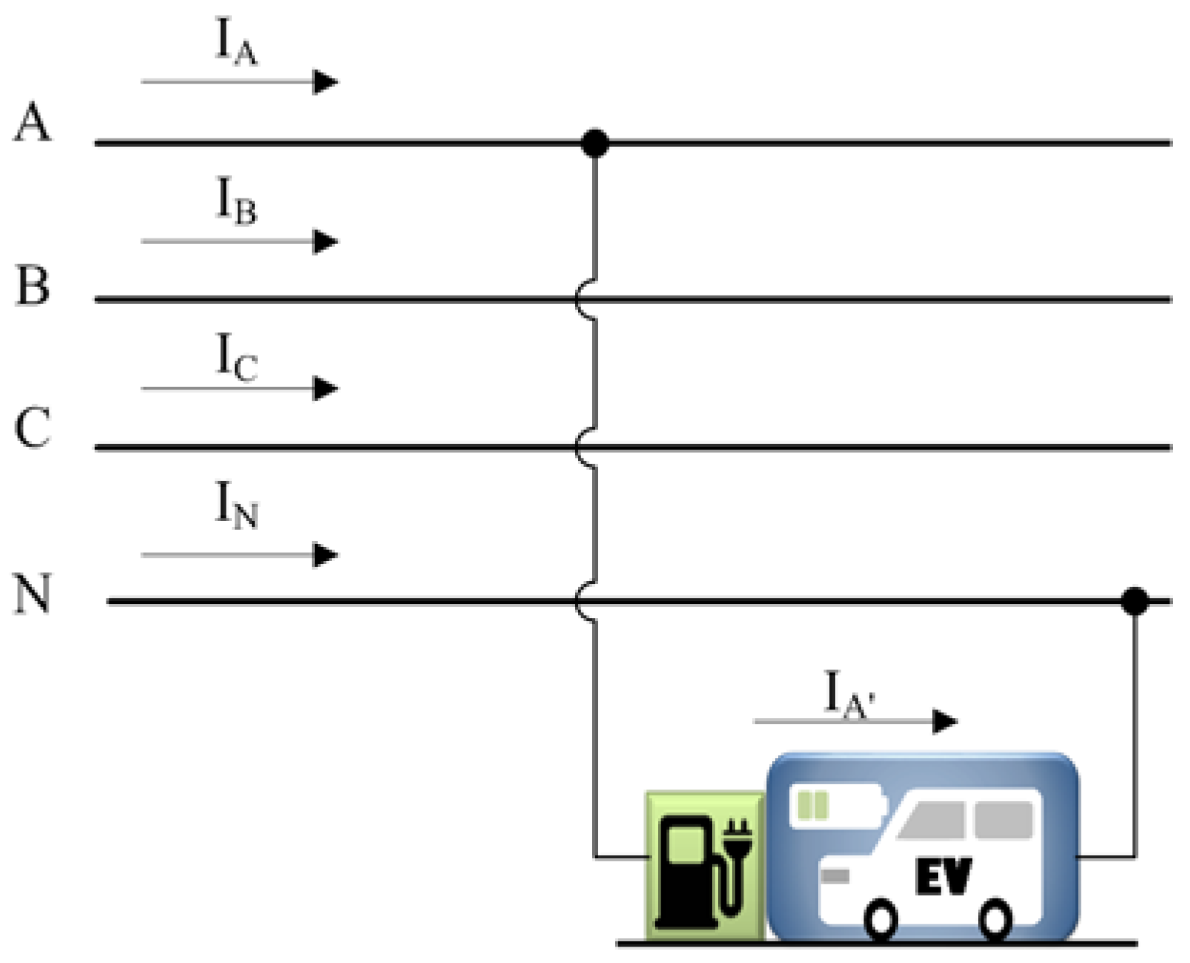
3. Analysis of EVs Connected Phase Voltage
Unbalance Caused by EVs in the Phase Voltage
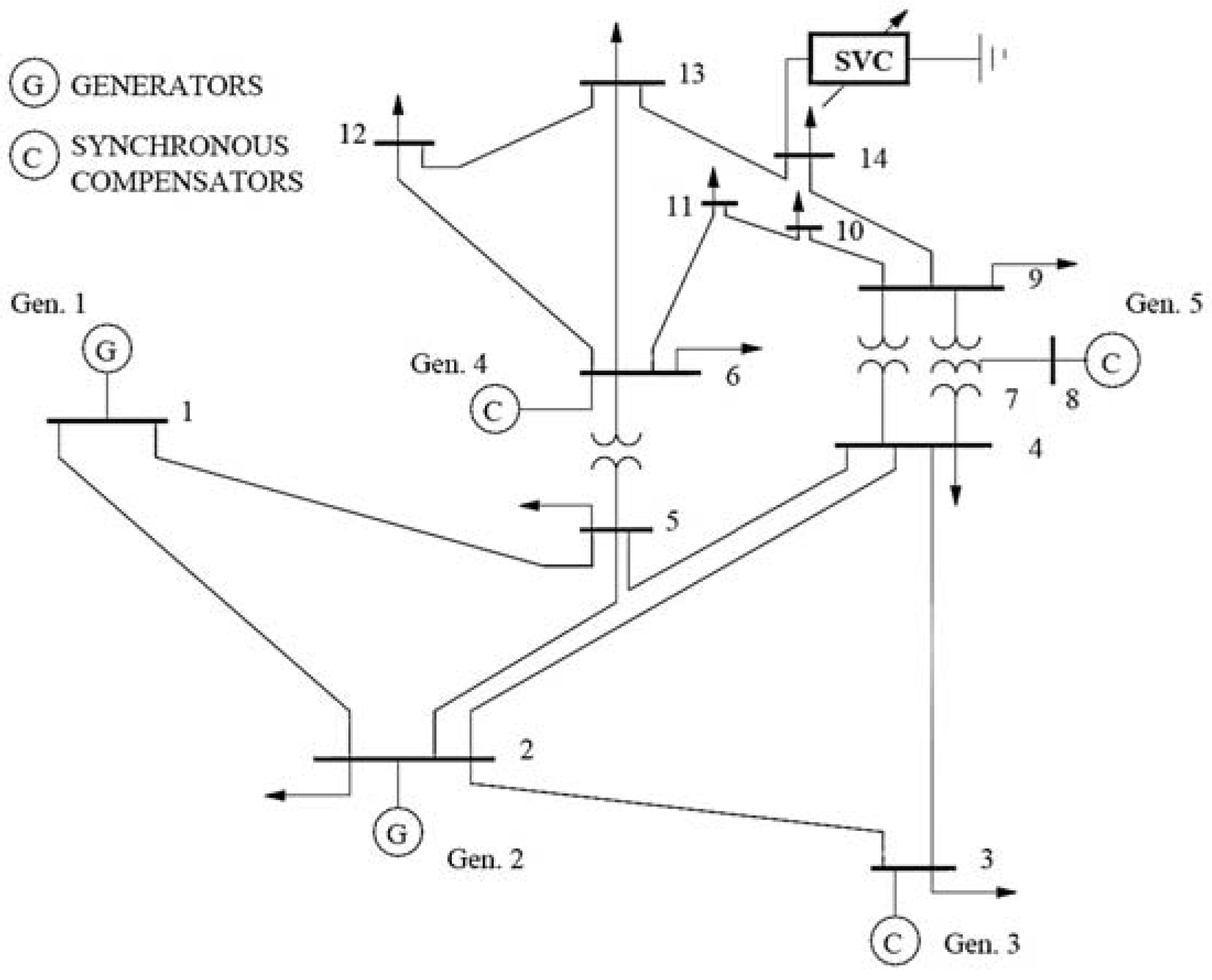
4. Description of System
5. Assumptions and Modeling EV Charging
5.1. Specification of EVs
5.2. Mathematical Models
Stochastic Models
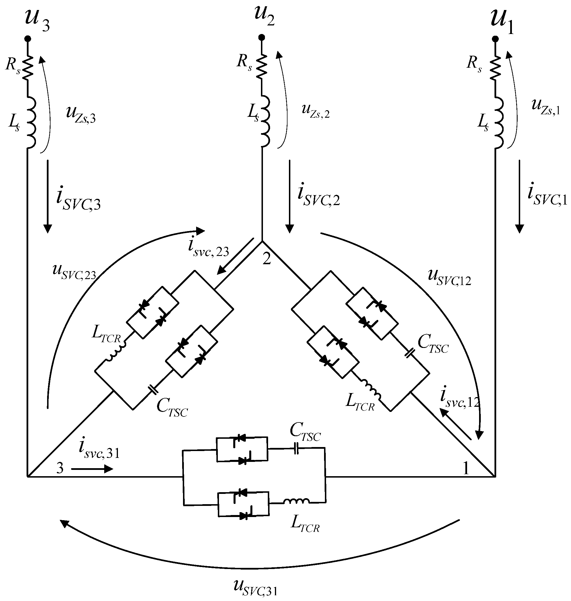
5.3. Modeling of Static VAR Compensator in Power System Studies
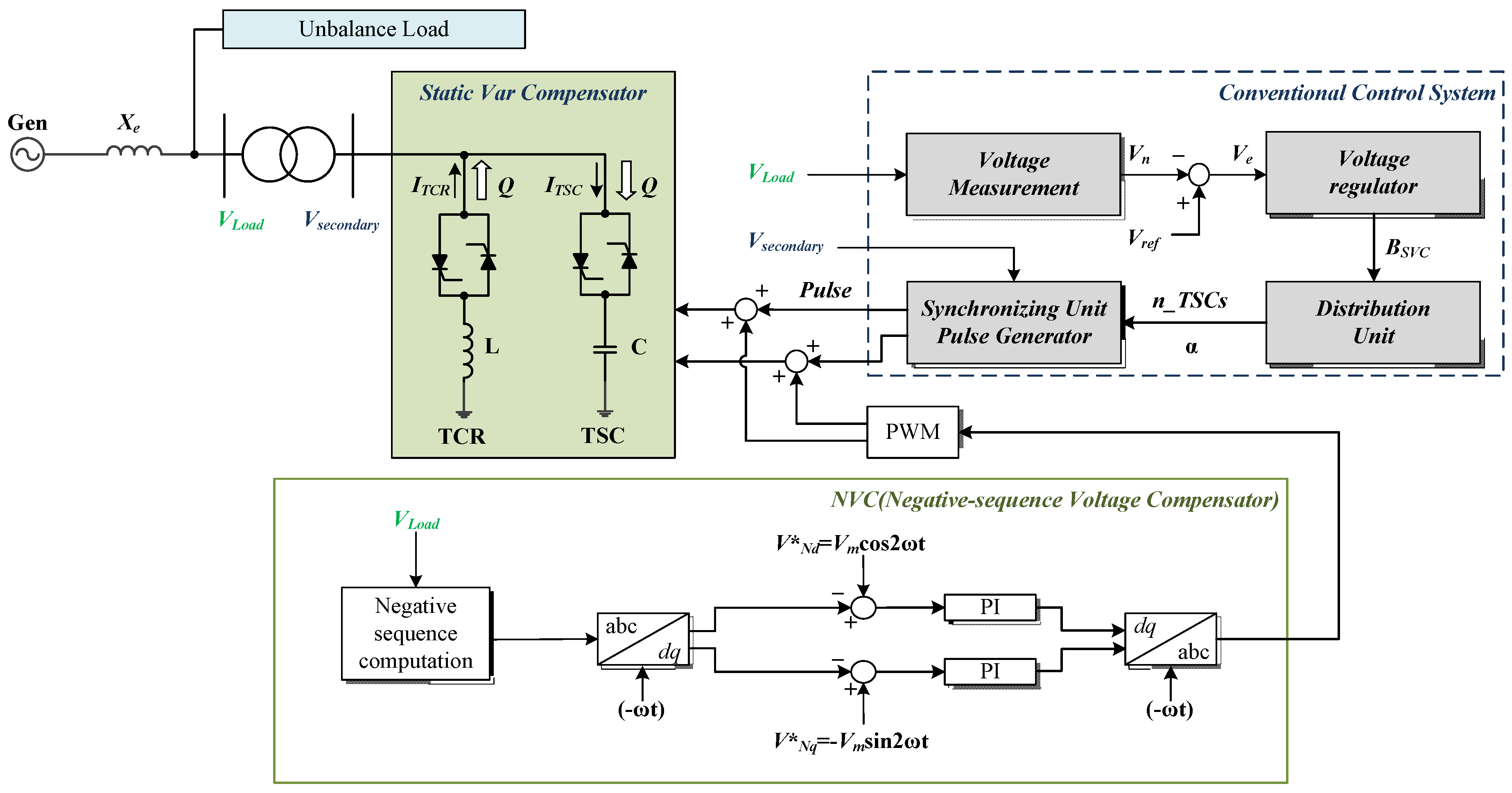
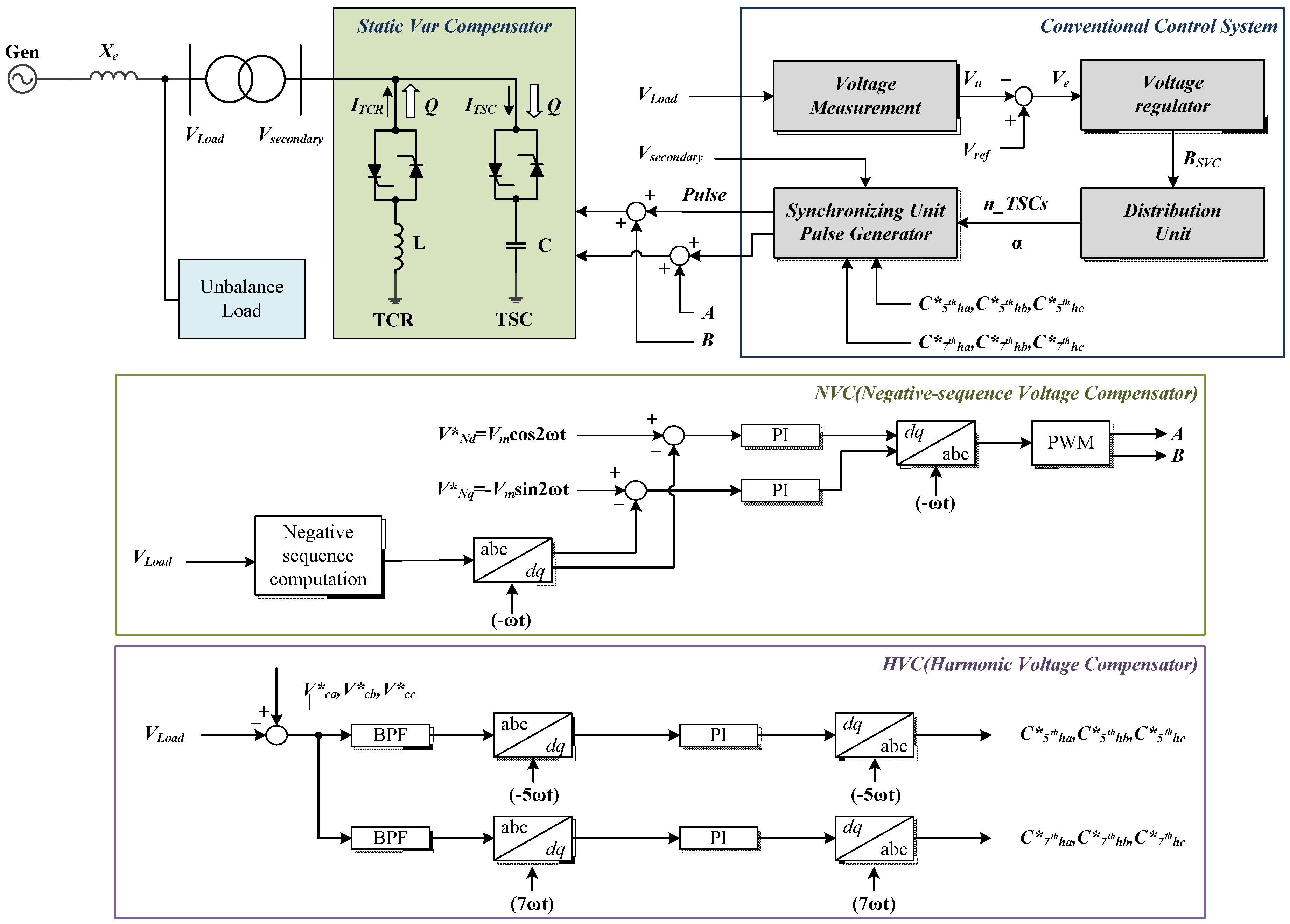
6. Description of ASRFC & HVC in the System
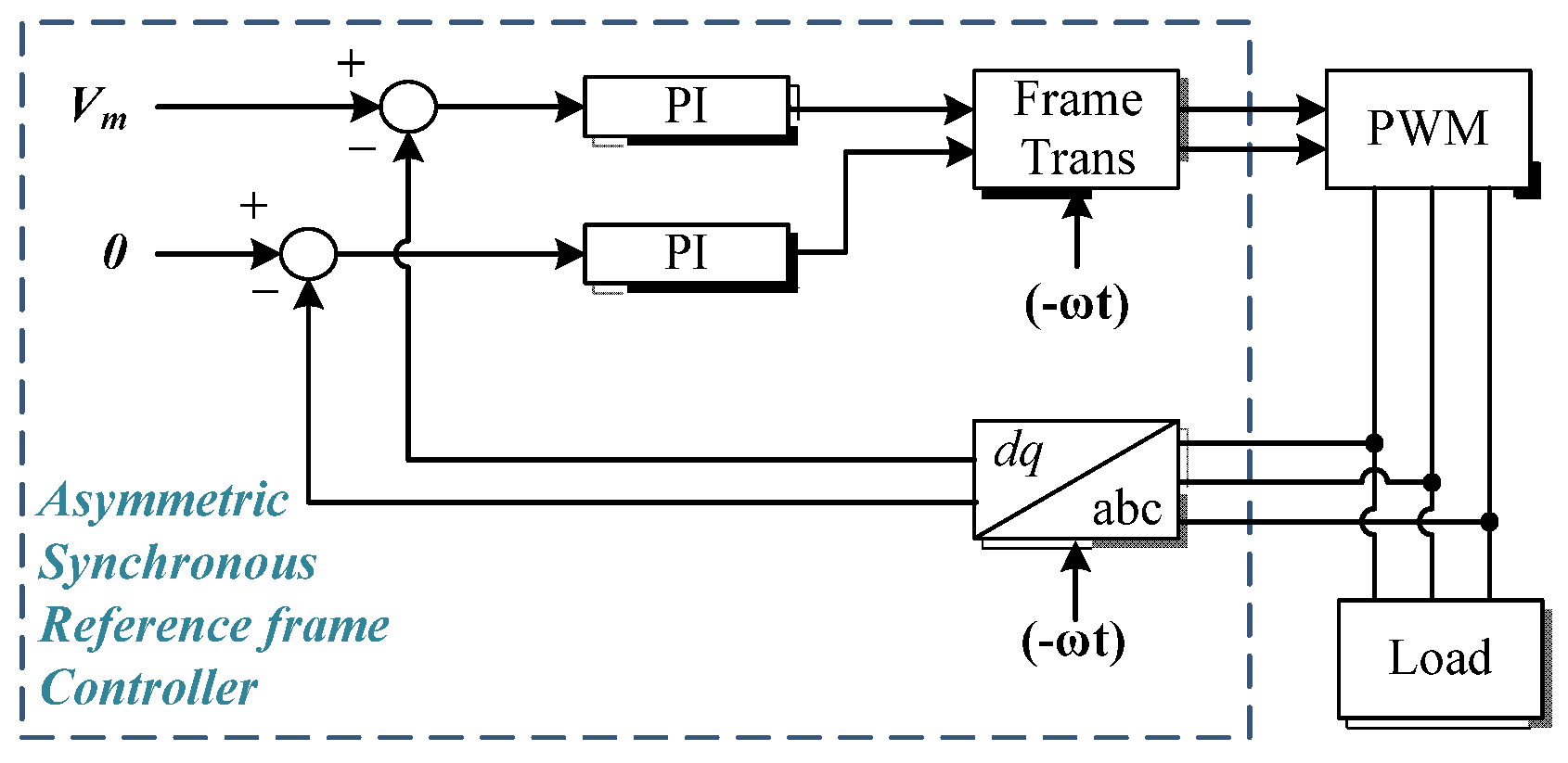
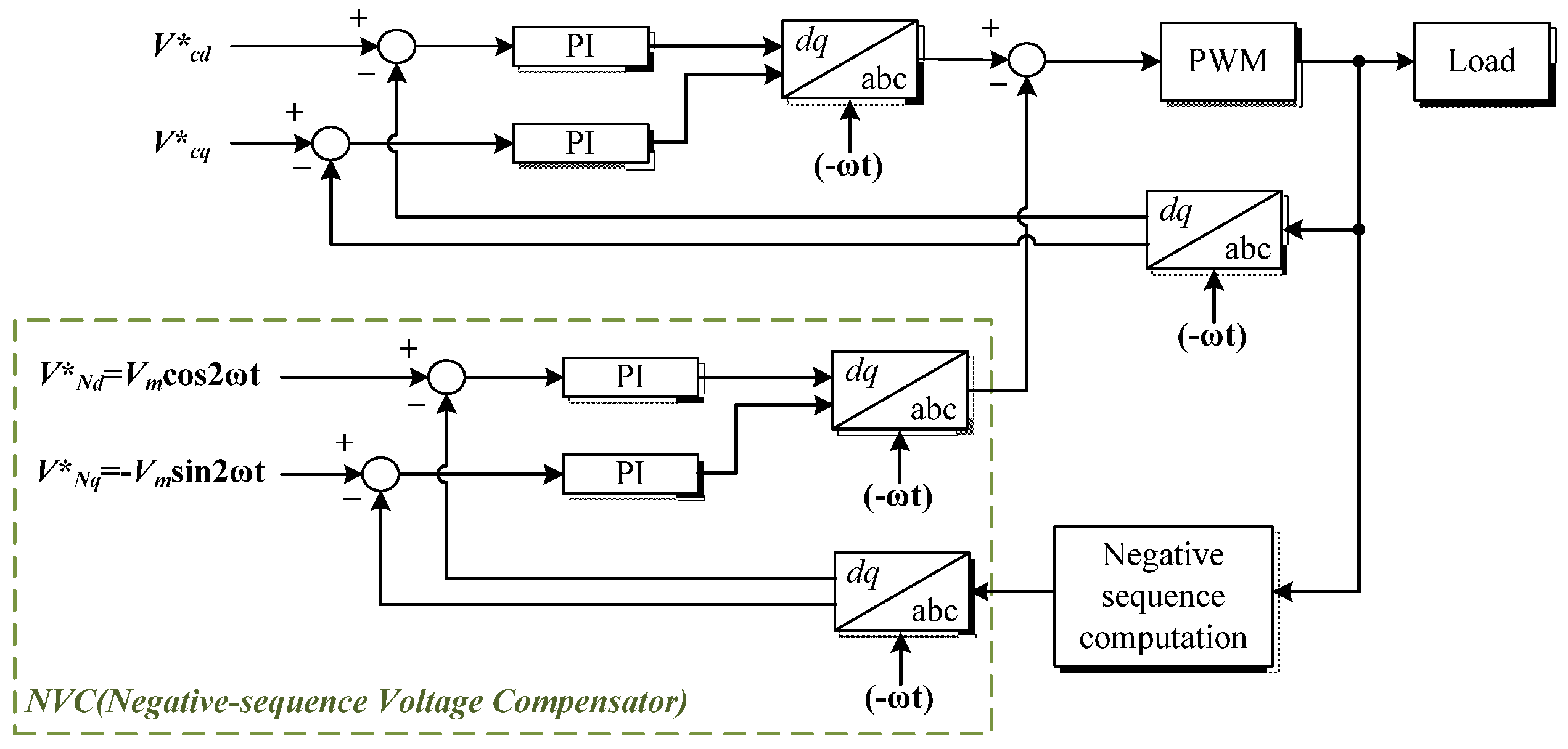
6.1. Asymmetric Synchronous Reference Frame Controller
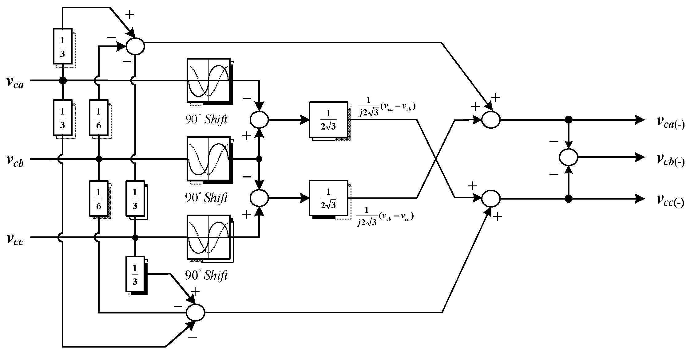
Negative-Sequence Voltage Compensator (NVC)
- vcd is the d-axis voltage in the synchronous reference frame.
- vcq is the q-axis voltage in the synchronous reference frame.
6.2. Asymmetric Synchronous Reference Frame Controller for SVC Connected to the Grid
6.3. Asymmetric Synchronous Reference Frame Control Scheme
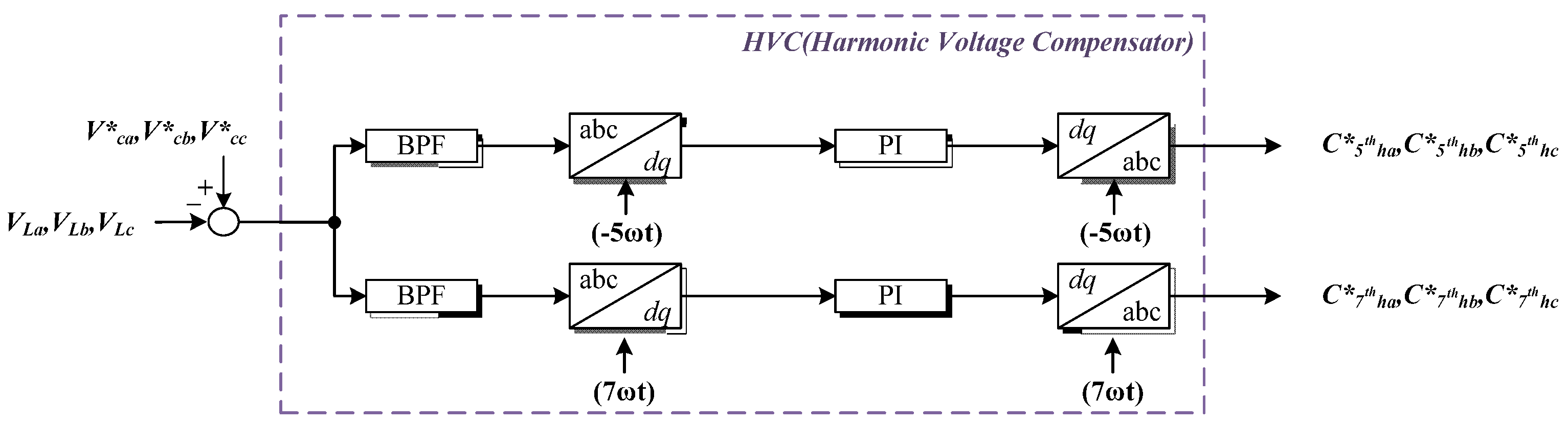
6.4. Harmonic Voltage Compensator
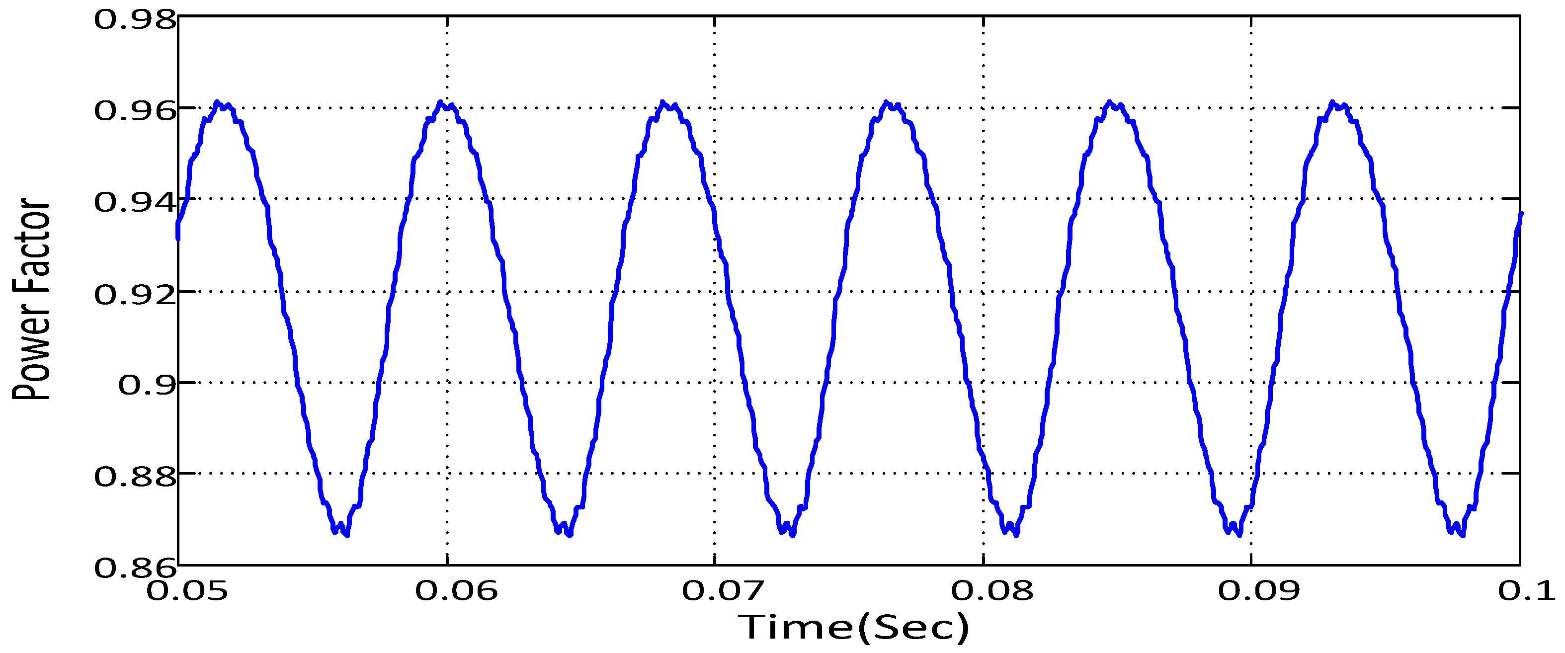
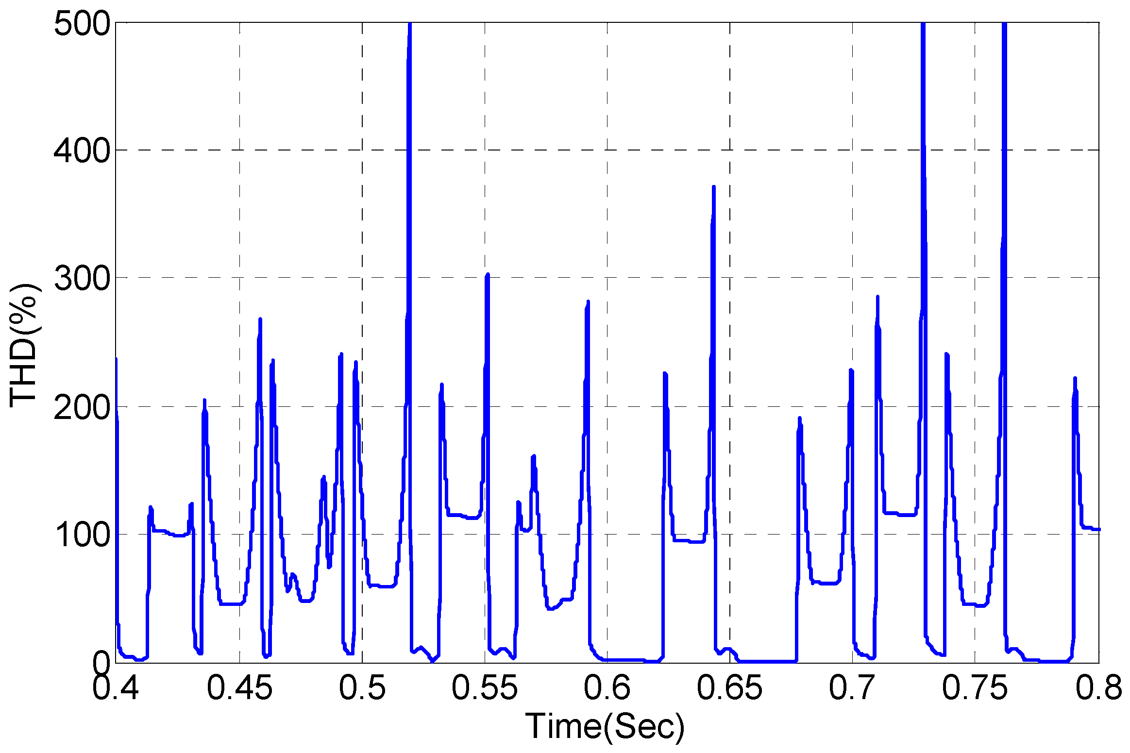
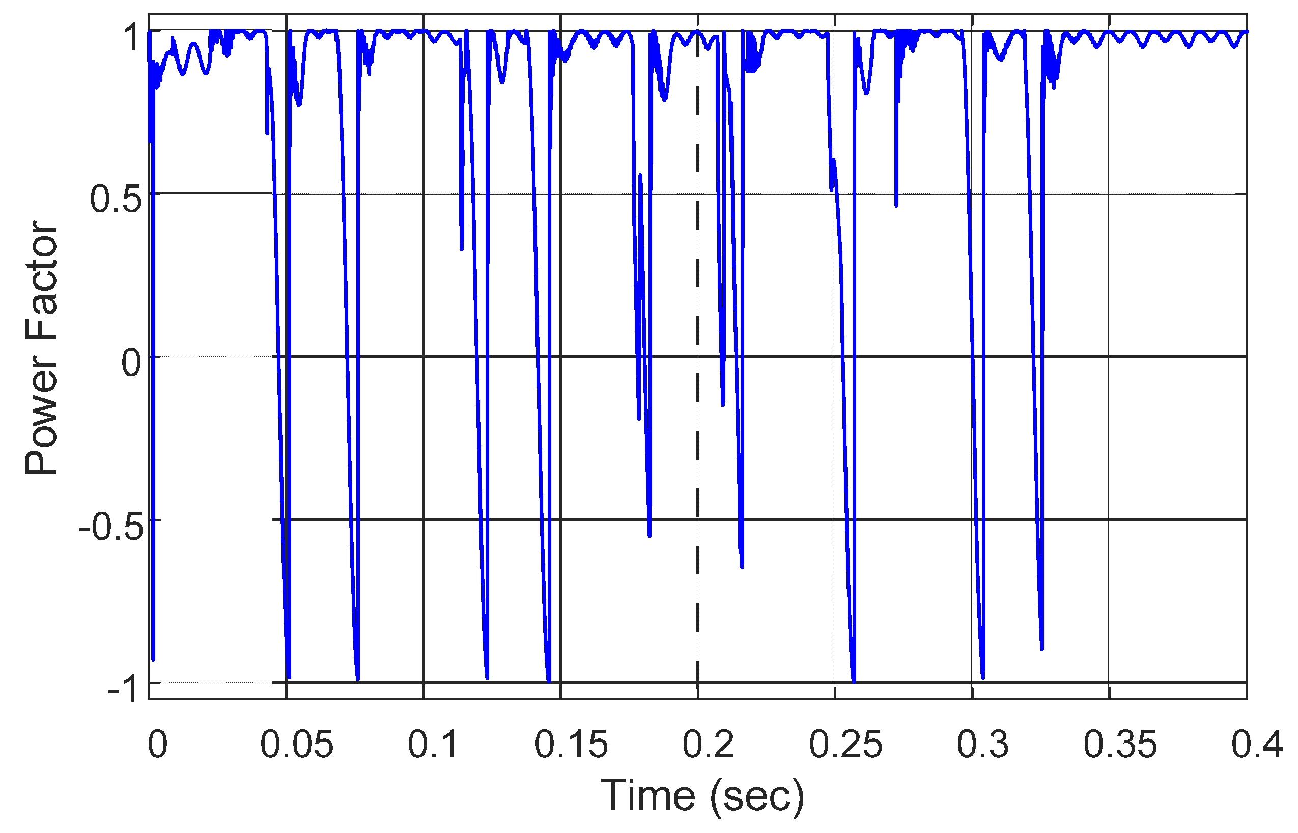
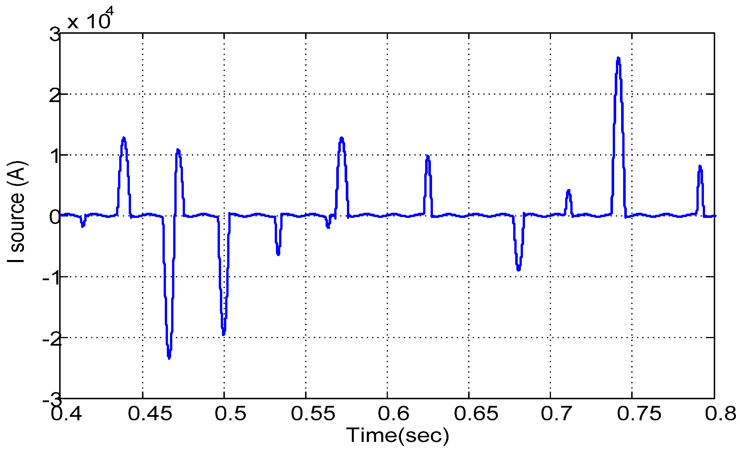
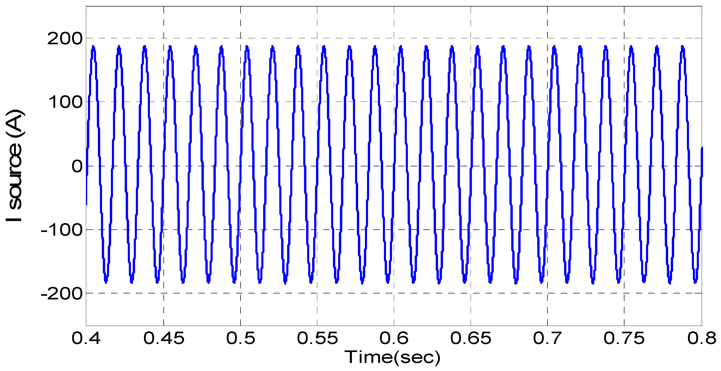
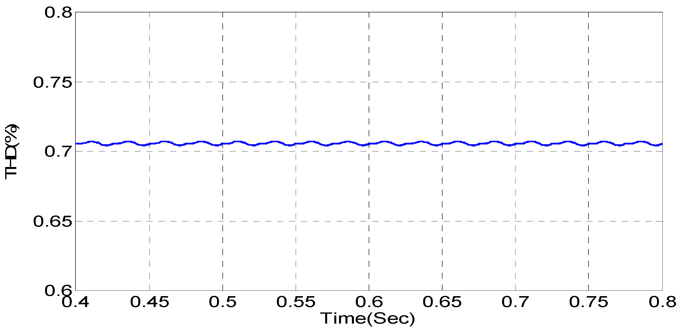
7. Total Harmonic Distortion and Simulation
- f(t): The time domain function.
- n: The harmonic number (only odd values of n are required).
- An: The amplitude of the nth harmonic component.
- T: The length of one cycle in seconds.
8. Conclusions
Acknowledgments
Author Contributions
Conflicts of Interest
References
- Verzijlbergh, R.A.; Grond, M.O.W.; Lukszo, Z.; Slootweg, J.G.; Ilic, M.D. Network impacts and cost savings of controlled EV charging. IEEE Trans. Smart Grid 2012, 3, 1203–1212. [Google Scholar] [CrossRef]
- New York Independent System Operator (NYISO). Alternate Route: Electrifying the Transportation Sector; Technical report; Independent System Operator (ISO): New York, NY, USA, 2009. [Google Scholar]
- Masoum, A.S.; Deilami, S.; Moses, P.S.; Masoum, M.A.S.; Abu-Siada, A. Smart load management of plug-in electric vehicles in distribution and residential networks with charging stations for peak shaving and loss minimization considering voltage regulation. IET Gener. Transm. Distrib 2011, 5, 877–888. [Google Scholar] [CrossRef]
- Gönen, T. Electric Power Distribution System Engineering; Taylor & Francis: Boca Raton, FL, USA, 2007. [Google Scholar]
- Deilami, S.; Masoum, A.S.; Moses, P.S.; Masoum, M.A.S. Real-time coordination of plug-in electric vehicle charging in smart grids to minimize power losses and improve voltage profile. IEEE Trans. Smart Grid 2011, 2, 456–467. [Google Scholar] [CrossRef]
- Shahnia, F.; Ghosh, A.; Ledwich, G.; Zare, F. Voltage unbalance sensitivity analysis of plug-in electric vehicles in distribution networks. In Proceedings of the Australian Universities Power Engineering Conference (AUPEC), Brisbane, Australia, 25–28 September 2011.
- Metke, A.R.; Ekl, R.L. Security technology for smart grid networks. IEEE Trans. Smart Grid 2010, 1, 99–107. [Google Scholar] [CrossRef]
- Moses, P.S.; Deilami, S.; Masoum, A.S.; Masoum, M.A.S. Power quality of smart grids with plug-in electric vehicles considering battery charging profile. In Proceedings of the IEEE Power and Energy Society (PES) Conference on Innovative Smart Grid Technologies Europe, Gothenburg, Sweden, 11–13 October 2010; pp. 1–7.
- Ipakchi, A.; Albuyeh, F. Grid of the future. IEEE Power Energy Mag. 2009, 7, 52–62. [Google Scholar] [CrossRef]
- Green, R.C., II; Wang, L.; Alam, M. The impact of plug-in hybrid electric vehicles on distribution networks: A review and outlook. Renew. Sust. Energy Rev. 2011, 15, 544–553. [Google Scholar] [CrossRef]
- Masand, D.; Jain, S.; Agnihotri, G. Control algorithms for distribution static compensator. In Proceedings of the IEEE International Symposium on Industrial Electronics, Montreal, QC, Canada, 9–13 July 2006; pp. 1830–1834.
- Abdel-Rahman, M.H.; Youssef, F.M.H.; Saber, A.A. New static VAR compensator control strategy and coordination with under-load tap changer. IEEE Trans. Power Deliver. 2006, 21, 1630–1635. [Google Scholar] [CrossRef]
- Rahman, H. Stability improvement of power system by using SVC with PID controller. Int. J. Emerg. Tech. Adv. Eng. 2012, 2, 226–233. [Google Scholar]
- Mokhtari, M.; Golshannavaz, S.; Nazarpour, D.; Farsadi, M. Control of an SVC for the load balancing and power factor correction with a new algorithm based on the power analysis. In Proceedings of the 2010 First Power Quality Conference, Tehran, Iran, 14–15 September 2010.
- Hagh, M.T.; Abapour, M. Fuzzy logic based SVC for reactive power compensation and power factor correction. In Proceedings of the International Power Engineering Conference, Singapore, 3–6 December 2007.
- Ohnishi, T.; Hojo, M.; Matsui, N. Instantaneous line voltage controlled harmonics compensator. In Proceedings of the 26th Annual Conference of the IEEE, Las Vegas, NE, USA, 22–28 October 2000.
- Menniti, D.; Burgio, A. A comparison between an active resonance damper and a harmonic voltage compensator. In Proceedings of the 10th International Conference on Environment and Electrical Engineering (EEEIC), Tehran, Iran, 8–11 May 2011.
- Akagi, H. Control strategy and site selection of shunt active filter for damping of harmonics propagation in power distribution systems. IEEE Trans. Power Deliver. 1997, 12, 354–363. [Google Scholar] [CrossRef] [Green Version]
- Santana, W.C.; Al-Haddad, K.; da Silva, L.E.B. Active resonance dampers: A comparison between fixed and adaptive gains. In Proceedings of the 35th Annual Conference of IEEE Industrial Electronics, Porto, Portugal, 3–5 November 2009.
- Mattavelli, P.; Fasolo, S. Implementation of synchronous frame control for high performance AC power supplies. In Proceedings of the 2000 IEEE Industry Applications Conference, Roma, Italy, 8–12 October 2000; Volume 3, pp. 1988–1995.
- Hsu, P.; Behnke, M. A three-phase synchronous frame controller for unbalanced load. In Proceedings of the 29th Annual IEEE Power Electronics Specialists Conference, Fukuoka, Japan, 17–22 May 1998; Volume 2, pp. 1369–1374.
- Kodsi, S.K.M.; Claudio, C.A. Modeling and Simulation of IEEE 14 Bus System with Facts Controllers; Technical Report; University of Waterloo: Waterloo, ON, Canada, 2003. [Google Scholar]
- Duvall, M.; Knipping, E. Environmental Assessment of Plug-In Hybrid Electric Vehicles. Volume 1: National Wide Greenhouse Gas Emissions; Technical Report; Electric Power Research Institute: Palo alto, CA, USA, 2007. [Google Scholar]
- Denholm, P.; Short, W. An Evaluation of Utility System Impacts and Benefits of Optimally Dispatched Plug-In Hybrid Electric Vehicles; NREL/TP-620-40293; National Renewable Energy Laboratory: Golden, CO, USA, 2006. [Google Scholar]
- Clement-Nyns, K.; Haesen, E. The impact of charging plug-in hybrid electric vehicles on a residential distribution grid. IEEE Trans. Power Syst. 2010, 25, 371–380. [Google Scholar] [CrossRef] [Green Version]
- Grahn, P. Electric Vehicle Charging Modeling. Ph.D. Thesis, Royal Institute of Technology, Stockholm, Sweden, 2014. [Google Scholar]
- Park, R.H. Two reaction theory of synchronous machines. Generalized method of analysis—Part I. Trans. Am. Inst. Electr. Eng. 1929, 48, 716–730. [Google Scholar] [CrossRef]
- Pokorny, M. Analysis of unbalance due to asymmetrical loads. Iran. J. Electr. Comput. Eng. 2005, 4, 50–56. [Google Scholar]
- Reyes, M.; Rodriguez, P.; Vazquez, S.; Teodorescu, R.; Carrasco, J.M. Enhanced decoupled double synchronous reference frame current controller for unbalanced grid-voltage conditions. IEEE Trans. Power Electr. 2012, 27, 3934–3943. [Google Scholar] [CrossRef]
- Somkun, S.; Chunkag, V. Unified unbalanced synchronous reference frame current control for single-phase grid-connected voltage-source converters. IEEE Trans. Indust. Electr. 2016, 63, 5425–5436. [Google Scholar] [CrossRef]
- Liberado, E.V.; Pomilio, J.A.; Marafão, F.P. Harmonic analysis of static VAR compensator operating under distorted voltages. In Proceedings of the 17th IEEE Power & Energy Society (PES) International Conference on Harmonic and Quality of Power (ICHQP), Belo Horizonte, Minas Gerais State, Brazil, 16–19 October 2016.


| Variable Names | Meaning |
|---|---|
| KPI | Proportional and integral gain constant |
| ϴ | ωt |
| INdcmd, INqcmd | Stationary frame current command |
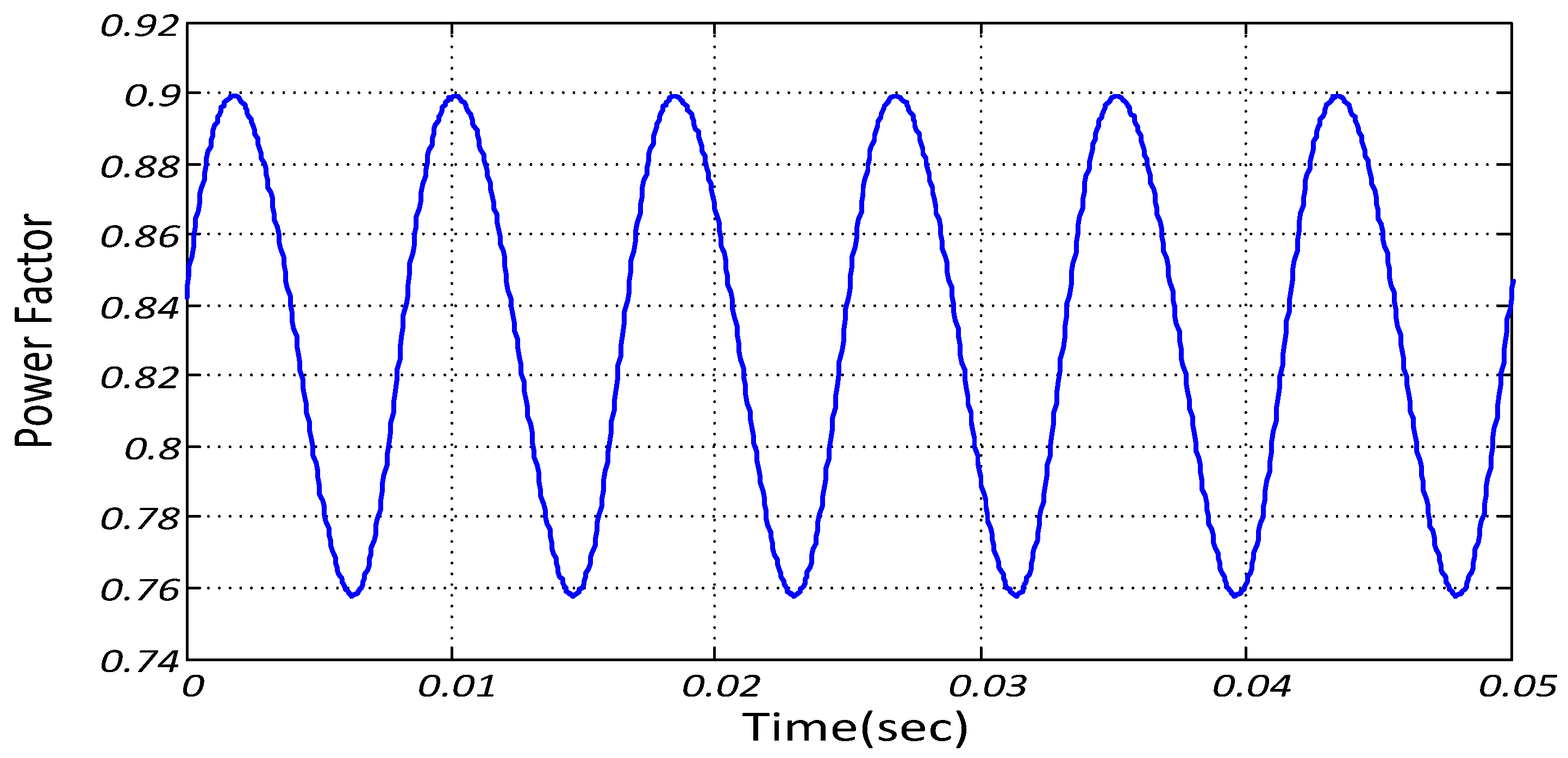
| Without SVC | With SVC | SVC with ASRFC & HVC | |
|---|---|---|---|
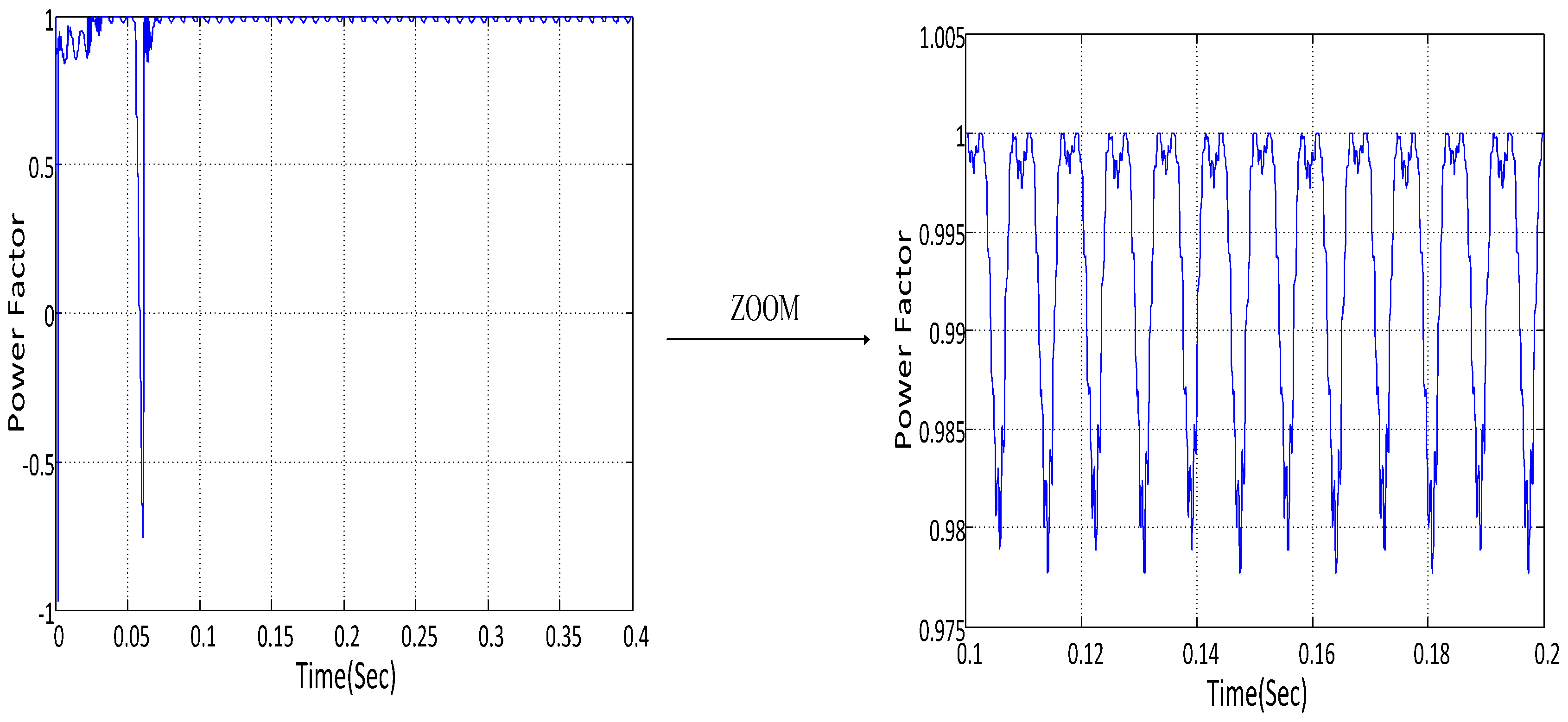
| Average of power factor (%) | 83 | 91.5 | 99 |
| Interval of upper and lower of power factor (%) | 14 | 9 | 2 |
| Without SVC | With SVC | SVC with ASRFC & HVC | |
|---|---|---|---|
| Average of power factor (%) | 83 | 91.5 | 99 (No distortion) |
© 2016 by the authors; licensee MDPI, Basel, Switzerland. This article is an open access article distributed under the terms and conditions of the Creative Commons Attribution (CC-BY) license (http://creativecommons.org/licenses/by/4.0/).
Share and Cite
Farkoush, S.G.; Kim, C.-H.; Rhee, S.-B. THD Reduction of Distribution System Based on ASRFC and HVC Method for SVC under EV Charger Condition for Power Factor Improvement. Symmetry 2016, 8, 156. https://doi.org/10.3390/sym8120156
Farkoush SG, Kim C-H, Rhee S-B. THD Reduction of Distribution System Based on ASRFC and HVC Method for SVC under EV Charger Condition for Power Factor Improvement. Symmetry. 2016; 8(12):156. https://doi.org/10.3390/sym8120156
Chicago/Turabian StyleFarkoush, Saeid Gholami, Chang-Hwan Kim, and Sang-Bong Rhee. 2016. "THD Reduction of Distribution System Based on ASRFC and HVC Method for SVC under EV Charger Condition for Power Factor Improvement" Symmetry 8, no. 12: 156. https://doi.org/10.3390/sym8120156