Abstract
In the present article, we derive optimal spatially varying control fields, which maximize the four-wave mixing efficiency in a four-subband semiconductor asymmetric double quantum well, following analogous works in atomic systems. The control fields coherently prepare the medium, where a weak probe pulse is propagated and eventually converted to a signal pulse at the output. The optimal fields, which maximize the conversion efficiency for a given propagation length, are obtained by applying optimal control theory to a simplified form of propagation equations but are tested with numerical simulations using the full set of Maxwell–Schrödinger equations, which accurately describe the propagation of light pulses in the medium. For short propagation distances, the proposed optimal scheme outperforms a simpler spatially changing control protocol that we recently studied, while for larger distances, the efficiency of both protocols approaches unity. The present work is expected to find application in frequency conversion between light beams, conversion between light beams carrying orbital angular momentum, and nonlinear optical amplification.
1. Introduction
During the last decades, quantum interference related to Electromagnetically Induced Transparency (EIT) has become a major field of research in contemporary quantum optics [1,2,3], with exciting applications, for example, the “stopping” of light [4]. Another important application is four-wave mixing (FWM), which has attracted considerable attention because it is exploited in a vast spectrum of research areas, for example, quantum information processing and storage [5], frequency and orbital angular momentum conversion between light beams [6,7], nonlinear optical amplification [8], etc.
EIT has been also achieved in semiconductor systems, taking advantage of the resemblance between the electronic levels of these systems and atomic systems [9,10,11,12,13,14,15,16]. In this framework, four-wave mixing arising from quantum interference between the intersubband transitions in semiconductor quantum wells has been explored. Many of these works study a system configuration involving four subbands [17,18,19,20]. To improve the rather low mixing efficiency, a few studies make use of an additional (fifth) level [21,22,23], while others [24] exploit coupling of the semiconductor energy levels to the continuum energy spectrum [25,26,27]. Another article utilizes an additional coupling among subbands [28]. The conversion between light beams which carry orbital angular momentum while they propagate in semiconductor system like the one under investigation has been put forward in the excellent studies [29,30]. The common feature of the previously cited papers is the usage of control fields which do not depend on the propagation length. Note that FWM in semiconductor systems is not restricted in the above context but has also been considered in other structures, for example, in quantum dot semiconductor optical amplifiers [31].
To improve mixing efficiency in systems composed of semiconductor quantum wells, we proposed in our recent work [32] the utilization of control fields with spatial variation, which alter along propagation length, influenced by related investigations involving atomic systems [6,7]. Using the typical four-subband configuration, we considered control fields with a constant sum of intensities but with the mixing angle linearly changing as a function of the propagation length. After deriving a simplified model describing propagation, we showed analytically that mixing efficiency converging to one for long distances can be accomplished by the proposed scheme. The analytical findings were numerically confirmed by performing simulations with the full model of Maxwell–Schrödinger equations describing propagation. For large propagation distances the suggested scheme essentially implemented an adiabatic evolution.
In this work, we consider the optimal control fields maximizing the FWM efficiency for a given propagation distance, which were derived in the framework of atomic systems in Ref. [7] using optimal control theory, and apply them to the typical four-subband configuration of a semiconductor quantum-well system. We show analytically using the simplified propagation model, and confirm numerically using the full model, that the optimal protocol attains larger efficiency values than the protocol considered in Ref. [32] for short propagation distances, while for longer distances, both protocols give similar results. The optimal protocol essentially implements a shortcut to adiabaticity [33].
This article is structured as follows. In Section 2, we describe the system, and in Section 3, we describe the simplified model which is used for the derivation of the optimal control fields. In Section 4, we present and discuss simulation results obtained using the full model, while Section 5 summarizes the outcomes of the present work.
2. System Description
The system under study is displayed in Figure 1 and is an asymmetric semiconductor double-quantum well having four subbands, , which can be implemented in a GaAs/AlxGa1−xAs heterosctructure [24]. For the composition described in Ref. [24], the corresponding energies of the levels are meV, meV, meV, and meV. Transitions and are driven by two control fields with center frequencies and wavevectors . These are strong continuous-wave (CW) fields which prepare the corresponding states of the medium in a coherent way. Transition is driven by a weak probe pulse of center frequency and wavevector that propagates along the coherent medium, while transition generates the weak four-wave mixing (FWM) pulse of center frequency and wavevector .
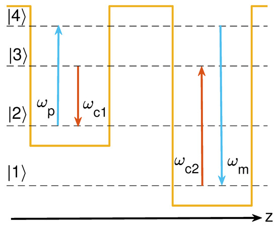
Figure 1.
Schematic representation of the system.
The system is described by the following Hamiltonian, under rotating-wave and electric-dipole approximations,
with detunings , , and Rabi frequencies , , , , where the latter are given using the electric field envelopes and dipole moments of the transitions. The system’s state is written as
with being the probability amplitude corresponding to subband , . Note that these amplitudes change with time, and if we plug Equation (2) into the Schrödinger equation , we obtain a set of coupled differential equations,
To simplify the analysis, we fix the phase mismatch as . For the phenomenologically introduced decay rates, we will use the values from Ref. [30], eV, meV, and meV. Observe that and , relations that we will exploit in the following section.
The propagation of the probe and FWM pulses along the z-direction shown in Figure 1, in the slowly varying envelope approximation, is described by the wave equations
with propagation constants , and N the electron concentration in the semiconductor quantum wells, which come from donors. The typical common value meV/m [30] will be used. Using the following definition for a density matrix element
the wave Equations turn into
3. Methodology
Here, we first obtain a simplified version of propagation equations, based on some reasonable assumptions, and then use them to find the optimal spatial variation of the control fields , maximizing the conversion efficiency from to for a given propagation distance. The optimal fields obtained through this simplified model are evaluated in the following section by applying them to the complete set of original system Equations (3)–(6) and (7)–(8). From Equations (3)–(6) with , we obtain for
which, by setting and , meV (the latter relations come from the observations concerning decay rate values in Section 2), take the form
The probe and FWM pulses, , are much weaker than CW control fields . These strong fields prepare the subsystem comprising states into the dark state
with being the mixing angle of
which depends on the propagation length, while the amplitude is constant. Because , as the probe pulse propagates and the FWM pulse is generated in the coherently prepared medium, matrix elements remain close to their dark state values (16),
On the other hand, states are slightly excited, and therefore, we may consider in first order . Under these assumptions, solving Equations (14)–(15) for the steady-state values of , we obtain in first order regarding
Note that are functions of both the time and the propagation length z, while the considered control fields and the corresponding mixing angle are functions of z only, see Equation (17). In the rest of this section, we concentrate in the spatial dependence of the variables and consider again the time dependence of the probe and FWM pulses in the next section, where we test the control protocol obtained here using the full set of Maxwell–Bloch Equations (3)–(6) and (7)–(8).
By plugging Equations (19) into Equations (10)–(11), we arrive at the following system expressing the propagation of along the semiconductor medium
Using a normalized propagation length
the system takes the form
The propagation distance is equivalent to with
Since is a function of propagation length, it is advantageous to exploit the adiabatic basis of the simplified system matrix (22), consisting of the following eigenstates (with eigenvalues 0 and ).
We can express the “state” vector in terms of the adiabatic basis as
where are the components in the adiabatic basis. The inverse transformation between the components in the original and adiabatic bases is
where we note that the transformation matrix is involutory. Combining the above equations, we obtain the following propagation equations for the state vector in the adiabatic basis
where the spatially dependent function corresponds to
This system is obviously not PT-symmetric, while we emphasize that the derivatives in Equations (27) and (28) are taken with respect to the normalized spatial coordinate .
In our recent work [32], we considered a linear change in with propagation length between the boundary values (29), inspired from corresponding studies in atomic systems [6,7]. In this case and for large values of the propagation distance, it is , thus system (27) evolves adiabatically, and is kept nearly unchanged from its initial value, in which case, . The probe pulse is transformed to the FWM pulse following eigenstate . For a constant rate of change , corresponding to normalized propagation distance , the mixing efficiency is found to be
Figure 2a displays with a dashed green line the mixing efficiency (32) for distances up to the value of m, while Figure 2b shows the detail of the previous figure for shorter distances, up to the value of m. It is obvious that for larger distances, where the transfer becomes more adiabatic, the efficiency converges to one, while for smaller distances, a lower value is obtained.
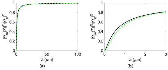
Figure 2.
(a) Mixing efficiency for distances up to m. (b) Detail of the previous figure for distances up to m. The black solid line corresponds to the optimal scheme, while the green dashed line corresponds to the protocol considered in Ref. [32].
In the present study and motivated also by our previous work on atomic systems [7], we apply in the system at hand the optimal rate , which maximizes the mixing efficiency for a specified propagation distance, implementing thus a shortcut to adiabaticity. We will not present the full details of the optimal solution here, which can be found in Refs. [7,34], but rather give the main points of the derivation. With arguments from the theory of optimal control, one can show that the optimal sequence of pulses has the so-called bang–singular–bang form,
where two delta pulses of equal strength at the beginning and end increase the angle instantaneously by an amount , while a constant control in between, called singular in the optimal control terminology, increases linearly with the propagation length . Although at first glance the suggested control protocol appears to be highly irregular, it can be implemented quite easily by linearly changing between the values and , instead of 0 and of the protocol in Ref. [32]. As we shall see in the next section, practically, this means that the boundary values are nonzero. The initial and final jumps in do not affect the original probe and FWM fields, only the adiabatic variables.
We next explain how the optimal values of and can be calculated for a specified propagation distance . The initial delta pulse brings system (27) to , instantaneously, while increases the angle to . Optimal control theory indicates that the ratio should be kept constant during the interval and equal to the value . By taking the derivative and using Equation (27), we find that this is accomplished by the constant control
The value of is found from the terminal condition which, for the pulse-sequence (33), is translated to and, using Equation (34), becomes the following transcendental equation.
From Equation (35), it can be inferred that , and in this range, there is only one optimal value of , which of course depends on the propagation distance appearing in the equation as a parameter. Finally, it is not hard to show that the control sequence (33), when applied to system (27), leads to the efficiency
where we note that Equation (34) has been used to express in terms of the solution of Equation (35), while the latter equation has been also exploited to simplify the expression.
Figure 2a,b show with solid black line the efficiency (36) of the optimal protocol (33) for long and short propagation distances. Compared to the protocol where angle changes linearly with the propagation distance without the initial and final jumps, the optimal sequence gives a better efficiency for shorter distances, while for longer distances, the efficiencies of the two protocols converge. Since the efficiency is determined by the normalized propagation distance given in Equation (23), the optimal method is particularly useful in the cases where there are restrictions on the length of the device and the propagation constant is small or the decay rate is large. From Figure 2a, we observe that the efficiency is an increasing function of the propagation distance, thus any desired efficiency value can be achieved for propagation distances beyond a minimum value determined from this plot. In Section 4, the optimal protocol, derived from the simplified model of propagation (22), is evaluated with simulations of the original propagation model.
4. Results and Analysis
Here, we numerically study the propagation of probe and mixing fields when applying the optimal control fields in the Maxwell–Bloch pair of Equations (3)–(6) and (7)–(8). The fields are taken on resonance, and consequently, , while the rest of model parameters are eV, meV, meV, and meV/m, see Ref. [30]. The control fields (17) have constant amplitude meV, while the mixing angle is varied along the propagation length according to the optimal protocol (33). At the input of the coherently prepared medium, only a weak Gaussian probe pulse is inserted (the mixing pulse is zero there).
with parameters , , and .
Figure 3, Figure 4 and Figure 5 display various propagation results for three distances, 1 m, 10 m, and 100 m. They correspond to the star, circle, and square markers, respectively, shown in Figure 2. We explain these results starting from Figure 3 corresponding to the smallest distance m. The optimal control fields are shown in Figure 3a. Since the initial and final jumps in the mixing angle are found to be rad, by solving Equation (35) with obtained from Equation (23) for m, we observe that normalized does not start from one and end at zero, and, respectively, does not start from zero and end at one. This distinctive behavior of the controls, compared to the protocol where the mixing angle is just linearly varied between 0 and , leads to the higher efficiency achieved by the optimal protocol, demonstrated in Figure 2b for the simplified propagation model and as we will immediately see for the full model also. As we explain in our recent work [35], the nonzero leads to the quick buildup of nonzero populations in the intermediate states, which facilitate the conversion from the probe to the pump field for limited propagation distances, while the nonzero quickly eliminates these intermediate populations when the desired transfer has been completed. Figure 3b displays the normalized peak intensity at the middle of the probe pulse (approximate from simplified model solid yellow, numerical from full model dashed pink) and the corresponding one for the mixing pulse (approximate from simplified model solid orange, numerical from full model dashed blue), throughout the length of propagation. Notice the extremely good agreement of the efficiencies achieved by the simplified and full models. This means that the efficiency of the optimal protocol indicated by the star marker in Figure 2 is indeed acquired by the realistic Maxwell–Bloch model. This efficiency is larger than that obtained using the protocol of Ref. [32] where is changed linearly with distance, see the green dashed line in Figure 2b. Figure 4a,b depict the evolution of the normalized intensity corresponding to the full probe and FWM pulses along the propagation length. The conversion efficiency at the exit m is 0.5826. The results for the larger distance m are plotted in Figure 4. Note from Figure 4c that now the nonzero are smaller than their values for the previous case of smaller propagation distance. The jumps in the mixing angle, found from Equation (35) with obtained from Equation (23) for m, are now rad, much smaller than before. Figure 4d exhibits that the eminent accordance of the results produced by the simplified model, and the full models is also extended for the distance m. The efficiency achieved is increased to 0.9370 because of the longer available distance. For the largest distance m that we consider here, we see from Figure 5a that now it is , , since the jumps in the angle are very small for that distance, rad. In this case, the optimal protocol practically coincides with that of Ref. [32]. There is again an almost perfect agreement between the theoretical and numerical efficiencies. The mixing efficiency at the exit length m rises to the value 0.9934, confirming thus the convergence to one for larger distances.
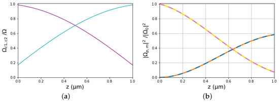
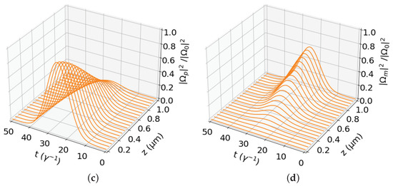
Figure 3.
Control, probe, and FWM pulses for propagation distance m: (a) continuous wave control fields (magenta) and (cyan) as functions of the propagation length z. (b) Spatial variation in the normalized intensity at the middle () of the probe pulse (approximate solid yellow, numerical dashed pink) and of the FWM pulse (approximate solid orange, numerical dashed blue). (c,d) Spatial evolution of the probe and FWM pulses, respectively. The conversion efficiency at the output is .
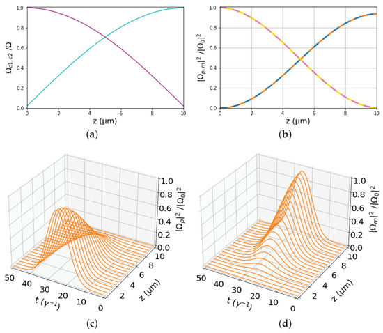
Figure 4.
Same as Figure 3 but for propagation distance m. The conversion efficiency at the output has increased to .
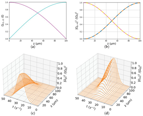
Figure 5.
Same as Figure 3 but for propagation distance m. The conversion efficiency at the output has risen to .
5. Concluding Remarks
We obtained optimal spatially changing control fields, maximizing the four-wave mixing efficiency in a four-subband semiconductor asymmetric double-quantum well for a given propagation distance, according to similar studies in atomic systems. We showed analytically using a simplified model of propagation and confirmed numerically by performing simulations with the full model that for short propagation distances the suggested optimal scheme outperforms another simple spatially varying control protocol that we considered in the recent publication [32]. For larger distances, both protocols achieve similar mixing efficiencies which tend to unity.
Author Contributions
Conceptualization, D.S. and E.P.; methodology, D.S. and E.P.; software, D.S.; validation, D.S. and E.P.; investigation, D.S. and E.P.; writing—original draft preparation, D.S. and E.P.; writing—review and editing, D.S. and E.P.; visualization, D.S.; supervision, D.S. and E.P. All authors have read and agreed to the published version of the manuscript.
Funding
This work was funded by an Empirikion Foundation research grant.
Data Availability Statement
Data are contained within the article.
Conflicts of Interest
The authors declare no conflicts of interest.
Abbreviations
The following abbreviations are used in this manuscript:
| FWM | four-wave mixing |
| CW | continuous wave |
References
- Harris, S.E.; Hau, L.V. Nonlinear Optics at Low Light Levels. Phys. Rev. Lett. 1999, 82, 4611–4614. [Google Scholar] [CrossRef]
- Lukin, M.D. Colloquium: Trapping and manipulating photon states in atomic ensembles. Rev. Mod. Phys. 2003, 75, 457–472. [Google Scholar] [CrossRef]
- Fleischhauer, M.; Imamoglu, A.; Marangos, J.P. Electromagnetically induced transparency: Optics in coherent media. Rev. Mod. Phys. 2005, 77, 633–673. [Google Scholar] [CrossRef]
- Hau, L.V.; Harris, S.E.; Dutton, Z.; Behroozi, C.H. Light speed reduction to 17 metres per second in an ultracold atomic gas. Nature 1999, 397, 594–598. [Google Scholar] [CrossRef]
- Phillips, N.B.; Gorshkov, A.V.; Novikova, I. Light storage in an optically thick atomic ensemble under conditions of electromagnetically induced transparency and four-wave mixing. Phys. Rev. A 2011, 83, 063823. [Google Scholar] [CrossRef]
- Lee, C.Y.; Wu, B.H.; Wang, G.; Chen, Y.F.; Chen, Y.C.; Yu, I.A. High conversion efficiency in resonant four-wave mixing processes. Opt. Express 2016, 24, 1008–1016. [Google Scholar] [CrossRef]
- Stefanatos, D.; Smponias, A.; Hamedi, H.R.; Paspalakis, E. Ultimate conversion efficiency bound for the forward double-Λ atom–light coupling scheme. Opt. Lett. 2020, 45, 6090–6093. [Google Scholar] [CrossRef]
- Li, H.C.; Ge, G.Q.; Zubairy, M.S. Achieving nonlinear optical modulation via four-wave mixing in a four-level atomic system. Phys. Rev. A 2018, 97, 053826. [Google Scholar] [CrossRef]
- Serapiglia, G.B.; Paspalakis, E.; Sirtori, C.; Vodopyanov, K.L.; Phillips, C.C. Laser-Induced Quantum Coherence in a Semiconductor Quantum Well. Phys. Rev. Lett. 2000, 84, 1019–1022. [Google Scholar] [CrossRef]
- Sadeghi, S.M.; Leffler, S.R.; Meyer, J. Quantum interference and nonlinear optical processes in the conduction bands of infrared-coupled quantum wells. Phys. Rev. B 1999, 59, 15388–15394. [Google Scholar] [CrossRef]
- Sadeghi, S.M.; van Driel, H.M.; Fraser, J.M. Coherent control and enhancement of refractive index in an asymmetric double quantum well. Phys. Rev. B 2000, 62, 15386–15389. [Google Scholar] [CrossRef]
- Frogley, M.D.; Dynes, J.F.; Beck, M.; Faist, J.; Phillips, C.C. Gain without inversion in semiconductor nanostructures. Nat. Mater. 2006, 5, 175. [Google Scholar] [CrossRef]
- Yang, W.X.; Yang, X.; Lee, R.K. Carrier-envelope-phase dependent coherence in double quantum wells. Opt. Express 2009, 17, 15402–15408. [Google Scholar] [CrossRef] [PubMed]
- Antón, M.; Carreño, F.; Calderón, O.G.; Melle, S. All-optical control of the time delay in a one-dimensional photonic bandgap formed by double-quantum-wells. Opt. Commun. 2008, 281, 644–654. [Google Scholar] [CrossRef]
- Li, J.H. Controllable optical bistability in a four-subband semiconductor quantum well system. Phys. Rev. B 2007, 75, 155329. [Google Scholar] [CrossRef]
- Sun, H.; Gong, S.; Niu, Y.; Jin, S.; Li, R.; Xu, Z. Enhancing Kerr nonlinearity in an asymmetric double quantum well via Fano interference. Phys. Rev. B 2006, 74, 155314. [Google Scholar] [CrossRef]
- Hao, X.; Li, J.; Liu, J.; Song, P.; Yang, X. Efficient four-wave mixing of a coupled double quantum-well nanostructure. Phys. Lett. A 2008, 372, 2509–2513. [Google Scholar] [CrossRef]
- Yang, W.X.; Hou, J.M.; Lee, R.K. Highly efficient four-wave mixing via intersubband transitions in InGaAs/AlAs coupled double quantum well structures. J. Mod. Opt. 2009, 56, 716–721. [Google Scholar] [CrossRef]
- She, Y.C.; Zheng, X.J.; Wang, D.L. Enhancement of four-wave mixing process in a four-level double semiconductor quantum well. Chin. Phys. B 2014, 23, 124202. [Google Scholar] [CrossRef]
- She, Y.C.; Zheng, X.J.; Wang, D.L.; Ding, J.W. High Efficiency Four-Wave Mixing with Relaxation Coupling of Longitude-Optical Phonons in Semiconductor Quantum Wells. Commun. Theor. Phys. 2015, 63, 599. [Google Scholar] [CrossRef]
- Sun, H.; Fan, S.; Zhang, H.; Gong, S. Tunneling-induced high-efficiency four-wave mixing in asymmetric quantum wells. Phys. Rev. B 2013, 87, 235310. [Google Scholar] [CrossRef]
- Liu, S.; Yang, W.X.; Zhu, Z.; Lee, R.K. Giant enhanced four-wave mixing efficiency via two-photon resonance in asymmetric quantum wells. Laser Phys. Lett. 2015, 12, 095202. [Google Scholar] [CrossRef][Green Version]
- Sun, D.; Zhang, H.; Sun, H.; Li, X.; Li, H. Tunneling-induced highly efficient four-wave mixing in asymmetric double quantum wells. Laser Phys. Lett. 2018, 15, 045208. [Google Scholar] [CrossRef]
- Liu, S.; Yang, W.X.; Chuang, Y.L.; Chen, A.X.; Liu, A.; Huang, Y.; Lee, R.K. Enhanced four-wave mixing efficiency in four-subband semiconductor quantum wells via Fano-type interference. Opt. Express 2014, 22, 29179–29190. [Google Scholar] [CrossRef] [PubMed]
- Faist, J.; Capasso, F.; Sirtori, C.; West, K.W.; Pfeiffer, L.N. Controlling the sign of quantum interference by tunnelling from quantum wells. Nature 1997, 390, 589–591. [Google Scholar] [CrossRef]
- Schmidt, H.; Campman, K.L.; Gossard, A.C.; Imamoǧlu, A. Tunneling induced transparency: Fano interference in intersubband transitions. Appl. Phys. Lett. 1997, 70, 3455–3457. [Google Scholar] [CrossRef]
- Faist, J.; Sirtori, C.; Capasso, F.; Pfeiffer, L.N.; West, K.W.; Sivco, D.L.; Cho, A.Y. Chapter 2 Quantum Interference Effects in Intersubband Transitions. In Semiconductors and Semimetals; Elsevier: Amsterdam, The Netherlands, 1999; Volume 62, pp. 101–128. [Google Scholar] [CrossRef]
- Yu, C.; Sun, L.; Zhang, H.; Chen, F. High efficiency four-wave mixing in double asymmetry quantum dots. Optik 2019, 180, 295–301. [Google Scholar] [CrossRef]
- Zhang, Y.; Wang, Z.; Qiu, J.; Hong, Y.; Yu, B. Spatially dependent four-wave mixing in semiconductor quantum wells. Appl. Phys. Lett. 2019, 115, 171905. [Google Scholar] [CrossRef]
- Wang, Z.; Zhang, Y.; Paspalakis, E.; Yu, B. Efficient spatiotemporal-vortex four-wave mixing in a semiconductor nanostructure. Phys. Rev. A 2020, 102, 063509. [Google Scholar] [CrossRef]
- Flayyih, A.H.; Al-Khursan, A.H. Theory of four-wave mixing in quantum dot semiconductor optical amplifiers. J. Phys. D Appl. Phys. 2013, 46, 445102. [Google Scholar] [CrossRef]
- Stefanatos, D.; Avouri, F.; Paspalakis, E. Efficient four-wave mixing in four-subband semiconductor quantum wells using spatially modulated control fields with a linearly varying mixing angle. J. Appl. Phys. 2023, 134, 094302. [Google Scholar] [CrossRef]
- Guéry-Odelin, D.; Ruschhaupt, A.; Kiely, A.; Torrontegui, E.; Martínez-Garaot, S.; Muga, J.G. Shortcuts to adiabaticity: Concepts, methods, and applications. Rev. Mod. Phys. 2019, 91, 045001. [Google Scholar] [CrossRef]
- Stefanatos, D.; Paspalakis, E. Optimal shape of STIRAP pulses for large dissipation at the intermediate level. Quantum Inf. Process. 2021, 20, 391. [Google Scholar] [CrossRef]
- Stefanatos, D.; Paspalakis, E. Optimal shortcuts of stimulated Raman adiabatic passage in the presence of dissipation. Philos. Trans. R. Soc. A Math. Phys. Eng. Sci. 2022, 380, 20210283. [Google Scholar] [CrossRef]
Disclaimer/Publisher’s Note: The statements, opinions and data contained in all publications are solely those of the individual author(s) and contributor(s) and not of MDPI and/or the editor(s). MDPI and/or the editor(s) disclaim responsibility for any injury to people or property resulting from any ideas, methods, instructions or products referred to in the content. |
© 2024 by the authors. Licensee MDPI, Basel, Switzerland. This article is an open access article distributed under the terms and conditions of the Creative Commons Attribution (CC BY) license (https://creativecommons.org/licenses/by/4.0/).