
Investigation of Buckling Behavior of Cracked FG Cylindrical Panels Reinforced by Graphene Platelets

Department of Naval Architecture and Ocean Engineering, Hongik University, Jochiwon, Sejong 30016, Republic of Korea
Symmetry 2023, 15(12), 2162; https://doi.org/10.3390/sym15122162
Submission received: 3 November 2023
/
Revised: 26 November 2023
/
Accepted: 1 December 2023
/
Published: 5 December 2023
(This article belongs to the Special Issue Applied Mechanics, Engineering and Modeling - Volume II)
Abstract
:The buckling behavior of a functionally graded graphene-platelet-reinforced composite (FG-GPLRC) was traditionally investigated, mostly with respect to its undamaged structures. In this context, the current study investigated the buckling behavior of an FG-GPLRC cylindrical panel with an anti-symmetric central crack by introducing a 2-D extended natural element method (XNEM). The displacement was basically expressed with the first-order shear deformation theory (FSDT) and approximated using Laplace interpolation functions (for the non-singular displacement part) and crack-tip singular functions (for the singular displacement part) without grid refinement around the crack tips. The complex numerical manipulation on the curved shell surface was resolved by geometrically transforming the curved shell surface to a 2-D planar rectangular NEM grid. The painstaking numerical locking was suppressed by adopting the concept of a stabilized MITC3+ shell element. The validity of the developed numerical method was examined through a benchmark test, and the fundamental buckling loads of cracked FG-GPLRC cylindrical panels were investigated in depth by changing the major parameters. The numerical results also included a comparison with the FG-CNTRC. The numerical results indicated that the developed numerical method effectively predicts the buckling loads with reasonable accuracy, and that the fundamental buckling load of cracked FG-GPLRC cylindrical panels are remarkably influenced by the inclination angle and length of the crack as well as the other associated parameters.
1. Introduction
Nowadays, conventional glass fiber reinforcement for polymer composites is being progressively replaced with graphene platelet (GPL) reinforcement. The main reason for this is because the structural stiffness is dramatically increased, even when only small amounts of GPLs are introduced to the polymer matrix [1,2]. Graphene platelets are characterized by higher stiffness and lower production costs than carbon nanotubes (CNTs) [3,4]. Thus, graphene-platelet-reinforced composites (GPLRCs) have been highlighted as a next-generation advanced composite material, and their mechanical behaviors have been intensively investigated [5,6,7]. Even though the production cost is lower than CNT-reinforced composites, the cost of GPLRCs is still much higher than conventional fiber-reinforced composites. Therefore, reinforcement with GPLs is limited to low-volume fractions, and this limitation has naturally invoked the idea of a functionally graded material (FGM), which is characterized by the non-uniform and continuous functional distribution of constituent particles to enhance the target performance by resolving the material discontinuity-induced problems [8,9,10]. The functional distribution, which is usually made through the thickness, may not only minimize the total amount of GPLs but also maximize the desired mechanical behavior [11,12]. Shen [13] and Ke et al. [14] introduced intentional thickness-wise distributions of GPLs according to the notion of FGM.
Thereafter, several purposefully devised distribution patterns, such as FG-V, FG-O, FG-X and FG-Λ were introduced, and the GPL-reinforced composites with these functional distributions have been called by functionally graded GPL-reinforced composites (FG-GPLRCs). The different thickness-wise distribution of GPLs affects the structural stiffness and mass matrices, which in turn influence the mechanical responses of FG-GPLRC structures such as the static bending, free vibration and buckling. Therefore, the parametric characteristics of these FG-GPLRC structures have been intensively investigated using either analytical methods or numerical methods [6,15]. Research has shown that the mechanical behaviors of FG-GPLRC structures are remarkably influenced by the distribution pattern of GPLs.
Regarding to the studies on buckling of FG-GPLRC structures, Shen et al. [16] analyzed the thermal buckling and post-buckling strengths of FG-GPLRC laminate plates by applying a multi-scale approach to the higher-order shear deformation theory. Wu et al. [17] investigated the thermal buckling and post-buckling of FG-GPLRC plates by applying the differential quadrature-based iteration scheme to FSDT. Song et al. [18] examined the static bending and buckling of FG-GPLRC plates using analytical and numerical methods within the framework of FSDT. Huang et al. [19] investigated the nonlinear buckling behavior of FG-GPLRC shallow arches subjected to elastic rotational constraints based on the virtual work principle. Wang et al. [20] parametrically analyzed the torsional buckling of FG-GPLRC cylindrical shells by the finite element method. Kiani [21] analyzed the thermal buckling behavior of FG-GPLRC conical shells by combining FSDT, Donnell kinematic postulates and von Kármán geometry nonlinearity. Mao and Zhang [22] investigated the buckling and post-buckling behaviors of FG-GPLRC piezoelectric plates using the differential quadrature method (DQM) and a direct iterative scheme within the framework of FSDT. Thai et al. [23] proposed a NURBS formulation for free vibration, buckling and bending analyses of multilayer FG-GPLRC plates based on the four-variable refined plate theory. Shahgholian et al. [24] investigated the buckling behavior of FG-RPLRC porous cylindrical shell by applying the Rayleigh–Ritz method to FSDT. Karimi Zeverdejani et al. [25] analyzed the buckling and post-buckling of FG-GPLRC laminated composite plates by applying the incremental–iterative Ritz method to FSDT with von Kármán nonlinearity. Allahkarami [26] analyzed the dynamic thermal buckling behavior of FG-GPLRC annular plate by applying the generalized DQM to FSDT. Zhang et al. [27] presented a multiscale numerical method to analyze the static, dynamic, and buckling behaviors of FG beams with a randomly graded GPL distribution.
As revealed from the above relevant literature survey, prior studies on the buckling behavior of FG-GPLRC structures have been limited to intact structures that have not been damaged by cracks. In other words, the buckling behavior of cracked structures has been rarely studied. However, micro-cracking [28] may be induced within nanocomposite-reinforced GPLs by various abnormal external loadings such as thermo-mechanical impact. The occurrence of a crack damages the surrounding region, which weakens the overall structural stiffness of the nanocomposites, so the consideration of cracks in buckling analysis and buckling-proof design is essential. For this reason, this study presents an in-depth investigation of a cracked FG-GPLRC cylindrical panel and its buckling behavior, along with the major parameters which govern the behavior. For the buckling analysis of cracked cylindrical panels, an extended mesh-free method is introduced in order to effectively capture the crack-tip singularity by adding the crack-tip singular functions [29] without the painstaking grid refinement around crack tips.
The FG-GPLRC cylindrical panel is modeled as an isotropic material and its effective mechanical properties are calculated by employing the Halphin–Tsai micromechanical model [30]. The displacement of cracked cylindrical panel is expressed based on FSDT by introducing the crack-tip singular functions to 2-D NEM [31,32], in which high smooth Laplace interpolation (L/I) functions are used. A central crack within the FG-GPLRC cylindrical panel is modeled by separating the nodes lying on the crack to avoid the painstaking grid refinement around the crack. The cracked curved shell surface is mapped to a 2-D planar cracked rectangular NEM grid to avoid complex numerical manipulation, and the stabilized MITC3+ shell elements are adopted to suppress the troublesome locking phenomenon [33,34]. The developed numerical method, called the 2-D extended NEM (XNEM) is verified through a benchmark test, and the buckling behavior of the cracked [35,36] FG-GPLRC cylindrical panel is examined in depth through parametric experiments by changing the major parameters which govern the behavior. The major parameters are the inclination angle and length of central crack, the volume fraction and functional distribution pattern of GPLs, the aspect ratio and shell radius of the cylindrical panel and the boundary conditions. In addition, a comparison with an FG-CNTRC cylindrical panel is also presented, for a comparative understanding of the buckling behavior of cracked FG-GPLRC cylindrical panels.
2. FG-GPLRC Cylindrical Panel
Figure 1a depicts a cylindrical panel reinforced by graphene platelets (GPLs) in which a crack is located within the central region. A cartesian coordinate is sat on the panel neutral surface with the relation of , and the discrepancy between the mid- and neutral surfaces is denoted by [29]. The current study chose the neutral surface as the reference surface because the bending strain vanishes on this surface, not on the mid-surface. The geometric dimensions of the cracked cylindrical panel are governed by radius , length , sub-tended angle , and uniform thickness . Graphene platelets in this study are distributed through the thickness with a specific functional gradient. Figure 1b depicts the four primitive GPL gradient patterns used in this study, where GPLs are uniformly dispersed in FG-U while the patterns are rich near the mid-surface in FG-O, at the top region in FG-X, and at the bottom region in FG-Λ, respectively.
Denoting and as the volume fractions of GPLs and the underlying matrix, two functions are in the following physical relation of
in which the GPL volume fraction has different thickness functions expressed by [5]
depending on the GPL distribution pattern, where the total GPL volume fraction is calculated as [37]
with the GPL mass fraction and two densities and of the GPL and matrix.
In general, GPLs are assumed to be uniformly distributed within the matrix and act as effective rectangular solid fibers with length , width , and thickness , and the GPLRCs are modeled as an isotropic body with the homogenized effective material properties. The effective elastic modulus of GPLRCs is estimated by the Halphin–Tsai micromechanical model [31], which gives
with
Here, and are the elastic moduli of GPLs and matrix, and and denote the geometric parameters determined by
Meanwhile, the effective values of density and Poisson’s ratio of GPLRC are calculated by
using the simplest linear rule of mixtures [8].
Referring to Figure 2, an anti-symmetric central crack existing within the cylindrical panel has a crack length and the inclination angle to the shell axis, where the center of crack coincides with the center point of cylindrical panel. The cracked cylindrical panel is subjected to the external in-plane pressure in the circumferential direction and allowed to move in the shell axis direction. The polar coordinates are introduced to two ends of central crack in order to define the singular functions which will be given later. The buckling load by the external in-plane compression is predicted, and its dependence on the angle and length of the crack, the panel geometric dimensions, and the amounts and patterns of GPLs are investigated. Thus, the crack angle and length and the panel length and width are taken as variables for the parametric investigation.
Based on the first-order shear deformation shell theory [38], the displacement is expressed as
with the translation part and the rotational part . This theory provides an accurate solution for the relatively thin cylindrical panels which are dealt with in the current study. Denoting as the nodal vector at the panel neutral surface, the compatibility relations are expressed as [38,39]
with . Here, and are the and partial differential matrices defined by [2]
with and . Then, one can obtain the constitutive relations given by [38]
3. Natural Element Buckling Load Approximation
In this section, the numerical approximation of critical buckling load of cracked FG-CNTRC cylindrical panel is addressed. The displacement field is expressed by combining the non-singular L/I functions in 2-D NEM and the crack-tip singular functions. The numerical approximation is performed on the 2-D planar NEM by transforming the real curved panel neutral surface to 2-D planar NEM grid. The concept of MITC3+ shell element is adopted to suppress the shear locking phenomenon of bending-dominated thin structures.
For the buckling analysis of cracked FG-GPLRC cylindrical panel by 2-D NEM, the panel neutral surface is firstly discretized into a finite number of 3-node Delaunay triangles, as depicted in Figure 3. In the current study, the central crack is modeled by separating the nodes lying on the crack except for two crack tip nodes. As an extended natural element method (XNEM), the displacement is approximated as
with L/I functions [32,33] and enriched by adding the crack-tip singular functions and which are defined by [29,30]
Here, two distinct polar coordinates are defined at two crack tips , as depicted in Figure 2, and the subscript indicates the -th node within the NEM grid composed of nodes and Delaunay triangles; indicates the non-singular nodal vector at node and denotes the singular nodal vector corresponding to the k-th singular function at two crack tip nodes.
The derivation of the L/I function and its manipulation on the real cylindrical surface are complicated. To overcome this problem in the current work, the physical NEM grid on the real cylindrical surface and the computational NEM grid on the planar rectangle are correlated by newly introducing a geometry transformation defined by
Then, L/I functions are transferred to , and the relations of and introduce the inverse Jacobi matrix given by
The partial derivatives and in Equations (12) and (13) defined on the cylindrical surface are switched to
on the 2-D planar NEM grid according to the chain rule.
Introducing Equation (21) into Equations (12) and (13) results in and in which and are replaced with and :
Then, the present enriched NEM approximations of the bending-membrane strain in Equation (10) and the transverse shear (T/S) strain in Equation (11) lead to
with . Here, and denote and , respectively, and the former is computed on the 2-D NEM grid while the latter is computed directly on the shell surface (Similarly for and ).
However, the proposed NE approximation (24) of the non-singular T/S strain using L/I functions (i.e., the first term on the right hand side in Equation (24)) may cause shear-membrane locking [8,9]. One effective way to suppress the locking is to indirectly interpolate the T/S strains using the idea of MITC3+ shell element [40], as described in Appendix A. The analytic calculation of Equations (A1) and (A2) in the Appendix A using Equations (11) and (15), together with the chain rule between the physical and master coordinates and in Figure 3, leads to
Here, are the element-wise matrices expressed in terms of and , and are the non-singular element-wise nodal vectors.
Meanwhile, the matrix equations of linear buckling problem can be obtained from the virtual work principle given by
where the virtual strain energy and the virtual work done in our problem are defined by [29]
with the external buckling load and the deviation of the neutral surface from the mid-surface.
Then, substituting the previous Equations (14) and (15) and (23)–(25) into Equation (26) results in the linear eigenvalue equations given by
to compute the critical buckling loads and the corresponding buckling modes . Here, three stiffness matrices introduced in this paper are defined by
where, , , , , , , with .
Meanwhile, the matrix in Equation (31), which is modified from introduced in Equation (15) is defined by
with the shear correction factor , the largest side length of Delaunay triangles, and a positive shear stabilization constant [41]. The shear modulus matrix was modified to stabilize further the MITC3+ shell element, and the value of is determined through the preliminary experiment [42]. Figure 4 shows a flowchart for the buckling analysis of cracked FG-GPLRC cylindrical panel by the present 2-D XNEM.
4. Results and Discussion
The numerical formulae in Section 3 were coded and combined into the previously developed NEM program [29] for the buckling analysis of plates. Two stiffness matrices and in Equations (30) and (32) were constructed with 7 Gauss points while was constructed with 1 Gauss point. Referring to Figure 2, the density of the NEM grid was chosen as from the benchmark experiment, which will be given later. The density and pattern of the NEM grid was slightly altered in order to effectively model the inclined central cracks [43], and a total of twelve lowest buckling modes were extracted. The computed buckling loads were calibrated as with . Three kinds of boundary conditions, free (F), simply supported (S), and clamped (C) are considered in this paper, where the latter two are enforced as
at or . Note that is excluded from Equation (35) when the clamped condition is applied to the edge at or , to allow for movement along the shell axis.
First, the convergence of the present method to the grid density of the NEM was examined using a clamped intact aluminum cylindrical panel with the geometric dimensions of , and . The material properties of aluminum are and . As given in Table 1, the first non-dimensional critical buckling loads show a uniform convergence to the grid density. A NEM grid leads to the relative percentage difference less than 5.0%, so this grid density was used for the remaining numerical experiments, unless otherwise specified.
Next, the reliability of the present method was examined by comparing it with the results obtained by the phase field formulation (PFF) [44,45]. A clamped metal–ceramic FG cylindrical panel with the geometric dimensions was used for the above convergence test. These geometry dimensions were used to maintain consistency with the reference [44], and the above aluminum was used for metal and alumina with the material properties and is taken for ceramic. The ceramic volume fraction is governed by the power-law function given by . Intact and three different crack angles and five different ceramic power-law indices were considered, where the relative crack length is set by 0.3. The NEM grid density was set by through the preliminary test. The shear stabilization parameter in Equation (33) was determined as according to the change of NEM grid pattern along the crack inclination angle, and the computed calibrated buckling loads (CBL) are compared in Table 2 and Figure 5. The developed method shows a reasonable agreement with PFF such that the maximum relative differences are −6.573% in and 7.713% in . Meanwhile, the first and second buckling loads show a uniform decrease when increasing the value of power-law index because the panel structural stiffness decreases as the relative volume of relatively stiffer ceramic reduces in proportion to .
Next, ceramic and metal in the above FG cylindrical panel was replaced with an Epoxy matrix and GPLs. The elastic moduli and Poisson’s ratios of matrix and GPLs are , , and , and the geometry dimensions of GPLs are , , respectively. The buckling loads were computed for different values of GPL mass fraction , crack inclination angle , relative crack length and GPL distribution pattern, and the stabilization parameter was chosen by . The non-dimensional fundamental buckling loads are represented in Table 3, and two lowest buckling modes of four different crack inclination angles are represented in Figure 6. The influence of the crack inclination angle on the buckling mode shape can be clearly observed.
Next, the fundamental buckling load was parametrically investigated with respect to the major parameters. The geometry dimensions are , the pattern and mass fraction of GPL are 0.4% and FG-U, and the relative crack length and the boundary condition are 0.3 and CCCC, unless otherwise stated. Figure 7a represents the plots for the different crack inclination angle , where the magnitude of increases in proportion to the GPL mass fraction . This is because the buckling stiffness of cylindrical panel increases when increasing the amount of GPLs. Meanwhile, it can be observed that the fundamental buckling load increases proportionally to the crack inclination angle, because the more horizontal the crack alignment is, the higher the buckling stiffness is. Figure 7b represents the effect of the GPL distribution pattern on the fundamental buckling load, where FG-X shows the highest level while FG-O displays the lowest level. This is because the buckling stiffness of panel becomes larger as GPLs with relatively higher elastic modulus become biased at the top and bottom surfaces. This explanation can be justified by the fact that the fundamental buckling loads of FG-U and FG-Λ with uniform or linearly varying GPL distributions are positioned between FG-X and FG-O.
Figure 8a,b represents the plots for different boundary conditions and different GPL distribution patterns, respectively, where a combination of four characteristics composed of C and S denotes a combination of boundary conditions specified to the panel sides ①, ②, ③ and ④, referring to Figure 3. It is seen that the increase in the fundamental buckling load proportional to the crack inclination angle is slightly saturated for CCCC, and this saturation trend appears at all the GPL distribution patterns. Meanwhile, regarding the effect of the boundary conditions, CCCC and SSSS produce the highest and lowest levels, respectively. However, the differences among CCCC, CSCS and SCSC are shown to be insensitive as the crack alignment becomes horizontal.
Figure 9a represents the plots for different crack inclination angles, where the fundamental buckling load uniformly decreases in proportion to the relative crack length. This is because the buckling stiffness becomes smaller as the cracked length becomes longer, which becomes more apparent as the crack alignment becomes vertical. Figure 9b represents plots for different crack inclination angles, where the fundamental buckling load shows a decrease trend along with the increase in the shell radius. This is because the buckling stiffness in the circumferential direction becomes smaller proportionally to the shell radius .
Next, the dependence of fundamental buckling load on the panel aspect ratio was investigated with being kept at . It can be observed from Figure 10 that the fundamental buckling load becomes smaller proportionally to the aspect ratio. It is because the increase in circumferential width reduces the panel buckling stiffness when the external in-plane pressure is applied in the circumferential direction, as shown in Figure 2. Meanwhile, it can also be observed that the reduction rate becomes dull as the aspect ratio becomes larger.
Finally, the fundamental buckling loads were also computed by replacing the GPLs with CNTs (carbon nanotubes) with the matrix material remaining unchanged. The (10, 10) single-walled CNTs [46] with the orthotropic material properties given in Table 4 were used, where it is assumed that and [16]. The effective mechanical properties of FG-CNTC cylindrical panel are calculated as:
using the modified linear rule of mixtures (MLRM). Here, indicates the CNT efficiency parameters which depend on the CNT total volume fraction [47].
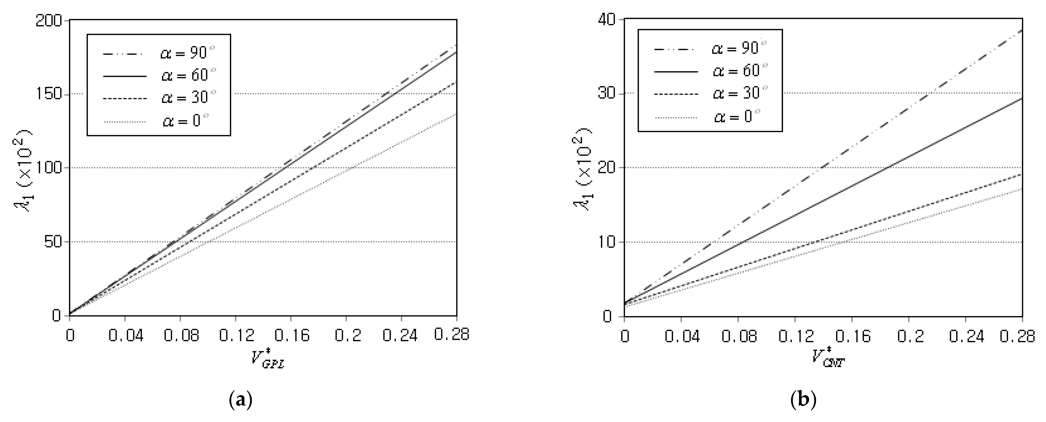
Figure 11 comparatively represents the and plots for different crack inclination angles, where the fundamental buckling loads for both cases linearly increase when increasing the GPL and CNT volume fractions. In addition, the relative orders in the magnitude of among four different crack angles are the same for both FG-GPLRC and FG-CNTRC. However, the absolute magnitudes of are quite different, such that the fundamental buckling load of FG-CNTRC is almost five times as small as that of the FG-GPLRC. Thus, it has been found that FG-GPLRC is much effective for the buckling resistance design than FG-CNTRC for the same volume fraction.
The numerical results demonstrate that the buckling loads of cracked FG-GPLRC cylindrical panels were reliably predicted, and their characteristics were investigated in depth. However, the crack was modeled by separating the nodes lying on the crack, so the crack inclination angle and length are slightly subjected to the density and pattern of the NEM grid.
5. Conclusions
The buckling response of FG-GPLRC cylindrical panel with an anti-symmetric central crack was investigated in depth by introducing an extended natural element method (XNEM). The numerical method was developed by combining L/I functions and the crack-tip singular functions in the framework of a 2-D planar NEM without grid refinement around the crack tips. The developed XNEM-based numerical method was validated through a benchmark test, and the effects of major parameters on the buckling behavior of cracked FG-GPLRC cylindrical panels were examined in depth. The numerical results provide us the following main findings:
- The developed 2-D XNEM effectively analyzes the buckling of FG-GPLRC cylindrical panel having a central crack, with reasonable numerical accuracy;
- The fundamental buckling load linearly increases proportional to the amount of GPLs, regardless of the crack inclination angle. The relative order in the fundamental buckling loads among the four GPL distribution patterns is FG-X > FG-U > FG-Λ > FG-O;
- The fundamental buckling load increases proportionally to the crack inclination angle, but this increase trend is slightly saturated for CCCC, regardless of the GPL distribution pattern. However, it uniformly decreases proportionally to the crack’s relative length.
- For the same volume fraction, the buckling stiffness of the cylindrical panel reinforced with GPLs is almost five times as large as that of a CNT-reinforced cylindrical panel.
The present method successfully and reliably predicts and investigates the buckling behavior of FG-GPLRC cylindrical panels. Thus, the developed 2D-XNEM and the numerical results could be useful for the buckling analysis and buckling-proof design of cracked cylindrical nanocomposites reinforced with GPLs and CNTs. However, the crack inclination angle and length are somewhat restricted by the NEM grid; a grid-independent crack modeling approach, such as phase field formulation (PFF), would merit further study as a research topic in future work.
Funding
This work was supported by the National Research Foundation of Korea (NRF) grant funded by the Korea government (MSIT) (RS-2023-00240618, 2020R1A2C1100924).
Conflicts of Interest
The author declares no conflict of interest.
Nomenclature
| Radius, subtended angle and thickness of the cylindrical panel | |
| Width and length of the cylindrical panel | |
| Neutral surface and its radial distance from the panel midsurface | |
| Volume fractions of GPL and the matrix | |
| Total volume fractions of GPLs and CNTs | |
| Elastic moduli of GPLRC, matrix and GPL | |
| Length, thickness and width of GPL | |
| Poisson’s ratios of GPLRC, matrix and GPL | |
| Densities of GPLRC, matrix and GPL | |
| Length and inclination angle of central crack | |
| Translation components at the neutral surface of cylindrical panel | |
| Rotational components at the neutral surface | |
| Non-singular nodal vector at node J | |
| Singular nodal vector corresponding to the k-th singular function | |
| In-plane strain components | |
| In-plane stress components | |
| Transverse shear strains and stresses | |
| Physical and computational NEM grids | |
| J-th critical buckling load and buckling mode | |
| Shear correction factor | |
| Shear stabilization parameter | |
| Panel aspect ratio and relative crack length | |
| CNT efficiency parameters | |
| Power-law index and calibrated J-th critical buckling load |
Appendix A
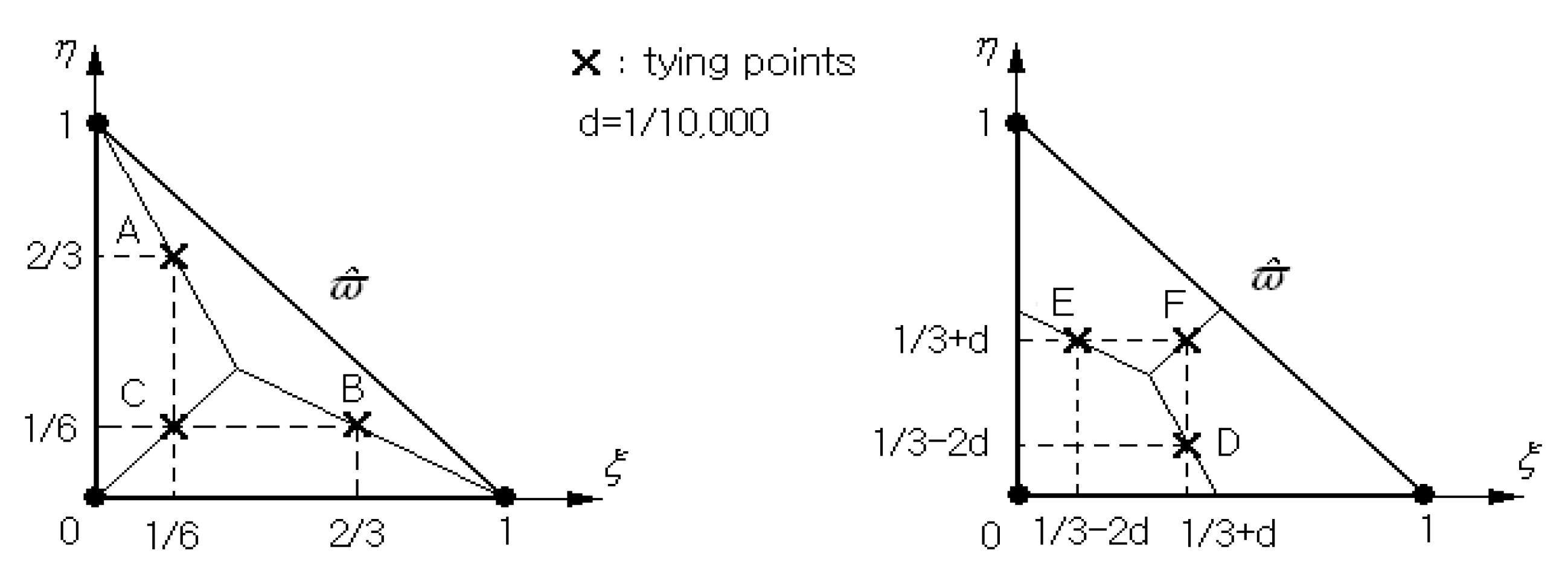
Referring to Figure 3, each triangle in the physical NEM grid is mapped to the 3-node master element depicted in Figure A1. Next, using the Lagrange-type bilinear shape functions [48], the triangle-wise non-singular nodal vectors , the NEM approximation of non-singular displacement part is re-expressed. Then, according to the notion of MITC3+ shell element, the element-wise non-singular T/S strains are indirectly interpolated as
with . Where, A, B, C, D, E and F indicate six tying points shown in Figure A1.
Figure A1.
Tying points A, B, C, D, E and F within the master triangular element for interpolating the non-singular element-wise T/S strains .
Figure A1.
Tying points A, B, C, D, E and F within the master triangular element for interpolating the non-singular element-wise T/S strains .
References
- Ramanathan, T.; Abdala, A.A.; Stankovich, S.; Dikin, D.A.; Herrera-Alonso, M.; Piner, R.D.; Adamson, D.H.; Schniepp, H.C.; Chen, X.; Ruoff, R.S.; et al. Functionalized graphene sheets for polymer nanocomposites. Nat. Nanotechnol. 2008, 3, 327–331. [Google Scholar] [CrossRef]
- Cho, J.R. Free vibration analysis of functionally graded porous cylindrical panels reinforced with graphene platerets. Nanomaterials 2023, 13, 1441. [Google Scholar] [CrossRef]
- Young, R.J.; Kinloch, I.A.; Gong, I.; Novoselov, K.S. The mechanics of graphene nano-composites: A review. Compos. Sci. Technol. 2012, 72, 1459–1476. [Google Scholar] [CrossRef]
- Rafiee, M.A.; Rafiee, J.; Wang, Z.; Song, H.; Yu, Z.Z.; Koratkar, N. Enhanced mechanical properties of nanocomposites at low graphene content. ACS Nano 2009, 3, 3884–3890. [Google Scholar] [CrossRef] [PubMed]
- Shen, H.S.; Xiang, Y.; Lin, F. Nonlinear vibration of functionally graded graphene-reinforced composite laminated plates in thermal environments. Comput. Methods Appl. Mech. Eng. 2017, 319, 175–193. [Google Scholar] [CrossRef]
- Zhao, S.; Zhao, Z.; Yang, Z.; Ke, L.L.; Kitipornchai, S.; Yang, J. Functionally graded graphene reinforced composite structures: A review. Eng. Struct. 2020, 210, 110339. [Google Scholar] [CrossRef]
- Kumar, A.; Sharma, K.; Dixit, A.R. Carbon nanotube- and graphene-reinforced multiphase polymeric composites: Review on their properties and applications. J. Mater. Sci. 2020, 55, 2682–2724. [Google Scholar] [CrossRef]
- Cho, J.R.; Oden, J.T. Functionally graded material: A parametric study on thermal-stress characteristics using the Crack-Nicolson-Galerkin scheme. Comput. Methods Appl. Mech. Eng. 2000, 188, 17–38. [Google Scholar] [CrossRef]
- Birman, V.; Byrd, L.W. Modeling and analysis of functionally graded materials and structures. Appl. Mech. Rev. 2007, 60, 195–216. [Google Scholar] [CrossRef]
- Zhou, W.; Ai, S.; Chen, M.; Zhang, R.; He, R.; Pei, Y.; Fang, D. Preparation and thermodynamic analysis of the porous ZrO2/(ZrO2+ Ni) functionally graded bolted joint. Compos. Part B 2015, 82, 13–22. [Google Scholar] [CrossRef]
- Cho, J.R.; Ha, D.Y. Optimal tailoring of 2D volume-fraction distributions for heat-resisting functionally graded materials using FDM. Comput. Methods Appl. Mech. Eng. 2002, 191, 3195–3211. [Google Scholar] [CrossRef]
- Nikbakht, S.; Kamarian, S.; Shakeri, M. A review on optimization of composite structures, Part II: Functionally graded materials. Compos. Struct. 2019, 214, 83–102. [Google Scholar] [CrossRef]
- Shen, H.S. Nonlinear bending of functionally graded carbon nanotube-reinforced composite plates in thermal environments. Compos. Struct. 2009, 91, 9–19. [Google Scholar] [CrossRef]
- Ke, L.L.; Yang, J.; Kitipornchai, S. Nonlinear free vibration of functionally graded carbon nanotube-reinforced composite beams. Compos. Struct. 2010, 92, 676–683. [Google Scholar] [CrossRef]
- García-Macías, E.; Rodríguez-Tembleque, L.; Sáez, A. Bending and free vibration analysis of functionally graded graphene vs. carbon nanotube reinforced composite plates. Compos. Struct. 2018, 186, 123–138. [Google Scholar] [CrossRef]
- Shen, H.-S.; Xiang, Y.; Lin, F. Thermal buckling and postbuckling of functionally graded graphene-reinforced composite laminated plates resting on elastic foundations. Thin-Walled Struct. 2017, 118, 229–237. [Google Scholar] [CrossRef]
- Wu, H.; Kitipornchai, S.; Yang, J. Thermal buckling and postbuckling of functionally graded graphene nanocomposite plates. Mater. Des. 2017, 132, 430–441. [Google Scholar] [CrossRef]
- Song, M.; Yang, J.; Kitipornchai, S. Bending and buckling analyses of functionally graded polymer composite plates reinforced with graphene nanoplaterets. Compos. Part B Eng. 2018, 134, 106–113. [Google Scholar] [CrossRef]
- Huang, Y.; Yang, Z.; Liu, A.; Fu, J. Nonlinear buckling analysis of functionally graded graphene reinforced composite shallow arches with elastic rotational constraints under uniform radial load. Materials 2018, 11, 910. [Google Scholar] [CrossRef]
- Wang, Y.; Feng, C.; Zhao, Z.; Lu, F.; Yang, J. Torsional buckling of graphene platerets (GPLs) reinforced functionally graded cylindrical shell with cutout. Compos. Struct. 2018, 197, 72–79. [Google Scholar] [CrossRef]
- Kiani, Y. Buckling of functionally graded graphene reinforced conical shells under external pressure in thermal environment. Compos. Part B Eng. 2019, 156, 128–137. [Google Scholar] [CrossRef]
- Mao, J.J.; Zhang, W. Buckling and post-buckling analyses of functionally graded graphene reinforced piezoelectric plate subjected to electric potential and axial forces. Compos. Struct. 2019, 216, 392–405. [Google Scholar] [CrossRef]
- Thai, C.H.; Ferreira, A.J.M.; Tran, T.D.; Phung-Van, O. Free vibration, buckling and vbending analyses of multilayer functionally graded graphene nanoplaterets reinforced composite plates using the NURBS formulation. Compos. Struct. 2019, 220, 749–759. [Google Scholar] [CrossRef]
- Shahgholian, D.; Safarpour, M.; Rahimi, A.R.; Alibeigloo, A. Buckling analyses of functionally graded graphene-reinforced porous cylindrical shell using the Rayleigh–Ritz method. Acta Mech. 2020, 231, 1887–1902. [Google Scholar] [CrossRef]
- Zeverdejani, M.K.; Beni, Y.T.; Kiani, Y. Multi-scale buckling and post-buckling analysis of functionally graded laminated composite plates reinforced by defective graphene sheets. Int. J. Struct. Stab. Dyn. 2020, 20, 2050001. [Google Scholar] [CrossRef]
- Allahkarami, F. Dynamic buckling of functionally graded multilayer graphene nanocomposite annular plate under different boundary conditions in thermal environment. Eng. Comput. 2022, 38, 583–606. [Google Scholar] [CrossRef]
- Zhang, L.; Xu, Z.; Gao, M.; Xu, R.; Wang, G. Static, dynamic and buckling responses of random functionally graded beams reinforced by graphene platerets. Eng. Struct. 2023, 291, 116476. [Google Scholar] [CrossRef]
- Wang, K.; Chen, L.; Wu, J.; Toh, M.L.; He, C.; Yee, A.F. Epoxy nanocomposites with highly exfolidated clay: Mechcanical properties and fracture mechanisms. Macromolecules 2005, 38, 788–800. [Google Scholar] [CrossRef]
- Cho, J.R. Buckling analysis of functionally graded plates resting on elastic foundation by natural element method. Steel Compos. Struct. 2022, 44, 157–167. [Google Scholar]
- Halphin, J.C.; Kardos, J.L. The Haplin-Tsai equations: A review. Polym. Eng. Sci. 1976, 16, 344–352. [Google Scholar]
- Sukumar, N.; Moran, B.; Belytschko, T. The natural element method in solid mechanics. Int. J. Numer. Methods Eng. 1998, 43, 839–887. [Google Scholar] [CrossRef]
- Cho, J.R.; Lee, H.W. A Petrov-Galerkin natural element method securing the numerical integration accuracy. J. Mech. Sci. Technol. 2006, 20, 94–109. [Google Scholar] [CrossRef]
- Pitkaranta, J. The problem of membrane locking in finite element analysis of cylindrical shells. Numer. Math. 1992, 61, 523–542. [Google Scholar] [CrossRef]
- Cho, J.R.; Oden, J.T. Locking and boundary layer in hierarchical models for thin elastic structures. Comput. Methods Appl. Mech. Eng. 1997, 149, 33–48. [Google Scholar] [CrossRef]
- Bayesteh, H.; Mohammadi, S. XFEM fracture analysis of shells: The effect of crack tip enrichments. Comput. Mater. Sci. 2011, 50, 2793–2813. [Google Scholar] [CrossRef]
- Nasirmanesh, A.; Mohammadi, S. Eigenvalue buckling analysis of cracked functionally graded cylindrical shells in the framework of the extended finite element method. Compos. Struct. 2017, 159, 548–566. [Google Scholar] [CrossRef]
- Yang, B.; Yang, J.; Kitipornchai, S. Thermoelastic analysis of functionally graded graphene reinforced rectangular plates based on 3D elasticity. Meccanica 2017, 52, 2275–2292. [Google Scholar] [CrossRef]
- Reddy, J.N. Mechanics of Laminated Composite Plates and Shells, Theory and Analysis, 2nd ed.; CRC Press: Boca Raton, FL, USA, 2004. [Google Scholar]
- Niu, Y.; Yao, M. Linear and nonlinear vibrations of graphene platelet reinforced composite tapered plates and cylindrical panels. Aerosp. Sci. Technol. 2021, 115, 106798. [Google Scholar] [CrossRef]
- Lee, Y.; Lee, P.-S.; Bathe, K.-J. The MITC3+ shell finite element and its performance. Comput. Struct. 2014, 138, 12–23. [Google Scholar] [CrossRef]
- Chau-Dinh, T. Analysis of shell structures by an improved 3-node triangular flat shell element with a bubble function and cell-based strain smoothing. Thin-Walled Struct. 2023, 182, 110222. [Google Scholar] [CrossRef]
- Lyly, M.; Stenberg, R.; Vihinen, T. A stable bilinear element for the Reissner-mindlin plate model. Comput. Methods Appl. Mech. Eng. 1993, 110, 343–357. [Google Scholar] [CrossRef]
- Cho, J.R.; Lee, H.W. Calculation of stress intensity factors in 2-D linear fracture mechanics by Petrov–Galerkin natural element method. Int. J. Numer. Methods Eng. 2014, 98, 819–839. [Google Scholar] [CrossRef]
- Torabi, J.; Ansari, R. Numerical investigation on the buckling and vibration of cracked FG cylindrical panels based on the phase-field formulation. Eng. Fract. Mech. 2020, 228, 106895. [Google Scholar] [CrossRef]
- Ambati, M.; Gerasimov, T.; De Lorenzis, L. A review on phase-field models of brittle fracture and a new fast hybrid formulation. Comput. Mech. 2015, 55, 383–405. [Google Scholar] [CrossRef]
- Liang, Z.; Gou, J.J.; Zhang, C.; Wang, B.; Kramer, L. Investigation of molecular interactions between (10, 10) single-walled nanotube and Epon 862 resin/DETDA curing agent molecules. Mater. Sci. Eng. A 2004, 365, 228–234. [Google Scholar] [CrossRef]
- Zhu, P.; Lei, Z.X.; Liew, K.M. Static and free vibration analyses of carbon nanotube-reinforced composite plates using finite element method with first order shear deformation plate theory. Compos. Struct. 2012, 94, 1450–1460. [Google Scholar] [CrossRef]
- Baker, E.B.; Oden, J.T.; Carey, G.F. Finite Elements: An Introoduction; Prentice-Hall: Hoboken, NJ, USA, 1981; Volume 1. [Google Scholar]
Figure 1.
A cracked FG-GPLRC cylindrical panel: (a) geometric dimensions; and (b) functional GPL distribution patterns.
Figure 1.
A cracked FG-GPLRC cylindrical panel: (a) geometric dimensions; and (b) functional GPL distribution patterns.

Figure 2.
External in-plane pressure in the cracked FG-GPLRC cylindrical panel.
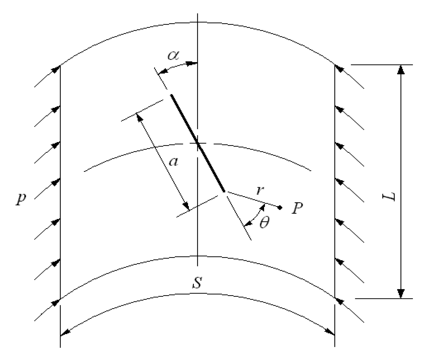
Figure 3.
The L/I functions defined on the cracked 2-D planar NEM grid and their mapped functions to the cracked cylindrical surface.
Figure 3.
The L/I functions defined on the cracked 2-D planar NEM grid and their mapped functions to the cracked cylindrical surface.
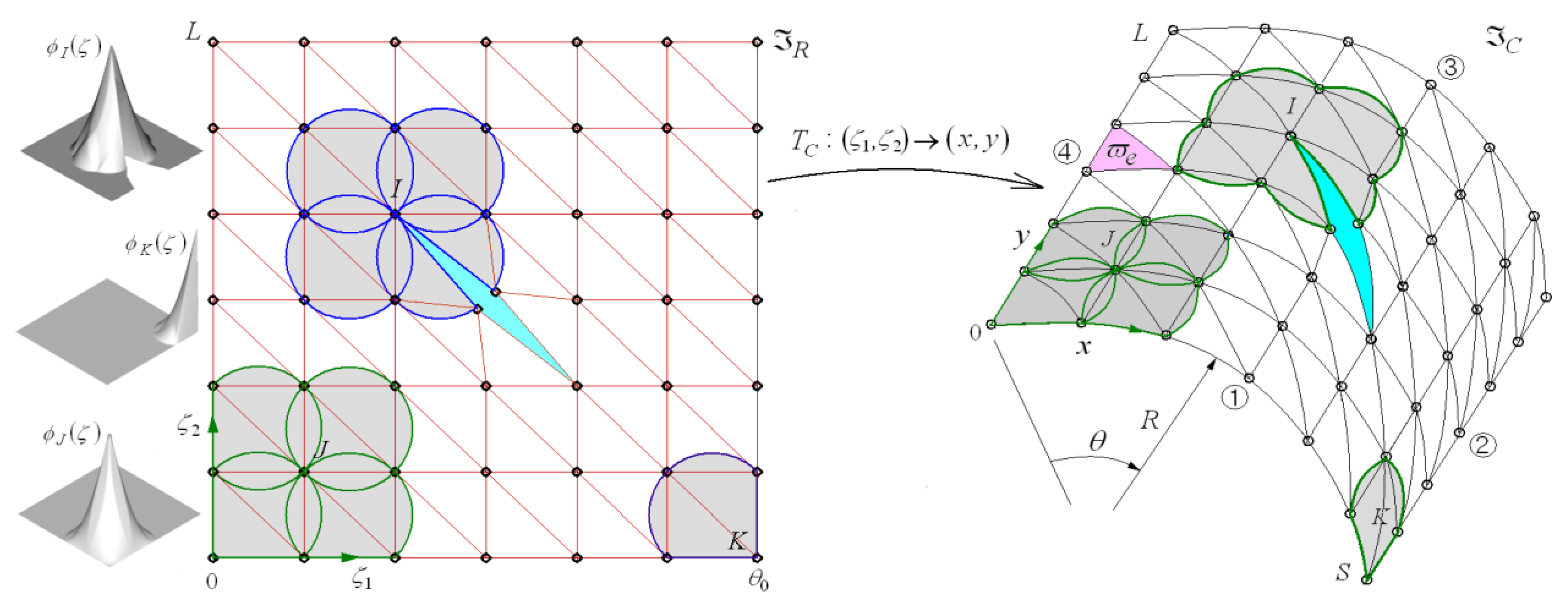
Figure 4.
A flowchart for the cracked buckling analysis by the proposed 2-D XNEM-based locking-free numerical method.
Figure 4.
A flowchart for the cracked buckling analysis by the proposed 2-D XNEM-based locking-free numerical method.

Figure 5.
Comparison of curves for difference crack inclination angles (Intact/PFF [44]): (a) first buckling mode; and (b) second buckling mode.
Figure 5.
Comparison of curves for difference crack inclination angles (Intact/PFF [44]): (a) first buckling mode; and (b) second buckling mode.
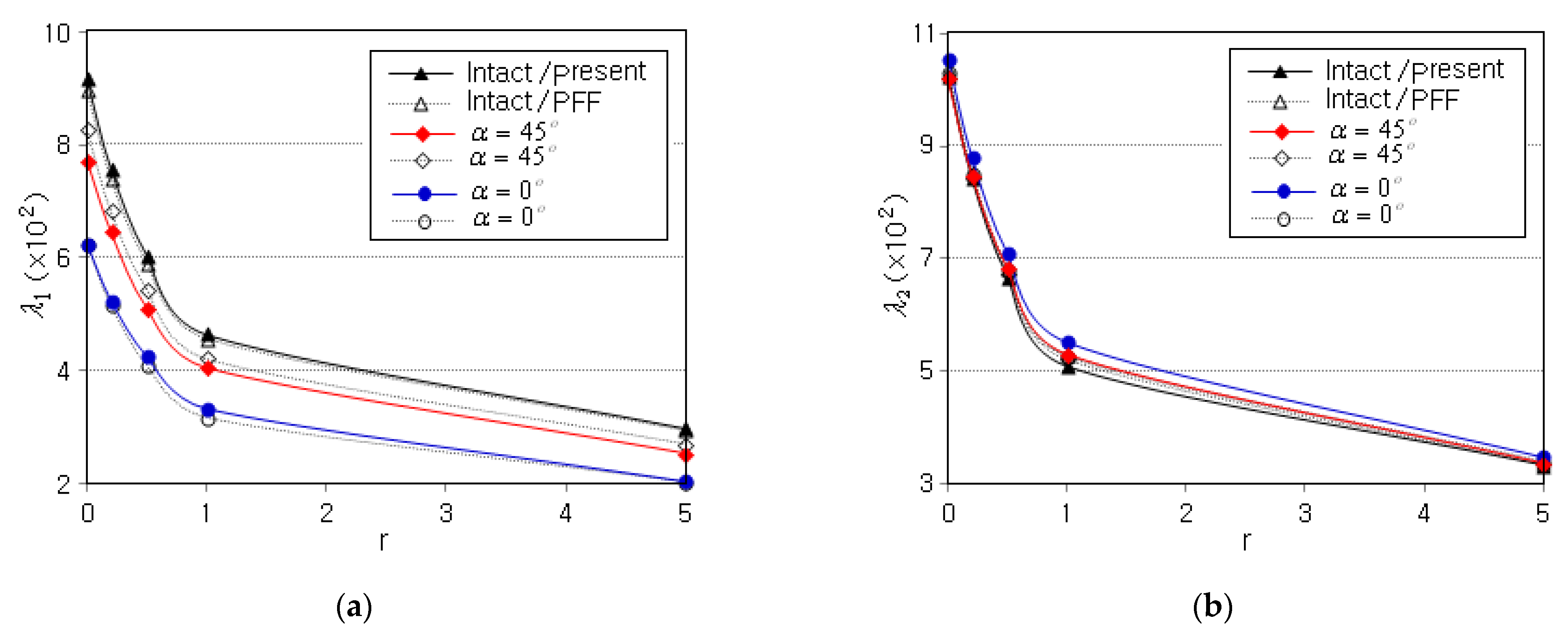
Figure 6.
Buckling modes of clamped FG-GPLRC cylindrical panel for four different crack inclination angles (FG-U, ): (a) first mode; and (b) second mode.
Figure 6.
Buckling modes of clamped FG-GPLRC cylindrical panel for four different crack inclination angles (FG-U, ): (a) first mode; and (b) second mode.

Figure 7.
Variation of non-dimensional fundamental buckling load versus the GPL mass fraction for: (a) four crack inclination angles; and (b) four GPL distribution patterns ().
Figure 7.
Variation of non-dimensional fundamental buckling load versus the GPL mass fraction for: (a) four crack inclination angles; and (b) four GPL distribution patterns ().
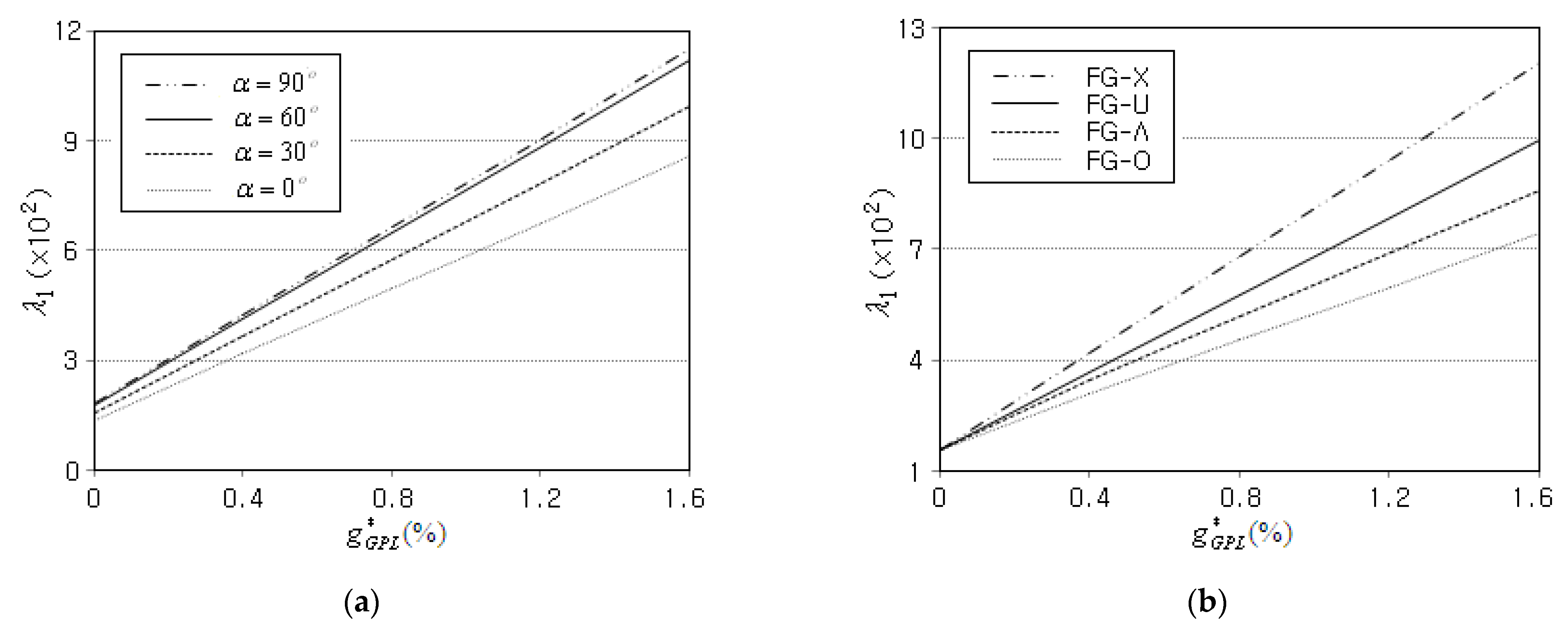
Figure 8.
Variation of non-dimensional fundamental buckling load to the crack inclination angle for: (a) four boundary conditions (FG-O); and (b) four GPL distribution patterns.
Figure 8.
Variation of non-dimensional fundamental buckling load to the crack inclination angle for: (a) four boundary conditions (FG-O); and (b) four GPL distribution patterns.

Figure 9.
Variation of non-dimensional fundamental buckling load to: (a) the relative crack length (FG-X); and (b) the shell radius R (FG-O).
Figure 9.
Variation of non-dimensional fundamental buckling load to: (a) the relative crack length (FG-X); and (b) the shell radius R (FG-O).

Figure 10.
Variation of the non-dimensional fundament buckling load to the crack inclination angle (FG-X) for: (a) ; (b) ; (c) ; and (d) .
Figure 10.
Variation of the non-dimensional fundament buckling load to the crack inclination angle (FG-X) for: (a) ; (b) ; (c) ; and (d) .
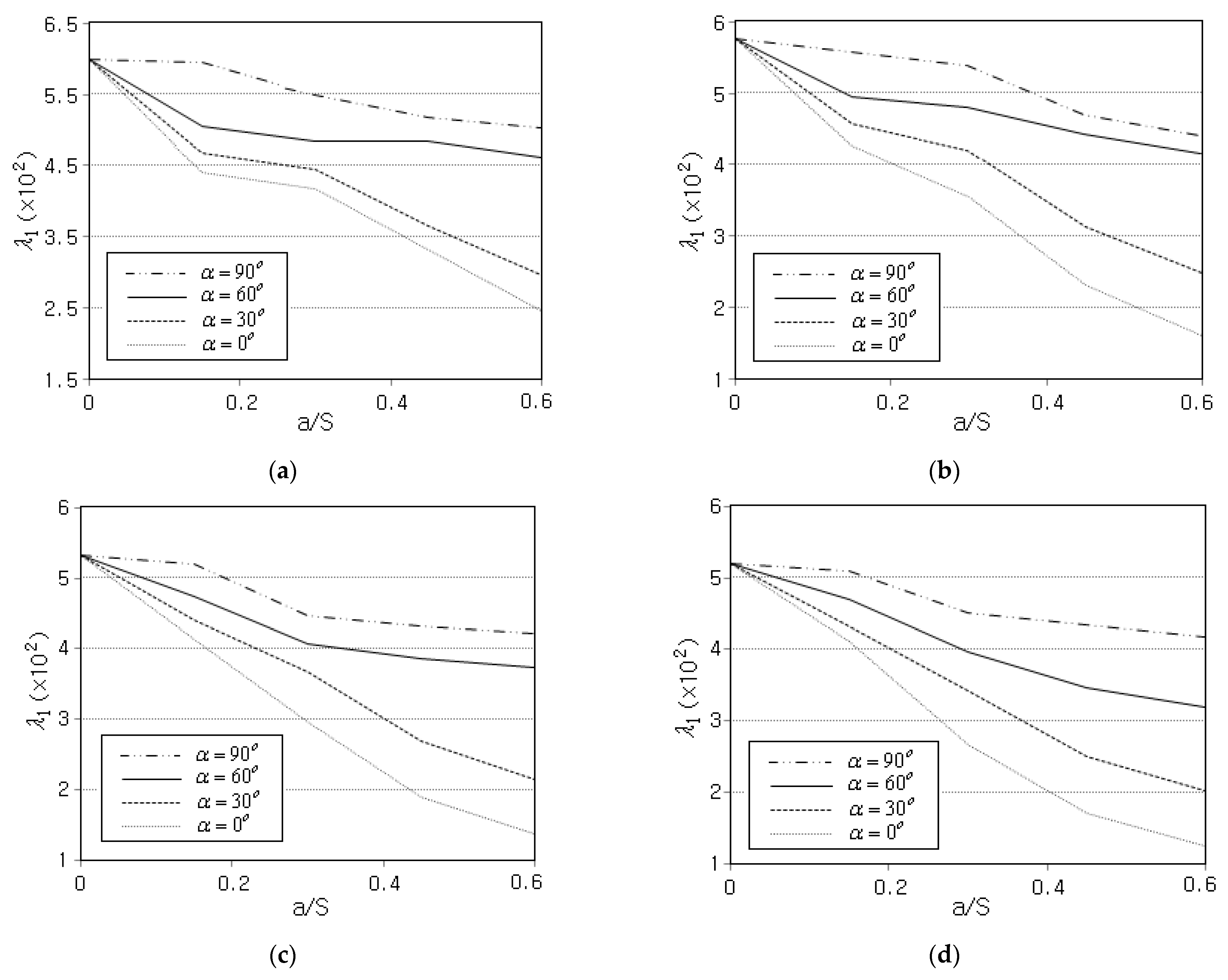
Figure 11.
Comparison of non-dimensional fundamental buckling loads between GPLRC and CNTRC (FG-U): (a) GPLRC; and (b) CNTRC.
Figure 11.
Comparison of non-dimensional fundamental buckling loads between GPLRC and CNTRC (FG-U): (a) GPLRC; and (b) CNTRC.

Table 1.
Convergence of first non-dimensional critical buckling load of intact aluminum cylindrical panel ( CCCC).
Table 1.
Convergence of first non-dimensional critical buckling load of intact aluminum cylindrical panel ( CCCC).
| Items | Grid Density | ||||||
|---|---|---|---|---|---|---|---|
| 333.36 | 285.52 | 256.11 | 236.35 | 222.14 | 211.44 | 203.13 | |
| 64.11 | 40.56 | 26.08 | 16.35 | 9.36 | 4.09 | - | |
Table 2.
Comparison of first two non-dimensional critical buckling loads of FG cracked cylindrical panel ( , CCCC).
Table 2.
Comparison of first two non-dimensional critical buckling loads of FG cracked cylindrical panel ( , CCCC).
| Method | CBL | ||||||
|---|---|---|---|---|---|---|---|
| 0 | 0.2 | 0.5 | 1 | 5 | |||
| PFF [44] | Intact | 896.21 | 739.69 | 589.83 | 456.89 | 293.36 | |
| 1034.66 | 855.02 | 682.26 | 528.50 | 338.72 | |||
| 0 | 624.52 | 514.50 | 409.52 | 316.63 | 202.72 | ||
| 1030.11 | 851.56 | 679.88 | 526.91 | 336.65 | |||
| 45 | 826.08 | 681.53 | 543.20 | 420.56 | 269.69 | ||
| 1021.45 | 843.85 | 673.15 | 521.30 | 334.09 | |||
| 90 | 857.26 | 706.91 | 562.89 | 435.41 | 280.80 | ||
| 1023.02 | 845.07 | 674.02 | 521.88 | 334.56 | |||
| Present | Intact | 916.85 | 758.12 | 604.18 | 464.34 | 297.71 | |
| 1025.20 | 843.15 | 667.27 | 508.09 | 332.64 | |||
| 0 | 624.28 | 523.97 | 425.01 | 332.89 | 203.84 | ||
| 1054.42 | 879.79 | 707.95 | 550.78 | 346.69 | |||
| 45 | 771.78 | 644.99 | 519.25 | 404.32 | 252.76 | ||
| 1019.26 | 848.31 | 682.25 | 529.94 | 336.25 | |||
| 90 | 855.52 | 704.49 | 556.60 | 422.59 | 277.56 | ||
| 1080.01 | 901.52 | 726.01 | 559.74 | 359.09 | |||
Table 3.
Non-dimensional fundamental buckling loads of FG-GPLRC cylindrical panels ( CCCC).
| (%) | GPL Distribution Pattern | |||||
|---|---|---|---|---|---|---|
| FG-U | FG-O | FG-X | FG-Λ | |||
| 0.4 | 0 | 0.3 | 316.77 | 271.86 | 356.96 | 302.75 |
| 0.6 | 152.32 | 130.05 | 173.50 | 155.12 | ||
| 30 | 0.3 | 366.94 | 306.21 | 420.80 | 343.82 | |
| 0.6 | 214.71 | 184.49 | 242.64 | 198.83 | ||
| 60 | 0.3 | 413.23 | 338.52 | 480.32 | 383.46 | |
| 0.6 | 362.90 | 305.70 | 415.85 | 335.89 | ||
| 90 | 0.3 | 424.03 | 345.90 | 497.97 | 393.26 | |
| 0.6 | 374.39 | 308.85 | 436.16 | 349.08 | ||
| 0.8 | 0 | 0.3 | 496.85 | 405.29 | 558.78 | 456.70 |
| 0.6 | 239.29 | 194.36 | 281.43 | 238.49 | ||
| 30 | 0.3 | 576.37 | 452.59 | 682.77 | 519.28 | |
| 0.6 | 337.31 | 275.97 | 392.74 | 297.36 | ||
| 60 | 0.3 | 649.06 | 497.25 | 781.48 | 578.72 | |
| 0.6 | 570.04 | 454.20 | 675.06 | 502.39 | ||
| 90 | 0.3 | 666.03 | 508.43 | 812.90 | 598.02 | |
| 0.6 | 588.09 | 466.46 | 702.20 | 530.33 | ||
Table 4.
Material properties of (10, 10) single-walled CNTs ().
| Young’s Moduli (GPa) | Poisson’s Ratios | Shear Moduli (GPa) | ||||||
|---|---|---|---|---|---|---|---|---|
| 5646.6 | 7080.0 | 7080.0 | 0.175 | 0 | 0 | 1944.5 | 1944.5 | 1944.5 |
Disclaimer/Publisher’s Note: The statements, opinions and data contained in all publications are solely those of the individual author(s) and contributor(s) and not of MDPI and/or the editor(s). MDPI and/or the editor(s) disclaim responsibility for any injury to people or property resulting from any ideas, methods, instructions or products referred to in the content. |
© 2023 by the author. Licensee MDPI, Basel, Switzerland. This article is an open access article distributed under the terms and conditions of the Creative Commons Attribution (CC BY) license (https://creativecommons.org/licenses/by/4.0/).
Share and Cite
MDPI and ACS Style
Cho, J.-R. Investigation of Buckling Behavior of Cracked FG Cylindrical Panels Reinforced by Graphene Platelets. Symmetry 2023, 15, 2162. https://doi.org/10.3390/sym15122162
AMA Style
Cho J-R. Investigation of Buckling Behavior of Cracked FG Cylindrical Panels Reinforced by Graphene Platelets. Symmetry. 2023; 15(12):2162. https://doi.org/10.3390/sym15122162
Chicago/Turabian StyleCho, Jin-Rae. 2023. "Investigation of Buckling Behavior of Cracked FG Cylindrical Panels Reinforced by Graphene Platelets" Symmetry 15, no. 12: 2162. https://doi.org/10.3390/sym15122162
Note that from the first issue of 2016, this journal uses article numbers instead of page numbers. See further details here.