Bloch Analysis of Electromagnetic Waves in Twist-Symmetric Lines


Laboratoire d’Électronique et Électromagnétisme, Sorbonne Université, F-75005 Paris, France
*
Authors to whom correspondence should be addressed.
Symmetry 2019, 11(5), 620; https://doi.org/10.3390/sym11050620
Submission received: 15 March 2019
/
Revised: 21 April 2019
/
Accepted: 23 April 2019
/
Published: 3 May 2019
(This article belongs to the Special Issue Higher Symmetries and Its Application in Microwave Technology, Antennas and Metamaterials)
Abstract
:We discuss here under which conditions a periodic line with a twist-symmetric shape can be replaced by an equivalent non-twist symmetric structure having the same dispersive behavior. To this aim, we explain the effect of twist symmetry in terms of coupling among adjacent cells through higher-order waveguide modes. We use several waveguide modes to accurately derive the dispersion diagram of a line through a multimodal transmission matrix. With this method, we can calculate both the phase and attenuation constants of Bloch modes, both in shielded and open structures. In addition, we use the higher symmetry of these structures to further reduce the computational cost by restricting the analysis to a subunit cell of the structure instead of the entire unit cell. We confirm the validity of our analysis by comparing our results with those of a commercial software.
1. Introduction
A higher symmetric periodic line is characterized by its invariance under a geometrical transformation other than a translation. The higher symmetry resulting from a combination of a rotation and a translation is called twist (or screw) symmetry [1,2,3,4]. In an N-fold twist symmetry, if the period is p, a subunit cell ( of the entire unit cell) is translated along the periodicity axis and twisted radians around the same axis. Figure 1a,b shows 2-fold and 4-fold twist symmetric lines, respectively.
Recent studies on higher-symmetric structures have revealed interesting characteristics such as a reduced dispersion and wider and stronger stop bands [5,6,7,8,9,10,11,12]. These characteristics have led to numerous applications in different areas such as wideband lens antennas [13], cost-effective gap-waveguide technology [14,15], leaky-wave antennas [16], and leakage reduction in waveguide transitions [17]. All these studies use commercial software to perform periodic analyses on a unit cell of periodicity. Despite its accuracy, this approach is not valid if the structure is open (radiating line) and does not give any physical insight about the impact of the twist operation on the periodic line. Only in Reference [5] was an equivalent circuit proposed for a line based on a coaxial cable. However, that circuit considers the interaction between adjacent cells only through the fundamental TEM mode of the coaxial line. In this paper, we will show that such an approach can fail if dense lines are studied.
As proved in those papers, the advantages of higher-symmetric structures over simpler periodic ones stimulate now the urge to understand where the difference between the two categories arises, for instance, to explain the source of different dispersive behaviors of the structures in Figure 1a,c on the basis of fundamental electromagnetic theory. In addition, there is a need for fast and efficient analysis methods for higher symmetric structures. This paper answers both of these needs by first showing the different coupling mechanism occurring in higher-symmetric and non-higher-symmetric structures and then by formulating a Bloch analysis method that only takes into account a partial unit cell, thus accelerating the calculation procedure.
In this work, we first classify periodic structures with twist symmetry into two groups: reducible and irreducible. The former group consists of structures that are equivalent to periodic structures with a reduced period and no twist symmetry, while the latter group consists of those of which the higher symmetry cannot be reduced to an equivalent periodic structure with a reduced period. We show that the couplings between cells through higher-order modes are the cause of the difference between these two groups. We quantify this effect by defining a multimodal transmission matrix to formulate a Bloch analysis. Finally, we formulate, for the first time, the eigenvalue problem based on a twist symmetry operator [4] by means of a transmission-matrix approach. This restricts the problem to a subregion of a unit cell and, therefore, reduces the computational cost of the analysis. It also helps to explain how the higher-order modes affect the reducibility of the structure.
2. Reducibility of Twist-Symmetric Structures
In this section, we define the reducibility of twist-symmetric structures to non-twist periodic lines. We will state under which assumptions this property holds by means of a multimodal transmission-matrix approach capable to perform accurate Bloch analyses also for tightly coupled adjacent cells.
2.1. Reducible and Irreducible Twist Symmetries
A periodic structure with an N-fold twist symmetry is invariant under the twist operator :
It is easy to observe from Equation (1) that a composition of N twist operators gives , the translation operator of length p along z (). This confirms that a twist-symmetric structure (“twisted structure” in the following) is also a periodic structure. Figure 1a,b shows the unit cells of twisted coaxial transmission lines loaded with circular pins, with a 2-fold and a 4-fold symmetry, respectively.
For each twisted line, we define an associated non-twisted periodic line by suppressing the rotation in Equation (1). The twisted structures in Figure 1a,b are then associated to the non-twisted periodic lines in Figure 1c,d, respectively. While p is the period of the N-fold twisted structure, the associated non-twisted structure has a period of .
We define “reducible” a twisted structure which has the same dispersion diagram as its corresponding non-twisted one in a certain range of frequencies. Irreducible structures are those without such characteristic. In other words, in a reducible line, the rotations of the subunit cells do not affect the dispersive behavior, while in an irreducible line, the rotations change the dispersion behavior with respect to the associated non-twisted periodic line. Figure 2a shows the comparison between the dispersion diagram of a 2-fold twisted structure as in Figure 1a and its non-twisted associated structure as in Figure 1c. The results are obtained with the CST eigensolver tool (CST ES) [18]. The structure in Figure 1a is reducible to a non-twisted periodic line, since the two dispersion curves are perfectly superimposed. The rotation of its subunit cells does not have an impact on its dispersion diagram. Figure 2b depicts the dispersion diagrams of similar structures as in Figure 1a,c but with different parameters (a shorter period of mm). This time, the twisted line is irreducible, since it has a different dispersion diagram with respect to the non-twisted one. Figure 2c depicts the dispersion diagrams for a 4-fold twisted structure as in Figure 1b and its associated non-twisted structure as in Figure 1d with mm. The comparison of the diagrams suggests that the 4-fold twisted line is irreducible at higher frequencies, while it can be reduced to a simple non-twisted structure with a smaller period in the lower frequencies. Figure 2d depicts the dispersion diagrams for the the same structures where the twisted line has a smaller period of mm. The difference between the two results in this case demonstrates that this 4-fold twisted line is irreducible even at low frequencies.
We want to show that the difference between a reducible and an irreducible twisted line is due to the relevance of higher-order modes of the unloaded line in the coupling between adjacent cells. In order to prove this, we present a rigorous multimodal Bloch analysis and we apply it to different twisted lines.
2.2. Multimodal Transmission-Matrix Method
It is well-known that a periodic structure can be studied by limiting the analysis to its unit cell. Considering a 1-D periodic structure with period p along the z direction, Floquet boundary conditions can be written for the unit cell periodic boundaries. This results in an eigenvalue problem for the translation operator :
of which the eigenvalue provides the propagation constant of a Bloch mode () and of which the eigenvector is the modal electric field. In general, the propagation constant is a complex quantity. Its real part is the phase constant, and the opposite of its imaginary part is the attenuation constant. An equivalent boundary condition could also be written in terms of the magnetic field . However, we will write all the subsequent conditions in this paper in terms of for brevity. Monochromatic quantities are assumed throughout the paper, of which the time dependence is suppressed for simplicity.
In order to study the impact of higher-order modes on the cell coupling, we consider on the two periodic boundary planes of a unit cell n modes of the unloaded line (“background modes” in the following). Since the background structure has a circular section, the radial component of the electric field of the background modes has the following profile:
where are suitable linear combinations of Bessel functions expressing the radial dependence of each mode. The index m represents the order of angular dependence (), the index i is the radial dependence, and e and h in the superscript stand for TM and TE modes, respectively.
We associate to each mode a voltage and a current. Different definitions are possible for the equivalent transmission lines associated to a waveguide mode, either based on line integrals of the transverse electric and magnetic fields or as quantities proportional to the transverse fields [19]. The method presented here can be used with either one of the formulations as long as a coherent definition is kept throughout the computation. Therefore, we define the following vectors at each cell boundary:
One or more TEM modes exist if the background line is a multiconductor line (e.g., a coaxial cable), while they are absent if the background line is a single-conductor circular waveguide. In this paper, a coaxial cable is used as background line as shown in Figure 1, and a TEM mode is, therefore, present.
Therefore, the unit cell can be viewed as a multiport network: Each port corresponds to a mode at one of the periodic boundaries. We can define a multimodal generalized transmission matrix (or “T matrix”) , relating the voltages and currents on one cell boundary to the voltages and currents on the other cell boundary [20]. The Floquet condition from Equation (2) can be stated in terms of this T matrix as
The T matrix is a generalization of the well-known ABCD matrix, used for two-port networks. The ABCD matrix and the usual Bloch analyses treated in Reference [19] are recovered here if the fundamental TEM mode is the only retained mode in Equation (4). Next, we apply Equation (5) to the previous twisted lines to confirm the connection between irreducibility and cell coupling through higher-order modes. In all the following examples, the CST frequency-domain solver is at first used to calculate the scattering parameters in the frequency range 0–20 GHz. Then the scattering matrix is transformed into the T matrix as explained in Reference [20], and Equation (5) is solved. Note that a different definition of voltages and currents associated to each mode would change the numerical values of the scattering matrix and then would change the transimission matrix, but this would not modify the results of the eigenvalue problem in Equation (5).
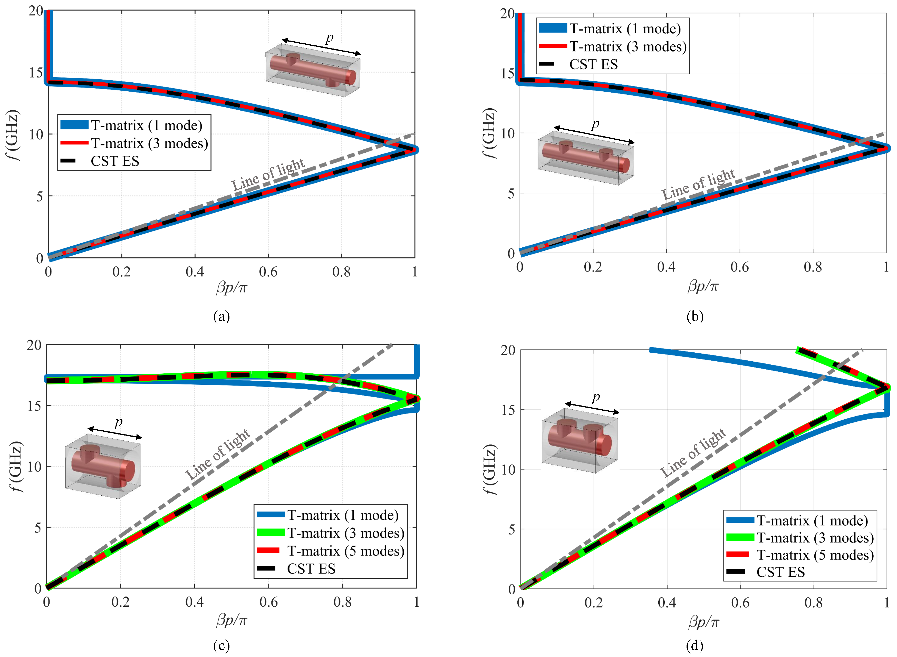
Figure 3a depicts the dispersion curves obtained with Equation (5) for the 2-fold reducible twisted cell studied in Figure 2a. It also plots the dispersion diagram obtained with a CST ES for comparison. We observe that, in this case, a monomodal T matrix (1 mode) is already enough to match the results obtained by CST ES. The results for a T matrix with 3 modes ( and in Equation (3)) also matches the monomodal T matrix and the CST ES results. This demonstrates that adding an extra set of modes does not vary the already converged results. Figure 3b shows the same results for the associated non-twisted line. Also, in this case, one single mode is sufficient to reach convergence. This confirms that in a reducible case a single mode is sufficient to accurately calculate the dispersion diagram of both the twisted and non-twisted lines.
Figure 3c depicts the dispersion diagram of the irreducible ( mm) 2-fold twisted unit cell studied in Figure 2b together with the dispersion diagram calculated with the CST ES. Here, a monomodal T-matrix method leads to the correct dispersion curve in the lower range of frequency. At higher frequencies, at least 3 modes are required. The results for 5 modes ( and ) are also sketched in the figure to further emphasize the convergence. Figure 3d shows the same results for the associated non-twisted line. In this case, one mode only is not enough even at low frequencies. This confirms that the irreducibility of a twisted line is related to the presence of coupling through higher-order modes either in the twisted line or in its associated non-twisted line. These higher-order modes interact with each other differently in the presence or absence of twists and lead to different dispersive behaviors.
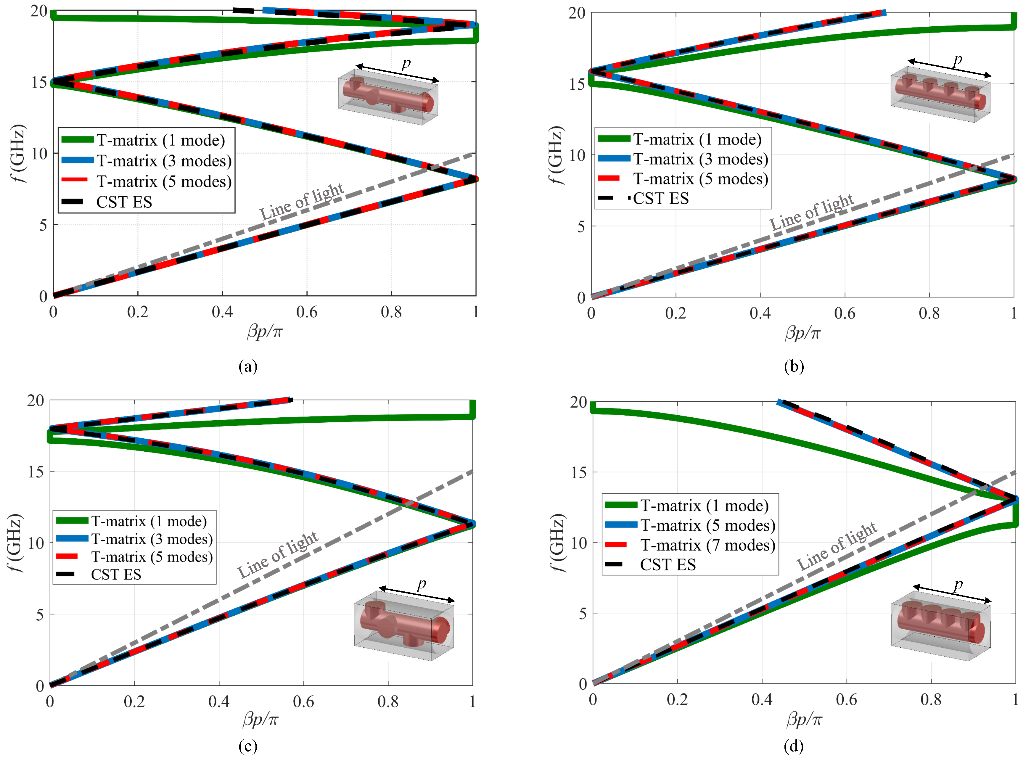
Figure 4a depicts the dispersion diagram for the 4-fold twisted cell irreducible at high frequencies studied in Figure 2c; Figure 4b shows the associated non-twisted line. Again, in the frequency ranges where the twisted line is irreducible, the presence of higher-order modes is necessary in at least one of the two lines (in this case the non-twisted line). This confirms that the difference between the lines arise from the presence of higher-order modes.
The same results are confirmed in Figure 4c,d (4-fold twisted cell irreducible over the entire frequency range): Higher-order modes are important in the non-twisted line over the entire range.
These results confirm that, while reducible structures need a single fundamental mode, irreducible structures have a more complex modal interaction: Either they or their associated non-twisted line needs a multimodal T matrix. In this specific structure, the proximity of the pins is the key parameters that makes higher-order modes relevant. The more tightly coupled the pins are, the more relevant the higher-order modes become. For instance, a reducible twisted structure in Figure 1b could become an irreducible structure by decreasing the period and increasing the size of the pins since these changes will move the pins closer to each other.
We have shown that, in this context, modelling a unit cell with a multimodal T matrix is required for accurate dispersion results. This approach is also an effective alternative to retaining multiple unit cells as in Reference [21]. Finally, we stress that this method leads to accurate results also when eigenvalue tools of commercial software are currently not available, for example, in the case of open structures, where the attenuation constant can be related to radiation (e.g., leaky waves).
3. Twist Symmetry Conditions on a Subunit Cell
In this section, we exploit the twist symmetry in order to reduce the computational domain of the periodic problem. In periodic lines, Bloch modes are eigensolutions of the translation operator , as shown in Equation (2). By virtue of the twist symmetry, Bloch modes are also eigensolutions of the twist operator [4]:
where is the relevant eigenvalue. Note that the twist operator acts here on the observation point and does not rotate the field. Since , from Equation (2), we can state that and that
where the different Nth roots merely correspond to different Floquet harmonics, so that they do not appear in Equation (7).
The new eigenvalue problem in Equation (6) with given in Equation (7) determines the Bloch modes. However, we are interested in formulating an eigenproblem for the translation operator rather than the twist operator. In fact, commercial software can easily compute a sub-cell transmission matrix, which describes the translation of fields and not the twist transformation. To overcome this problem, we first define the rotation operator:
and we express the translation operator as a composition of the symmetry operator and the inverse rotation operator :
The T-matrix formulation requires the expression of the Bloch mode as a composition of the modes of the background structure. This is a convenient basis when dealing with rotations, since each background mode in Equation (3) satisfies a simple property:
(The polarization is not stated for simplicity). If the transmission matrix of a single subunit cell of an N-fold twisted structure associated to the translation operator is , the conditions in Equations (9) and (10) lead to the following eigenvalue problem:
where is the voltage and is the current vector defined in Equation (4). The matrix can be written as
where and is the null square matrix.
Solving the generalized eigenvalue problem in Equation (11) gives the propagation constant starting from the simulation of a subunit cell of the twisted line. This formulation reduces the volume of the computational domain of the periodic problem by a factor N.
However, commercial electromagnetic software often calculates scattering parameters by means of waveguide modes with an angular dependence of the trigonometric forms or rather than the exponential form of . Therefore, a generalized eigenvalue problem based on these functions is useful for a practical implementation of the method. The radial components of the electric fields of these trigonometric modes are
where are suitable radial functions. Applying the inverse rotation operator to these electromagnetic fields gives the following (note again that the rotation is performed on the observation point, not on the vector field):
It is interesting to note that the rotation (and then also the twist condition) is no more diagonal in the trigonometric basis: Rotating one mode gives a combination of two degenerate modes, with the only exception occurring for , where only the cos term exists. This means that we have to retain both the cos and the sin modes for each .
The generalized eigenvalue in Equation (11) changes to
where the primed voltage and current vectors and are defined based on the trigonometric background modes:
The definition of the primed matrix is also given here:
Figure 5a plots the normalized phase constant of the 4-fold twist-symmetric structure shown in Figure 1b ( mm) derived from Equation (16) and compares it to the results given by CST ES. It is observed that a single mode does not provide the correct dispersion diagram at high frequencies, whereas considering 3 modes (TEM mode and the first two degenerate higher-order modes) leads to the accurate diagram, which matches the CST ES results over the entire frequency band shown. To further emphasize the advantages of the T-matrix method, the normalized attenuation constant of the structure is also given in Figure 5b where it is easy to notice that the stopband predicted with a single mode is not correct while using 3 modes correctly predicts the frequency range of first stopband. These results could not be compared to CST ES since the commercial software does not provide such information. The results with inclusion of 5 modes are also plotted in these two figures, and they match the results of the 3-mode T-matrix method. It is important to note that even though we have used the pin-loaded transmission lines in Figure 1 to verify our method, the eigenvalue problems in Equations (11) and (16) are general and they can be applied to any structure with a twist symmetry.
Furthermore, the method is also valid for a larger class of structure, characterized by the invariance under the twist transformation of Equation (1) with non-integer N. In this last case, the structure is no more periodic and, therefore, cannot be studied with available commercial software. The present approach still holds and, to the best of the authors’ knowledge, is the only formulation available for a rigorous solution of the problem.
Finally, it is interesting to compare the solving time of the T-matrix method applied to a sub-cell and the CST ES in an entire unit cell. To do so, we consider the more complex case of the 4-fold twist symmetry where 3 modes were needed in the T-matrix method. To make this comparison, we choose 76 points on the first passband and solve the problem for this frequency range. For the CST ES, an adaptive mesh refinement with a maximum of 1% relative error in frequency is defined using tetrahedral meshes. As a result, the cell is meshed with 19,850 tetrahedrons. For the CST frequency-domain solver, a relative error of 1% for scattering parameters is defined in the adaptive mesh refinement routine with tetrahedral meshes, resulting in a total of 14,310 tetrahedrons for the entire cell and 4016 tetrahedrons for the sub-cell. We have used a computer with 128 GB of RAM and an Intel(R) Xeon(R) CPU with 6 cores and a base frequency of 3.60 GHz for its CPU cores.
The computation time for these methods are included in Table 1. A quick comparison for the case of a single frequency point shows that even though the T-matrix method with a unit cell has a higher computation time compared to CST ES, the T-matrix method with the subunit cell is slightly faster than CST ES. It should be noted that a higher computation time of the unit cell formulation may be justified since the T matrix generally produces extra information on the attenuation constant of the Bloch waves and can be applied also to open structures. As we consider a large frequency range, the computation time difference changes dramatically. The T-matrix method has a shorter computation time for both the unit cell and subunit cell formulations (88 and 21 s, respectively) compared to CST ES (780 s). This occurs because the computation of the scattering parameters is accelerated significantly by the broadband sweep techniques. The rest of the computation (solving the T-matrix eigenvalue problem) is executed very fast. For instance, this part was executed in less than 2 s for 76 frequency points and 3 modes for both the unit cell and the subunit cell formulations. This is a significant reduction in computation time compared to the CST ES.
4. Conclusions
In this paper, we have discussed a transmission-matrix method for periodic structures with a higher symmetry. We have enhanced its accuracy by including higher-order modes and have demonstrated through a set of examples how the inclusion of these higher modes increases the accuracy of the method. Furthermore, we have used higher-order modes to explain how some twisted structures with symmetry can be equivalent to non-twisted structures with a reduced period. We also applied the twist operator to a transmission matrix method for the first time. This resulted in a new formulation that applies to a subregion of a unit cell for structures with a twist symmetry with a lower computation cost.
Author Contributions
Conceptualization, G.V.; methodology, M.B and G.V.; software, M.B.; validation, M.B.; formal analysis, M.B. and G.V.; writing—original draft preparation, M.B.; writing—review and editing, M.B. and G.V.; visualization, M.B.; supervision, G.V.; project administration, G.V.; funding acquisition, G.V.
Funding
This work was supported by the French governement under the ANR grant HOLeYMETA ANR JCJC 2016 ANR-16-CE24-0030 and by Sorbonne Universités under the Emergence 2016 grant MetaSym.
Acknowledgments
The authors wish to thank Francisco Mesa and Raúl Rodríguez-Berral from Universidad de Sevilla for useful discussions on the subject.
Conflicts of Interest
The authors declare no conflict of interest.
References
- Crepeau, P.J.; McIsaac, P.R. Consequences of symmetry in periodic structures. Proc. IEEE 1964, 52, 33–43. [Google Scholar] [CrossRef] [Green Version]
- Mittra, R.; Laxpati, S. Propagation in a wave guide with glide reflection symmetry. Can. J. Phys. 1965, 43, 353–372. [Google Scholar] [CrossRef]
- Kieburtz, R.; Impagliazzo, J. Multimode propagation on radiating traveling-wave structures with glide-symmetric excitation. IEEE Trans. Antennas Propag. 1970, 18, 3–7. [Google Scholar] [CrossRef]
- Hessel, A.; Chen, M.H.; Li, R.C.; Oliner, A.A. Propagation in periodically loaded waveguides with higher symmetries. Proc. IEEE 1973, 61, 183–195. [Google Scholar] [CrossRef]
- Chen, Q.; Ghasemifard, F.; Valerio, G.; Quevedo-Teruel, O. Modeling and Dispersion Analysis of Coaxial Lines with Higher Symmetries. IEEE Trans. Microw. Theory Tech. 2018, 66, 4338–4345. [Google Scholar] [CrossRef]
- Quevedo-Teruel, O.; Dahlberg, O.; Valerio, G. Propagation in waveguides with transversal twist-symmetric holey metallic plates. IEEE Microw. Wirel. Compon. Lett. 2018, 28, 858–860. [Google Scholar] [CrossRef]
- Dahlberg, O.; Mitchell-Thomas, R.C.; Quevedo-Teruel, O. Reducing the Dispersion of Periodic Structures with Twist and Polar Glide Symmetries. Sci. Rep. 2017, 7. [Google Scholar] [CrossRef] [PubMed]
- Ghasemifard, F.; Norgren, M.; Quevedo-Teruel, O. Twist and polar glide symmetries: an additional degree of freedom to control the propagation characteristics of periodic structures. Sci. Rep. 2018, 8, 11266. [Google Scholar] [CrossRef] [PubMed]
- Quesada, R.; Martín-Cano, D.; García-Vidal, F.J.; Bravo-Abad, J. Deep-subwavelength negative-index waveguiding enabled by coupled conformal surface plasmons. Opt. Lett. 2014, 39, 2990–2993. [Google Scholar] [CrossRef] [PubMed]
- Camacho, M.; Mitchell-Thomas, R.C.; Hibbins, A.P.; Sambles, J.R.; Quevedo-Teruel, O. Designer surface plasmon dispersion on a one-dimensional periodic slot metasurface with glide symmetry. Opt. Lett. 2017, 42, 3375–3378. [Google Scholar] [CrossRef] [PubMed]
- Camacho, M.; Mitchell-Thomas, R.C.; Hibbins, A.P.; Sambles, J.R.; Quevedo-Teruel, O. Mimicking glide symmetry dispersion with coupled slot metasurfaces. Appl. Phys. Lett. 2017, 111, 121603. [Google Scholar] [CrossRef]
- Palomares-Caballero, A.; Padilla, P.; Alex-Amor, A.; Valenzuela-Valdés, J.; Quevedo-Teruel, O. Twist and Glide Symmetries for Helix Antenna Design and Miniaturization. Symmetry 2019, 11, 349. [Google Scholar] [CrossRef]
- Quevedo-Teruel, O.; Ebrahimpouri, M.; Kehn, M.N.M. Ultrawideband Metasurface Lenses Based on Off-Shifted Opposite Layers. IEEE Antennas Wirel. Propag. Lett. 2016, 15, 484–487. [Google Scholar] [CrossRef]
- Ebrahimpouri, M.; Rajo-Iglesias, E.; Sipus, Z.; Quevedo-Teruel, O. Cost-Effective Gap Waveguide Technology Based on Glide-Symmetric Holey EBG Structures. IEEE Trans. Microw. Theory Tech. 2018, 66, 927–934. [Google Scholar] [CrossRef]
- Rajo-Iglesias, E.; Ebrahimpouri, M.; Quevedo-Teruel, O. Wideband Phase Shifter in Groove Gap Waveguide Technology Implemented With Glide-Symmetric Holey EBG. IEEE Microw. Wirel. Compon. Lett. 2018, 28, 476–478. [Google Scholar] [CrossRef]
- Wu, J.J.; Wu, C.J.; Hou, D.J.; Liu, K.; Yang, T.J. Propagation of Low-Frequency Spoof Surface Plasmon Polaritons in a Bilateral Cross-Metal Diaphragm Channel Waveguide in the Absence of Bandgap. IEEE Photonics J. 2015, 7, 1–8. [Google Scholar] [CrossRef]
- Ebrahimpouri, M.; Brazalez, A.A.; Manholm, L.; Quevedo-Teruel, O. Using Glide-Symmetric Holes to Reduce Leakage Between Waveguide Flanges. IEEE Microw. Wirel. Compon. Lett. 2018, 28, 473–475. [Google Scholar] [CrossRef]
- CST Microwave Studio. Version: 2019. Available online: http://www.cst.com/ (accessed on 15 March 2019).
- Pozar, D.M. Microwave Engineering, 4th ed.; John Wiley & Sons: Hoboken, NJ, USA, 2012. [Google Scholar]
- Collin, R. Field Theory of Guided Waves; Wiley-IEEE Press: Hoboken, NJ, USA, 1991. [Google Scholar]
- Valerio, G.; Paulotto, S.; Baccarelli, P.; Burghignoli, P.; Galli, A. Accurate Bloch Analysis of 1-D Periodic Lines Through the Simulation of Truncated Structures. IEEE Trans. Antennas Propag. 2011, 59, 2188–2195. [Google Scholar] [CrossRef]
Figure 1.
Pin-loaded coaxial transmission lines: (a) 2-fold twist-symmetric, (b) 4-fold twist-symmetric, (c) non-twist symmetric with 2 pins, and (d) non-twist symmetric with 4 pins. ( mm, mm, mm, and mm).
Figure 1.
Pin-loaded coaxial transmission lines: (a) 2-fold twist-symmetric, (b) 4-fold twist-symmetric, (c) non-twist symmetric with 2 pins, and (d) non-twist symmetric with 4 pins. ( mm, mm, mm, and mm).

Figure 2.
A dispersion diagram comparison of the twist-symmetric and their non-twist symmetric structures shown in Figure 1: (a) with 2 pins ( mm), (b) with 2 pins ( mm), (c) with 4 pins ( mm), and (d) with 4 pins ( mm).
Figure 2.
A dispersion diagram comparison of the twist-symmetric and their non-twist symmetric structures shown in Figure 1: (a) with 2 pins ( mm), (b) with 2 pins ( mm), (c) with 4 pins ( mm), and (d) with 4 pins ( mm).

Figure 3.
A dispersion diagram of 2-fold twist-symmetric structures in Figure 1 derived from the T-matrix method and CST ES applied to their unit cells: (a) Twisted mm, (b) associated non-twisted mm, (c) twisted mm, and (d) associated non-twisted mm.
Figure 3.
A dispersion diagram of 2-fold twist-symmetric structures in Figure 1 derived from the T-matrix method and CST ES applied to their unit cells: (a) Twisted mm, (b) associated non-twisted mm, (c) twisted mm, and (d) associated non-twisted mm.

Figure 4.
A dispersion diagram of 4-fold twist-symmetric structures in Figure 1 derived from the T-matrix method and CST ES applied to their unit cells: (a) Twisted mm, (b) associated non-twisted mm, (c) twisted mm, and (d) associated non-twisted mm.
Figure 4.
A dispersion diagram of 4-fold twist-symmetric structures in Figure 1 derived from the T-matrix method and CST ES applied to their unit cells: (a) Twisted mm, (b) associated non-twisted mm, (c) twisted mm, and (d) associated non-twisted mm.

Figure 5.
Dispersion diagrams derived with the T-matrix method on the subunit cell of the structure in Figure 1b (p = 15 mm): (a) The normalized phase constant vs. frequency and (b) the normalized attenuation constant vs. frequency ( being the free-space wavenumber).
Figure 5.
Dispersion diagrams derived with the T-matrix method on the subunit cell of the structure in Figure 1b (p = 15 mm): (a) The normalized phase constant vs. frequency and (b) the normalized attenuation constant vs. frequency ( being the free-space wavenumber).


Table 1.
The computational time for solving the periodic structure in Figure 1b.
Table 1.
The computational time for solving the periodic structure in Figure 1b.
| 1 frequency point | T matrix (subunit Cell) | T matrix (unit cell) | CST (eigensolver) |
| Time (s) | 12 | 19 | 13 |
| 76 frequency points | T matrix (subunit cell) | T matrix (unit cell) | CST (eigensolver) |
| Time (s) | 21 | 88 | 780 |
© 2019 by the authors. Licensee MDPI, Basel, Switzerland. This article is an open access article distributed under the terms and conditions of the Creative Commons Attribution (CC BY) license (http://creativecommons.org/licenses/by/4.0/).
Share and Cite
MDPI and ACS Style
Bagheriasl, M.; Valerio, G. Bloch Analysis of Electromagnetic Waves in Twist-Symmetric Lines. Symmetry 2019, 11, 620. https://doi.org/10.3390/sym11050620
AMA Style
Bagheriasl M, Valerio G. Bloch Analysis of Electromagnetic Waves in Twist-Symmetric Lines. Symmetry. 2019; 11(5):620. https://doi.org/10.3390/sym11050620
Chicago/Turabian StyleBagheriasl, Mohammad, and Guido Valerio. 2019. "Bloch Analysis of Electromagnetic Waves in Twist-Symmetric Lines" Symmetry 11, no. 5: 620. https://doi.org/10.3390/sym11050620
Note that from the first issue of 2016, this journal uses article numbers instead of page numbers. See further details here.