A Survey of Methods for Symmetry Detection on 3D High Point Density Models in Biomedicine


Department of Industrial Engineering, University of Florence, 50139 Florence, Italy
*
Author to whom correspondence should be addressed.
Symmetry 2018, 10(7), 263; https://doi.org/10.3390/sym10070263
Submission received: 4 May 2018
/
Revised: 28 June 2018
/
Accepted: 4 July 2018
/
Published: 4 July 2018
Abstract
:Versatile, cheap and non-invasive 3D acquisition techniques have received attention and interest in the field of biomedicine in recent years as the accuracy of developed devices permits the acquisition of human body shapes in detail. Interest in these technologies derives from the fact that they have the potential to overcome some limitations of invasive techniques (CT, X-rays, etc.) and those based on 2D photographs for the acquisition of 3D geometry. However, the data acquired from the 3D scanner cannot be directly used but need to be processed as they consist of 3D coordinates of the acquired points. Therefore, many researchers have proposed different algorithms which recognise the shape of human body and/or its features when starting from a 3D point cloud. Among all possible human body features to be evaluated, symmetry results the most relevant one. Accordingly, this survey systematically investigates the methods proposed in the literature to recognise 2D symmetry by the symmetry line and bilateral symmetry by the symmetry plane. The paper also analyses qualitative comparisons among the proposed methods to provide a guide for both practitioners and researchers.
1. Introduction
Human perception as well as the sense of aesthetics are mainly related to the recognition of symmetrical patterns [1,2,3,4]. Moreover, numerous objects around us, such as many man-made (i.e., aeroplanes and houses) and natural (i.e., insects and molecules) objects, are mainly symmetric.
Recently, several works related to symmetry analysis and symmetry-aware shape processing of point clouds have been introduced in computer graphics, where the existing works deal with both extrinsic symmetry detection over complete shapes [5] and on intrinsic symmetry, defined as a region over a shape that possesses a self-map that preserves geodesic distances [6]. A survey of most relevant methods to find, encode and exploit geometric symmetries is provided in [7]. Some innovative recent works in this field are the one proposed by Bokeloh et al. [8], where rigid symmetries are computed by matching locally coherent constellations of feature lines on the object surfaces, and by Ovsjanikov et al. [9], which devise an algorithm able to detect and compute the isometric mappings from the shape onto itself.
The noticeable interest in this topic led to study symmetry also in the field of biomedicine. In fact, many applications, such as in the biomedical and orthopaedic fields, symmetry plays a particular role in the detection of diseases and in the identification of anthrpometric conditions.
Indeed, although the detection of symmetry is relatively easy for the human eye, a challenge in the engineering field relates to computational difficulties frequently encountered in the identification of symmetry for biological structures.
Most of the work that leads to computer vision encompass the investigation of 2D symmetries more willingly than 3D symmetries. This is mainly due to the fact that image acquisition is a pervasive application able to efficiently handle 2D data in terms of efficiency and computational time. Moreover, the recent progresses in Reverse Engineering (RE) and in 3D scanning lead to an increasingly effective analysis of 3D geometry thus allowing the identification of symmetry in studying biological 3D data [1]. Consequently, a number of symmetry-analysis algorithms have been proposed in recent years, mainly categorised in two groups: feature-based or intensity-based methods. When referring to feature-based methods, the symmetry analysis starts from 2D or 3D point clouds or meshes (graphs).
Since a large number of approaches aiming to find symmetry in human body and/or its features have been presented in literature, the present work aims to systematically investigate the methods proposed in the literature to recognise 2D/3D symmetry by the symmetry line and bilateral symmetry by the symmetry plane. In detail, this paper considers the methods that analyse real meshes (i.e., meshes representing real-world objects). Furthermore, the paper also classifies the surveyed methods based on the dimension of the geometric primitive with respect to which the symmetry is evaluated. The following symmetries are considered:
- -
- 2D symmetry: symmetry line
- -
- 3D symmetry: symmetry plane
The methods that provide a substantial mathematical dissertation have been referred directly to the original works.
2. Symmetry Line
The identification of the 3D curve passing through the external position of the vertebral apophyses is among one of the most relevant applications of symmetry line theory, applied to the model of the back. Moreover, once the symmetry line is known and the thickness of the soft parts is taken into account, the spinal midline can be easily estimated, according to [10]. In subjects with no afflictions, the symmetry line is the one that divides the back into two “quasi mirror-image” parts each one describing the involuntary orthogonal transformation of the other [11]. Kyphosis, scoliosis or lordosis can arise during adolescence and cause either the deviation of the spine from the sagittal plane or even torsions.
Determination of the symmetry line is often a challenge to overcome both due to the need of a not trivial elaboration of the acquired point cloud and the acquisition of the back’s shape properties. All methods devoted to the identification of the symmetry line are discussed in the following paragraphs and consist of using a 3D scanner on the overall surface of the subject’s back. These methods can be classified into three categories:
- -
- Cutaneous marking-based methods
- -
- Parallel sections-based methods
- -
- Adaptive sections-based methods
2.1. Cutaneous Marking-Based Methods
Turner and Smith [12] introduced the earliest approach for determining the symmetry line starting from the 3D acquisition of the back. Their method consisted of acquiring the 3D position of landmarks on the vertebrae prominences by manual palpation and had an accuracy of landmark positioning that was estimated to be 5 mm. The broken line that joins the barycentre of each marker defines the symmetry line.
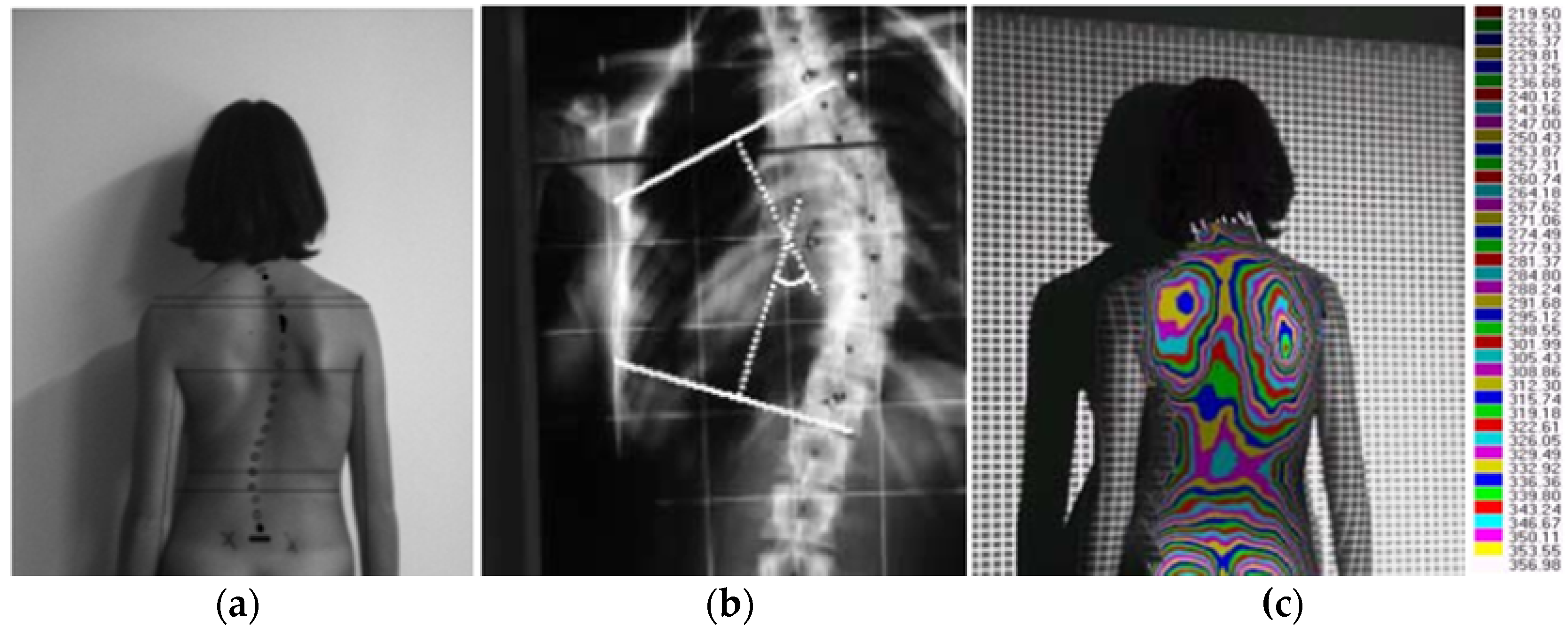
After this first study, in [13] a relationship between information from a structured light 3D scanner and traditional X-ray images is proposed. Their method consisted of building a back-surface depth map for a set of reference nodes for calibration purposes, while the remainder of points on the back surface were reconstructed by means of a parametric approximation. To obtain the curve of the spine, cutaneous markers were initially positioned on the back surface corresponding to vertebral spinous processes from C7 to the last lumbar vertebra L5 (Figure 1a), with approximately the same accuracy as the Turner–Smith method. The X-ray images, opportunely scaled, rotated and translated (see Figure 1b) were subsequently projected on the topographic representation of the back surface (Figure 1c).
To construct a 3D parametric representation of the symmetry line, the authors approximated the acquired locations of the markers using a polynomial curve C(u):
where nx and nz are the degrees of the polynomials, and and are the coefficients of the polynomials (computed using the least squares method). Based on a sample of 76 patients, a high correlation was obtained between the results from both techniques (r = 0.89). The main limitation of the methods introduced by Turner and Smith and Sotoca et al. was that the markers, identified with apophyses, must be manually identified.
2.2. Parallel Sections-Based Methods
The first methodology based on parallel sections is reported in [10]. A global reference system was related with the subject’s back; in such a system, the vertical axis Z was defined by the line joining the sacrum with the prominence of the seventh cervical vertebra. The back surface was then sliced by a set of planes normal to Z so that to define a set of slice curves. For each curve, the so-called “lateral asymmetry function” was defined as described below.
Let p be a generic point belonging to a given slice curve, and L0 be a reference length defined by the measure of the radius of p neighbourhood. The length of reference value, L0, is crucial for evaluating the symmetry, especially if compared with the dimensions of the symmetrical portion of the back. Variation in the assignment of L0 leads to different symmetry index values, as it checks symmetry in a narrower or wider range of the investigated zone. The single point asymmetry contribution a(u) is evaluated at the points of each slice symmetrically positioned to the left (subindex l) and right (subindex r) of the considered point p:
where H is the mean curvature, Hl is H(ξ − u), Hr is H(ξ + u), G is Gaussian curvature, Gl is G(ξ − u), Gr is G(ξ + u), ξ is the curvilinear abscissa of point p and is the difference between the angular orientation of the principal direction in l and r (k1,l and k1,r).
The lateral curvature asymmetry A, with respect to p, is defined as:
The function A(p, L0) has a value of zero for curve points that have a perfectly specular neighbourhood. The minimum value of A(p, L0) identifies the position of the spine i.e., the point best representing the curve symmetry.
Huysmans et al. [14] proposed optimising the lateral asymmetry function by other factors including blending, torsions, curvatures and biomechanical constraints. Hence the symmetry line can be detected by minimizing the following cost function ():
where the i index refers to the single slice curve, and αi and βi are the weight factors for the different cost terms. The authors compared their method with the one proposed in [4] by applying it to the analysis of 33 patients with scoliosis, and the results were similarly accurate between the two methods. However, Huysmans et al. affirmed that their method was advantageous as it could be applied to several postures and biomechanical constraints taking into account information coming from previous measurements. Furthermore, due to the global optimization, the location of anatomical landmarks was more robust and reliable. Conversely, one drawback of this method was the need to evaluate six coefficients (α1, α2, β1, β2, β3, β4) to become accustomed to the study of average individuals.
In the approach proposed in [15], the local shape of the back surface (see Figure 2) is defined by analysing the directions of principal curvatures.
Assuming the surface oriented with approximately vertical backbone orientation, the most horizontal principal direction was used. The profile for the generic jth cutting plane was then defined as the set of centroids {PC1j, PC2j, …, PCmj} of the points near to the cutting plane and projected on it and the set of profile directions {v1j, v2j, …, vmj}. For each profile j, the following function was considered:
where is the slope angle of and G is the derivative Gaussian function. According to Equation (5), PCkj is a concave region in case g() > 0; quite the reverse it is a convex region if g() < 0. The point that located the symmetry line in the jth cutting plane was obtained by using a symmetric position criterion applied to function .
In [10] a novel symmetry index based on symmetry “analysis in the orientation of the normal unit vectors of horizontal sections of the back surface” is introduced (see Figure 2):
where L0 is the reference length and where:
with
- -
- ;
- -
- .
where n(ν + u) and n(ν − u) are normal unit vectors evaluated at points p(ν + u) and p(ν − u) of the horizontal section. These lie symmetrically with respect to point p(ν). The symmetric point of the ith slice profile (Γi) was the one with the minimum symmetry index value. Figure 3 illustrates all the characteristic elements of .
The symmetrical points obtained for n horizontal sections were approximated using the parametric curve C(t) = {x(t), y(t), z(t)} defined as follows:
Coefficients ai, bi and ci were calculated using a weighted least squares method. The position of the symmetrical points was associated with relative and not absolute maximum values of , therefore the method opportunely estimates the symmetry line.
To quantify the performance of their method, Di Angelo et al. [16] proposed a comparison with the method of Drerup and Hierholzer [10] by analysing the standing and sitting postures of 75 subjects (male and female university students aged 20–22). The detected symmetry line was also compared with a traditional identification method based on cutaneous marking. The two methods proved to have a comparable level of accuracy; however, in more detail, the method proposed in [10] showed lower errors when estimating the symmetry line for the lumbar and thoracic tracts, whereas some issues arised when estimating the symmetry line in the cervical tract. The method of Drerup and Hierholzer [10] required thousands of instances to be investigated to select the most promising set of points, thus resulting less computational efficient. Quite the reverse, the method proposed in [16] required only few instances (at most, hundreds of instances).
The abovementioned methods, which are mainly based on horizontal slicing, are explicitly suited to detect the symmetry line for erect postures; however, they do not provide reliable results when dealing with postures characterized by spine configurations lying outside the sagittal plane (e.g., unspecific posture with trunk torsion).
2.3. Adaptive Sections-Based Methods
To overcome the restrictions of horizontal slicing methods and allow the analysis of asymmetric postures that are widely assumed by workers in their workplaces, Di Angelo et al. [17,18] proposed a new method, called “nonerected posture approach (NEPA)”, relying on an adaptive approach.
In detail a local reference system associated to the Frenet–Serret frame of the symmetry line {OL(t), ξL(t), ψL(t), ζL(t)} is introduced (see Figure 4). OL(t) is a point of the symmetry line, ζL(t) is the tangent in OL(t), ψL(t) is the symmetry line perpendicular to OL(t) and ξL(t) is normal to ζL(t) and ψL(t).
The method used a first-attempt symmetry line (C0) defined according to the method proposed in [16], which was subsequently refined by the algorithm shown in Figure 5. The NEPA method identifies the set of planes [Π(t)] which define onto the back surface a set of profiles [Γ(t)] that exhibit the maximum possible symmetry according to the expression in Equation (6). The NEPA method converges if Π(t) sections the back in the most symmetrical profiles and if the symmetry line passes through the most symmetrical points of the back.
With the aim of validating the method, four specific asymmetric postures were analysed in 20 subjects. The NEPA method was compared with the symmetry line detection method presented in [16], which had cutaneous marking as a common reference. The results showed that NEPA improved the symmetry line detection estimation efficacy by approximately 6–7%. Figure 6 provides an example of the results offered using this method.
By analysing the NEPA method and the experimentation presented by the authors, it is evident that this iterative method is strongly affected by the initial symmetry line. To overcome this limitation, a different approach to identifying the final symmetry line configuration was proposed in [19]. This new method analysed the profiles given by the intersection of the back surface using a set of planes (Πk) orthogonal to the direction identified by the previous pair of symmetry points (each point being at a given distance or ‘step’ from the previous and following points as demonstrated in Figure 7).
This method was validated by analysing the same asymmetric postures reported in [17] in 70 subjects. The results showed that the new method correctly evaluated the symmetry line, even in the case of extreme asymmetric postures, providing an error decreasing equal to approximately 20% when referred to the initial estimation. Though referred to a seated posture, obtained results confirm the applicability of the proposed method in dealing with any other asymmetric posture characterized by the same critical aspects. Figure 8 compares results obtained by using the traditional approach against the refinement-based methods described above.
3. Symmetry Plane
One of the most relevant geometric features of a real object consists of the plane that identifies the object’s bilateral symmetry. Such a plane can be recognised by properly process 3D data obtained, for instance, using 3D scanners. However, in practice, data obtained using 3D scanners are often incomplete and even not symmetrically acquired. This is because traditional technologies used in 3D acquisition require the model to be completely detectable from the device viewpoint. The most important methods available in literature dealing with symmetry plane detection are:
- Extended Gaussian image (EGI)
- Mirroring and registration
3.1. Adaptive Sections-Based Methods
As widely known [20], the EGI of a polyhedron is a Gaussian map where the planar triangular facets normal direction is weighted by the relative extension area. Consequently, EGI-based methods for 3D symmetry detection mostly assume that if an object is recognized as symmetrical, then EGI can be considered [20]. The first EGI-based approach for determining the symmetry plane of a given solid was proposed by Sun and Sherrah [14]. They analysed the so called “recurrence histogram of the orientation of normal unit vectors from EGI”. To reduce the computational costs, the EGI map around the principal axes of inertia of the orientation histogram (see Figure 9) was used.
Pan et al. [21] aimed to identify a solution to improve the robustness of the method for noisy data. This consisted on using the inverse of the Gaussian curvature for computing the orientation histogram. The robustness of the method was increased by evaluating the Gaussian curvature using a paraboloid fitting. Taking into account an average value from a larger neighbourhood (when compared with the one explored by discrete methods) Pan’s approach was able to estimate the differential geometric properties [22]. It is important to highlight that the EGI-based methods do not analyse the geometry symmetry therefore the obtainable results depend on the symmetry of the 3D acquisition.
3.2. Adaptive Sections-Based Methods
The mirroring and registration methods detect the symmetry plane of an object directly by evaluating the overlap of the point cluod describing the 3D object with its mirroring. To this end, they typically roughly estimate the symmetry plane (Π0) and then mirror the original data PC with respect to Π0, thus defining a set of mirrored points PCm. PC and PCm are then registered by using the iterative closest point (ICP) algorithm [23]. The result is a registered point cloud PCm,r. The final estimation of the symmetry plane (Πf) is obtained as the least-square approximating plane through the middle points of the segments joining homologous points in PC and PCm,r. Many of the methods in the literature deal with symmetry plane retrieval of faces.
Benz et al. [24] were the pioneers of the application of the mirroring method in aesthetic surgical facial reconstruction. The symmetry plane was adopted to mirror the healthy half of the face onto the damaged half to reconstruct the latter (Figure 10). The authors stressed that it was sufficient to choose healthy areas in a damaged face (i.e., chin, nose and forehead) to register both the scanned data and the mirrored ones, using an appositely modified ICP algorithm [25].
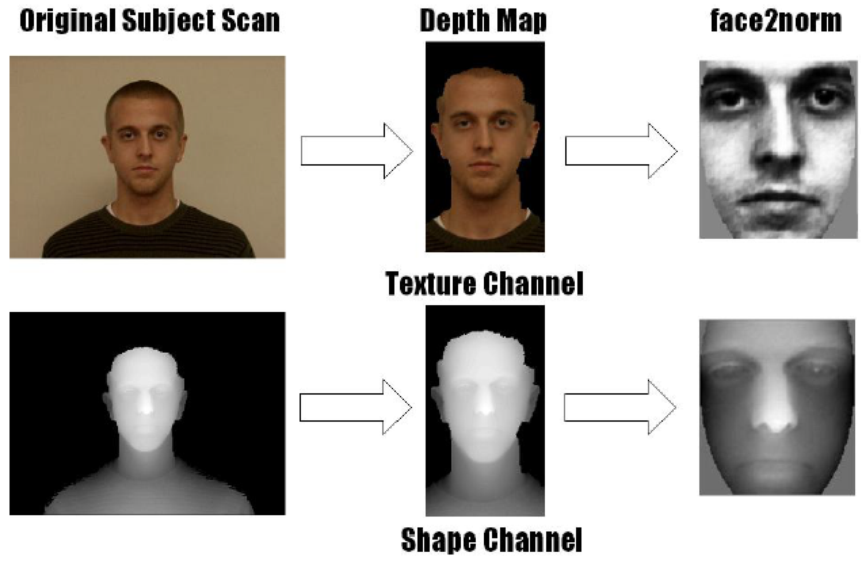
De Momi et al. [26] proposed a variation of the previous approach. They performed a rough estimation of the symmetry plane starting from centroids of areas that were manually chosen on the 3D model. Starting from this approach, and with the aim of developing a fully automatic method, Colbry and Stockman [27] proposed an approach that evaluated the first-attempt symmetry plane using a method based on the Face Recognition Grand Challenge (FRGC) principal component analysis (PCA) algorithm [28] (Figure 11).
As highlighted by Tang et al. [29], this approach has a high probability of failing if the input data are asymmetrically scanned. In these instances, the inaccuracy of the PCA method in calculating the symmetry plane commonly leads to a nonconvergent ICP registration algorithm. To solve this issue, Tang et al. suggested choosing a symmetry plane passing through the centroid of the face and parallel to the coordinate system yz plane [29]. This approach is viable only in case the actual symmetry plane is approximately aligned with the yz plane of the scanning device. To render the ICP registration unaffected by the presence of asymmetrical data, authors in [29] analysed a symmetric rectangular region selected around the nose (see Figure 12 and Figure 13). This can only be considered as a valid approach in cases with undistorted noses.
Zhang et al. [30] demonstrated that the ICP algorithm cannot be able to perform a correct registration in case the face boundary presents several irregularities. Consequently, they proposed to use the so called “MarkSkirt operator”, i.e., a procedure which discards from registration procedure the points belonging to the outer 10 rings of the model boundary (see Figure 14).
Combès et al. recently presented a method able to directly estimate the symmetry plane without the need of intermediate pre-processing methods involving roto-translation and registration [31,32,33,34]. Even if theinitial estimation of the symmetry plane is carried out by employing the PCA method, its final evaluation (i.e., plane Πf) was assessed by using an iterative procedure aiming at determining the minimum of a properly build objective function (given by the sum of the weighted distances between the points reflected with respect to Πf and the corresponding nearest points of the cloud). Wights were expressed as the Leclerc function [35] to avoid the presence of an asymmetrically sampled area. However, the procedure appeared to still be sensitive to sampling inconsistency. Two perfectly symmetrical homologous surfaces characterised by different sampling densities turned out to be asymmetrical exclusively due to the distance between the originally acquired point cloud and the mirrored one.
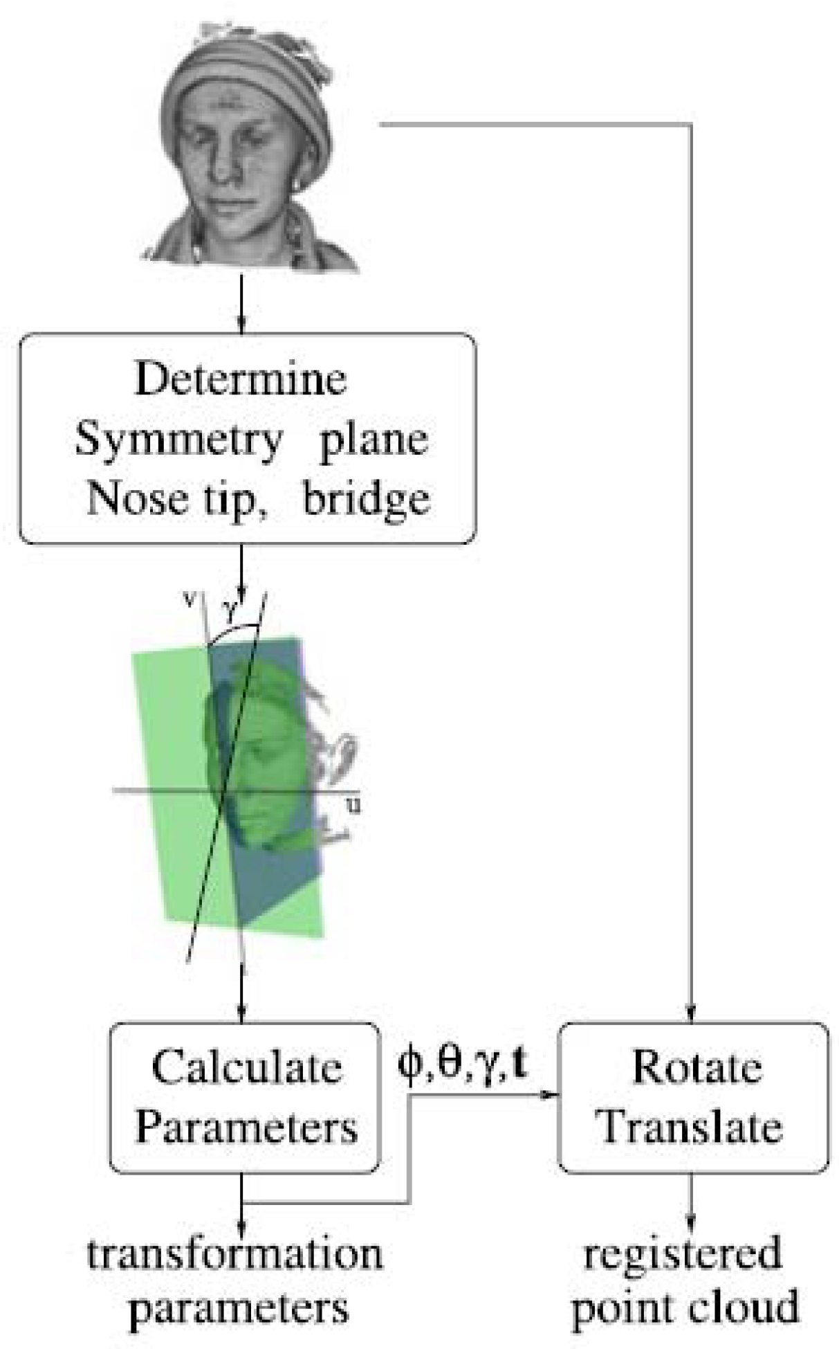
It has to be noticed that ICP algorithms are computationally expensive. Therefore, a number of attempts to speed them up are in literature [31,32,33,34]. Other methods, such as the mirroring and registration method proposed by Spreeuwers [36], are not based on ICP (see Figure 15). The symmetry plane is estimated through subsequent attempts to vary the identification parameters (i.e., dx: the x coordinate of the intersection of the symmetry plane with the x-axis, ϑ: rotation around the y-axis; φ: rotation around the z-axis) by the user who chooses the range and steps. The procedure ends when the minimum value of the distance between the corresponding points of the cloud and the mirrored one is found. This method is computationally more efficient when compared with the ICP algorithm even though it does not address the aforementioned issues (see below).
All of the analysed methods are sensitive to data asymmetries that result from the acquisition process. As already mentioned in Introduction, in a 3D scanning process the density of point sampling is heavily influenced by the surface orientation with respect to the observation direction [30]. When surfaces are orthogonally oriented with respect to the view direction, points density is higher than when views are foreshortened. The consequence is that even for highly symmetric objects the different point density may lead to non-symmetrical point clouds (i.e., the object is mapped by not symmetrical points). Furthermore, due to the orientation of the object with respect to the observation view, the parts that remain hidden are not acquired. Another issue is related to the possible presence of irregularities in the borders of the surface. Di Angelo et al. proposed a method to overcome these limitations [11,37]. In such a method, the initial estimation of the symmetry plane was achieved by using the PCA method while the final solution was obtained by minimising a properly-weighted Hausdorff distance, which is one of the key aspects of the proposed method. The Hausdorff distance was calculated between points of the acquired cloud and the tessellated surface of the same points, once these are reflected with respect to Πf. The two weights used, expressed as Leclerc function, consider the distance of points from the symmetry plane and local asymmetries. The authors showed that their method was insensitive to non-uniformity in point cloud density as well as to asymmetrically mapped data.
4. Conclusions
This review aims to determine current state-of-the-art methods to recognise the symmetry of human body shapes. Preliminary analysis of the literature showed that the most important methods recognise symmetry with respect to a line (2D symmetry) and a plane (3D symmetry). This paper focused on two areas in which the greatest efforts were spent: 2D symmetry recognition of the human back and 3D symmetry recognition of the human face.
The main considerations related to this state of the art analysis are summarised in Table 1 and Table 2 to disseminate the acquired information to a wider field of researchers. The tables report, distinguishing between methods for the recognition of 2D (Table 1) and 3D symmetry (Table 2), the category, in accordance with the proposed classification, the summary description, advantages and limitations for each method. Where available, some performance indicators are also listed. Therefore, the reported results are easy to consult when choosing the best method to estimate the two types of symmetries, even for areas other than those analysed.
Based on the state of the art analysis carried out in the present work, it is possible to draft some practical considerations to guide potential users and/or researchers on the correct choice of most suitable algorithms to detect symmetry when processing biomedical data.
In case the main intent is to detect a symmetry line, it has to be considered that almost all referred methods share the same kind of acquisition device consisting on a structured light scanner (e.g. body scanners [1], video raster stereography [38], low-cost RGB-D cameras [39]). Cutaneous marking-based methods makes exception since they require also the availability of X-ray images to aid the manual selection of relevant points on the back of the patient. Consequently, parallel sections-based methods have to be preferred for two reasons: 1) data processed to detect symmetry line are obtained using optical devices and 2) the selection of slices is performed automatically (i.e. without the need of manually select relevant points on the back of the patient). The main drawback, however, is related to the computational time for determining the symmetry line, mostly depending on the number of slices used to partition the 3D data. To enforce the symmetry line detection and, at the same time, to reduce the computational time, adaptive sections-based methods presented in [18,19] can be the best solution.
In case the symmetry plane estimation is the main aim of the research, it has to be highlighted that all referred methods are based on the availability of 3D point clouds, with the exception of EGI based methods. This last class of methods, in fact, processes only synthetic 3D images; consequently, their reliability for real scanned 3D data has not been fully explored in literature. For this reason, symmetry plane can be better estimated using mirroring and registration methods which analyse the overlap of the point cloud describing the 3D object with its mirroring. The main drawback of this class of methods is the computation time since many of them use the ICP algorithm [31]. Moreover, they are sensitive to data asymmetries that result from the acquisition process. To overcome the first issue, the algorithms proposed in [35] have to be preferred. When dealing with the second issue, algorithms proposed in [11,37] represent the best choice since they reduce the sensitivity to both asymmetrically 3D data and non-uniformity in terms of point cloud density.
Author Contributions
C.B. carried out the bibliographical research together with Y.V., R.F. and L.G. organized the systematic review. All authors contributed to write the paper.
Funding
This research received no external funding.
Conflicts of Interest
The authors declare no conflict of interest.
References
- Furferi, R.; Governi, L.; Uccheddu, M.F.; Volpe, Y. A RGB-D based instant body-scanning solution for compact box installation. Adv. Mech. Des. Eng. Manuf. 2017, 387–396. [Google Scholar] [CrossRef]
- Fatuzzo, G.; Sequenzia, G.; Oliveri, S.M. Virtual anthropology and rapid prototyping: A study of Vincenzo Bellini’s death masks in relation to autopsy documentation. Digit. Appl. Archaeol. Cult. Herit. 2016, 3, 117–125. [Google Scholar] [CrossRef]
- Thompson, D.W. On Growth and Form; Cambridge University Press: Cambridge, UK, 1942. [Google Scholar]
- Martinet, A.; Soler, C.; Holzschuch, N.; Sillion, F.X. Accurate detection of symmetries in 3D shapes. ACM Trans. Graph. Assoc. Comput. Mach. 2006, 25, 439–464. [Google Scholar] [CrossRef] [Green Version]
- Mitra, N.J.; Pauly, M.; Wand, M.; Ceylan, D. Symmetry in 3D Geometry: Extraction and Applications. In Eurographics State-of-the-Art Report; The Eurographics Association: London, UK, 2012; pp. 1–23. [Google Scholar]
- Jiang, W.; Xu, K.; Cheng, Z.Q.; Zhang, H. Skeleton-based intrinsic symmetry detection on point clouds. Graph. Models 2013, 75, 177–188. [Google Scholar] [CrossRef]
- Mitra, N.J.; Pauly, M.; Wand, M.; Ceylan, D. Symmetry in 3D geometry: Extraction and applications. Comput. Graph. Forum 2013, 32, 1–23. [Google Scholar] [CrossRef]
- Bokeloh, M.; Berner, A.; Wand, M.; Seidel, H.-P. Andreas schilling: Symmetry detection using feature lines. Comput. Graph. Forum 2009, 28, 697–706. [Google Scholar] [CrossRef]
- Ovsjanikov, M.; Sun, J.; Guibas, L. Global Intrinsic Symmetries of Shapes. Comput. Graph. Forum 2008, 27, 1341–1348. [Google Scholar] [CrossRef] [Green Version]
- Drerup, B.; Hierholzer, E. Back shape measurement using video rasterstereography and 3-dimensional reconstruction of spinal shape. Clin. Biomech. 1994, 9, 28–36. [Google Scholar] [CrossRef]
- Di Angelo, L.; Di Stefano, P. A computational method for bilateral symmetry recognition in asymmetrically scanned human faces. Comput. Aided Des. Appl. 2014, 1, 275–283. [Google Scholar] [CrossRef]
- Turner-Smith, A.R.; Harris, J.D.; Houghton, G.R.; Jefferson, R.J. A method for analysis of back shape in scoliosis. J. Biomech. 1988, 21, 497–509. [Google Scholar] [CrossRef]
- Sotoca, J.M.; Buendia, M.; Inesta, J.M.; Ferri, F.J. Geometric properties of the 3D spine curve. Lect. Notes Comput. Sci. 2003, 2652, 1003–1011. [Google Scholar]
- Huysmans, T.; Haex, B.; Van Audekercke, R.; Vander Sloten, J.; Van der Perre, G. Three-dimensional mathematical reconstruction of the spinal shape based on active contours. J. Biomech. 2004, 7, 1793–1798. [Google Scholar] [CrossRef] [PubMed]
- Santiesteban, Y.; Sanchez, J.M.; Sotoca, J.M. A method for detection and modelling of the human spine based on principal curvature. Prog. Pattern Recognit. Image Anal. Appl. 2006, 168–177. [Google Scholar] [CrossRef]
- Di Angelo, L.; Di Stefano, P.; Vinciguerra, M.G. Experimental validation of a new method for symmetry line detection. Comput. Aided Des. Appl. 2011, 8, 71–86. [Google Scholar] [CrossRef]
- Di Angelo, L.; Di Stefano, P.; Spezzaneve, A. An iterative method to detect symmetry line falling far outside the sagittal plane. Int. J. Interact. Des. Manuf. 2012, 4, 233–240. [Google Scholar] [CrossRef]
- Di Angelo, L.; Di Stefano, P.; Spezzaneve, A. Symmetry line detection for non-erected postures. Int. J. Interact. Des. Manuf. 2013, 7, 271–276. [Google Scholar] [CrossRef]
- Di Angelo, L.; Di Stefano, P.; Spezzaneve, A. A method for 3D symmetry line detection in asymmetric postures. Comput. Methods Biomech. Biomed. Eng. 2013, 16, 1213–1220. [Google Scholar] [CrossRef] [PubMed]
- Sun, C.; Sherrah, J. 3D symmetry detection using the extended Gaussian image. IEEE Trans. Pattern Anal. Mach. Intell. 1997, 19, 164–168. [Google Scholar] [CrossRef] [Green Version]
- Pan, G.; Wang, Y.; Qi, Y.; Wu, Z. Finding symmetry plane of 3D face shape. In Proceedings of the International Conference on Pattern Recognition, Hong Kong, China, 20–24 August 2006; pp. 1143–1146. [Google Scholar]
- Ikemitsu, H.; Zeze, R.; Yuasa, K.; Izumi, K. The relationship between jaw deformity and scoliosis. Oral Radiol. 2006, 22, 14–17. [Google Scholar] [CrossRef]
- Besl, P.J.; McKay, N.D. A method for registration of 3D shapes. IEEE Trans. Pattern Anal. Mach. Intell. 1992, 14, 239–256. [Google Scholar] [CrossRef]
- Benz, M.; Laboureu, X.; Maier, T.; Nkenke, E.; Seeger, S.; Neukam, F.W.; Häusler, G. The symmetry of faces. In Proceedings of the Vision, Modeling, and Visualization Conference 2002 (VMV 2002), Erlangen, Germany, 20–22 November 2002. [Google Scholar]
- Seeger, S.; Laboureux, X.; Häusler, G. An accelerated ICP algorithm. In Lehrstuhl für Optik; Annual Report; Friedrich-Alexander-Universität: Erlangen, Germany, 2001. [Google Scholar]
- De Momi, E.; Chapuis, J.; Pappas, I.; Ferrigno, G.; Hallermann, W.; Schramm, A.; Caversaccio, M. Automatic extraction of the mid-facial plane for craniomaxillofacial surgery planning. Int. J. Maxillofac. Surg. 2006, 35, 636–642. [Google Scholar] [CrossRef] [PubMed]
- Colbry, D.; Stockman, G. Canonical face depth map: A robust 3D representation for face verification. In Proceedings of the 2007 IEEE Computer Society Conference on Computer Vision and Pattern Recognition (CVPR’07), Minneapolis, MN, USA, 17–22 June 2007; pp. 1–7. [Google Scholar]
- Pearson, K. On lines and planes of closest fit to systems of points in space. Phil. Mag. 1901, 2, 559–572. [Google Scholar] [CrossRef]
- Tang, X.M.; Chen, J.S.; Moon, Y.S. Accurate 3D face registration based on the symmetry plane analysis on nose regions. In Proceedings of the 16th European Signal Processing Conference (EUSIPCO), Lausanne, Switzerland, 25–29 August 2008. [Google Scholar]
- Zhang, L.; Razdan, A.; Farin, G.; Bae, M.S.; Femiani, J. 3D face authentication and recognition based in bilateral symmetry analysis. J. Vis. Comput. 2006, 22, 43–55. [Google Scholar] [CrossRef]
- Combès, B.; Hennessy, R.; Waddington, J.; Roberts, N.; Prima, S. An algorithm to map asymmetries of bilateral objects in point clouds. In Proceedings of the International Symposium on Biomedical Imaging: From Nano to Macro, Paris, France, 14–17 May 2008. [Google Scholar]
- Combès, B.; Hennessy, R.; Waddington, J.; Roberts, N.; Prima, S. Automatic symmetry plane estimation of bilateral objects in point clouds. In Proceedings of the International Conference on Computer Vision and Pattern Recognition, Anchorage, ANC, USA, 23–28 June 2008. [Google Scholar]
- Combès, B.; Prima, S. New algorithms to map asymmetries of 3D surfaces. In Proceedings of the International Conference on Medical Image Computing and Computer Assisted Intervention, New York, NY, USA, 6–10 September 2008. [Google Scholar]
- Black, M.J.; Rangarajan, A. On the unification of line processes, outlier rejection, and robust statistics. Int. J. Comput. Vis. 1996, 19, 57–91. [Google Scholar] [CrossRef]
- Spreeuwers, L. Fast and accurate 3D face recognition. Int. J. Comput. Vis. 2011, 93, 389–414. [Google Scholar] [CrossRef]
- Barone, S.; Paoli, A.; Razionale, A.V. A coded structured light system based on primary color stripe projection and monochrome imaging. Sensors 2013, 13, 13802–13819. [Google Scholar] [CrossRef] [PubMed]
- Di Angelo, L.; Di Stefano, P. Bilateral symmetry estimation of human face. Int. J. Interact. Des. Manuf. 2013, 7, 217–225. [Google Scholar] [CrossRef]
- Carfagni, M.; Furferi, R.; Governi, L.; Servi, M.; Uccheddu, F.; Volpe, Y. On the performance of the intel SR300 depth camera: Metrological and critical characterization. IEEE Sens. J. 2017, 17, 4508–4519. [Google Scholar] [CrossRef]
- Weiss, H.R.; Elobeidi, N. Comparison of the kyphosis angle evaluated by video rasterstereography (VRS) with x-ray measurements. Stud. Health Technol. Inform. 2008, 140, 137–139. [Google Scholar] [PubMed]
Figure 1.
Clinical image of a patient affected by a severe thoracic scoliosis. (a) The vertebral spinous processes are marked on the skin. (b) A radiograph image from the patient. (c) Topographic representation of the back surface [7].
Figure 1.
Clinical image of a patient affected by a severe thoracic scoliosis. (a) The vertebral spinous processes are marked on the skin. (b) A radiograph image from the patient. (c) Topographic representation of the back surface [7].

Figure 2.
Horizontal cutting planes defining profiles (a), cutting plane example for j = 2 (b) [9].
Figure 2.
Horizontal cutting planes defining profiles (a), cutting plane example for j = 2 (b) [9].

Figure 3.
Definition of the symmetry index [10].
Figure 3.
Definition of the symmetry index [10].
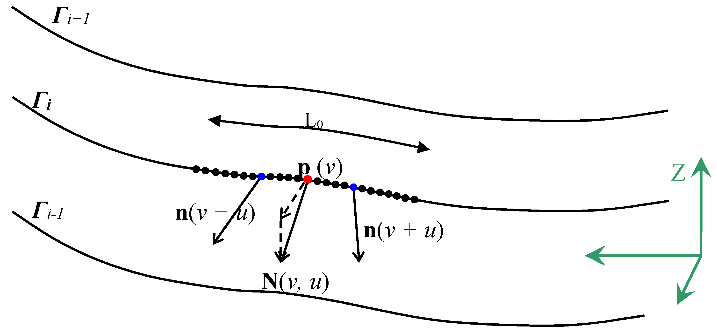
Figure 4.
Local reference systems [11].
Figure 4.
Local reference systems [11].
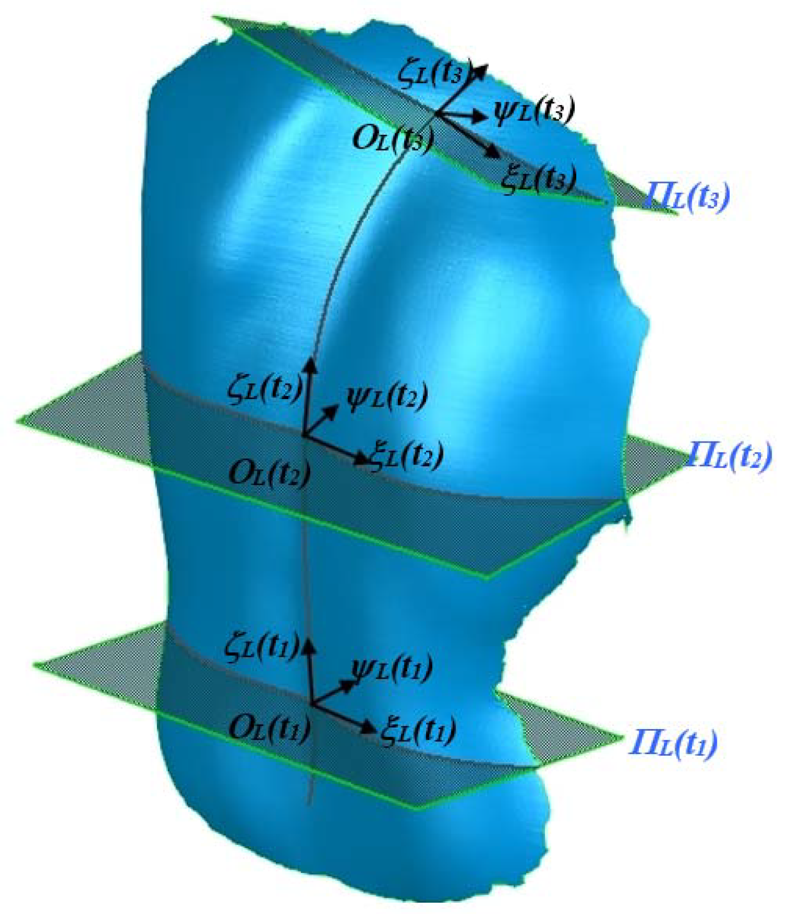
Figure 5.
Refinement algorithm of the NEPA method [11].
Figure 5.
Refinement algorithm of the NEPA method [11].

Figure 6.
Example of NEPA results [11].
Figure 6.
Example of NEPA results [11].
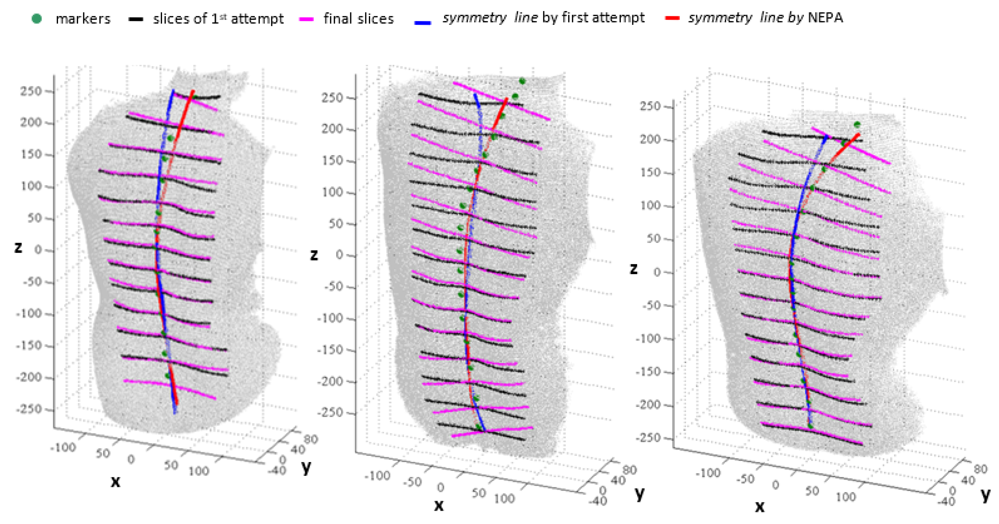
Figure 7.
Graphical description of the refinement algorithm provided in [13].
Figure 7.
Graphical description of the refinement algorithm provided in [13].

Figure 8.
Results using the traditional and the refinement approaches for some significant analysed cases [13].
Figure 8.
Results using the traditional and the refinement approaches for some significant analysed cases [13].
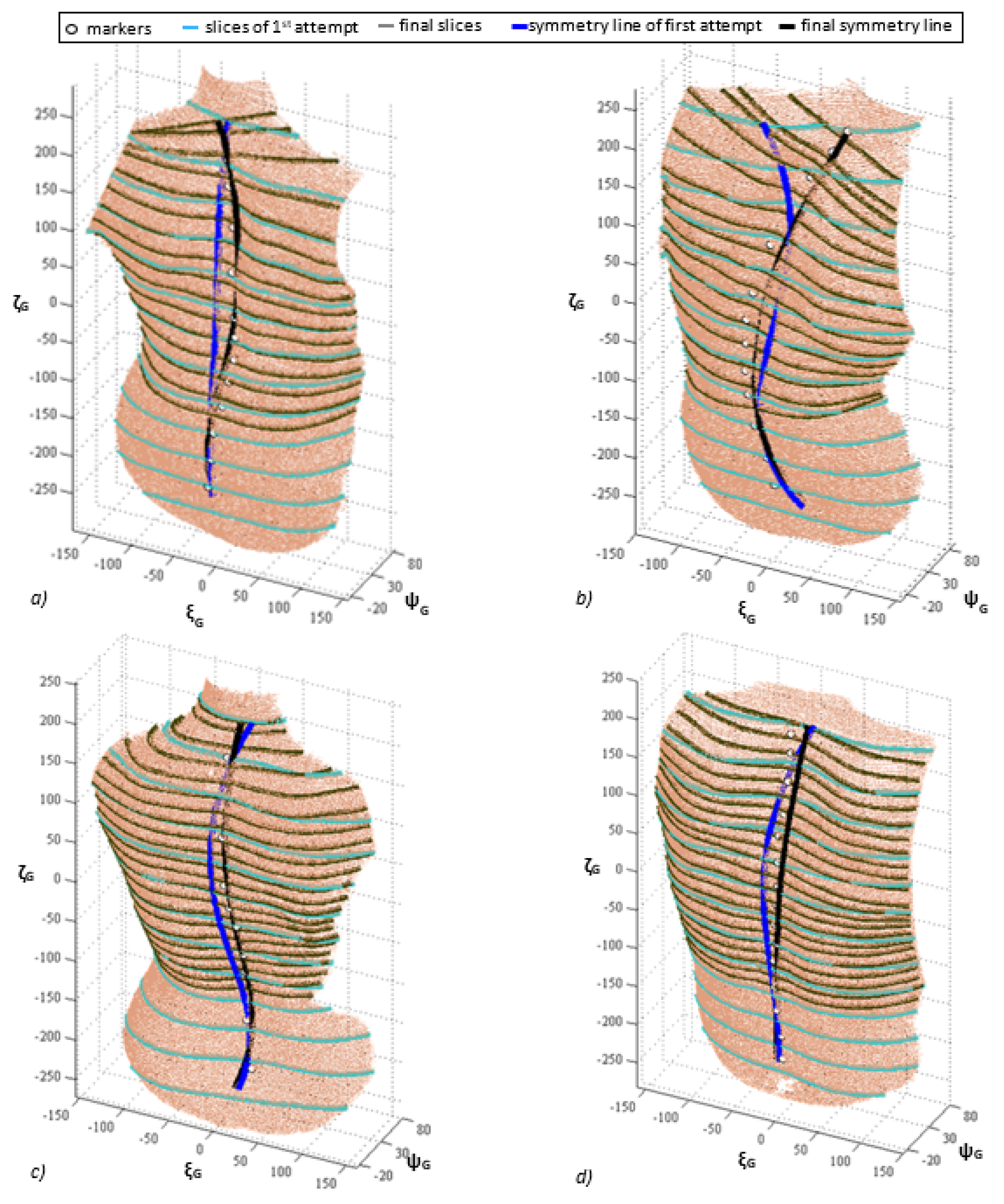
Figure 9.
Results using the traditional and refinement approaches for some significant analysed cases. Mushroom model consisting of quadrilateral and triangular patches (a), the corresponding orientation histogram (b) [14].
Figure 9.
Results using the traditional and refinement approaches for some significant analysed cases. Mushroom model consisting of quadrilateral and triangular patches (a), the corresponding orientation histogram (b) [14].

Figure 10.
Original and mirrored face registered [18].
Figure 10.
Original and mirrored face registered [18].

Figure 11.
Preprocessing scans for use with the FRGC PCA algorithm is a two-step process. The scan is initially processed into its Canonical Face Depth Map CFDM format before the FRGC normalisation algorithm ‘face2norm’ masks out unwanted regions and normalises the depth and colour [22].
Figure 11.
Preprocessing scans for use with the FRGC PCA algorithm is a two-step process. The scan is initially processed into its Canonical Face Depth Map CFDM format before the FRGC normalisation algorithm ‘face2norm’ masks out unwanted regions and normalises the depth and colour [22].

Figure 12.
Example of nose region used for locating the symmetry plane in [23].
Figure 12.
Example of nose region used for locating the symmetry plane in [23].

Figure 13.
Refined symmetry planes from [23].
Figure 13.
Refined symmetry planes from [23].
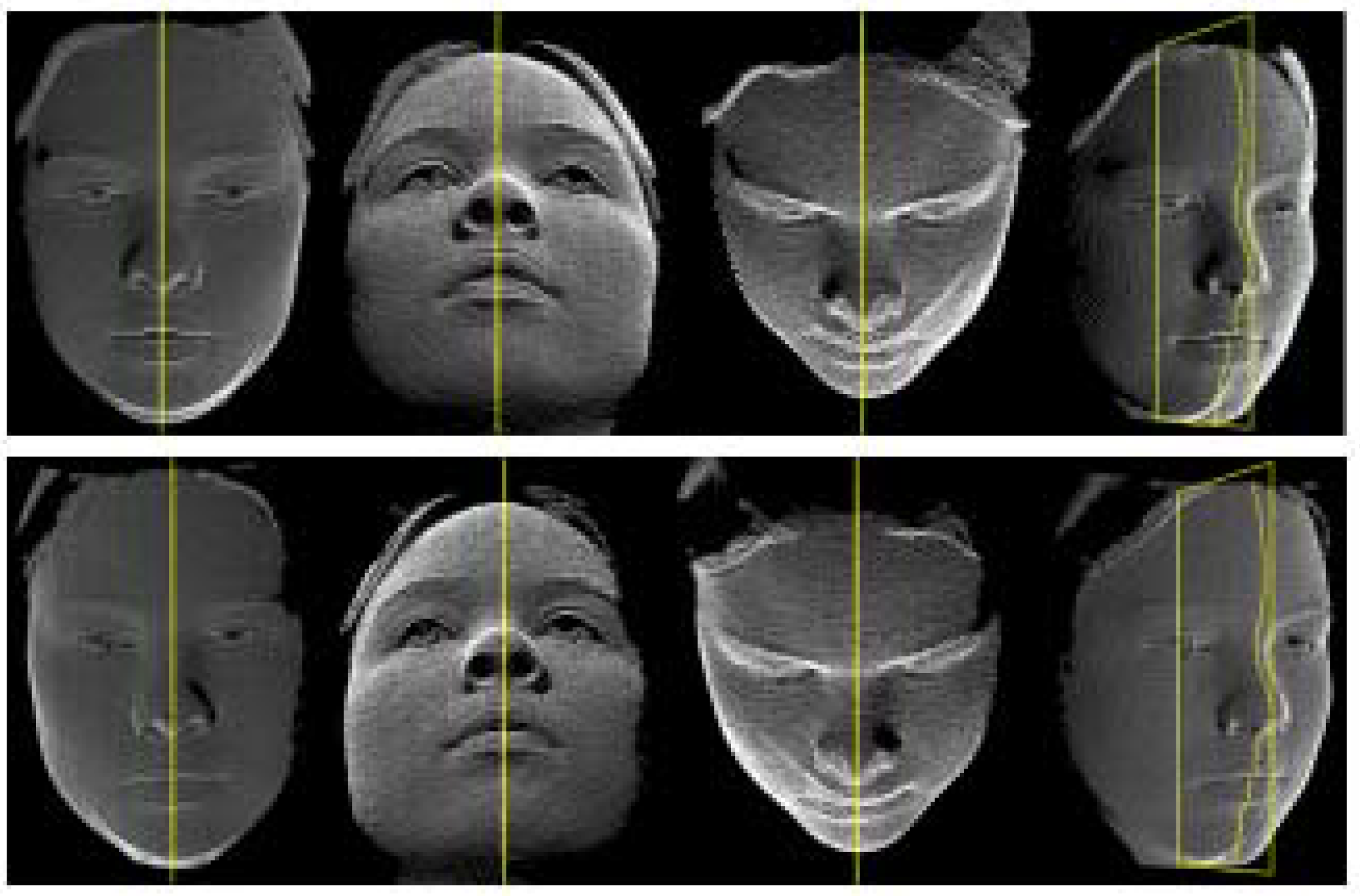
Figure 14.
The MarkSkirt operator. (a) 3D facial mesh characterized by partial/incomplete boundary. (b) Mirrored mesh. (c) Alignment of (a) and (b) by means of ICP algorithm. (d) region between the boundary and the dashed curve on the mirrored mesh. (e) Alignment of the non-skirt region on Sm and original mesh, S. (f–h) Examples where part of the forehead is missing due to the hair occlusion. The red vertices in (f) are S. (g) Evaluated symmetry plane without the use of the MarkSkirt operator. (h) Computed symmetry plane obtained by using the MarkSkirt operator [30].
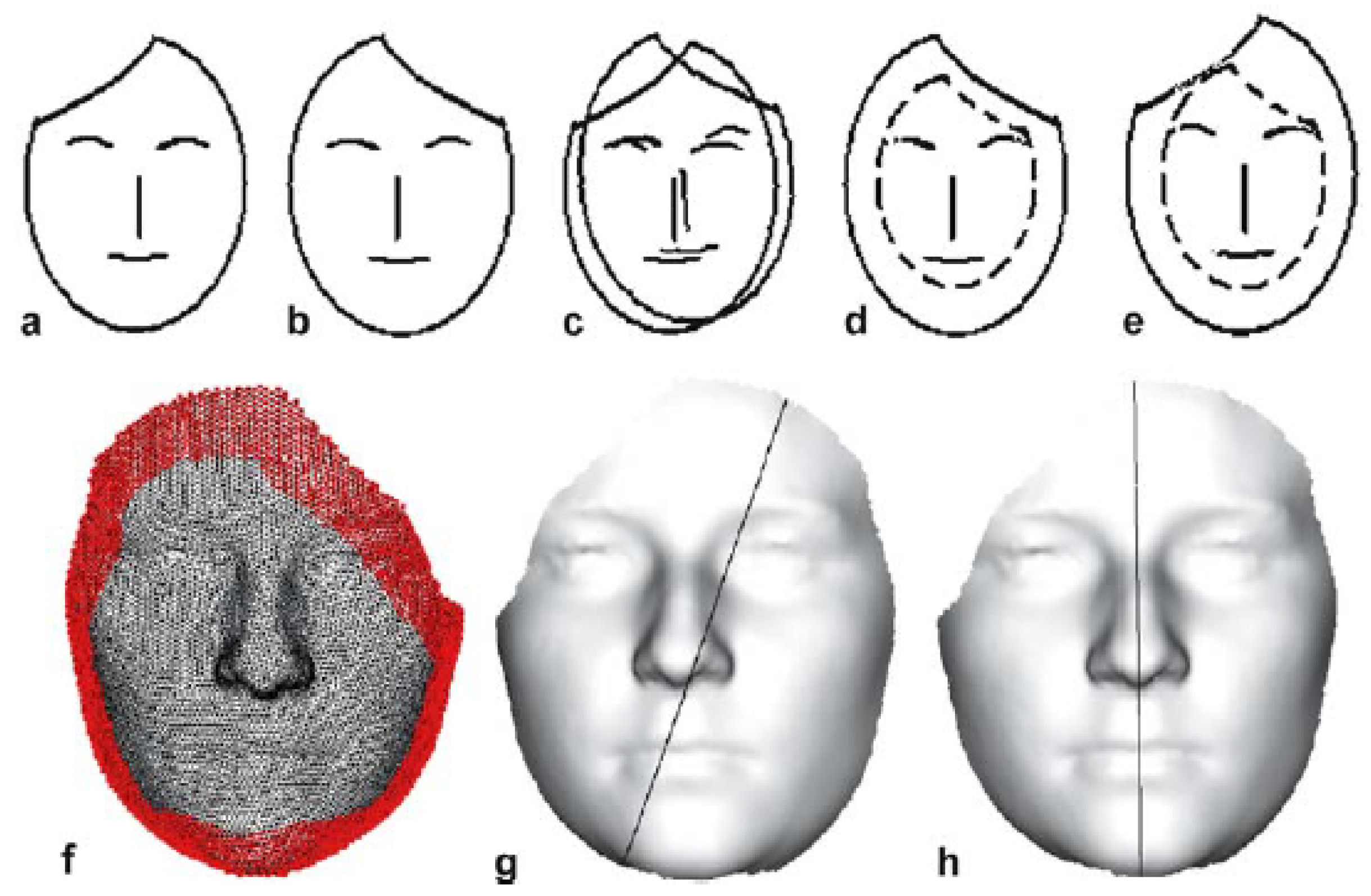
Figure 15.
Cloud-Registration by means of the vertical symmetry plane, slope of the nose bridge and nose tip, taken from [35].
Figure 15.
Cloud-Registration by means of the vertical symmetry plane, slope of the nose bridge and nose tip, taken from [35].

Table 1.
Methods to detect the symmetry line.
| Authors | Description | Advantages | Limitations—Aspects to Be Improved | Performance | |
|---|---|---|---|---|---|
| CUTANEOUS MARKING BASED METHODS | Turner-Smith [12] | 3D position of landmarks manually acquired. Symmetry line evaluated as the broken line jointing the barycentre of each marker. | Early approach for determining the symmetry line based on the 3D data of the back. Good accuracy (estimated in 5 mm). | Need to manually identify the apophyses and apply markers. | Asymmetry correlated with Cobb angle with sample correlation coefficient r = [0.77 – 0.94] and p-value p < 0.0001. r values depending on the number of patients used for the experimentation |
| Sotoca et al. [13] | Spine curve obtained by: - Cutaneous markers positioned in correspondence of the vertebral spinous processes, from C7 to the lumbar vertebra L5; - Projecting the x-ray images on the topographic representation of the surface. Markers location approximated with a polynomial curve. | High correlation (r = 0.89) between this method and the X-ray based one. Good accuracy (estimated in 5 mm). | Asymmetry correlated with Cobb angle with sample correlation coefficient r = 0.89 and p-value p < 0.0001 | ||
| PARALLEL SECTIONS BASED METHODS | Drerup-Hierholzer [10] | Coordinate system associated to the subject’s back. Slicing of the back surface using parallel planes normal to the vertical axis. Position of the spine associated to the minimum value of the lateral asymmetry function. | First methodology based on symmetry properties of the horizontal sections of the subject’s back. | Results could be not compatible with biomechanical constraints. Thousands of instances to be explored to select the most promising set of points, with respect of the work proposed by Santiesteban et al. | Asymmetry correlated with Cobb angle with sample correlation coefficient r = 0.9 and p-value p < 0.0001 |
| Huysmans et al. [14] | Lateral asymmetry function integrated with, blending, curvatures, torsions and biomechanical constraints. | Compared to the work of Drerup—Hierholzer: - Avoids results that could be not compatible with biomechanical constraints; - Applicable to different postures; - Biomechanical constraints and information from previous measurements; - More robust and reliable location of the anatomical landmarks. | Evaluation of six coefficients required to adjust the procedure for analysing average individuals. | Mean r.m.s. error of 0.9 mm for the lateral deviation and 0.4° for the axial rotation when compared with the Drerup-Hierholzer method [10]. | |
| Santiesteban et al. [15] | Principal curvatures directions are used as local shape descriptors of the surface. The cutting plane is defined from the set of centroids and from profile directions. | Fewer instances required, with respect to the method of Drerup-Hierholzer. | Need to estimate and quantify asymmetries in the whole back. | Authors provides a method for estimating and modelling human spine from 3D data but no quantitative assessment is provided. | |
| Di Angelo et al. [16] | Symmetry index defined from normal unit vectors of horizontal sections orientation of the back surface. | With respect to the method proposed by Drerup-Hierholzer, lower errors in the lumbar and thoracic tracts and fewer instances required. | Estimation of symmetry line in the cervical tract is not trivial. | Mean error in mm (w.r.t. Drerup-Hierholzer [10]) for patients: - upright standing: 3.2 (lumbar), 3.5 (thoracic), 4.7 (cervical) - sitting: 2.8 (lumbar), 3.6 (thoracic), 5.2 (cervical) | |
| Final Considerations | Suitable to detect the symmetry line in case of erect postures. | Adequate to analyse postures producing spine configurations protruding outside from the sagittal plane. | |||
| ADAPTIVE SECTIONS BASED METHODS | Di Angelo et al. [17,18] | Starting from a first attempt symmetry line (C0), the NEPA method, iteratively, finds the set of planes Π(t) which define onto the back surface a set of profiles Γ(t) exhibiting the maximum possible symmetry according to the expression in the Equation (4). | Suitable for asymmetric postures with spine configurations lying far outside the sagittal plane. Improving the symmetry line detection of about 6–7%, with respect to the previous method of the authors. | The method finds the symmetry line under two hypothesis: (1) symmetry line spans from the “most symmetric” points of the back; (2) plane Π(t) slices the back in the “most symmetric” profiles. | Mean error reduction w.r.t. the method in [16] equal to: 1.53% (lumbar), 7.59% (thoracic) |
| Di Angelo et al. [19] | This new method analyses the profiles given by the intersection of the back surface with a set of planes Πk orthogonal to the direction identified by the previous pair of symmetry points (each point being at a given distance (“step”) from the previous and the following) | Correct evaluation of the symmetry line even for extremely asymmetric postures. | Strong influence of the body morphology of the subject, especially by those features that produce asymmetry such as gibbosities or other alterations. In those cases, the method could fail and false symmetries could be detected. | Mean error reduction w.r.t. first-attempt symmetry line equal to: 2.2% (lumbar), 21.8% (thoracic), 34.5% (cervical) | |
Table 2.
Methods to detect the symmetry plane.
| Authors | Description | Advantages | Limitations—Aspects to Be Improved | Performance | |
|---|---|---|---|---|---|
| EGI | Sun-Sherrah [14] | Analysis of the recurrence histogram built from the orientation of normal unit vectors from EGI and examination of the EGI map around the principal axes of inertia. | Early EGI-based approach for determining symmetry plane of solids. Effort to reduce computational costs are made. | Not much robust when noisy data are acquired. | Reflectional symmetry evaluated in 1 min. Rotational symmetry evaluated in 1–5 min. Complex medicalimages requires 100 min. Accuracy comparable to the one obtained using the “sphere resolution” |
| Pan et al. [15] | Computation of the orientation histogram by the inverse of the Gaussian curvature. | Increasing robustness in presence of noisy data. | The proposed method should be further tested. | More than 95% of the models have good detection results. Computational time less than 1s (on a Pentium IV 2.0 GHz) | |
| Final Considerations | Results depend on the symmetry of the acquired data. | EGI-based methods are not able to analyse the object symmetry. | |||
| Mirroring and registration model | Benz et al. [24] | Mirroring and registration method applied to support surgical facial reconstruction from an aesthetical point of view. | Computation of symmetry plane using registration algorithms where the symmetry plane is retrieved even in case of asymmetric geometries. The 3D eyes position is evaluated by a provided procedure. | Need to cover a higher number of experimental tests to validate the results. | Mean deviation (mm) of the mirrored position from actual position equal to 1.3 (along x-axis), −0.75 along y-axis and −0.25 along z-axis. |
| De Momi et al. [26] | Early attempt for the estimation of the symmetry plane from manually selected areas. | Applicable to all 3D models related to any anatomical body area. | Areas manually selected. | Time required to obtain a satisfactory result (on average) equal to 10 min for each skull, including computation of the symmetry plane. Mean deviation (mm) of the mirrored position from actual position equal to 1.5 orbital, 1.4 zygomatic, 1.7 maxillary | |
| Colbry-Stockman [27] | First-attempt symmetry plane determined by applying the PCA method. | Fully automatic method. | This approach tends to produce unreliable results when asymmetrically scanned data are used as input (Tang et al.). | Computational time equal to 4 s for 320 × 240 pixel images and to 12 s for 640 × 480 pixel images. Improvement of mid-line normalization over database roll, pitch, and yaw differences equal to, respectively, 0.01° ± 0.58° 0.01° ± 2.01° 0.00° ± 0.79° 2.90 mm ± 7.81 mm | |
| Tang et al. [29] | - Initially guessed symmetry plane passing through the centroid; - Registration performed by analyzing a symmetric rectangular region selected around the nose. | ICP registration insensitive to asymmetrical data. | - It allows a correct estimation of the symmetry plane only in case the actual plane is aligned with the yz—plane of the 3D scanner used for acquisition; - Valid approach only in the case of undistorted noses - rise in terms of computational costs due to the ICP algorithm. | When compared with the FSP method, the improvements scores from 7.1% to 5.5% for the symmetry curve and from 12.0% to 8.9% for the cheek curve | |
| Zhang et al. [30] | MarkSkirt operator is used to assess the registration on the whole point clouds with the exception of the points belonging to the 10–ring of the boundary. | ICP algorithm does not fail in case irregularities in the face boundary are present. | - Texture information are used as an additional clue during face comparison tasks; - expanded database, managed in a more efficient way; - use of the MarkSkirt operator in the recognition process. | 2.8 s to obtain the symmetry profile representation from a facial mesh (1GHz Pentium IV). 10.8% equal error rate and 87.5% rank-one recognition rate. False results mainly caused by extreme expression | |
| Combès et al. [31,32,33] | Estimation of the symmetry plane without the need of intermediate pre-processing operations such as roto–translation and registration. | Solves the problem of non-symmetrical sampling of the face. | Highly sensitive to non uniform sapling. | Angular and linear errors of the estimated symmetry plane compared to the ground truth solution less than 10−2 deg. | |
| Spreeuwers [35] | Not based on ICP algorithm. Symmetry plane estimated by varying a set of parameters in a given range. | Computationally more efficient than the ICP. | The registration method could be further improved and more advanced approaches to select the best configuration of regions classifiers and to evaluate appropriate weights for the voting process could be applied. | Performance of proposed approach w.r.t. Tang et al. [29] shows equal error rates equal to 0.7% against 7.1% (6.1% using manual procedure). Computational time is equal to 2.5. | |
| Di Angelo et al. [37] | First-attempt estimation of the symmetry plane performed by PCA. | Not sensitive to data asymmetry resulting from the scanning process. | Computationally more onerous of the previous ones. | Computational time equal to 11.2 s (average) against 245 s (average) evaluated in Pan et. Al. [21]. Robustness for reproducibility w.r.t. Pan et al. [21] equal to 1.86° (mean value). | |
| Final Considerations | More recent contributions are insensitive to both asymmetrically 3D data and non-uniformity in terms of point cloud density. | Exception made for contributions. The others are sensitive to asymmetries. | |||
© 2018 by the authors. Licensee MDPI, Basel, Switzerland. This article is an open access article distributed under the terms and conditions of the Creative Commons Attribution (CC BY) license (http://creativecommons.org/licenses/by/4.0/).
Share and Cite
MDPI and ACS Style
Bartalucci, C.; Furferi, R.; Governi, L.; Volpe, Y. A Survey of Methods for Symmetry Detection on 3D High Point Density Models in Biomedicine. Symmetry 2018, 10, 263. https://doi.org/10.3390/sym10070263
AMA Style
Bartalucci C, Furferi R, Governi L, Volpe Y. A Survey of Methods for Symmetry Detection on 3D High Point Density Models in Biomedicine. Symmetry. 2018; 10(7):263. https://doi.org/10.3390/sym10070263
Chicago/Turabian StyleBartalucci, Chiara, Rocco Furferi, Lapo Governi, and Yary Volpe. 2018. "A Survey of Methods for Symmetry Detection on 3D High Point Density Models in Biomedicine" Symmetry 10, no. 7: 263. https://doi.org/10.3390/sym10070263
Note that from the first issue of 2016, this journal uses article numbers instead of page numbers. See further details here.