1. Introduction
Two vertical and orthogonal loops, each measuring the magnetic field from a given vertical radiator, can be used to obtain the direction to the source; that is, as a magnetic field direction finder (DF) [
1]. This is the case because the output voltage of a given loop is proportional to the cosine of the angle between the magnetic field vector and the normal vector to the plane of the loop. Therefore, the ratio of the two signals from the loops is proportional to the tangent of the angle between the normal vector to the plane of one of the loops and direction to the source.
Cross-loop magnetic DFs used for lightning detection can be divided into two general types: narrow-band DFs and gated wideband DFs. In both cases, the direction-finding technique involves an implicit assumption that the radiated electric field is oriented vertically and the associated magnetic field is oriented horizontally and perpendicular to the propagation path.
Narrow-band DFs have been used to detect distant lightning since the 1920s [
2,
3]. They generally operate in a narrow frequency band with the center frequency in the 5–10 kHz range. A major disadvantage of narrow-band DFs is that for lightning at distances less than about 200 km, those DFs have inherent azimuthal errors, called polarization errors [
4,
5]. These errors are caused by the detection of magnetic field components from non-vertical channel sections, whose magnetic field lines form circles in a plane perpendicular to the non-vertical channel section. To overcome the problem of large polarization errors at relatively short ranges inherent in the operation of narrow-band DFs, gated wideband DFs were developed in the early 1970s [
6]. Direction finding is accomplished by sampling two orthogonal components of the initial peak of the return-stroke magnetic field, that peak being radiated from the bottom hundred meters or so of the channel in the first microseconds of the return stroke. Since the bottom of the channel tends to be straight and vertical, the magnetic field lines form circles in a horizontal plane. The operating bandwidth of the gated wideband DF is typically from a few kilohertz to about 500 kHz. Gated wideband DFs, as well as narrow-band DFs, are susceptible to site errors, which are caused by the presence of unwanted magnetic fields due to non-flat terrain and to nearby conducting structures being excited to radiate by the incoming lightning fields.
In multiple-station lightning locating systems (LLSs), such as the U.S. National Lightning Detection Network (NLDN), the direction to lightning is estimated on the basis of the ratio of the peaks of magnetic fields measured by two orthogonal loop antennas, and the lightning location is estimated using the directions reported by multiple pairs of loop antennas.
In countries like Japan, there are often mountains and tall conducting structures near magnetic direction finding stations. As a result, the direction (azimuth) estimated from two orthogonal magnetic fields may be influenced by the presence of mountain and/or conducting structures.
In this paper, lightning electromagnetic fields in the presence of conducting (grounded) structure having a height of 60 m and a square cross-section of 40 m × 40 m within about 100 m of the field measuring point are calculated using the 3D finite-difference time-domain (FDTD) method [
7]. Influence of the presence of conducting structure on lightning magnetic fields at the observation point is studied, and the resultant direction (azimuth) errors are discussed. Influences of ground conductivity and lightning current waveshape parameters are also studied. The influence (variation) of structure height is not considered in this paper.
2. Methodology
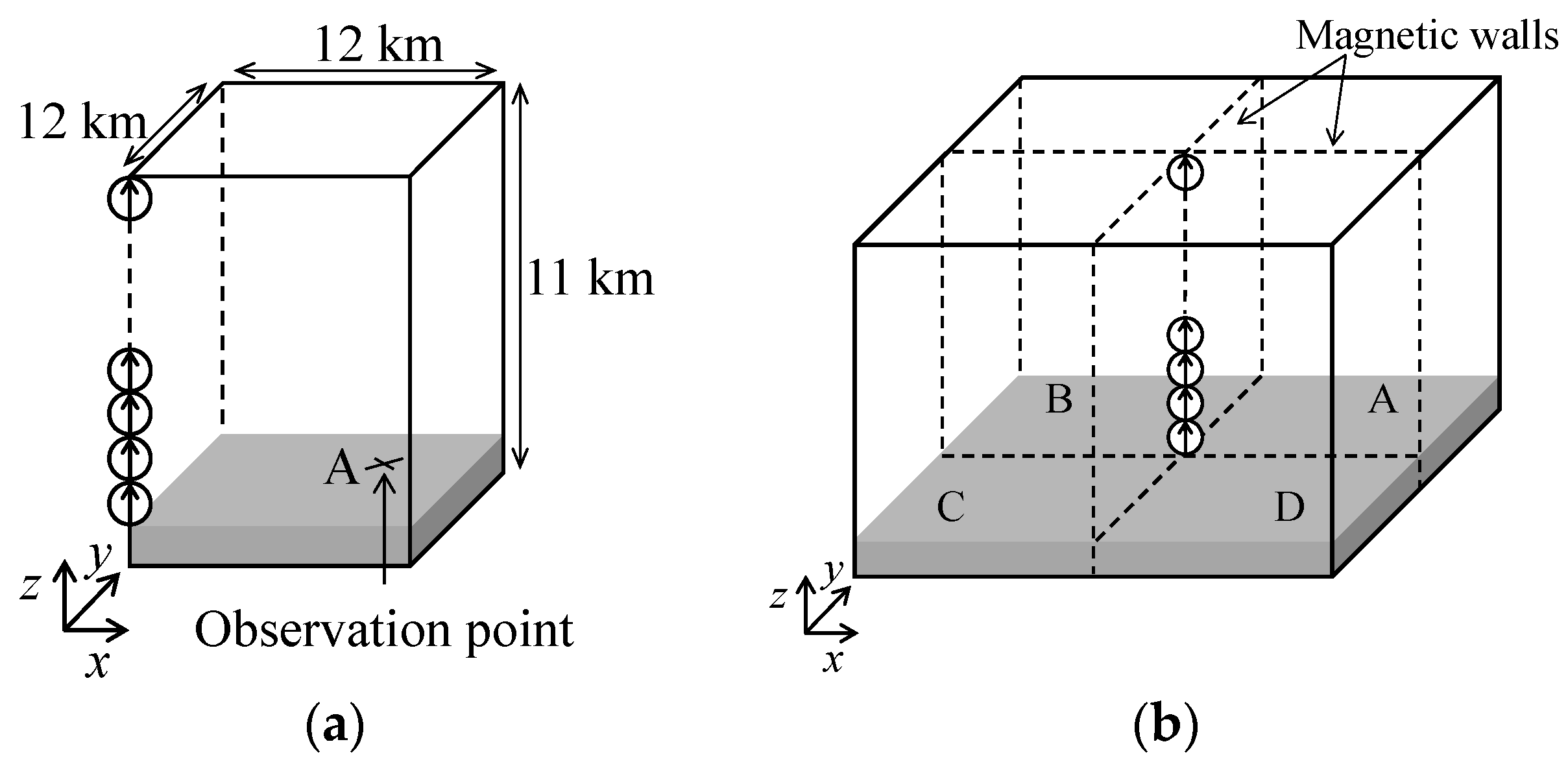
Figure 1a shows the FDTD simulation model of a vertical lightning channel above flat ground. The working volume of 12 km × 12 km × 11 km is divided uniformly into 20 m × 20 m × 20 m cubic cells. The time increment is set to 38.1 ns, which fulfills the Courant stability condition. The ground thickness (between the ground surface and the bottom absorbing boundary condition plane) is set to 1 km, and the ground conductivity is set to a value in the range from 0.1 to 1000 mS/m or to ∞ (perfect conductor). The
xz plane and the
yz plane passing through the source (see
Figure 1) are set to be magnetic walls, and other boundaries are each represented by Liao’s second-order absorbing boundary condition [
8]. Magnetic wall in the FDTD simulation is represented by forcing the tangential magnetic field components on the wall surface to zero. This makes the working volume shown in
Figure 1a equivalent to that shown in
Figure 1b. The lightning channel is represented by a vertical phased-current-source array [
9], which is located at (
x,
y) = (0, 0) of the working volume. The array is activated so as to simulate the current distribution predicted by the transmission-line (TL) model [
10]. The return-stroke current waveform is represented using the sum of the Heidler function [
11] and a double-exponential function, given as follows:
This function reproduces the observed concave rising portion of typical lightning current waveform. In the present simulations, I01 = 11 kA, I02 = 7.5 kA, τ2 = 5.0 μs, τ3 = 100 μs, and τ4 = 6.0 μs. For representing 10%-to-90% risetime of 0.5, 1, and 3 μs, τ1 = 0.305, 0.75, and 4.026 μs, and η = 0.836, 0.717, and 0.34585, respectively. The return-stroke speed is set to 1.5 × 10⁸ m/s (one half of the speed of light).
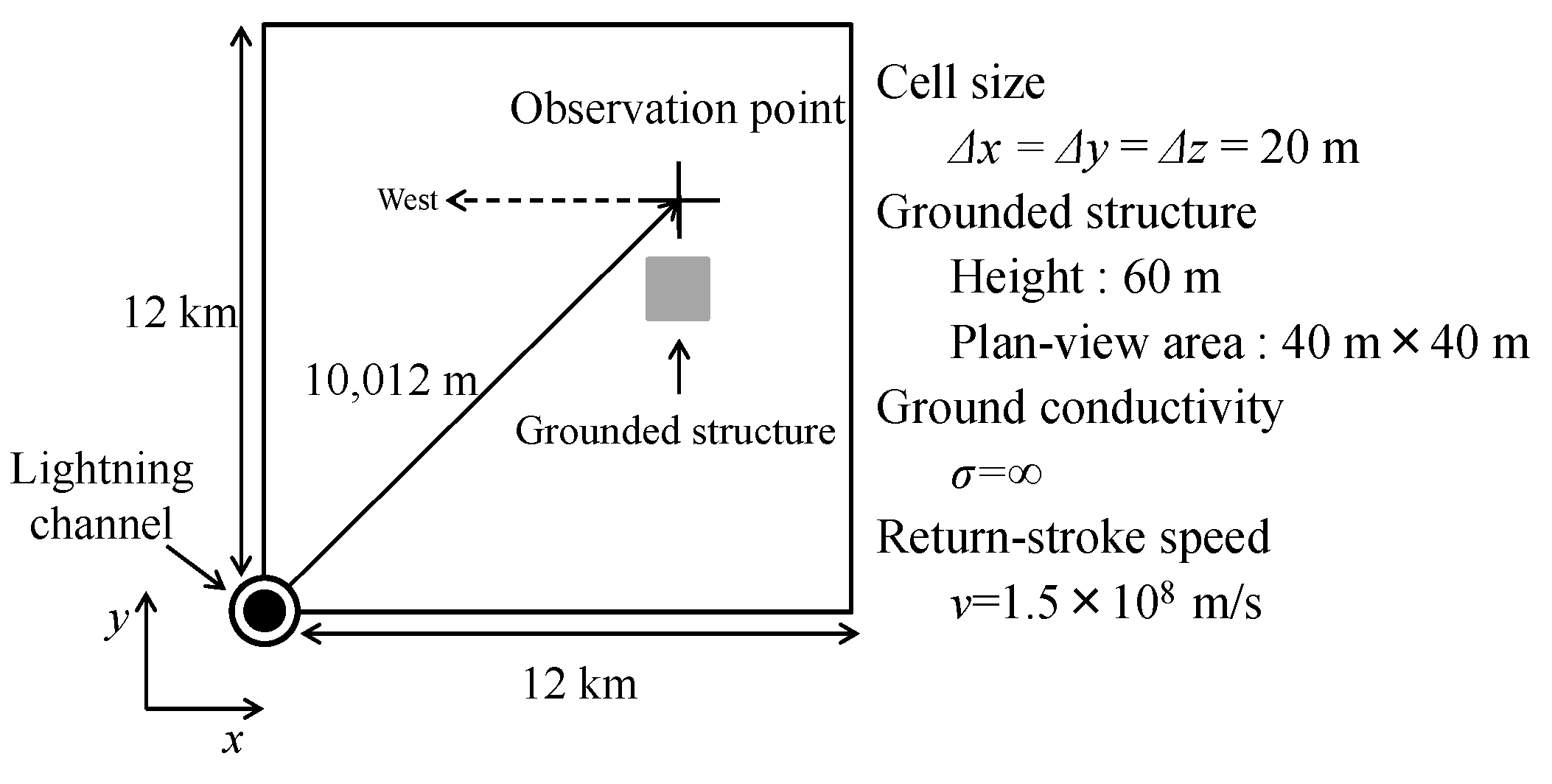
Figure 2 shows plan view of the configuration used for studying fields in the presence of a conducting (grounded) structure having a cross-section of 40 m × 40 m. The point at which the magnetic field is observed is located at (
x,
y) = (7080 m, 7080 m), which is 10,012 m (10.012 km) away from the lightning channel and the azimuth angle is 45° with respect to the
x-axis (and
y-axis) in the
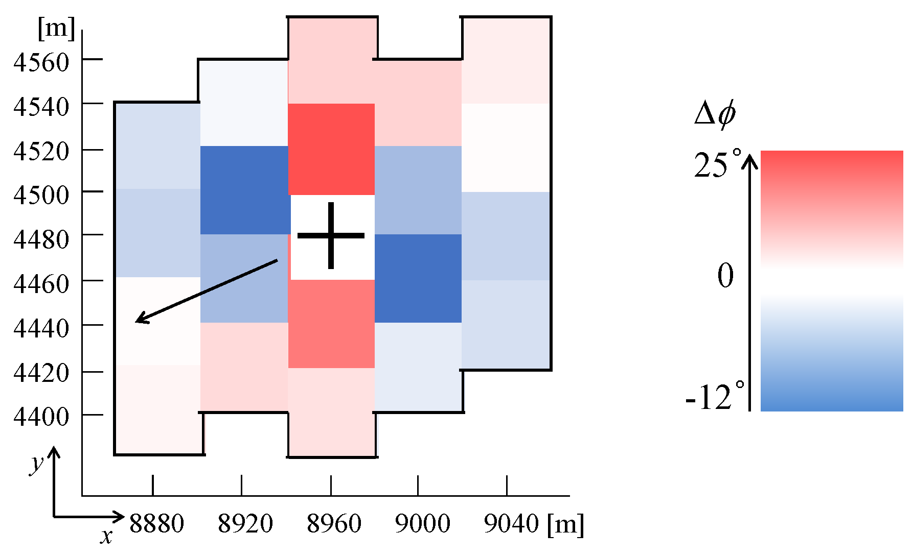
xy plane. Also, computations were carried out for observation points at (
x,
y) = (8960 m, 4480 m) and (10,000 m, 0 m), which are 10,017 m and 10,000 m, respectively, away from the lightning channel and the azimuth angles are 26.6° (tan
−1 φ = 0.5) and 0° with respect to the
x-axis and in the
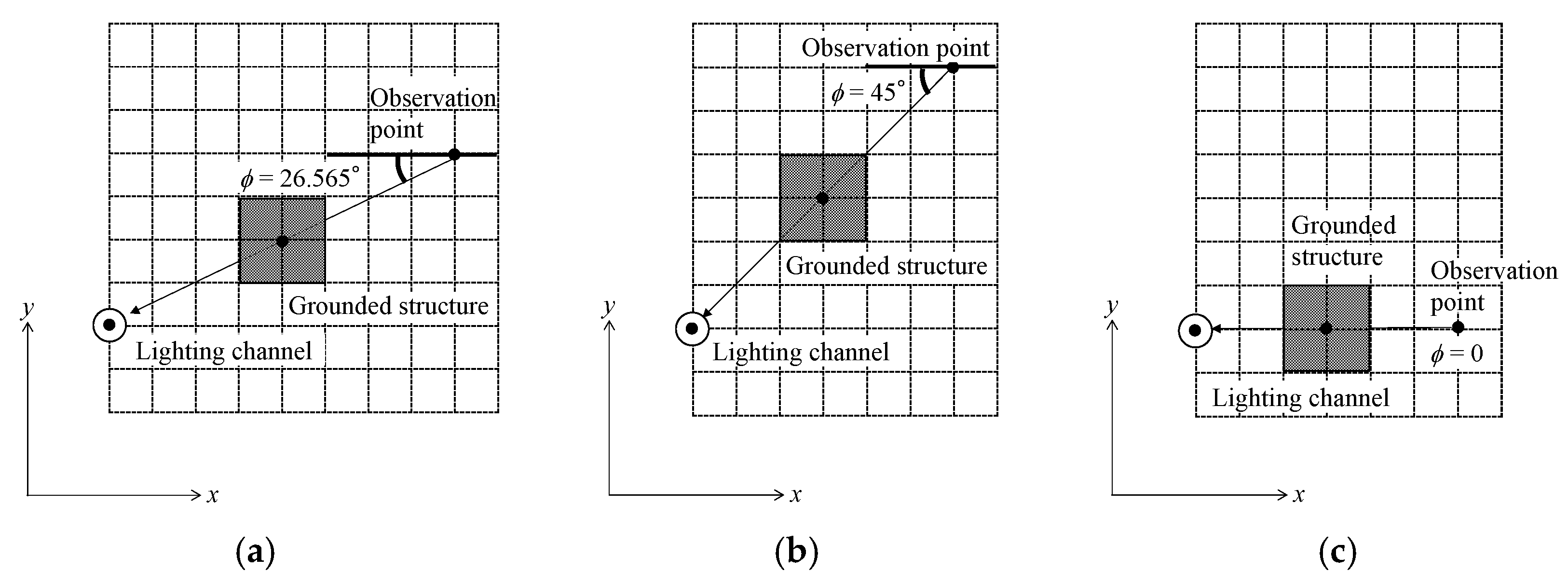
xy plane. Note that the azimuth vector passes through the conducting structure diagonally for
φ = 45°, parallel to its walls for
φ = 0° while it passes through the structure neither diagonally nor in parallel to its walls for
φ = 26.6°.
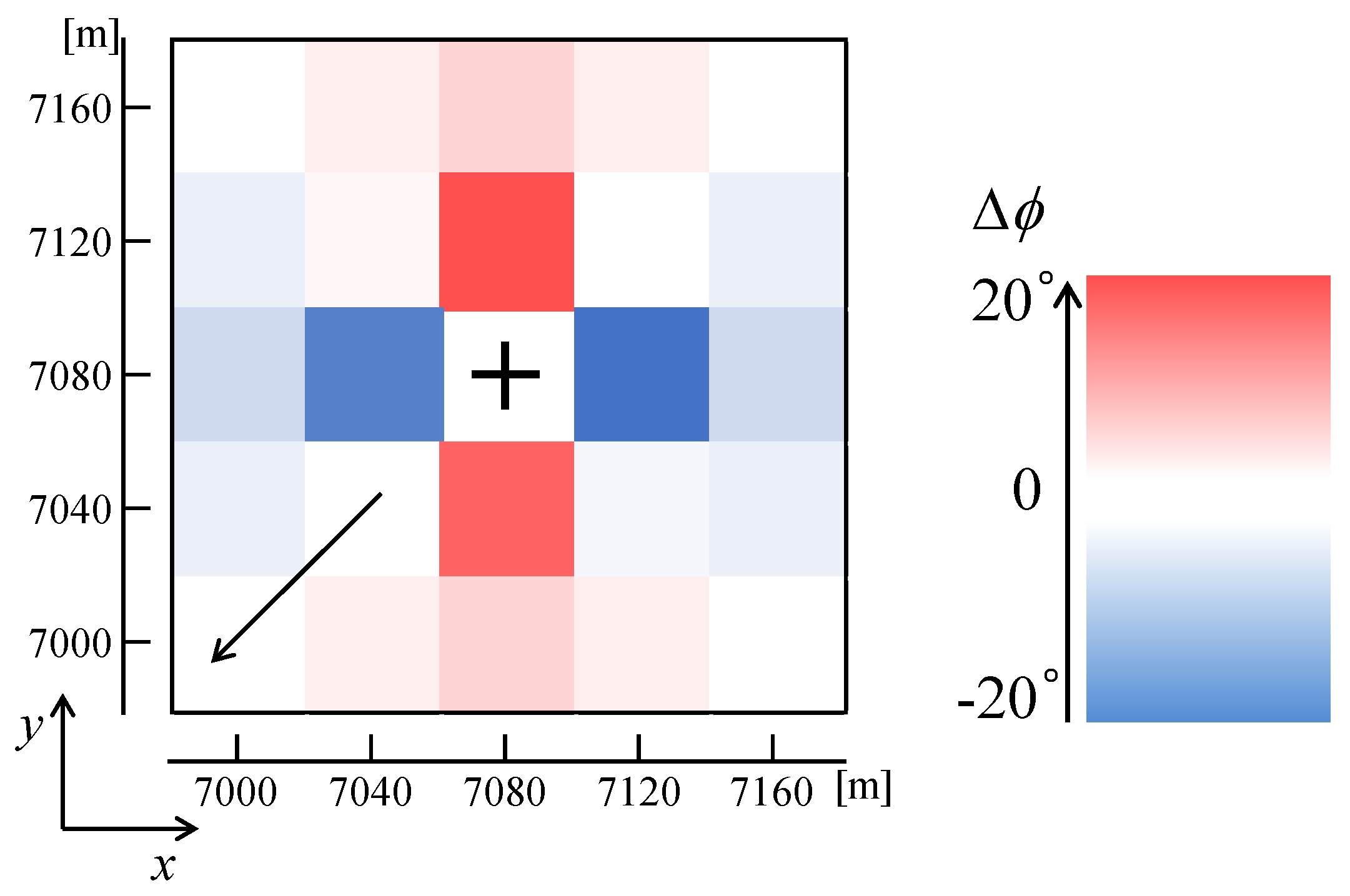
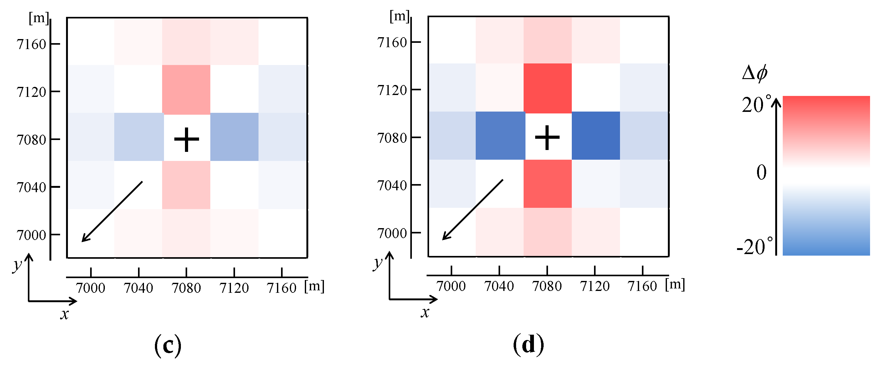
The conducting structure is represented by a perfectly-conducting rectangular parallelepiped of 40 m × 40 m × 60 m, which is centered at different points near the magnetic-field observation point in quadrant A. Note that computations for structure conductivities of 0.1, 1, 10, 100 and 1000 mS/m were also performed. The total number of positions of the conducting structure was 24, located within a square area of 200 m × 200 m, at the center of which (7080 m, 7080 m) the magnetic-field observation point was located for the case of azimuth angle equal to 45° (this arrangement is clearly seen in the figures found in
Section 3.2–
Section 3.5). Identical conducting structures are present in quadrants B, C, and D, because of the symmetry due to the employed magnetic walls, as shown in
Figure 1b. Since the structures in quadrants B, C, and D are far away from those in quadrant A and from the observation point, their influence on fields calculated in quadrant A is small.
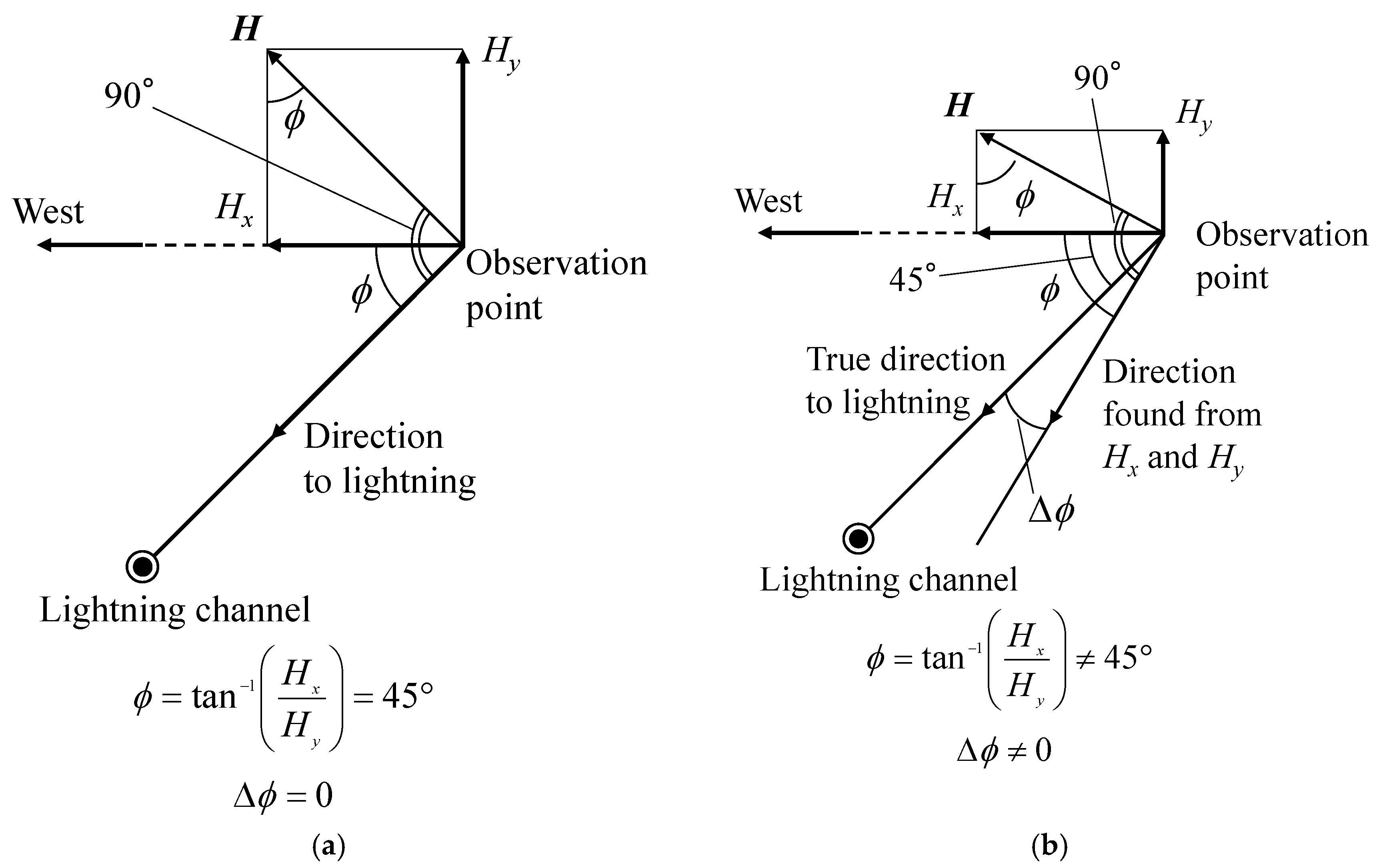
The direction error
Δφ in degrees for the true azimuth angle
φ equal to 45° is calculated from Equation (2) given below:
where
Hx and
Hy are peak values of magnetic field in two orthogonal (east-west and south-north, respectively) directions at the observation point. The first term is the azimuth found from the ratio of
Hx to
Hy, and the second term is the true azimuth for the configuration shown in
Figure 2.
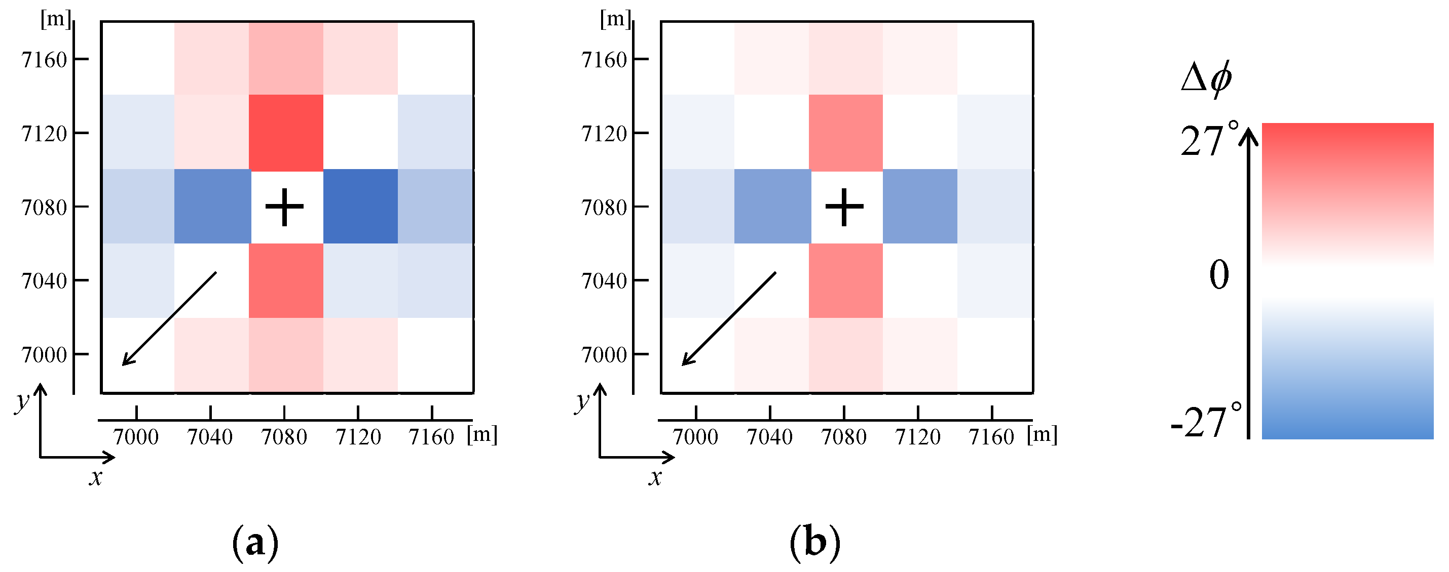
Figure 3a,b illustrate two cases with
Δφ = 0°and
Δφ = 16°, respectively, for
φ = 45°. Note that magnetic fields in the west direction (negative
x direction) and in the north direction (positive
y direction) are each defined as positive.
4. Conclusions
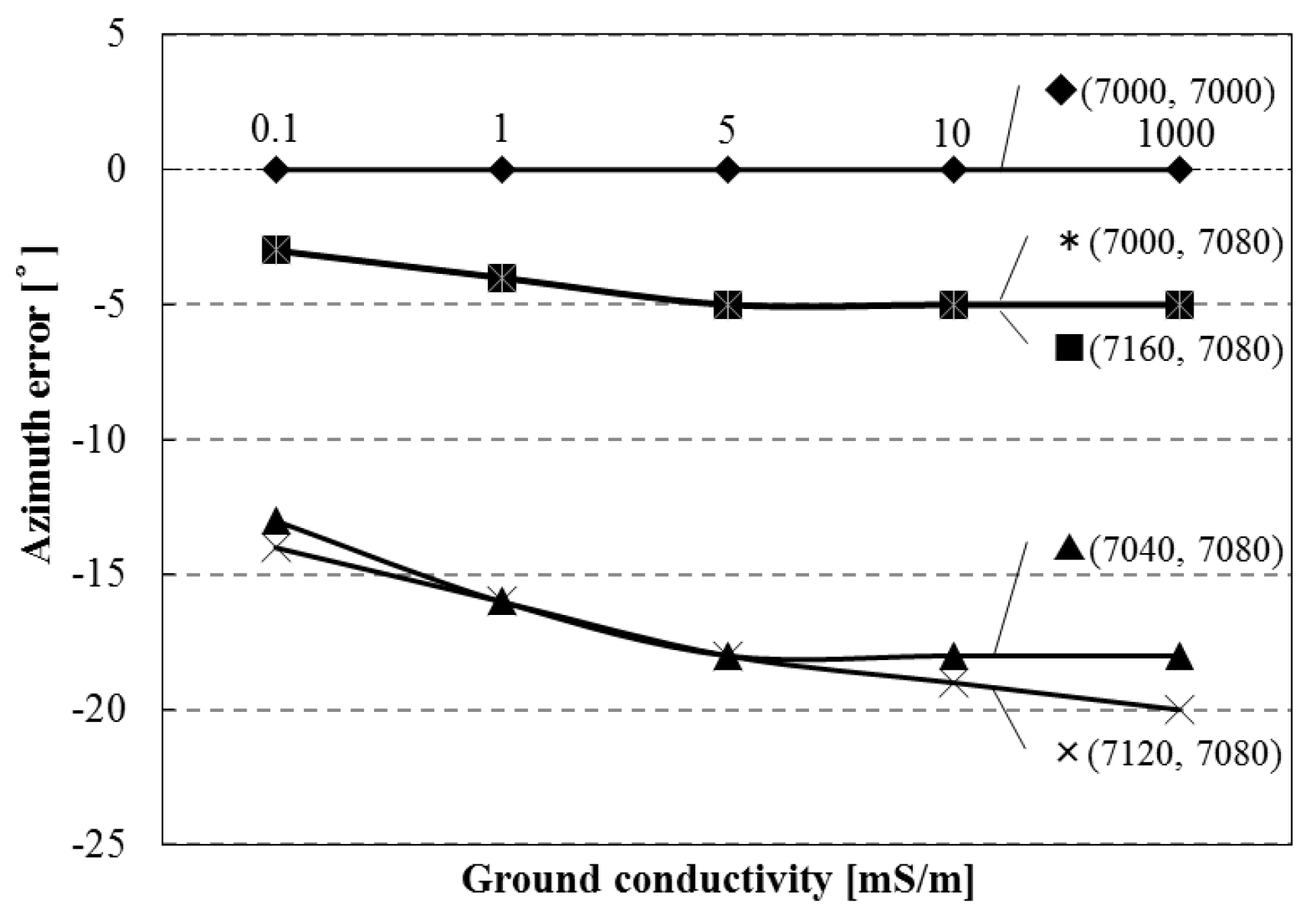
In this paper, lightning electromagnetic fields in the presence of conducting structure having a height of 60 m and a square cross-section of 40 m × 40 m within about 100 m of the field point have been analyzed using the 3D FDTD method. Influence of the structure on the two orthogonal components of magnetic field, Hx and Hy, has been analyzed, and the resultant error in the estimated lightning azimuth has been studied. When the azimuth vector passes through the center of conducting structure diagonally (e.g., azimuth angle is 45°) or parallel to its walls (e.g., azimuth angle is 0°), the presence of structure equally influences Hx and Hy, so that Hx/Hy is the same as in the absence of structure. As a result, no azimuth error occurs in those configurations. When the structure is not located on that line, its influence is greater when it is located closer to the observation point. If the distance from the structure to the observation point is the same, the influence of structure behind the observation point is more significant than that in front of it. The azimuth error due to the presence of structure depends on the risetime of lightning current. When the current risetime is 0.5 μs, the azimuth error is generally larger than those for risetimes equal to 1 or 3 μs, except for some specific locations. The azimuth error due to the presence of structure decreases with decreasing ground conductivity. As the structure conductivity decreases, the azimuth error becomes smaller.


