Improved Mechanical Properties of Copoly(Phthalazinone Ether Sulphone)s Composites Reinforced by Multiscale Carbon Fibre/Graphene Oxide Reinforcements: A Step Closer to Industrial Production

Abstract
:1. Introduction
2. Experiment
2.1. Materials
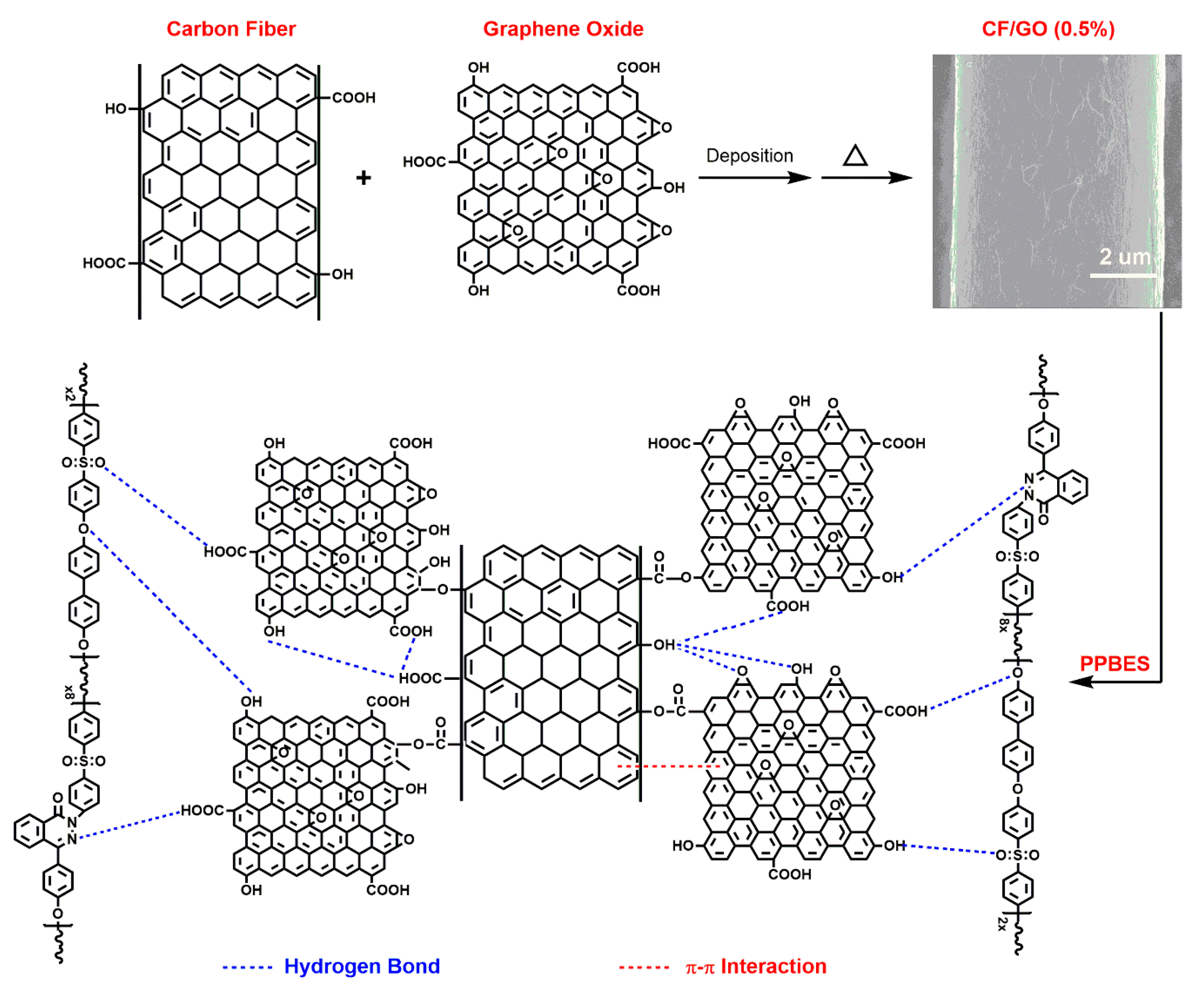
2.2. Preparation of CF/GO Hierarchical Reinforcements
2.3. Preparation of CF/PPBES Composites
2.4. Characterization
3. Results and Discussion
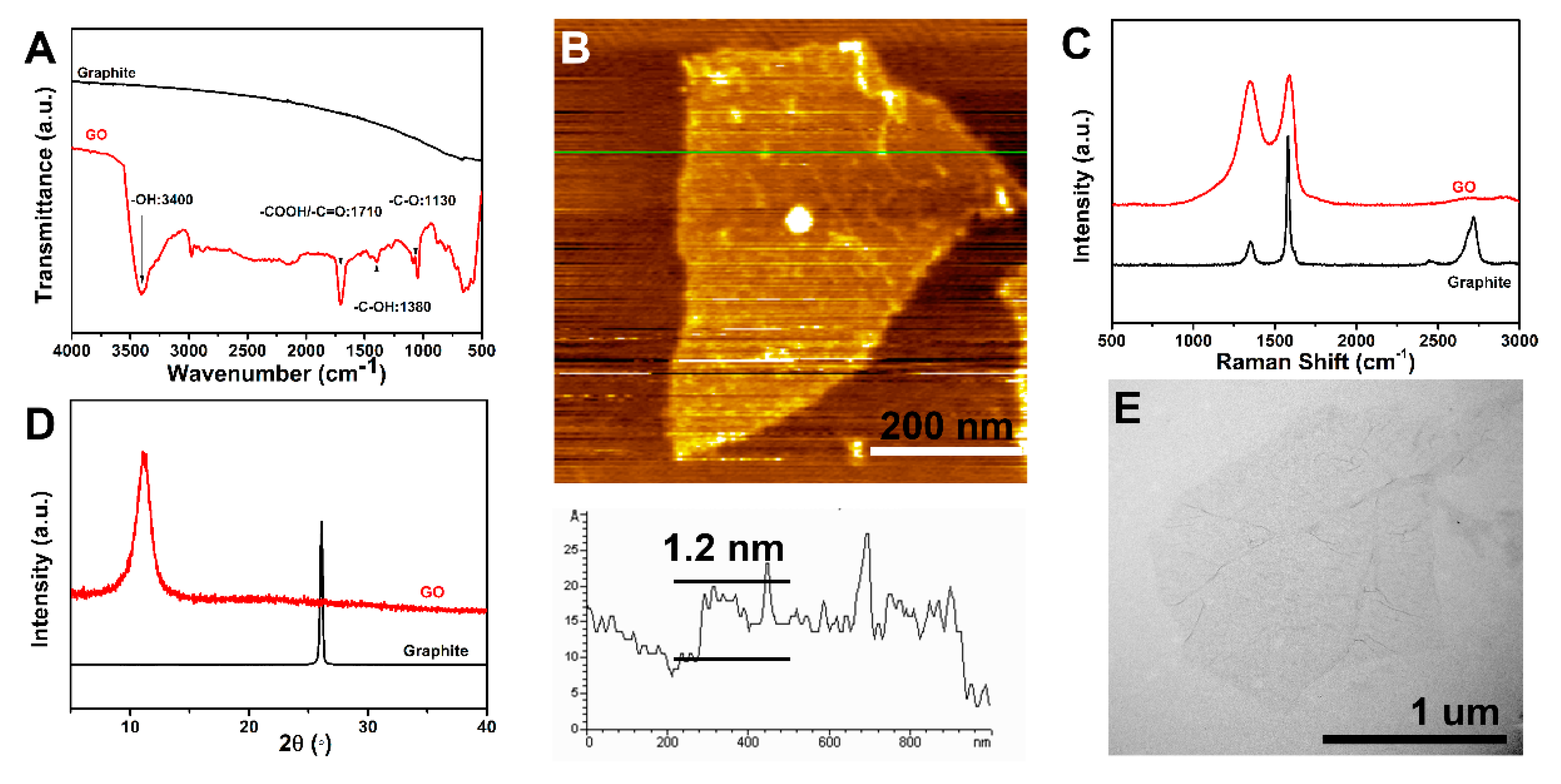
3.1. Preparation of GO
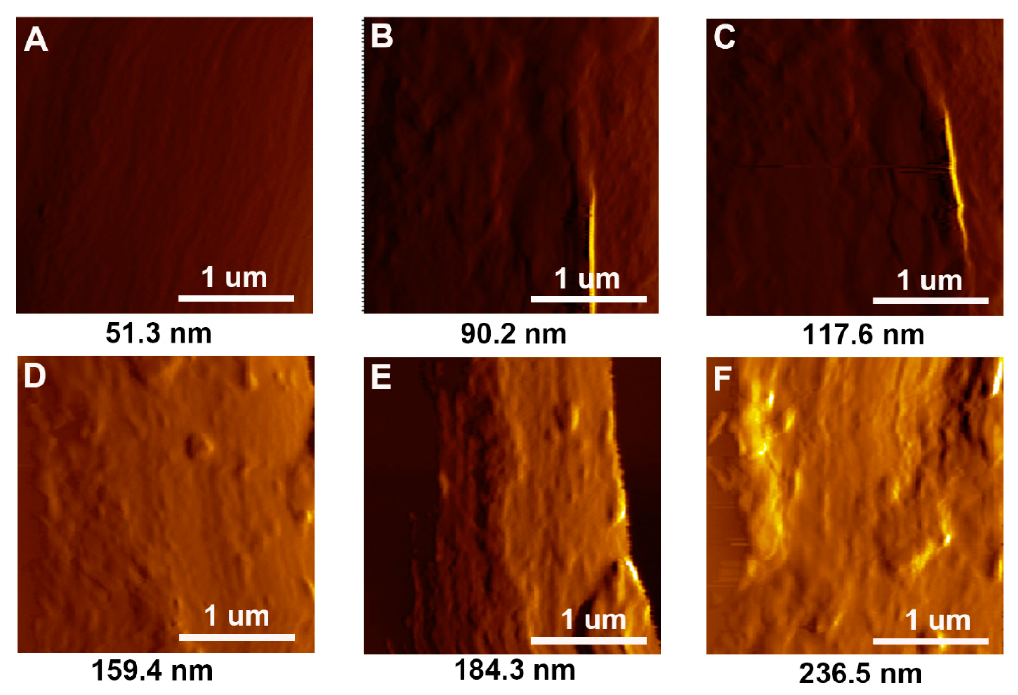
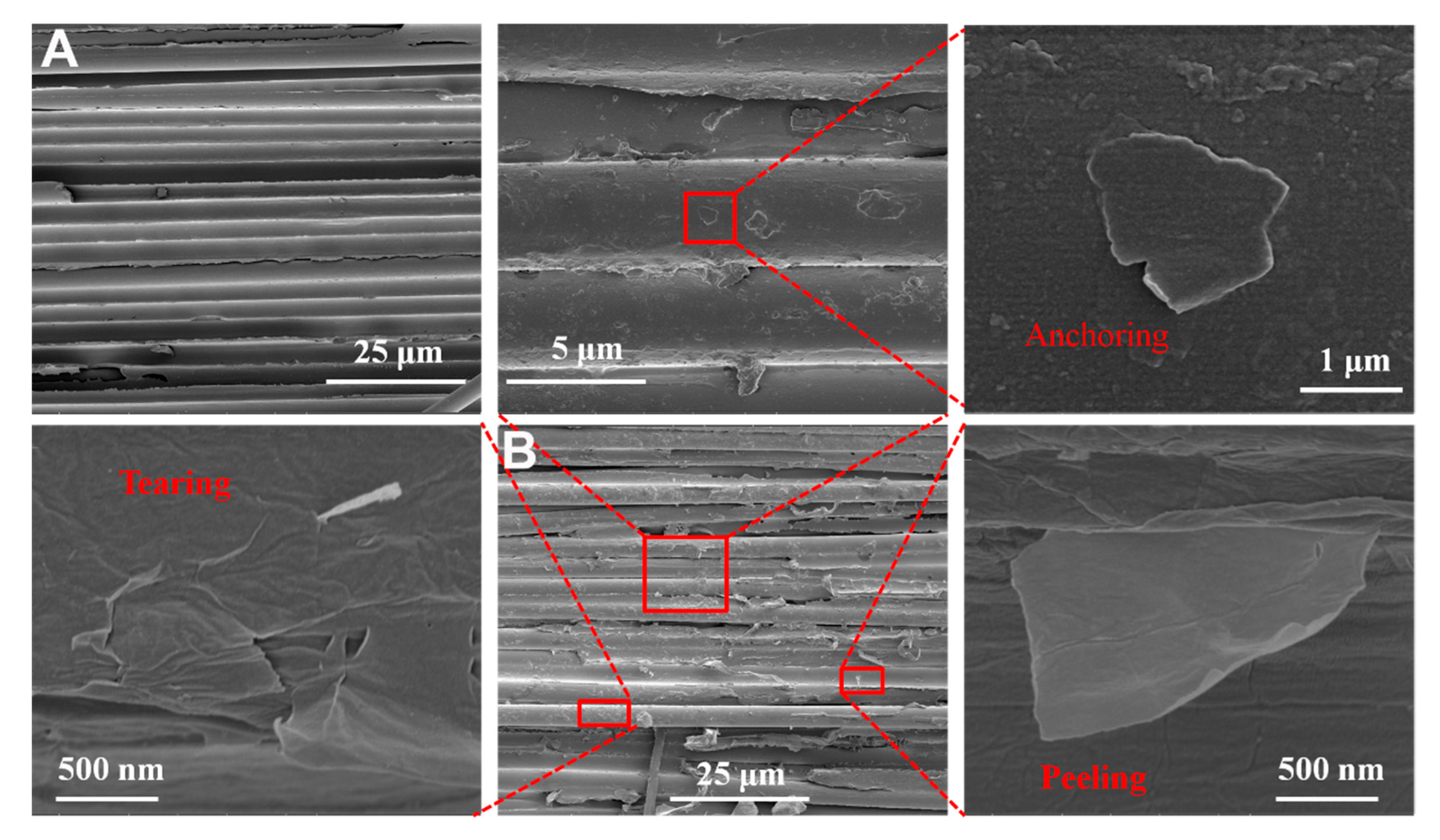
3.2. Surface Morphologies of CFs
3.3. Surface Chemical Elemental Compositions of CFs
3.4. Wettability of CFs
3.5. Composites Mechanical Property Testing
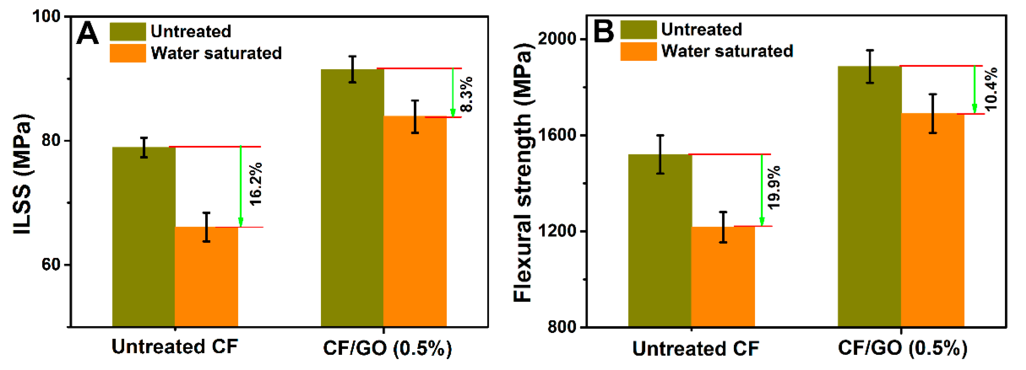
3.6. Hydrothermal Ageing Performance of Composites
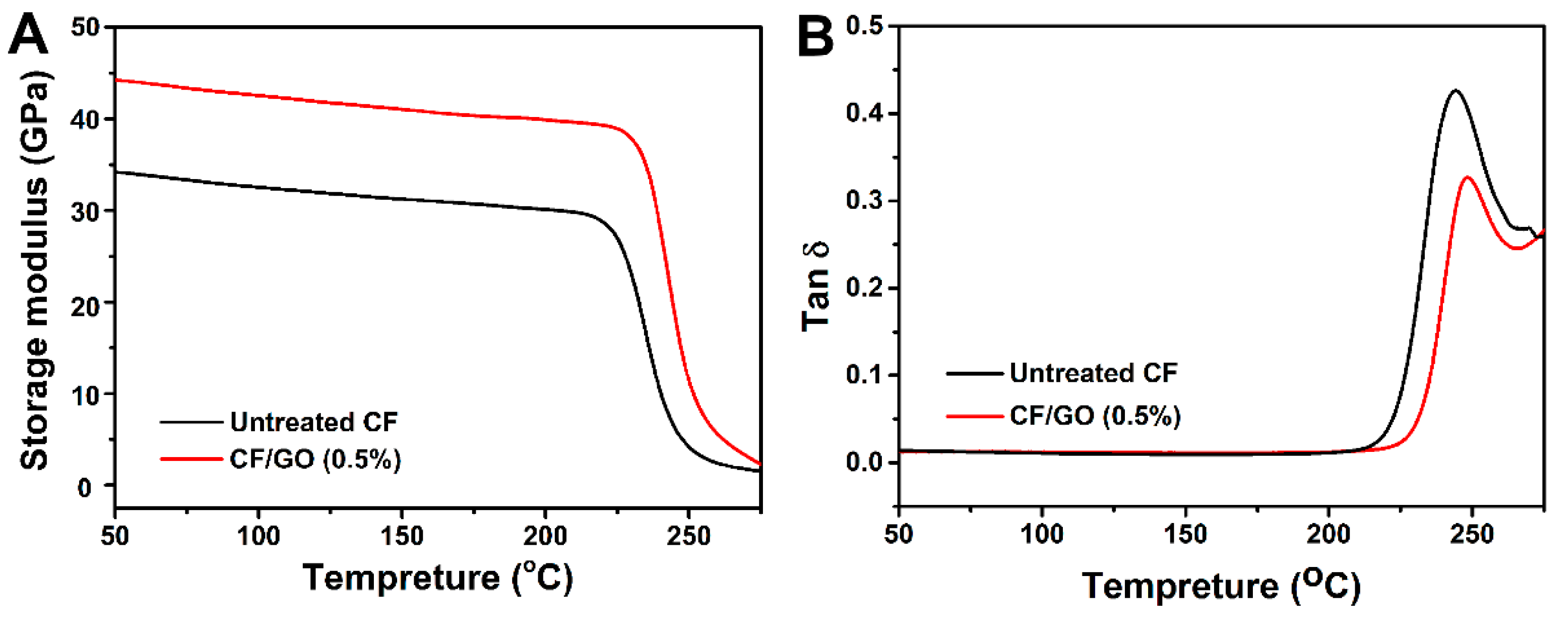
3.7. Dynamic Mechanical Properties
4. Conclusions
Author Contributions
Funding
Acknowledgments
Conflicts of Interest
References
- Li, N.; Wu, Z.Q.; Yang, X.X.; Wang, C.H.; Zong, L.S.; Pan, Y.X.; Wang, J.Y.; Jian, X.G. One-pot strategy for covalent construction of POSS-modified silane layer on carbon fiber to enhance interfacial properties and anti-hydrothermal aging behaviors of PPBES composites. J. Mater. Sci. 2018, 53, 16303–16317. [Google Scholar] [CrossRef]
- Li, N.; Zong, L.S.; Wu, Z.Q.; Liu, C.; Wang, X.; Bao, F.; Wang, J.Y.; Jian, X.G. Amino-terminated nitrogen-rich layer to improve the interlaminar shear strength between carbon fiber and a thermoplastic matrix. Compos. Part A Appl. 2017, 101, 490–499. [Google Scholar] [CrossRef]
- Wang, Z.K.; Xian, G.J.; Zhao, X.L. Effects of hydrothermal aging on carbon fibre/epoxy composites with different interfacial bonding strength. Constr. Build. Mater. 2018, 161, 634–648. [Google Scholar] [CrossRef]
- Semitekolos, D.; Kainourgios, P.; Jones, C.; Rana, A.; Koumoulos, E.P.; Charitidis, C.A. Advanced carbon fibre composites via poly methacrylic acid surface treatment; surface analysis and mechanical properties investigation. Compos. Part B Eng. 2018, 155, 237–243. [Google Scholar] [CrossRef]
- Gao, B.; Zhang, R.L.; He, M.S.; Wang, C.G.; Liu, L.; Zhao, L.F.; Wen, Z.J.; Ding, Z.P. Interfacial microstructure and mechanical properties of carbon fiber composites by fiber surface modification with poly (amidoamine)/polyhedral oligomeric silsesquioxane. Compos. Part A Appl. 2018, 90, 653–661. [Google Scholar] [CrossRef]
- Zhang, X.Q.; Fan, X.Y.; Yan, C.; Li, H.; Zhu, Y.D.; Li, X.T.; Yu, L.P. Interfacial microstructure and properties of carbon fiber composites modified with graphene oxide. ACS Appl. Mater. Interfaces 2012, 4, 1543–1552. [Google Scholar] [CrossRef] [PubMed]
- Chen, L.; Jin, H.; Xu, Z.W.; Shan, M.J.; Tian, X.; Yang, C.Y.; Wang, Z.; Chen, B.W. A design of gradient interphase reinforced by silanized graphene oxide and its effect on carbon fiber/epoxy interface. Mater. Chem. Phys. 2014, 145, 186–196. [Google Scholar] [CrossRef]
- Yang, X.B.; Jiang, X.; Huang, Y.D.; Guo, Z.H.; Shao, L. Building Nanoporous Metal-Organic Frameworks “Armor” on Fibers for High-Performance Composite Materials. ACS Appl. Mater. Interfaces 2017, 9, 5590–5599. [Google Scholar] [CrossRef]
- Wu, G.S.; Ma, L.C.; Wang, Y.W.; Liu, L.; Huang, Y.D. Interfacial properties and impact toughness of methylphenylsilicone resin composites by chemically grafting POSS and tetraethylenepentamine onto carbon fibers. Compos. Part A Appl. 2016, 84, 1–8. [Google Scholar] [CrossRef]
- Li, N.; Wu, Z.Q.; Huo, L.; Zong, L.S.; Guo, Y.J.; Wang, J.Y.; Jian, X.G. One-step functionalization of carbon fiber using in situ generated aromatic diazonium salts to enhance adhesion with PPBES resins. RSC Adv. 2016, 6, 70704–70714. [Google Scholar] [CrossRef]
- Yuan, H.J.; Zhang, S.C.; Lu, C.X. Surface modification of carbon fibers by a polyether sulfone emulsion sizing for increased interfacial adhesion with polyether sulfone. Appl. Surf. Sci. 2014, 317, 737–744. [Google Scholar] [CrossRef]
- Zhang, K.; Zhang, G.; Liu, B.Y.; Wang, X.J.; Long, S.R.; Yang, J. Effect of aminated polyphenylene sulfide on the mechanical properties of short carbon fiber reinforced polyphenylene sulfide composites. Compos. Sci. Technol. 2014, 98, 57–63. [Google Scholar] [CrossRef]
- Zhang, C.X.; Wu, G.S.; Jiang, H. Tuning interfacial strength of silicone resin composites by varying the grafting density of octamaleamic acid-POSS modified onto carbon fiber. Compos. Part A Appl. 2018, 109, 555–563. [Google Scholar] [CrossRef]
- Zhao, F.; Huang, Y.D.; Liu, L.; Bai, Y.P.; Xu, L.W. Formation of a carbon fiber/polyhedral oligomeric silsesquioxane/carbon nanotube hybrid reinforcement and its effect on the interfacial properties of carbon fiber/epoxy composites. Carbon 2011, 49, 2624–2632. [Google Scholar] [CrossRef]
- Sui, X.H.; Shi, J.; Yao, H.W.; Xu, Z.W.; Chen, L.; Li, X.J.; Ma, M.J.; Kuang, L.Y.; Fu, H.J.; Deng, H. Interfacial and fatigue-resistant synergetic enhancement of carbon fiber/epoxy hierarchical composites via an electrophoresis deposited carbon nanotube-toughened transition layer. Compos. Part A Appl. 2017, 92, 134–144. [Google Scholar] [CrossRef]
- Chen, L.; Jin, H.; Xu, Z.W.; Li, J.L.; Guo, Q.W.; Shang, M.J.; Yang, C.Y.; Wang, Z.; Mai, W.; Chen, B.W. Role of a gradient interface layer in interfacial enhancement of carbon fiber/epoxy hierarchical composites. J. Mater. Sci. 2015, 50, 112–121. [Google Scholar] [CrossRef]
- Zhang, R.L.; Gao, B.; Ma, Q.H.; Zhang, J.; Cui, H.Z.; Liu, L. Directly grafting graphene oxide onto carbon fiber and the effect on the mechanical properties of carbon fiber composites. Mater. Des. 2016, 93, 364–369. [Google Scholar] [CrossRef]
- Hu, Z.; Shao, Q.; Moloney, M.G.; Xu, X.R.; Zhang, D.Y.; Li, J.; Zhang, C.H.; Huang, Y.D. Nondestructive functionalization of graphene by surface-initiated atom transfer radical polymerization: An ideal nanofiller for poly(p-phenylene benzobisoxazole) fibers. Macromolecules 2017, 50, 1422–1429. [Google Scholar] [CrossRef]
- Li, Y.B.; Peng, Q.Y.; He, X.D.; Hu, P.A.; Wang, C.; Shang, Y.Y.; Wang, R.G.; Jiao, W.C.; Lv, H.Z. Synthesis and characterization of a new hierarchical reinforcement by chemically grafting graphene oxide onto carbon fibers. J. Mater. Chem. 2012, 22, 18748–18752. [Google Scholar] [CrossRef]
- Jiang, D.W.; Liu, L.; Wu, G.S.; Zhang, Q.B.; Long, J.; Wu, Z.J.; Xie, F.; Huang, Y.D. Mechanical properties of carbon fiber composites modified with graphene oxide in the interphase. Polym. Compos. 2017, 11, 2425–2432. [Google Scholar]
- Li, F.; Liu, Y.; Qu, C.B.; Xiao, H.M.; Hua, Y.; Sui, G.X.; Fu, S.Y. Enhanced mechanical properties of short carbon fiber reinforced polyethersulfone composites by graphene oxide coating. Polymer 2015, 59, 155–165. [Google Scholar] [CrossRef]
- Wang, C.F.; Li, J.; Yu, J.L.; Sun, S.F.; Li, X.Y.; Xie, F.; Jiang, B.; Wu, G.S.; Yu, F.; Huang, Y.D. Grafting of size-controlled graphene oxide sheets onto carbon fiber for reinforcement of carbon fiber/epoxy composite interfacial strength. Compos. Part A Appl. 2017, 101, 511–520. [Google Scholar] [CrossRef]
- Li, N.; Zong, L.S.; Wu, Z.Q.; Liu, C.; Wang, J.Y.; Jian, X.G. Effect of Poly (phthalazinone ether ketone) with amino groups on the interfacial performance of carbon fibers reinforced PPBES resin. Compos. Sci. Technol. 2017, 149, 178–184. [Google Scholar] [CrossRef]
- Wu, G.S.; Ma, L.C.; Jiang, H.; Liu, L.; Huang, Y.D. Improving the interfacial strength of silicone resin composites by chemically grafting silica nanoparticles on carbon fiber. Compos. Sci. Technol. 2017, 153, 160–167. [Google Scholar] [CrossRef]
- Sun, J.F.; Zhao, F.; Yao, Y.; Jin, Z.; Liu, X.; Huang, Y.D. High efficient and continuous surface modification of carbon fibers with improved tensile strength and interfacial adhesion. Appl. Surf. Sci. 2014, 412, 424–435. [Google Scholar] [CrossRef]
- Jiang, B.; Zhang, T.; Zhao, L.W.; Huang, Y.D. Interfacially reinforced carbon fiber composites by grafting modified methylsilicone resin. Compos. Sci. Technol. 2017, 140, 39–45. [Google Scholar] [CrossRef]
- Weibull, W. A statistical distribution function of wide applicability. J. Appl. Mech. 1951, 18, 293–297. [Google Scholar]
- Zhou, C.J.; Wang, S.F.; Zhuang, Q.X.; Han, Z.W. Enhanced conductivity in polybenzoxazoles doped with carboxylated multi-walled carbon nanotubes. Carbon 2008, 46, 1232–1240. [Google Scholar] [CrossRef]
- Hu, Z.; Li, N.; Li, J.; Zhang, C.H.; Song, Y.J.; Li, X.L.; Wu, G.S.; Xie, F.; Huang, Y.D. Facile preparation of poly(p-phenylene benzobisoxazole)/graphene composite films via one-pot in situ polymerization. Polymer 2015, 71, 8–14. [Google Scholar] [CrossRef]
- Li, Y.W.; Li, J.; Song, Y.J.; Hu, Z.; Zhao, F.; Huang, Y.D. In situ polymerization and characterization of graphene oxide-co-poly(phenylene benzobisoxazole) copolymer fibers derived from composite inner salts. J. Polym. Sci. Pol. Chem. 2013, 51, 1831–1842. [Google Scholar] [CrossRef]
- Stankovich, S.; Dikin, D.A.; Dommett, G.H.B.; Kohlhaas, K.M.; Zimney, E.J.; Stach, E.A.; Richard, D.P.; Sonbinh, T.N.; Rodney, S.R. Graphene-based composite materials. Nature 2006, 442, 282–286. [Google Scholar] [CrossRef] [PubMed]
- Hu, F.Y.; Wang, J.Y.; Hu, S.; Li, L.F.; Wang, G.; Qiu, J.S.; Jian, X.G. Inherent N, O-containing carbon frameworks as electrode materials for high-performance supercapacitors. Nanoscale 2016, 8, 16323–16331. [Google Scholar] [CrossRef] [PubMed]
- Du, S.S.; Li, F.; Xiao, H.M.; Li, Y.Q.; Hu, N.; Fu, S.Y. Tensile and flexural properties of graphene oxide coated-short glass fiber reinforced polyethersulfone composites. Compos. Part B Eng. 2016, 99, 407–415. [Google Scholar] [CrossRef]
- Chen, J.L.; Wang, K.; Zhao, Y. Enhanced interfacial interactions of carbon fiber reinforced PEEK composites by regulating PEI and graphene oxide complex sizing at the interface. Compos. Sci. Technol. 2018, 154, 175–186. [Google Scholar] [CrossRef]
- Wang, P.F.; Yang, J.L.; Liu, W.S.; Tang, X.Z.; Zhao, K.; Lu, X.H.; Xu, S.L. Tunable crack propagation behavior in carbon fiber reinforced plastic laminates with polydopamine and graphene oxide treated fibers. Mater. Des. 2017, 113, 68–75. [Google Scholar] [CrossRef]
- Wu, G.S.; Chen, L.; Liu, L. Direct grafting of octamaleamic acid-polyhedral oligomeric silsesquioxanes onto the surface of carbon fibers and the effects on the interfacial properties and anti-hydrothermal aging behaviors of silicone resin composites. J. Mater. Sci. 2017, 52, 1057–1070. [Google Scholar] [CrossRef]
- Suk, J.W.; Piner, R.D.; An, J.; Ruoff, R.S. Mechanical properties of monolayer graphene oxide. ACS Nano 2010, 4, 6557–6564. [Google Scholar] [CrossRef] [PubMed]
- Jiao, W.W.; Liu, W.B.; Yang, F.; Jiang, L.; Jiao, W.C.; Wang, R.G. Improving the interfacial property of carbon fiber/vinyl ester resin composite by grafting modification of sizing agent on carbon fiber surface. J. Mater. Sci. 2017, 52, 13812–13828. [Google Scholar] [CrossRef]


| Samples | GO | Untreated CF | CF/GO (0.1%) | CF/GO (0.5%) | CF/GO (1.0 %) |
|---|---|---|---|---|---|
| C (%) | 73.33 | 83.35 | 80.72 | 75.64 | 74.96 |
| O (%) | 26.67 | 16.65 | 19.28 | 24.36 | 25.04 |
| O/C | 0.36 | 0.20 | 0.24 | 0.32 | 0.33 |
| Sample | Contact Angle θ (°) | γd (mN/m) | γp (mN/m) | γ (mN/m) | |
|---|---|---|---|---|---|
| Water | Diiodomethane | ||||
| Untreated CF | 69.3 | 55.2 | 31.33 | 10.68 | 42.01 |
| CF/GO (0.1%) | 63.8 | 48.3 | 35.21 | 12.29 | 47.50 |
| CF/GO (0.3%) | 57.2 | 40.1 | 39.56 | 14.32 | 53.88 |
| CF/GO (0.5%) | 46.1 | 32.6 | 43.09 | 19.19 | 62.28 |
| CF/GO (0.8%) | 46.8 | 38.3 | 40.47 | 20.01 | 60.48 |
| CF/GO (1.0%) | 47.2 | 41.7 | 38.76 | 20.58 | 59.34 |
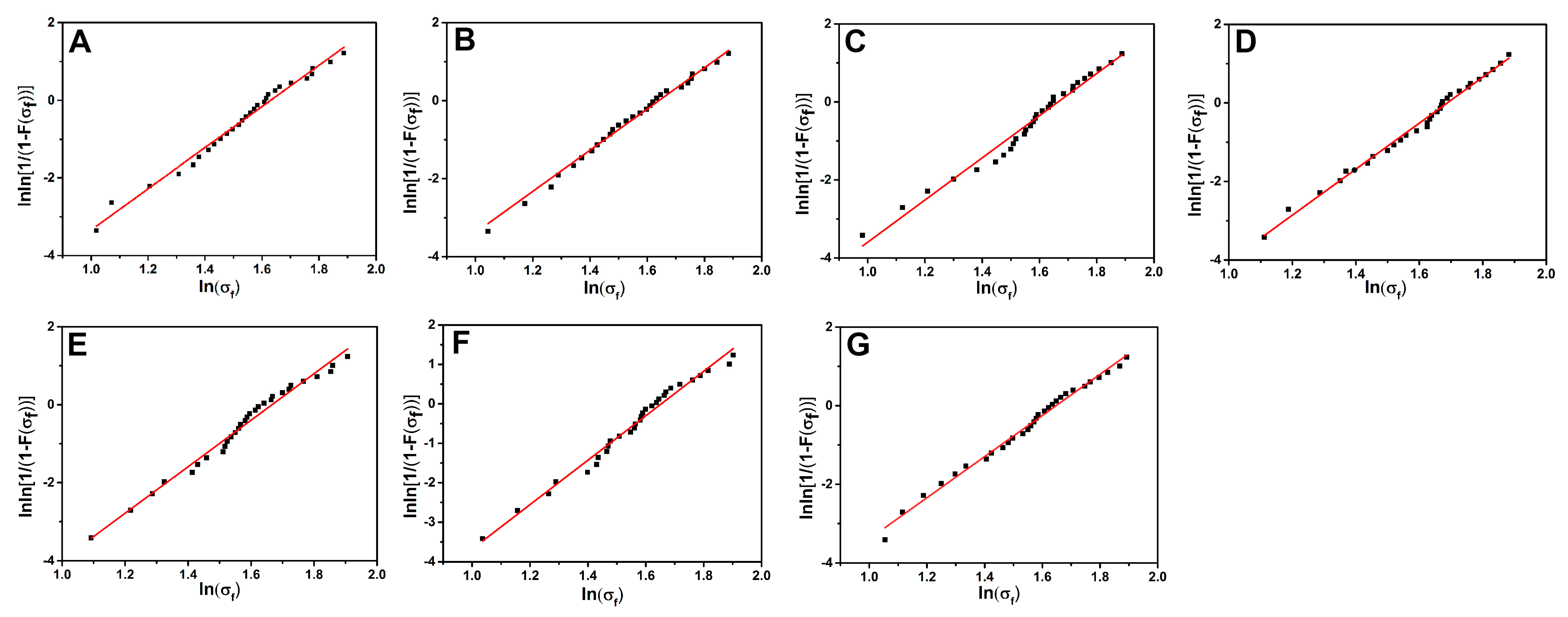
| Samples | m | σ0 | Expectation (GPa) |
|---|---|---|---|
| Untreated CF | 5.31 | 2.44 | 4.71 |
| CF/GO (0.1%) | 5.28 | 2.46 | 4.76 |
| CF/GO (0.3%) | 5.40 | 2.56 | 4.88 |
| CF/GO (0.5%) | 5.85 | 2.77 | 5.03 |
| CF/GO (0.8%) | 5.97 | 2.75 | 4.92 |
| CF/GO (1.0%) | 5.64 | 2.61 | 4.84 |
| CF/GO (0.5%-one step) | 5.24 | 2.46 | 4.78 |
© 2019 by the authors. Licensee MDPI, Basel, Switzerland. This article is an open access article distributed under the terms and conditions of the Creative Commons Attribution (CC BY) license (http://creativecommons.org/licenses/by/4.0/).
Share and Cite
Li, N.; Yang, X.; Bao, F.; Pan, Y.; Wang, C.; Chen, B.; Zong, L.; Liu, C.; Wang, J.; Jian, X. Improved Mechanical Properties of Copoly(Phthalazinone Ether Sulphone)s Composites Reinforced by Multiscale Carbon Fibre/Graphene Oxide Reinforcements: A Step Closer to Industrial Production. Polymers 2019, 11, 237. https://doi.org/10.3390/polym11020237
Li N, Yang X, Bao F, Pan Y, Wang C, Chen B, Zong L, Liu C, Wang J, Jian X. Improved Mechanical Properties of Copoly(Phthalazinone Ether Sulphone)s Composites Reinforced by Multiscale Carbon Fibre/Graphene Oxide Reinforcements: A Step Closer to Industrial Production. Polymers. 2019; 11(2):237. https://doi.org/10.3390/polym11020237
Chicago/Turabian StyleLi, Nan, Xiuxiu Yang, Feng Bao, Yunxing Pan, Chenghao Wang, Bo Chen, Lishuai Zong, Chengde Liu, Jinyan Wang, and Xigao Jian. 2019. "Improved Mechanical Properties of Copoly(Phthalazinone Ether Sulphone)s Composites Reinforced by Multiscale Carbon Fibre/Graphene Oxide Reinforcements: A Step Closer to Industrial Production" Polymers 11, no. 2: 237. https://doi.org/10.3390/polym11020237