Article

Multiscale Interface Effect on Homogeneous Dielectric Structure of ZrO2/Teflon Nanocomposite for Electrowetting Application

1
Guangdong Provincial Key Laboratory of Optical Information Materials and Technology & Institute of Electronic Paper Displays, South China Academy of Advanced Optoelectronics, South China Normal University, Guangzhou 510006, China
2
National Center for International Research on Green Optoelectronics, South China Normal University, Guangzhou 510006, China
3
Department of Chemistry, Faculty of Science and Arts and Promising Centre for Sensors and Electronic Devices, Najran University, Najran 11001, Saudi Arabia
4
Shenzhen Guohua Optoelectronics Tech. Co. Ltd., Shenzhen 518110, China
5
Academy of Shenzhen Guohua Optoelectronics, Shenzhen 518110, China
*
Author to whom correspondence should be addressed.
These authors contributed equally to this work.
Polymers 2018, 10(10), 1119; https://doi.org/10.3390/polym10101119
Submission received: 6 September 2018 / Revised: 28 September 2018 / Accepted: 2 October 2018 / Published: 9 October 2018

Abstract

:
Electrowetting-on-dielectric is a preferred option in practical applications of the electrowetting phenomenon but limited by dielectric and breakdown performances of the dielectric layer. In the present work, a ceramic/polymer nanocomposite as a novel dielectric layer is developed to intensify the overall electrowetting performances by multiscale interface effect. Hereinto, surface fluoro-modified ZrO2 nanoparticles (mZrO2) are dispersed well in AF 1600 matrix to form a mZrO2@AF 1600 nanocomposite. The small addition of mZrO2 improves the dielectric constant of the nanocomposite, and the experimental value is larger than the theoretical value calculated by Maxwell–Garnett model, but fits well with the Rahaman–Khastgir model. The molecular dynamics simulations with the explicit model further verify the interfacial effect. Meanwhile, double contact angle modulation and higher breakdown field strength (Eb) are obtained. For the three-layer sandwich structure, both the top and bottom AF 1600 layer decrease the surface roughness for better electrowetting reproducibility and wider wettability modulation. The Forlani–Minnaja theory related to the empirical relationship between Eb and thickness of dielectric layer fit well with the monolayer structure, but cannot be applied in multi-layer structures. A new relationship is proposed to guide the design of dielectric multi-layers with high breakdown field strength.

Graphical Abstract

1. Introduction

Electrowetting is a microfluidic phenomenon that tunes the surface tension of the liquid droplet on the electrode to enable large and reversible contact angle variations via applied electric field [1,2]. Till now, it has grown into an efficient, versatile, and promising tool to regulate surface wettability of materials and shape of microdroplets, and been applied to electronic paper display [3], microfluidics [4,5], microlenses [6], fiber optics [7], and other electronic fields [8]. In these applications, electrowetting-on-dielectric (EWOD) is a preferred option more than direct electrowetting-on-a-conductor, by which a hydrophobic dielectric layer covers the electrode. High dielectric constant of layer material can strengthen the electrowetting effect in high electric fields. The resultant low surface energy and wettability can make surface microfluids flow expediently [9]. Thus, the dielectric layer is absolutely crucial to the overall performance of EWOD.
Nowadays, more and more inorganic or polymeric materials are used to present dielectric layers [10,11,12]. The former is good at high dielectric constant and low driving voltage, such as SiO2 [13], Si3N4 [14], silicon nanosphere [15], and mesoporous silica [16]. However, their natural defects in film-processing ability seriously hinder the manufacture or electrowetting devices. In particular, high polarity of metal oxides (e.g., ZnO [17,18,19]) even causes incident dielectric lose efficiency. On the contrary, the latter represented as Teflon AF [20,21], Cytop TM [22], Parylene-C [23], polydimethylsiloxane [24], polyimide [25], poly(ethylene terephthalate)/polyethylene [26], and photoresist Su-8 [27], are mainly limited by their relatively low dielectric constant, which is adverse to decreasing driving voltage and avoiding dielectric breakdown [28].
Novel dielectric composite layers for EWOD are further developing, consisting of a top hydrophobic polymer layer and bottom dielectric inorganic/polymeric layer [29,30,31,32]. The layers combine the advantages of both inorganic and polymeric insulating materials but ignore the huge differences in chemical and physical properties between the two materials. Once an electric field is applied, electric charges inevitably concentrate on the surface of hydrophobic layer with much lower dielectric constant than the dielectric layer, accelerating the lose efficiency. In addition, their weak interlayer compatibility will cause layer-to-layer miss-registration, interstice, and even separation.
Addition of ceramic fillers can improve the dielectric constant of the composite. In particular, ferroelectric ceramics with perovskite structure, such as BaTiO3 [33,34], possess intrinsic high dielectric constant up to hundreds and even thousands due to the spontaneous polarization. However, the polarization mainly concentrates upon the interior of fillers. The influence of fillers on the surface of material is still unclear. On the other hand, nanosized fillers are popular for the dielectric film with only sever micrometers; however, nanosized ferroelectric ceramic particles have relatively lower dielectric constant than bulk ceramics due to the phase transition from tetragonal to cubic [35]. For the devices of EWOD, the optical properties should be also considered, limiting the selectivity of type of filler.
As a consequence, we focus on integrating both inorganic and polymeric insulating materials into one highly compatible solution, and preparing the polymer nanocomposite. Within this composite structure, surface fluoro-modified zirconia (mZrO2) nanoparticles with high dielectric constant [36] and high transmittance were hybridized into AF 1600 to form the dielectric nanocomposite. The electrowetting phenomenon of mZrO2/AF 1600 nanocomposite is presented in Scheme 1. Under the electric field, the originally hydrophobic surface changes to be hydrophilic, leading to the decrease of contact angle of droplet on the surface.
Besides the dielectric constant, the breakdown field strength also plays a key role in the performance of dielectric materials. Designing sandwich-structured ceramic/polymer nanocomposites can significantly enhance breakdown field strength [37,38]. However, the relationship between multi-layer structure and breakdown field strength keeps confused. In the present work, sandwich structure is also designed for the enhancement of breakdown field strength, and the regularity is revealed. Meanwhile, the sandwich structure also avoids ionic polarization and alters the surface property.

2. Experimental and Simulated Methods

2.1. Materials

ZrO2 nanoparticles (99.9%; mean size: ~20 nm) and Teflon AF 1600 were purchased from Beijing DK nano technology Co., Ltd. (Beijing, China) and DuPont Company (Wilmington, DE, USA), respectively. 1H,1H,2H,2H-perfluorooctyltriethoxysilane (97%, J&KScientific Ltd., Beijing, China) and prefluorotributylamine (84%, Beijing HWRK Chem Co., Ltd., Beijing, China) were directly used without any further purification. Benzotrifluoride (99%, Adamas Reagent Co., Ltd., Shanghai, China) was dried by vacuum distillation over calcium hydride (CaH2) prior to use. All other regents are of analytic grade.

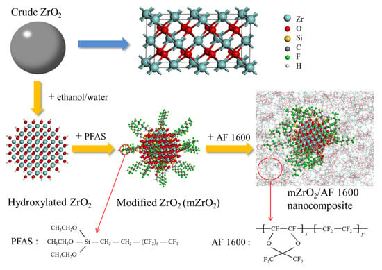
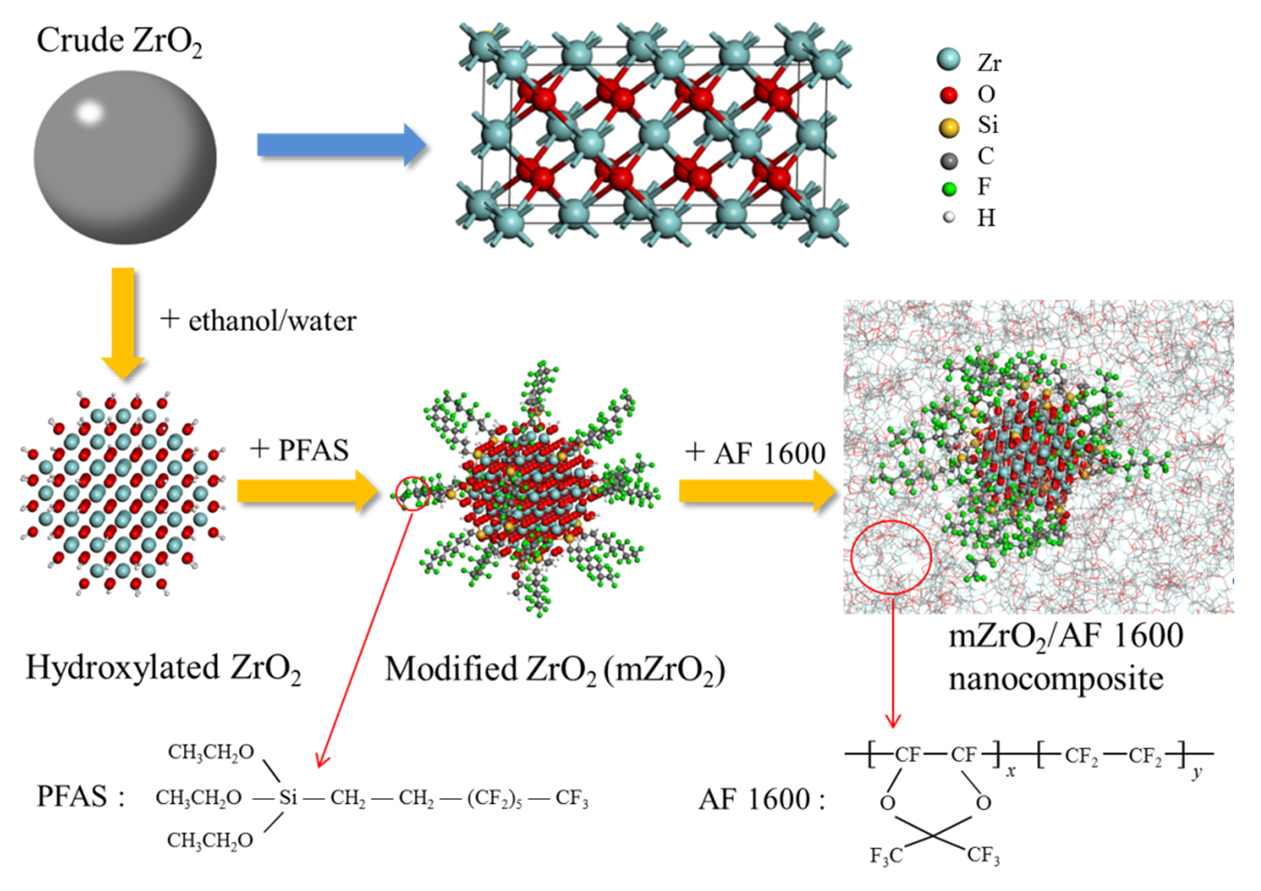
2.2. Surface Modification of ZrO2 Nanoparticles

ZrO2 nanoparticles were modified via surface coupling reaction of fluorinated silane coupling agent (see Scheme 2) as described in the literature [39]. Typically, the crude ZrO2 nanoparticles were rinsed three times with acetone, ethanol and deionized water in ultrasonic cleaner for 10 min, respectively, and then were dried in vacuum at 60 °C for 12 h. In dry argon atmosphere, all these nanoparticles were mixed with 1H,1H,2H,2H-perfluorooctyltriethoxysilane at 1:1.5 mass mole−1 ratio in benzotrifluorideby magnetic stirring at room temperature for 72 h. Finally, the mZrO2 product was rinsed two times with ethanol and acetone, respectively, and then were dried in vacuum at 50 °C for 24 h.

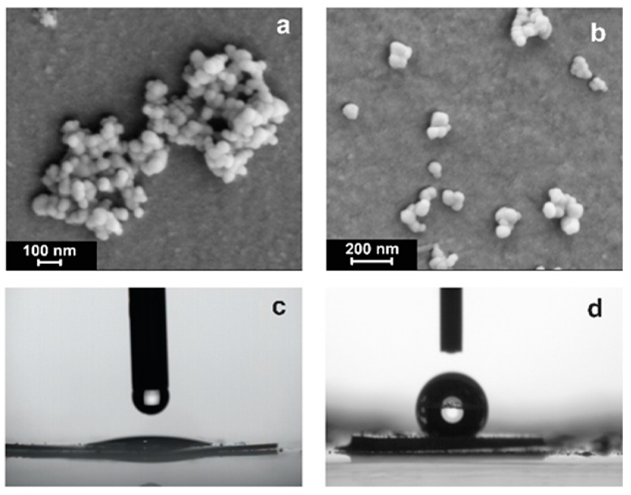
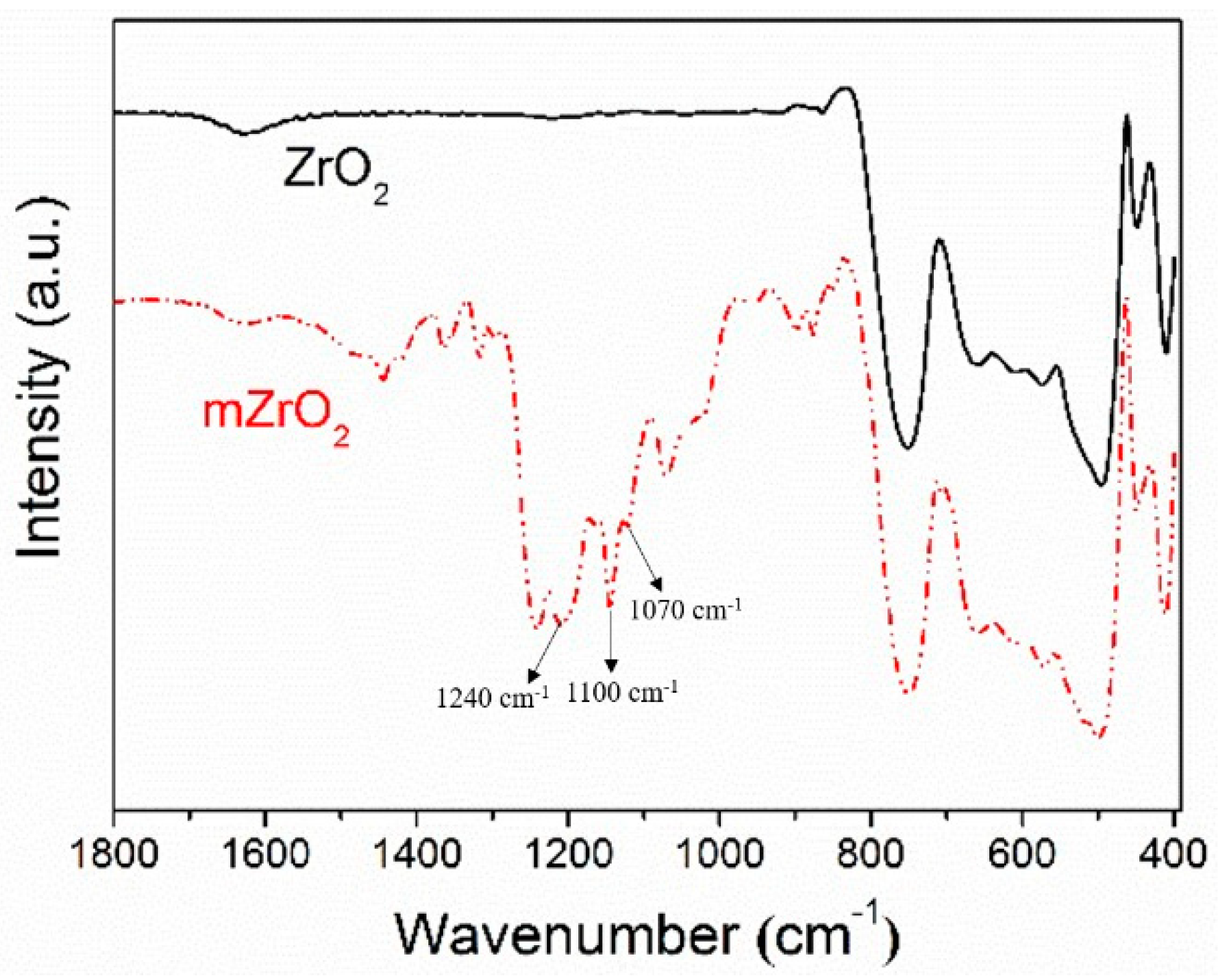
2.3. Characterization of ZrO2 Nanoparticles

Scanning electron microscope (SEM): The morphologies of crude and modified ZrO2 nanoparticles were observed using a ZEISS Ultra 55 (Germany) with the ions energy of 5 kV. Samples were respectively prepared by drying the ethanol solution of crude ZrO2 and the benzotrifluoride solution of mZrO2 with the same concentration of 0.1 mg mL−1 on the clean glass flake adhered to the copper platform.
Static contact angle measurements: Two kinds of ZrO2 nanoparticles were respectively tableted into plates using manual powder tablet press (769YP-15A, KEQI, Tianjin KEQI High & New Technology Corporation, Tianjing, China). Then, a 10 μL droplet of ultrapure water from a hydrophobized needle of a micro-syringe was dropped onto the surface of the plates. The resulting contact angle was recorded by a contact angle meter (JC2000C, POWEREACH, Shanghai, China), and measured by an image analysis software (DSA10Mk2 drop shape analysis system, Krüss Hamburg, Germany).
Fourier infrared spectrometer (FT-IR): The surface variation between the crude and modified ZrO2 nanoparticles was identified by FT-IR (Tensor 27, Bruker, Karlsruhe, Germany) in a spectral range of 4000–400 cm−1 with a resolution of 2 cm−1 using a potassium bromide plate.

2.4. Compatibility Test of ZrO2 with AF 1600

The compatibility tests were performed using differential scanning calorimetry (DSC; DSC1, METTLER TOLEDO, Zurich, Switzerland) within a temperature range of 25 to 200 °C at a heating rate of 10 °C min−1 under nitrogen gas (flow rate: 10 mL min−1).

2.5. Preparation on mZrO2@AF 1600 Layer

Typically, a determined weight of mZrO2 nanoparticles was uniformly dispersed in prefluorotributylamine solution of AF 1600 (3.7 wt %) by high intensity ultrasound (VCX150PB, SONICS, Newtown, PA, USA). Afterwards, the mixture was coated on the surface of indium tin oxide (ITO) glass using a spin coater (KW-4A, Institute of Microelectronics of the Chinese Academy of Sciences, Beijing, China) with a fixed rotating speed of 1200 rpm. Finally, the coated slide was dried in a vacuum at 100 °C for 2 h to remove the residual organic solvent thoroughly. Pure AF 1600 layer, double-, and three-layer structures were fabricated by repeating the same process.

2.6. Characterization of mZrO2@AF 1600 Layer

Capacitor measurements: The capacitor measurements were performed by inputting signal of alternating current (AC; 0.5 V, 1 kHz) using an impedance analyzer (6500B, WAYNE KERR, London, UK). The positive pole of the impedance analyzer was attached to the platinum (Pt) probe that was inserted into a 10 μL droplet of 0.1 M sodium chloride (NaCl) aqueous solution on the layer surface, and the negative pole was attached to the ITO side of the substrate. The real-time capacity values were displayed on the screen of the impedance analyzer until remaining constant.
Surface profile analysis: The layer thickness, surface topography and roughness were measured by three-dimensional (3D) surface profiler (DCM8, Leica, Biberach, Germany) with a 50-fold objective.
Electrowetting test: The electrowetting tests were performed using digital regulated direct current (DC) power supply (CE0400010T, Earthworm Electronics, Shanghai, China) (see Scheme 1) with the same pole connection mentioned above in the capacitor measurements. As the applied voltage increased from 0 V to the breakdown voltage (Vb) value (see the following Vb measurements) with the step of 5 V, the real-time change of NaCl droplet was recorded by contact angle meter and analyzed using an image analysis software.
Dynamic contact angle measurements: Typically, a 10 μL droplet of ultrapure water from the hydrophobized needle of a micro-syringe was dropped onto the layer surface. During the movement of the objective table, the resulting advancing angle, and receding angle was recorded by contact angle meter, and measured by image analysis software.
Vb measurements: The Vb measurements were performed using a digital regulated DC power supply with the same pole connection mentioned above in the capacitor measurements. Along with increasing DC voltage, the real-time changes of NaCl droplet were observed by contact angle meter till a few tiny bubbles generated in the droplet. At this time, the applied DC voltage is viewed as Vb. The final Vb is the average of at least five measured values with mean square error less than 5 V.

2.7. Simulated Method

Scheme 2 shows the structure of Teflon AF. For the AF 1600, the ratio of x/y is 13/7. In our models, we built the AF 1600 molecules with x = 13 and y = 7. There were 100 molecules in the pure AF 1600 system. For the mZrO2/AF 1600 nanocomposite, the spherical ZrO2 (containing 87 Zr atoms and 174 O atoms) with a radius equaling to approximately 8 nm was built, and there were 100 AF 1600 molecules. The ZrO2 particle was grafted by 20 PFAS molecules. The simulation was run at 500 K for 0.2 ns in the NPT ensemble to obtain sufficiently relaxed structures. Then, the system was run at 300 K in the NPT ensemble for 0.2 ns to obtain an equilibrated density. Finally, the simulation was run at 300 K in the NVT ensemble for 0.2 ns and the following 0.3 ns data were recorded for analysis.

3. Results and Discussion

As well-known, homogeneous nature is the prerequisite to optimize the overall performance of polymer composite, which is mainly determined by matrix compatibility. However, fluoropolymers represented as Teflon series is generally incompatible with other common materials. Therefore, “surface ligand engineering” is often introduced to improve the compatibility between filler and framework material [40,41]. Here we employed the coupling of 1H,1H,2H,2H-perfluorooctyltriethoxysilane (PFAS) to the hydroxylated surface of ZrO2 nanoparticles to achieve surface fluorination (see Scheme 2).
In general, interfacial incompatibility exists due to the hydrophilicity of filler surface and hydrophobicity of polymer, leading to aggregation of nanoparticles [42,43]. Naturally, the introduced fluorocarbon chains [44] with a similar component as matrix chains will weaken the interaction within ZrO2 nanoparticles against aggregation, just like what appears in Figure 1b. Here, there is no big aggregation of fluorosilane-modified nanoparticles (mZrO2), opposite to what the crude ZrO2 ones did in Figure 1a. In particular, the static water contact angle rises from less than 10° to 135°, i.e., the superficial nature of the nanoparticles alters from hydrophilic to hydrophobic (see Figure 1c,d). It indicates that surface modification greatly changes the wettability of ZrO2. Moreover, the C–F stretching vibration (1240–1100 cm−1), and Si–O antisymmetric stretching vibration (1070 cm−1) in the FT-IR spectra (see Figure 2) also provide convincing evidence on surface fluorination.
Meanwhile, mZrO2 nanoparticles have a good compatibility with AF 1600 substrate. In the temperature transformation diagrams (Figure 3), crude AF 1600 exhibits two endothermic peaks, but only one peak after hybridization. Both glass transition temperature (Tg) and the specific heat capacity (ΔCp) fall, along with the introduction of ZrO2 and mZrO2 nanoparticles, respectively. Obviously, ZrO2 particles with good thermal conductivity and high specific surface area can conduct heat rapidly and inhibit the intertwining of polymer molecular chains effectively as a result of the “easier” phase transition. Additionally, these surface-fluorinated mZrO2 particles further decrease Tg and ΔCp of nanocomposites, which only attributes to their better compatibility with AF 1600 than ZrO2’s. As previously mentioned, good matrix compatibility can lower the interfacial difference between nanofiller and framework material to make the nanocomposites more homogeneous. It will surely help tuning, even optimizing, some key functionalities for electrowetting intensification.
In the EWOD device, the dielectric layer does perform as a capacitor blocking electron and hold large electrostatic energy. Once an electric potential is applied between the top and bottom electrode, an electric double layer will appear spontaneously both at the solid–liquid interface and the solid–solid interface to cause the originally hydrophobic layer surface to be hydrophilic. Hereinto, the ability of charge accumulation, or in a sense, the surface wettability variation, depends entirely on dielectric constant (ε) of the resulting insulating layer. In general, ε is obtained by calculation according to the following equation:
C = ε ε 0 / t
where C is the capacitance per unit area, t is the thickness of the capacitor (i.e., dielectric layer between droplet and a solid electrode), ε0 is the permittivity of free space which is approximately 8.85 × 10⁻¹² F m−1.
Here, the obtained initial value of pure AF 1600 is only 1.54 that agrees with few measured data [45], but not with the general value (1.93). Just as shown in Figure 4, we investigated the relationship between ε value of mZrO2@AF 1600 nanocomposite with mZrO2 concentration in detail.
The ε equaling to 2.02 at low volume fraction of mZrO2 (5.35 vol %, i.e., 15 wt %) is higher than the theoretical value (1.75) calculated by Maxwell–Garnett model [46]:
ε    =    ε m    2 ε m + ε f + 2 φ ( ε f ε m ) 2 ε m + ε f φ ( ε f ε m )
where φ represents the volume fraction of mZrO2 in AF 1600 matrix, ε, εm and εf denote the dielectric constant of the mZrO2@AF 1600 nanocomposite, AF 1600 matrix and mZrO2 filler, respectively. The inconsistence between the theoretical and experimental values of ε maybe attribute to the neglecting of interfacial polarization in Maxwell–Garnett model.
On the contrary, the Rahaman–Khastgir model involving the effect of interfacial polarization fits well with experimental data [47]:
log ε = log ε f + log ε m log ε f e φ M log F
where F is the measurement frequency (i.e., 1 kHz), and M is the morphological factor/fitting parameter, depending on shape, size, dispersion, distribution, and permittivity of particulate inclusion and host medium. It means that the improvement of dielectric constant at low mZrO2 content attributes to the interfacial polarization.
For further understanding the interfacial effect of the composite, we adopted the molecular dynamics simulations with explicit atom model. Unlike the Tanaka’s multi-core model [48] of polymer nanocomposite (including the bonded layer, bound layer and loose layer), there is no bound layer in the mZrO2@AF 1600 nanocomposite. The density of the matrix of composite is lower than that of pure AF 1600 (1.98 g cm−3 based on the MD’s result), as shown in Figure 5. On the other hand, since the PFAS molecules do not cover the ZrO2 particle, the bonded layer and the loose layer are overlapped. The interfacial region comprising of a bonded/loose layer possesses an ultralow density. Low density indicates high free volume where the orientation of dipole moment can be rearranged easily under the electric field. In other words, the orientational polarization in the interfacial region is greater than that in the matrix. Therefore, the poor packing would account for faster segmental and chain dynamics, i.e., the improvement of the dielectric constant [49].
Given the above analyses, 5.35 vol % mZrO2@AF 1600 nanocomposite was chosen as the unique target of dielectric material to fabricate different dielectric layer structures in follow-up research. The surface morphology of dielectric film mainly decides the response rate and the reversibility of a droplet on the film under the applied electric field. Addition of inorganic fillers inevitably increases the surface roughness of organic polymer film. In Figure 6, the resulting mZrO2@AF 1600 film is almost as smooth as the AF 1600 one. Actually, its surface roughness (Ra = 3.49 nm) is only slightly higher than the one of the latter (Ra = 3.16 nm). Low surface roughness is attributed to low concentration and surface modification of inorganic fillers.
After analyzing the dielectric constant and the surface roughness which are the crucial factors for the wettability, the contact angles are investigated. Figure 7a,c,d shows that, although the initial contact angle of the single mZrO2@AF 1600 layer (103° ± 1.5°) is lower than that of the AF 1600 layer (114° ± 2.2°), its variation range of contact angles under applied DC electric field (17.8°) exceeds two times the AF 1600 one (8.2°). Very clearly, the larger contact angle modulation is based on higher dielectric constant of mZrO2@AF 1600 nanocomposite according to the Young–Lippmann equation:
cos θ v = cos θ 0 + 1 2 γ ε     ε 0    U 2
where θ0 is the initial contact angle of droplet, θv is the contact angle under applied electric potential (U), γ is the surface tension between two immiscible fluids. However, its mildly wavy surface may bring about the drop of initial contact angle (see Figure 7a) and the rise of contact angle hysteresis (see Figure 7b). As the mZrO2 content rises, the dielectric layer becomes rougher to increase contact angle hysteresis against EWOD. Typically, the retreat ability and reproducibility of surface droplet will be weakened.
It is also inevitable that some mZrO2 nanoparticles in the AF 1600 matrix next to the electrode substrate will be partially polarized by ionization. Therefore, we further developed a three-layer sandwich structure with a top and bottom pure AF 1600 layer, and a mZrO2@AF 1600 interlayer, to make up for the above defects. As presented in Figure 7e, if the voltage is on state, the difference of surface contact angle of the sandwich film (20.8°) is higher than that of the single AF 1600 layer (8.2°). Once the voltage changes to be off state, the difference between the initial contact angle and the recovered contact angle of the former is only 5.4°. Meanwhile, its driving-recovery process can work very rapidly and repeatedly. These results indicate that the sandwich structure containing mZrO2@AF 1600 layer possesses better electrowetting reversibility and wider wettability modulation. Apparently, the enhanced electrowetting reversibility is attributed to the reduced surface roughness based on the top AF 1600 layer, and the widened wettability variation is attributed to the increased dielectric constant based on the mZrO2@AF 1600 nanocomposite interlayer.
Besides surface wettability, both breakdown voltage and corresponding breakdown field strength (Eb) are considered as important evaluation indexes on the dielectric layer in EWOD. Based on the Young–Lippmann equation (Equation (4)), the Eb has a greater effect than ε on the contact angle modulation. Besides the nature of material, the thickness of the film has obvious influence on the breakdown field strength. According to the Forlani–Minnaja theory [50], the empirical relationship between Eb and thickness (t) appears as:
E b t k
where k is determined by the cooperation of lattice energy state, electron energy state and electron–lattice interaction. Therefore, we fabricated a series of monolayer mZrO2@AF 1600 and AF 1600 films with thickness varying from 0.12 to 1.70 μm for Eb analysis. As shown in Figure 8a, the mZrO2@AF 1600 layer exhibits higher Eb value than AF 1600’s at the same thickness, similar to Dawber’s [51] and Huang’s [52] works on other amorphous solids. Obviously, it behaves with a higher proposed coefficient (79.53) and much closer to an ideal reciprocal relationship to t (k = −0.98). Here, the higher dielectric constant of the uniform nanocomposites originated from lack of ZrO2 aggregation plays an important role at low turning concentration.
What is the function of the bottom AF 1600 layer? Besides the surface roughness, we also measured and analyzed the breakdown performances of double-layer composite structure and three-layer sandwich structure presented in Figure 8b,c. Obviously, the double-layer structure approximately obeys the basic principle of Eb that decreases followed by increasing layer thickness (see Figure 8a), but the sandwich structure does not, as shown in Figure 8b. In Figure 8c, the best fitting curves reveal that, Eb of the sandwich structure mainly depends on the determined thickness of both the mZrO2@AF 1600 interlayer and the bottom AF 1600 layer, and may be not affected by the top AF 1600 layer. Particularly, according to the fitting equation, high Eb is very possible to be obtained by rising tn and falling tb simultaneously. Additionally, the higher volume fraction of the mZrO2@AF 1600 interlayer (φn) and the resulting higher dielectric index (ε) also does. On the contrary, the opposite laws of layer thickness with ε and Eb (see Figure 8b,c) do not allow the double-layer composite structure to keep both ε and Eb gentle at a relatively high level for electrowetting intensification. Here, it is found that the bottom AF 1600 layer is of decisive importance in the three-layer sandwich structure. Just as mentioned previously, inorganic metal oxide with high polarity is very easily ionically polarized as a result of dielectric lose efficiency, but the bottom AF 1600 layer prevents its occurrence.

4. Conclusions

In conclusion, in order to optimize the dielectric performances of the insulating layer in EWOD, we combined theoretical models, molecular dynamics simulations, and experimental methods. In the experiments, we fabricated a polymer nanocomposite that combines the advantages of inorganic materials, fluoropolymer, and organic/inorganic composite structure. Here, the interfacial effect plays an important and conclusive role in outstanding electrowetting intensification. Firstly, surface-fluorinated modification of ZrO2 nanoparticles improves the compatibility of nanoparticles and the AF 1600 matrix to increase the dielectric constant of mZrO2@AF 1600 nanocomposite (2.02, about 31% higher than pure AF 1600’s) at low content, followed by double contact angle modulation and higher breakdown field strength. The small addition of mZrO2 improves the dielectric constant of the nanocomposite, and the experimental value is larger than the theoretical value calculated by the Maxwell–Garnett model, but fits well with the Rahaman–Khastgir model. The molecular dynamics simulations with the explicit model further verifies the interfacial effect.
Its only weakness is that the nanoparticle hybridization surely generates worse contact angle hysteresis. In the sandwich structure, both the top and bottom AF 1600 layer may weaken the bumpy medial mZrO2@AF 1600 layer for better electrowetting reversibility and wider wettability modulation. At the same time, the bottom layer isolated those ZrO2 nanoparticles from the electrode against ionic polarization. Marvelously, this structure can change the relationship between volume fraction of mZrO2@AF 1600 layer and Eb, which will make more potential spaces for overall enhancements on both dielectric and breakdown performances. Multiscale interface effects based on the surface modification of nanoparticles and design of sandwich structure are revealed. It is anticipated to provide a facile, effective and practical strategy for enhancing the electrowetting performances of EWOD.

Author Contributions

H.L. conceived and designed the experiments; J.H., J.L. and W.D. performed the experiments; Y.F. and J.L. performed the simulations and analyzed the data; L.S., Y.W., A.U., and B.T. provided some suggestions for this project; H.L., Y.F., and J.H. wrote the manuscript; J.L. and G.Z. helped us to revise the manuscript. All authors critically reviewed the manuscript.

Funding

This work was financially supported by the National Key Research and Development Program of China (No. 2016YFB0401501), National Natural Science Foundation of China (No. 51703070), Key Cultivation Project of Basic Research of Guangdong Natural Science Foundation (No. 2014A030308013), Guangdong Provincial Key Laboratory of Optical Information Materials and Technology (No. 2017B030301007), MOE International Laboratory for Optical Information Technologies and the 111 Project, and Guangzhou Municipal Key Laboratory of Electronic Paper Displays Materials and Devices (No. 201705030007).

Acknowledgments

This work was technically supported by the Chemcloudcomputing of the Beijing University of Chemical Technology.

Conflicts of Interest

The authors declare no conflict of interest.

References

  1. Mugele, F.; Baret, J.-C. Electrowetting: from basics to applications. J. Phys. Condens. Matter 2005, 17, R705–R774. [Google Scholar] [CrossRef] [Green Version]
  2. Xia, Y.; Chen, J.; Zhu, Z.; Zhang, Q.; Yang, H.; Wang, Q. Significantly enhanced dielectric and hydrophobic properties of SiO2@MgO/PMMA composite films. RSC Adv. 2018, 8, 4032–4038. [Google Scholar] [CrossRef]
  3. Hayes, R.A.; Feenstra, B.J. Video-speed electronic paper based on electrowetting. Nature 2003, 425, 383–385. [Google Scholar] [CrossRef] [PubMed]
  4. Kong, T.; Brien, R.; Njus, Z.; Kalwa, U.; Pandey, S. Motorized actuation system to perform droplet operations on printed plastic sheets. Lab Chip. 2016, 16, 1861–1872. [Google Scholar] [CrossRef] [PubMed]
  5. Gao, J.; Chen, T.; Dong, C.; Jia, Y.; Mak, P.I.; Vai, M.I.; Rui, P.M. Adhesion promoter for a multi-dielectric-layer on a digital microfluidic chip. RSC Adv. 2015, 5, 48626–48630. [Google Scholar] [CrossRef] [Green Version]
  6. Terrab, S.; Watson, A.M.; Roath, C.; Gopinath, J.T.; Bright, V.M. Adaptive electrowetting lens-prism element. Opt. Express. 2015, 23, 25838–25845. [Google Scholar] [CrossRef] [PubMed]
  7. Ozbay, B.N.; Losacco, J.T.; Cormack, R.; Weir, R.; Bright, V.M.; Gopinath, J.T.; Restrepo, D.; Gibson, E.A. Miniaturized fiber-coupled confocal fluorescence microscope with an electrowetting variable focus lens using no moving parts. Opt. Lett. 2015, 40, 2553–2556. [Google Scholar] [CrossRef] [PubMed]
  8. Khan, I.; Castelletto, S.; Rosengarten, G. Fabrication of solar beam steering electrowetting devices—present status and future prospects. J. Phys. D Appl. Phys. 2017, 50, 403001. [Google Scholar] [CrossRef] [Green Version]
  9. Nelson, W.C.; Kim, C.-J.C. Droplet Actuation by Electrowetting-on-Dielectric (EWOD): A Review. J. Adhes. Sci. Technol. 2012, 26, 1747–1771. [Google Scholar] [CrossRef]
  10. Liu, H.; Dharmatilleke, S.; Maurya, D.K.; Tay, A.A.O. Dielectric materials for electrowetting-on-dielectric actuation. Microsyst. Technol. 2010, 16, 449–460. [Google Scholar] [CrossRef]
  11. Li, Z.; Haigh, A.; Soutis, C.; Gibson, A.; Sloan, R. Dielectric constant of a three-dimensional woven glass fibre composite: Analysis and measurement. Compos. Struct. 2017, 180, 853–861. [Google Scholar] [CrossRef]
  12. Bormashenko, E.; Pogreb, R.; Bormashenko, Y.; Aharoni, H.; Shulzinger, E.; Grinev, R.; Rozenman, D.; Rozenman, Z. Progress in low voltage reversible electrowetting with lubricated polymer honeycomb substrates. RSC Adv. 2015, 5, 32491–32496. [Google Scholar] [CrossRef]
  13. Lapierre, F.; Brunet, P.; Coffinier, Y.; Thomy, V.; Blossey, R.; Boukherroub, R. Simulations of theoretically informed coarse grain models of polymeric systems. Faraday Discuss. 2010, 146, 125–139. [Google Scholar] [CrossRef] [PubMed]
  14. Shen, H.H.; Chung, L.Y.; Yao, D.J. Improving the dielectric properties of an electrowetting-on-dielectric microfluidic device with a low-pressure chemical vapor deposited Si3N4 dielectric layer. Biomicrofluidics 2015, 9, 022403. [Google Scholar] [CrossRef] [PubMed] [Green Version]
  15. Mats, L.; Bramwell, A.; Dupont, J.; Liu, G.; Oleschuk, R. Electrowetting on superhydrophobic natural (Colocasia) and synthetic surfaces based upon fluorinated silica nanoparticles. Microelectron. Eng. 2015, 148, 91–97. [Google Scholar] [CrossRef]
  16. Ghazzal, M.N.; Joseph, M.; Kebaili, H.; De Coninck, J.; Gaigneaux, E.M. Tuning the selectivity and sensitivity of mesoporous dielectric multilayers by modifiying the hydrophobic–hydrophilic balance of the silica layer. J. Mater. Chem. 2012, 22, 22526–22532. [Google Scholar] [CrossRef]
  17. Kudr, J.; Richtera, L.; Nejdl, L.; Xhaxhiu, K.; Vitek, P.; Rutkay-Nedecky, B.; Hynek, D.; Kopel, P.; Adam, V.; Kizek, R. Improved electrochemical detection of zinc ions using electrode modified with electrochemically reduced graphene oxide. Materials 2016, 9, 31. [Google Scholar] [CrossRef] [PubMed]
  18. Wu, J.; Xia, J.; Lei, W.; Wang, B.P. Electrowetting on ZnO nanowires. Appl. Phys. A 2010, 99, 931–934. [Google Scholar] [CrossRef]
  19. Papadopoulou, E.L.; Pagkozidis, A.; Barberoglou, M.; Fotakis, C.; Stratakis, E. Electrowetting properties of ZnO and TiO2 nanostructured thin films. J. Phys. Chem. C 2010, 114, 10249–10253. [Google Scholar] [CrossRef]
  20. Bienia, M.; Catherine Quilliet, A.; Vallade, M. Modification of drop shape controlled by electrowetting. Langmuir 2003, 19, 9328–9333. [Google Scholar] [CrossRef]
  21. Welters, W.J.J.; Fokkink, L.G.J. Fast electrically switchable capillary effects. Langmuir 1998, 14, 1535–1538. [Google Scholar] [CrossRef]
  22. Banpurkar, A.; Sawane, Y.B.; Wadhai, S.M.; Murade, C.; Siretanu, I.; van den Ende, D.; Mugele, F. Using one halogen bond to change the nature of a second bond in ternary complexes with P⋯Cl and F⋯Cl halogen bonds. Faraday Discuss. 2017, 199, 29–47. [Google Scholar] [CrossRef] [PubMed]
  23. Burger, B.; Rabot, R. Design of low hysteresis electrowetting systems in non-aqueous media by the addition of low HLB amphiphilic compounds. Colloids Surfaces A 2016, 510, 129–134. [Google Scholar] [CrossRef]
  24. Tamaddoni, N.; Taylor, G.; Hepburn, T.; Michael, K.S.; Sarles, S.A. Reversible, voltage-activated formation of biomimetic membranes between triblock copolymer-coated aqueous droplets in good solvents. Soft Matter 2016, 12, 5096–5109. [Google Scholar] [CrossRef] [PubMed]
  25. Kopp, D.; Zappe, H. Tubular astigmatism-tunable fluidic lens. Opt. Lett. 2016, 41, 2735–2738. [Google Scholar] [CrossRef] [PubMed]
  26. Xiao, K.; Zhou, Y.; Kong, X.Y.; Xie, G.; Li, P.; Zhang, Z.; Wen, L.; Jiang, L. Electrostatic-charge- and Electric-field-induced smart gating for water transportation. ACS Nano 2016, 10, 9703–9709. [Google Scholar] [CrossRef] [PubMed]
  27. Kumar, V.; Sharma, N.N. SU-8 as hydrophobic and dielectric thin film in electrowetting-on-dielectric based microfluidics device. J. Nanotech. 2012, 312784. [Google Scholar] [CrossRef]
  28. Facchetti, A.M.; Yoon, H.; Marks, T.J. Gate Dielectrics for organic field-effect transistors: new opportunities for organic electronics. Adv. Mater. 2005, 17, 1705–1725. [Google Scholar] [CrossRef]
  29. Koumoulos, E.P.; Charitidis, C.A.; Papageorgiou, D.P.; Papathanasiou, AG.; Boudouvis, A.G. Nanomechanical and nanotribological properties of hydrophobic fluorocarbon dielectric coating on tetraethoxysilane for electrowetting applications. Surf. Coat. Technol. 2012, 206, 3823–3831. [Google Scholar] [CrossRef]
  30. Khodayari, M.; Hahne, B.; Crane, N.B.; Volinsky, A.A. Floating electrode electrowetting on hydrophobic dielectric with an SiO2 layer. Appl. Phys. Lett. 2013, 102, 192907. [Google Scholar] [CrossRef]
  31. Schultz, A.; Chevalliot, S.; Kuiper, S.; Heikenfeld, J. Detailed analysis of defect reduction in electrowetting dielectrics through a two-layer ‘barrier’ approach. Thin Solid Films 2013, 534, 348–355. [Google Scholar] [CrossRef]
  32. Jiang, C.; Ma, H.; Hasko, D.G.; Nathan, A. Influence of polarization on contact angle saturation during electrowetting. Appl. Phys. Lett. 2016, 109, 211601. [Google Scholar] [CrossRef]
  33. Zhang, X.; Shen, Y.; Zhang, Q.; Gu, L.; Hu, Y.; Du, J.; Lin, Y.; Nan, C.W. Ultrahigh Energy Density of Polymer Nanocomposites Containing BaTiO3@TiO2 Nanofibers by Atomic-Scale Interface Engineering. Adv. Mater. 2015, 27, 819. [Google Scholar] [CrossRef] [PubMed]
  34. Dang, Z.M.; Yuan, J.K.; Yao, S.H.; Liao, R.J. Flexible nanodielectric materials with high permittivity for power energy storage. Adv. Mater. 2013, 25, 6334–6365. [Google Scholar] [CrossRef] [PubMed]
  35. Zhang, X.; Li, B.-W.; Dong, L.; Liu, H.; Chen, W.; Shen, Y.; Nan, C.-W. Superior Energy Storage Performances of Polymer Nanocomposites via Modification of Filler/Polymer Interfaces. Adv. Mater. Interf. 2018, 5, 1800096. [Google Scholar] [CrossRef]
  36. Beaulieu, M.R.; Baral, J.K.; Hendricks, N.R.; Tang, Y.; Briseno, A.L.; Watkins, J.J. Solution processable high dielectric constant nanocomposites based on ZrO2 nanoparticles for flexible organic transistors. ACS Appl. Mater. Interfaces 2013, 5, 13096–13103. [Google Scholar] [CrossRef] [PubMed]
  37. Hu, P.; Shen, Y.; Guan, Y.; Zhang, X.; Lin, Y.; Zhang, Q.; Nan, C.W. Topological-Structure Modulated Polymer Nanocomposites Exhibiting Highly Enhanced Dielectric Strength and Energy Density. Adv. Funct. Mater. 2014, 24, 3172–3178. [Google Scholar] [CrossRef]
  38. Wang, Y.; Cui, J.; Wang, L.; Yuan, Q.; Niu, Y.; Chen, J.; Wang, Q.; Wang, H. Compositional tailoring effect on electric field distribution for significantly enhanced breakdown strength and restrained conductive loss in sandwich-structured ceramic/polymer nanocomposites. J. Mater. Chem. A 2017, 5, 4710–4718. [Google Scholar] [CrossRef]
  39. Kujawa, J.; Cerneaux, S.; Kujawski, W. Characterization of the surface modification process of Al2O3, TiO2 and ZrO2 powders by PFAS molecules. Colloids Surfaces A 2014, 447, 14–22. [Google Scholar] [CrossRef]
  40. Li, Y.; Krentz, T.M.; Wang, L.; Benicewicz, B.C.; Schadler, L.S. Ligand engineering of polymer nanocomposites: From the simple to the complex. ACS Appl. Mater. Interfaces 2014, 6, 6005–6021. [Google Scholar] [CrossRef] [PubMed]
  41. Özden-Yenigün, E.; Bilge, K.; Sünbüloğlu, E.; Bozdağ, E.; Papila, M. High strain rate response of nanofiber interlayered structural composites. Compos. Struct. 2017, 168, 47–55. [Google Scholar] [CrossRef]
  42. Kango, S.; Kalia, S.; Celli, A.; Njuguna, J.; Habibi, Y.; Kumar, R. Surface modification of inorganic nanoparticles for development of organic–inorganic nanocomposites—A review. Prog. Polym. Sci. 2013, 38, 1232–1261. [Google Scholar] [CrossRef]
  43. Iijima, M.; Kamiya, H. Surface modification for improving the stability of nanoparticles in liquid media. KONA Powder Part. J. 2009, 27, 119–129. [Google Scholar] [CrossRef]
  44. Lemal, D.M. Perspective on fluorocarbon chemistry. J. Org. Chem. 2004, 69, 1–11. [Google Scholar] [CrossRef] [PubMed]
  45. Ding, S.J.; Wang, P.F.; Zhang, D.W.; Wang, J.T.; Wei, W.L. A novel structural amorphous fluoropolymer film with an ultra-low dielectric constant. Mater. Lett. 2001, 49, 154–159. [Google Scholar] [CrossRef]
  46. Maxwell-Garnett, J.C. Colours in metal glasses and in metallic films. Philos. Trans. R. Soc. A 1904, 203, 385–420. [Google Scholar] [CrossRef]
  47. Rahaman, M.; Chaki, T.K.; Khastgir, D. Consideration of interface polarization in the modeling of dielectric property for ethylene vinyl acetate (EVA)/polyaniline conductive composites prepared through in-situ polymerization of aniline in EVA matrix. Eur. Polym. J. 2012, 48, 1241–1248. [Google Scholar] [CrossRef]
  48. Tanaka, T.; Kozako, M.; Fuse, N.; Ohki, Y. Proposal of a multi-core model for polymer nanocomposite dielectrics. IEEE Trans. Dielect. Electr. Insul. 2005, 12, 669–681. [Google Scholar] [CrossRef]
  49. Casalini, R.; Roland, C.M. Local and global dynamics in polypropylene glycol/silica composites. Macromolecules 2016, 49, 3919–3924. [Google Scholar] [CrossRef]
  50. Forlani, F.; Minnaja, N. Thickness influence in breakdown phenomena of thin dielectric films. Phys. Status Solidi 1964, 4, 311–324. [Google Scholar] [CrossRef]
  51. Dawber, M.; Rabe, K.M.; Scott, J.F. Critical adsorption at the free surface of a smectic liquid crystal possessing a second-order phase transition. Rev. Mod. Phys. 2005, 77, 1083–1130. [Google Scholar] [CrossRef]
  52. Huang, J.; Shian, S.; Diebold, R.M.; Suo, Z.; Clarke, D.R. The thickness and stretch dependence of the electrical breakdown strength of an acrylic dielectric elastomer. Appl. Phys. Lett. 2012, 101, 122905. [Google Scholar] [CrossRef] [Green Version]
Scheme 1. Schematic of electrowetting phenomenon of mZrO2/AF 1600 nanocomposite.
Polymers 10 01119 sch001
Scheme 2. Schematic of preparation of mZrO2/AF 1600 nanocomposite.
Polymers 10 01119 sch002
Figure 1. SEM and static water contact angle images of ZrO2 nanoparticles before (a and c) and after surface fluorination (b and d), respectively.
Polymers 10 01119 g001
Figure 2. FT-IR spectra of crude zirconia (ZrO2) and surface fluoro-modified zirconia (mZrO2). The related peaks listed below: 1240–1100 cm–1 (νs, C–F on PFAS) and 1070 cm–1 (νas, Si–O linked with ZrO2).
Polymers 10 01119 g002
Figure 3. DSC heating curves of AF 1600, ZrO2@AF 1600 and mZrO2@AF 1600 samples (ΔCp: the specific heat capacity).
Polymers 10 01119 g003
Figure 4. Experimental and theoretical dielectric constants (ε) of mZrO2@AF 1600 nanocomposite films under different mZrO2 volume fractions (φ).
Polymers 10 01119 g004
Figure 5. Density distribution around the center of ZrO2 in the mZrO2@AF 1600 nanocomposite. The content of mZrO2 is 5 wt %, and the radius of mZrO2 is approximately 8 nm.
Polymers 10 01119 g005
Figure 6. 3D surface topography of AF 1600 (a) and mZrO2@AF 1600 with 5.35 vol % mZrO2 (b) monolayer film under 50-fold objective.
Polymers 10 01119 g006
Figure 7. (a) Contact angles of the two films under applied DC electric field; (b) Contact angle hysteresis of the nanocomposite film with different mZrO2 concentrations; (c) Contact angle images of the monolayer AF 1600 and (d) mZrO2@AF 1600 film at 0, 30 and 60 V, respectively; (e) Electrowetting reversibility of the sandwich structure.
Polymers 10 01119 g007
Figure 8. Mathematical relationship between thickness and breakdown field strength (Eb) of (a) monolayer AF 1600 and mZrO2@AF 1600 film; (b) double-layer and (c) three-layer, respectively. Note that, t is total thickness, tn is thicknesses of the mZrO2@AF 1600 layer (mZrO2 content: 5.35 vol %) and tb is the thicknesses of the bottom AF 1600 layer.
Polymers 10 01119 g008

