Historical Perspective on Diffraction Line-Profile Analyses for Crystals Containing Defect Clusters

Materials Science and Technology Division, Emeritus, Oak Ridge National Laboratory, Oak Ridge, TN 37831, USA
Crystals 2019, 9(5), 257; https://doi.org/10.3390/cryst9050257
Submission received: 6 April 2019
/
Revised: 29 April 2019
/
Accepted: 30 April 2019
/
Published: 17 May 2019
(This article belongs to the Special Issue X-ray and neutron Line Profile Analysis of Microstructures)
Abstract
:Deviations of crystal diffraction line profiles from those predicted by the dynamical theory of diffraction for perfect crystals provide a window into the microscopic distributions of defects within non-perfect crystals. This overview provides a perspective on key theoretical, computational, and experimental developments associated with the analysis of diffraction line profiles for crystals containing statistical distributions of point defect clusters, e.g., dislocation loops, precipitates, and stacking fault tetrahedra. Pivotal theoretical developments beginning in the 1940s are recalled and discussed in terms of their impact on the direction of theoretical and experimental investigations of lattice defects in the 1960s, the 1970s, and beyond, as both experimental and computational capabilities advanced. The evolution of experimental measurements and analysis techniques, as stimulated by theoretical and computational progress in understanding the distortion fields surrounding defect clusters, is discussed. In particular, consideration is given to determining dislocation loop densities and separate size distributions for vacancy and interstitial type loops, and to the internal strain and size distributions for coherent precipitates.
1. Introduction
The impact of lattice vibrations, lattice defects, and lattice microstructure on the diffraction line profiles of crystals is the subject of longstanding interest within the crystallography, crystal physics, and materials science communities. Investigations are driven by both academic interest in understanding the source of experimentally observed diffuse scattering near to and between Bragg reflections, and by the technological interest in using diffraction measurements to extract detailed information on defects introduced by neutron and energetic particle irradiation environments, second-phase precipitation, and mechanical deformation-induced distortions in structural materials.
Of particular historical relevance to diffraction line-profile investigations of crystals with statistically distributed defects was the early work by Stokes and Wilson and by Huang. Stokes and Wilson [1] discussed the theory of line broadening associated with smoothly varying strains in cold worked metals, and Huang [2] showed, theoretically, at a time when high-resolution experimental measurements were not yet practical, that the atomic-level distortions around dilute impurity atoms in alloys give rise to diffuse scattering falling off as the inverse square of the Fourier space distance, q, from Bragg reflections. Although differing significantly in their underlying origins, these two cases turned out some 25 years later to describe the two main regimes of the diffuse scattering from defect clusters in crystals. These regimes are (1) the so-called Huang scattering region at small q very close to Bragg reflections, which is generated by the r−2 falloff of the long-range displacement fields of small clusters, and (2) the so-called Stokes–Wilson (or asymptotic) scattering region generated by the relatively large, but not divergent lattice displacements in close proximity to or inside clusters, e.g., dislocation loops, stacking fault tetrahedra, or dilute alloy precipitates.
As the title indicates, the scope of this overview and perspective is focused on finite-size dislocation loops and defect clusters, and it does not include discussion of line-profile broadening analyses associated with long, straight dislocations (i.e., modeled in the limit of infinite lengths). Long, straight dislocations in deformed materials inherently produce distributions of local elastic strains that induce distributions of Bragg-like (but not -function) scattering peaks at positions corresponding to varying local strains, which result in line broadening at the full-width at half-maximum. As discussed below, this signature is to be distinguished from the diffuse scattering distributions generated at the base of a single true Bragg reflection by statistically random spatial distributions of relatively small defect clusters within an otherwise undeformed crystal. Also outside the scope of this paper is consideration of small-angle scattering at the origin of reciprocal space, which is sensitive to scattering factor inhomogeneities such as those generated by electron density fluctuations (e.g., local strains associated with dislocation loops and nonuniform dislocation densities) or atomic scattering length inhomogeneities (e.g., second-phase precipitates in alloys) in amorphous, polycrystalline, and single-crystal materials. The power of small-angle scattering is that it is applicable to essentially all materials; however, small-angle scattering does not have the ability to distinguish between positive and negative density fluctuations, e.g., between vacancy and interstitial loops or between oversized and undersized precipitate atoms.
Here, the focus is on the salient historical developments associated with the theoretical, experimental, and computational aspects of diffraction line-profile analyses for crystals containing dislocation loops, precipitates, and stacking fault tetrahedra. Emphasis is placed on the impact of the evolution of theory, measurements, and computation capabilities on the analysis and interpretation of diffraction line profiles associated with defect clusters. There is not an attempt to be comprehensive in this overview; rather, selected investigations illustrating the threads of progress leading to the present state of diffuse scattering line-profile analysis are presented and discussed in terms of a perspective on their impact on the direction of scientific research in the field of defect physics.
2. Historical Development of Diffraction Line-Profile Analysis for Crystals with Clustered Defects
2.1. The Single-Defect Approximation
While the details of the mathematical formalisms are outside the scope of this paper, to make the presentation as self-contained as possible, essential equations are provided. The so-called “single-defect approximation” was the central starting point in formulating theories of lattice disorder-induced diffuse scattering from statistically random (spatially) distributions of defects. In as much as measurements of diffraction peaks probe the Fourier transform of materials, it was natural to construct a theory for the diffuse scattering cross-sections of crystals with defects in terms of the difference of the Fourier transforms of crystals with and without defects.
Accordingly, the single-defect approximation (SDA) corresponds to a description of the (lattice sum) Fourier transform of a crystal with a defect centered within a crystal volume that is large compared with the defect cluster size. Because it is not possible to know a priori the positions of lattice defects within a crystal, statistical randomness is invoked. This is not only because it represents a physically plausible expectation for, say, precipitates in dilute alloys or irradiation-induced interstitial/vacancy dislocation loops, but also because spatial randomness has the important simplifying property that the cross terms between scattering from individual defects cancel—that is, the scattering from randomly distributed individual defect clusters add incoherently.
The cross-section for scattering from a crystal with a single defect can be written in the form [3,4],
where ro is the electron scattering length (classical electron radius), is the atomic scattering factor of the ith atom in the system including the defect atom(s), and K is the X-ray scattering vector (momentum transfer) given in terms of the vector distance q to the nearest reciprocal lattice vector h. The individual atom positions as distorted by the defect embedded within the crystal are given by , in which represents the average undistorted lattice positions, and represents the displacement of the ith atom from its position in the average periodic lattice.
Now, although Equation (1) represents the total scattering from a crystal distorted by a defect embedded within it, because the lattice displacement field associated with a defect in the interior extends to the edges of the crystal, the distortions by definition destroy the periodicity of the system. Therefore, this form does not immediately lend itself to the separation of the scattering into a coherent Bragg component and an incoherent fluctuation or diffuse scattering term. Progress was made by restating the scattering formalism in terms of a statistics-based configurational average over the range of all possible defect positions within the crystal [3,4,5,6]. To achieve this condition, Dederichs [4] cast the total scattering as
where denotes the configurational average over all possible microscopic arrangements of the defect. This configurationally averaged result in Equation (2) represents the total scattering (Bragg + diffuse) from an average periodic crystal with statistically distributed static lattice displacements, i.e., analogous to averaging over the instantaneous atomic displacements from thermal vibrations. Then, since Bragg scattering represents long-range correlations for which atom positions are uncorrelated, it is possible to express the “Bragg” scattering from the configurationally averaged periodic lattice not in terms of the difference in Equation (1), but as the product of the averages,
The diffuse scattering associated with the configurationally averaged defect in the crystal can then be obtained by subtracting the Bragg scattering component described by Equation (3) from the total scattering in Equation (2) [4]. This leads to
Equation (4) properly separates the diffuse scattering from the total scattering; it takes into account the lattice expansion associated with the presence of defects, and it is in principle applicable to arbitrary defect concentrations. However, as Dederichs [4] and Krivoglaz [6] pointed out, Equation (4) is unfortunately very complicated to evaluate; thus, in practice, it does not lend itself to calculating diffuse scattering distributions or in analyzing experimental measurements of diffuse scattering. Fortunately, Dederichs [4] showed that, for low defect concentrations, c (and this is true for clustered defects in essentially all cases), the diffuse scattering intensity can be written as
where c is the fractional concentration of defects of a particular type, and N is the number of atoms in the crystal. is the scattering amplitude, given by
where the first sum is over the atoms at positions di comprising a defect cluster, and the second sum is over the atoms in the originally perfect periodic lattice that is now distorted by lattice displacements uj. Equations (5) and (6) represent the form of the “single-defect approximation” for small defect concentrations, which is used in practice without reference to the underlying diffraction concepts and statistical defect analyses underpinning this simple and intuitive form.
The relatively simple and intuitive form of the second sum in Equation (6) is deceptive in that, by writing the “1” in the argument of the second sum as , where represents the atomic positions in the undistorted periodic lattice, it appears to imply that subtracting the Bragg scattering “amplitude” from the “amplitude” of the distorted lattice is, in general, equivalent to the subtraction of the respective configurationally averaged “intensities” in Equation (4). Rather, the important point is that the form of Equation (6) is the result of extensive analysis by Dederichs [3] to be correct in the limit of small concentrations of defect clusters. In actuality, the tour de force derivation of Equation (6) by Dederichs [3] showed rigorously (1) that the assumption by Krivoglaz in his earlier formulation of the diffuse scattering from defect distortions in crystals, whereby the displacements are to be taken relative to the average expanded (by image forces) lattice, is valid, and (2) that the interpretation of Equations (5) and (6) is that the diffuse scattering intensity is proportional to the number of clusters (i.e., cluster density) multiplied by the absolute square of the cluster form factor, where the cluster form factor consists of the direct scattering from the defect atoms plus the indirect scattering from the displaced atoms near the defect cluster.
2.2. Early Progress in Defect Diffuse Scattering
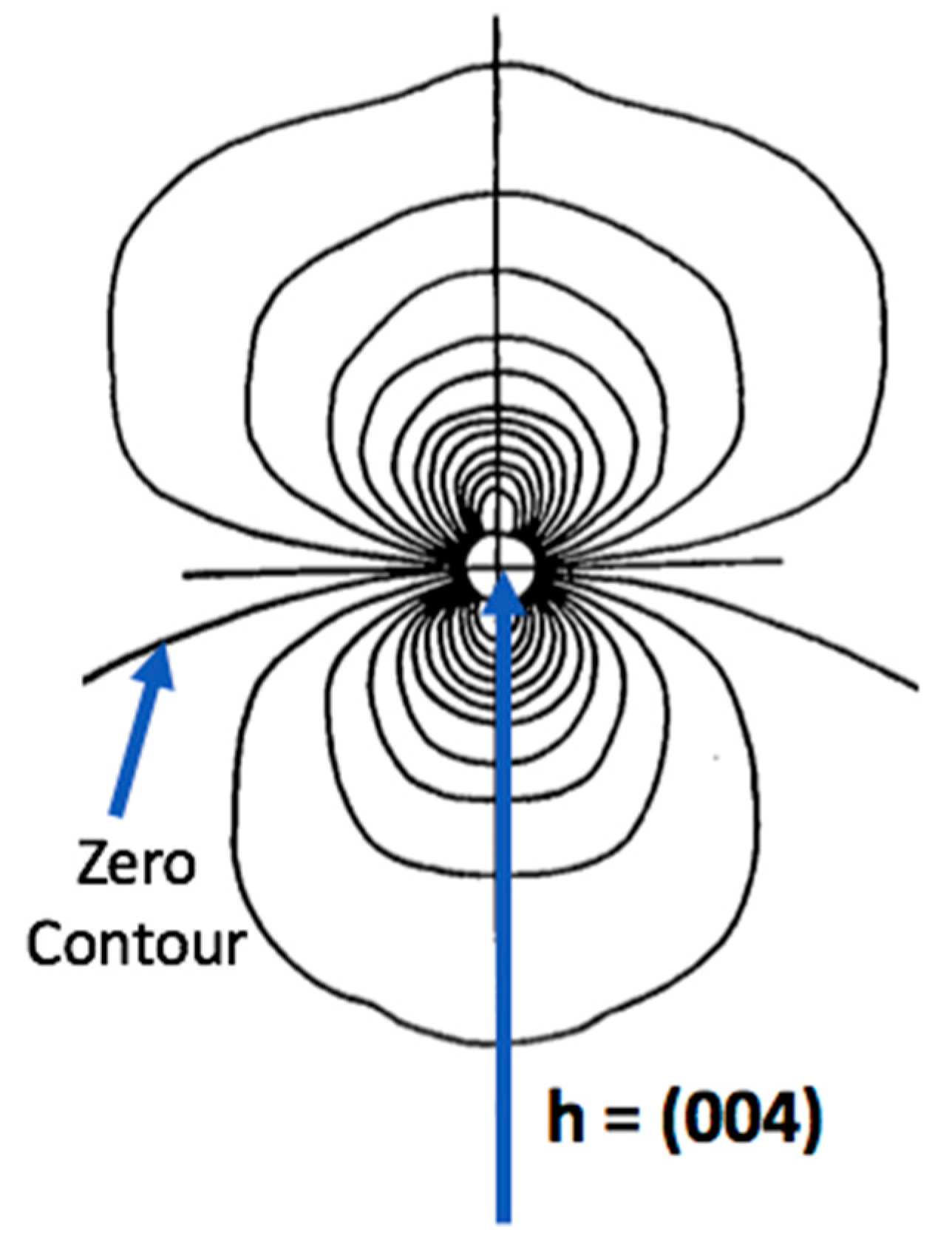
Historically, Ekstein [7] and Huang [2] were the first to address defect diffuse scattering in their investigations of the scattering from dilute impurity-induced lattice distortions in alloys. Ekstein derived in 1945 the characteristic q−2 wavevector dependence of the long-range distortion-induced diffuse scattering for small q, while Huang [2] in 1947 performed a more detailed investigation not only verifying the inverse q2 dependence, but also showing that the spherical symmetry of the displacements generated a plane of zero diffuse scattering intensity passing through the Bragg point and perpendicular to the reciprocal lattice vector. Of course, the work of Huang and Ekstein was performed at a time when neither high-resolution X-ray diffuse scattering measurements nor access to computer computational capabilities were available, and indeed it was not until 15–20 years later that high-resolution diffuse scattering measurements became available for accurate measurements on radiation-induced interstitials and vacancies. Nevertheless, as Cochran [8] and Cochran and Kartha [9,10], among others, revisited this area theoretically in the 1950s, and as the generality of the q−2 wavevector dependence for defect clusters was realized by Krivoglaz and coworkers [6,11], the q−2 scattering law for defect diffuse scattering was accorded the name Huang scattering.
Cochran [8] and Cochran and Kartha [9,10] revisited this issue using a somewhat different approach to that of Huang [2], but still based on the Fourier transform of a spherical crystal with a single defect embedded in the center. Cochran and Kartha, working at the Cavendish Laboratory in Cambridge University, had access to the so-called EDSAC early computer that was built in the Mathematical Laboratory at Cambridge, and so produced the detailed contour plot shown in Figure 1. This figure shows the characteristic lemniscate shape (Cochran and Kartha [10]) of the diffuse scattering from defects with spherical symmetry displacement fields (see Figure 1), illustrating the zero-intensity plane that passes through reciprocal lattice points and is normal to reciprocal lattice vectors as q goes to zero.
2.3. Diffuse Scattering Theory and Experiment Advances in the 1960s and 1970s
In the 1960s, Krivoglaz [5,6,11,12,13] and collaborators transitioned the theory of diffraction from crystals with defect clusters to a new level by transforming the analysis from a largely crystallography-based approach to that of a branch of theoretical physics via the implementation of a rigorous microscopic fluctuation theory formalism. Publishing at least 25 papers related to this area between 1958 and 1970, Krivoglaz and colleagues applied physical insight, as well as mathematical rigor, within microscopic fluctuation physics to the theory of diffraction from crystals containing point defect clusters. Unfortunately, as pointed out by Dederichs [3], even though largely published in Russian journals with English translation after the mid-1950s, these papers in the Russian literature did not receive the attention they deserved.
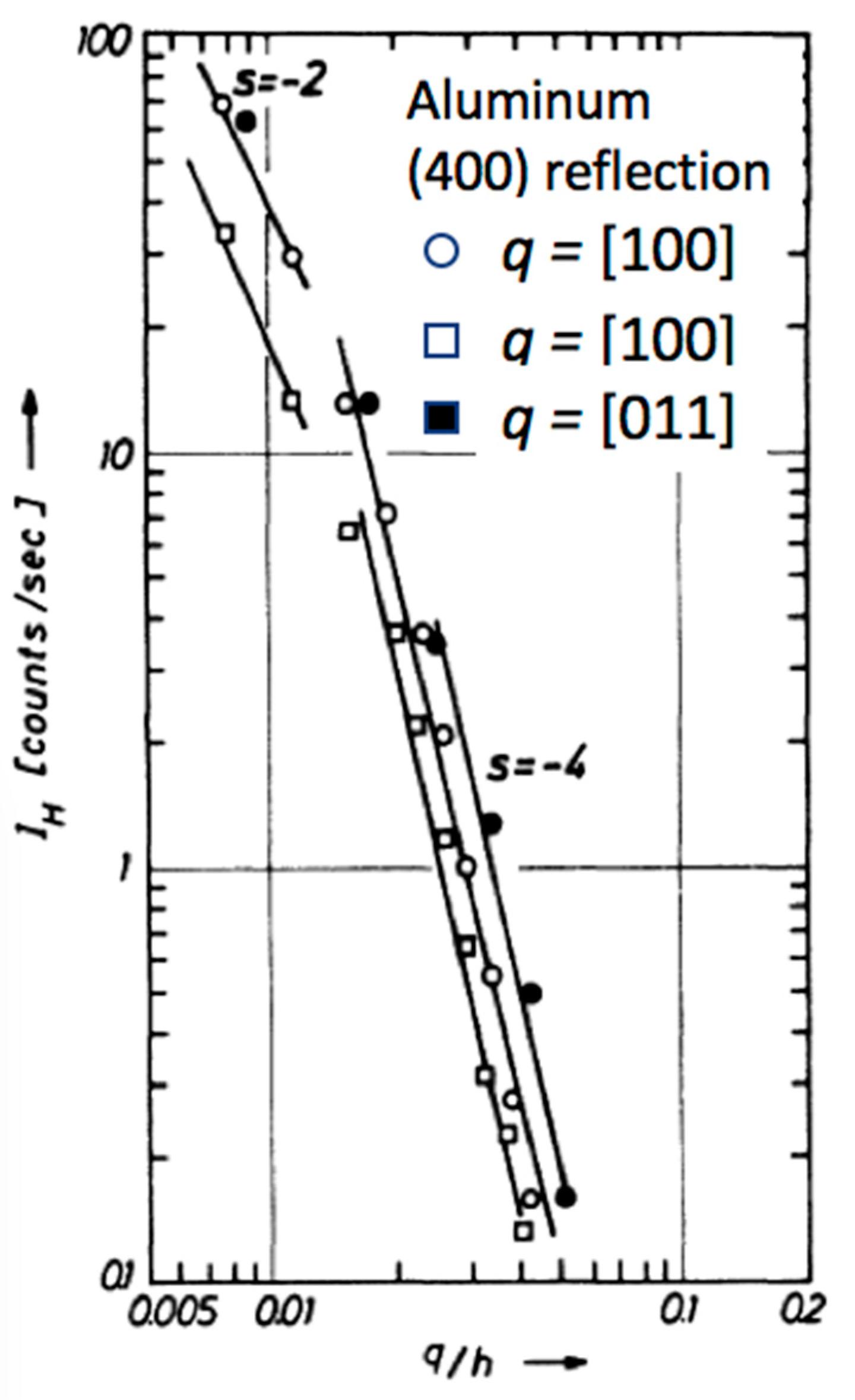
However, after translation of his book entitled X-Ray and Thermal Neutron Scattering by Real Crystals by Krivoglaz into English in 1969, the Krivoglaz approach to the theory and analysis of diffuse scattering from point defects and point defect clusters, such as small dislocation loops and precipitates in dilute alloys, became influential, especially in the theoretical development of the field. Although Krivoglaz’s methods focused almost exclusively on approximate closed-form solutions rather than numerical computations, his theoretical groundwork provided a basis for aggressive theoretical and experimental radiation-induced defect investigations initiated in the late 1960s and early 1970s. For instance, Dederichs [3,4], Trinkaus [14,15], and Eisenrigler [16] addressed the theoretical aspects of X-ray diffuse scattering from point defects and point defect clusters, while Ehrhart and Schilling [17] and Haubold [18] and their collaborators played leading roles experimentally in investigating the structure of interstitials in low-temperature electron-irradiated metals utilizing analyses based on the theoretical progress. Similarly, Peisl and collaborators [19,20] used X-ray diffuse scattering to investigate defect clusters in gamma-irradiated alkali halides, and also the structure of point defects and small clusters in displacement cascades produced during liquid-helium-temperature neutron irradiation of metals. These theoretical and experimental diffuse scattering investigations of the structure of single interstitials were successful in their aim; they determined unambiguously the crystallographic structure of interstitials in face-centered cubic metals to be <100> dumbbells. In the process of investigating the clustering of interstitials during warm-up from liquid helium temperature, they analyzed the diffuse scattering shape changes to determine the characteristic size of interstitial clusters by making use of the cutoff (qcuttoff) of the Huang scattering and the transition to a 1/q4 falloff to roughly identify the size of clusters to be R ~1/qcuttoff. This is illustrated in Figure 2, where, after annealing from the 10-K irradiation temperature to 138 K, the break in the 1/q2 dependence indicated the dislocation loops sizes to be 5–7 Å. Because the intensity of Huang scattering is proportional to the square of the defect misfit volume (i.e., for loops, and, for spherical defects, , where is the strain in the volume), the size estimate is weighted toward the largest sizes in the distribution, the fourth moment for loops and the sixth moment for spherical defect clusters.
While investigating diffuse scattering from point defects is not the focus of this paper, until the 1960s, the diffuse scattering formalism for the spherical symmetry displacements from atomic size mismatch in dilute and concentrated binary alloys proved to be formidable enough. Fortunately, as Krivoglaz pointed out in the preface to his books [6,13], with the use of powerful tools associated with microscopic fluctuation theory, it was possible to transition to the tools of theoretical physics rather than the previous more crystallography-based formalisms. The scope of this paper does not include the study or interpretation of straight dislocation distributions. Of importance in this connection, however, is the distinction between the diffraction from samples with long, straight dislocations compared to the scattering from small, tightly curved dislocation loops and small precipitates that was addressed by Krivoglaz.
Krivoglaz [11,12] quantified the pivotal distinction between what he termed type-1 defects that did not result in diffraction line broadening at the full-width at half-maximum (FWHM) and type-2 defects that generate line broadening at the FWHM. He pointed out that the convergence (or divergence) of the Debye–Waller factor for crystals with type-1 (or type-2) defects was the key factor. That is, he argued that the critical factor is the volume integral of the argument in the exponent (i.e., ) of the Bragg reflection Debye–Waller factor. Since the integral given by r diverges for a type-2 defect (e.g., long, straight dislocations with 1/r falloff of displacements), then the Debye–Waller factor goes to zero and there is no single delta-function Bragg reflection, but only overlapping distributions of relatively sharp diffuse scattering peaks reflecting a range of elastic strain distributions within the sample. On the other hand, if this integral remains finite as for a type-1 defect (e.g., small dislocation loops with 1/r2 falloff of displacements), the Bragg peak is diminished somewhat in intensity, but remains finite and retains its intrinsic width; actually, within dynamical diffraction theory, the Bragg peak width decreases for type-1 defects because the intrinsic linewidth for perfect crystals is proportional to the atomic scattering factor that is reduced in magnitude by the Debye–Waller factor. Krivoglaz pointed out specifically that, if the long-range displacement field falls off faster than 1/r3/2, the integral remains finite, such as for dislocation loops with a 1/r2 falloff, compared to the 1/r falloff for straight dislocation lines which falls off slower than 1/r3/2.
2.4. Diffraction Line Profiles for Crystals Containing Dislocation Loops
With the above discussion of the single-defect approximation and the recollection of historical developments and applications of diffuse scattering leading into the 1970s, consideration turns to the development and application of X-ray diffuse scattering to probe the type, size, and concentration of clustered defects in materials. It is to be understood that the defect clusters considered will have sizes small compared to the diffraction extinction length, i.e., the longest correlation length for a particular Bragg reflection, which means restricting clusters to a few hundred Angstroms in radius or less for low-order Bragg reflections. For dislocation loops approaching typical primary extinction lengths of a few micrometers, the X-rays will begin to probe the loops as separate dislocation lines, resulting in line broadening at the FWHM.
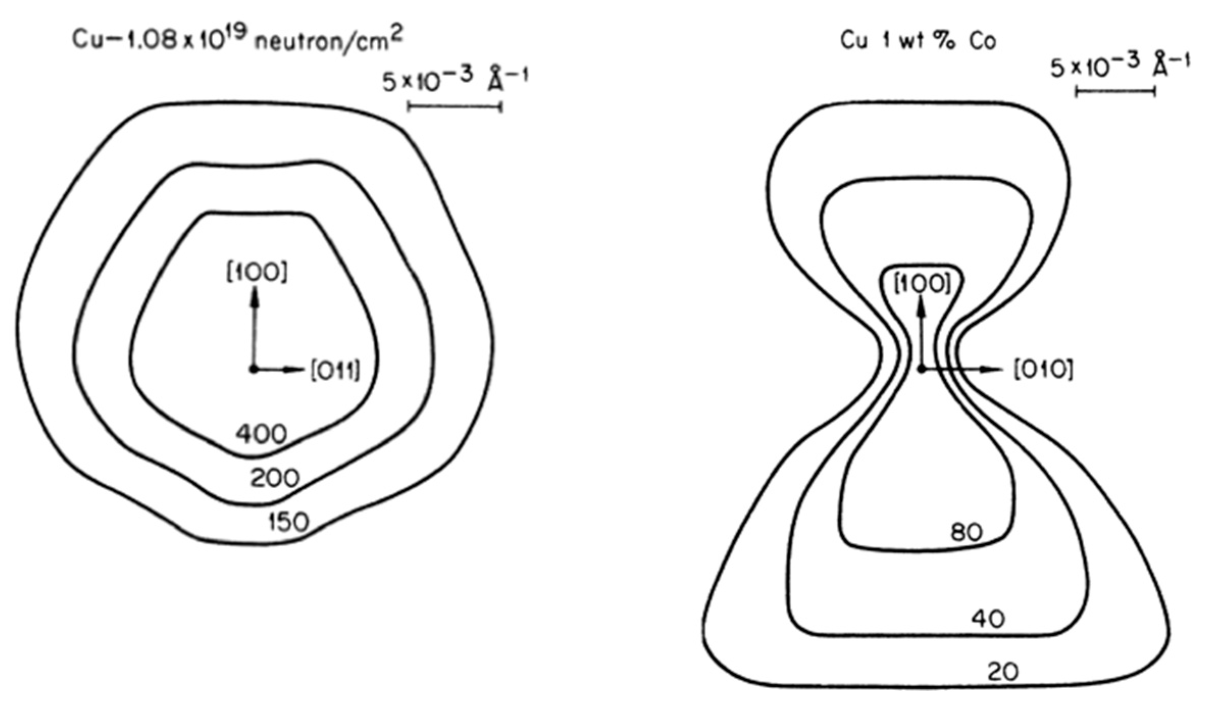
Analogous to the use of Huang diffuse scattering to determine the structure and symmetry of single interstitials introduced by liquid-helium-temperature electron irradiation, Larson and Schmatz [21] demonstrated the ability of Huang scattering to probe the symmetry of neutron irradiation-induced dislocation loops in copper and of spherical cobalt precipitates in aged Cu-1wt%Co. Because of the very small q-range of the Huang scattering for the up to 50–100-Å-radius dislocation loops and Co precipitates, a high-resolution triple-crystal diffractometer was used to make the measurements shown in Figure 3. Because the dislocation loops populate all {111} type planes in the neutron-irradiated sample, they produce diffuse intensity in all directions due to the anisotropic displacements directed largely normal to all <111> directions. On the other hand, for the spherical Co precipitates, there is a minimum in the Huang scattering perpendicular to the (200) reciprocal lattice vector, which indicates the spherical symmetry of the displacement field surrounding cobalt precipitates. X-ray scattering investigations of precipitates is addressed in detail in Section 2.5 below.
The characteristic 1/q2 dependence of the Huang scattering dominates the diffraction line profile at small q and, as discussed in connection with Figure 2 above, the magnitude of the intensity in the Huang region is proportional to the fourth moment of the size distribution for planar dislocation loops and the sixth moment for three-dimensional spherical precipitates. Moreover, because the Huang scattering probes the symmetry of the long-range displacement fields of the defects, it does not contain direct size information on the defect clusters. The magnitude of q corresponding to the transition from the 1/q2 to the ~1/q4 falloff does, however, provide a rough (albeit a high moment) approximation of the cluster size in that the transition q corresponds roughly to the inverse of the distance at which () in the exponential in Equation (6) becomes ⪆1. There is of course no information available on the distribution of sizes from the extrapolated intersection point of the q−2 and q−4 slope lines. Rather, as is discussed below, information on the distribution of sizes is contained in the detailed shape of the transition, and also the detailed shape of the diffuse scattering for large q. Therefore, for accurate determinations of defect cluster size distributions by fitting diffuse scattering measurements out to large q, accurate diffuse scattering cross-section calculations are needed as a function of size for the loops or precipitates.
Fortunately, the single-defect approximation form of the scattering expressed in Equation (6) lends itself to a straightforward method for accurate numerical calculations of the scattering cross-sections and, hence, to accurate diffuse scattering intensities defining diffraction line profiles. Moreover, the displacement fields u(r) in Equation (6) plus the structure factor of the defect clusters, e.g., dislocation loop atoms or precipitate atoms, provide the required information. Calculations of the cross-sections in numerical form as a function of defect type, size, and orientation made it possible to extract detailed information on defect cluster size distributions directly from experimental measurements by fitting the calculated cross-sections to radial diffuse scattering measurements in single crystals (such as in Figure 2). Larson and Schmatz [22] performed such calculations for dislocation loops in aluminum using displacement fields calculated numerically for prismatic dislocation loops on {111} planes by Ohr [23]. For reference, Gao and Larson [24] discussed displacement fields for non-circular and circular dislocation loops, providing two-dimensional (2D) color contour plots of the elastic strain fields associated with the displacements.
Keating and Goland [25] in 1974 performed displacement field and diffuse scattering calculations for basal plane loops in graphite, predicting the form of dislocation loop scattering both close to and between reciprocal lattice points. Although the predictions of diffuse scattering for loops in graphite were compared with precession camera wet-film diffuse scattering measurements on neutron-irradiated natural graphite crystals, the agreement was only moderate, and no attempt was made to extract size distributions from the measurements. However, in 1982, Ehrhart et al. [26] provided a detailed description of numerically calculated diffuse scattering from circular dislocation loops, both with and without stacking faults in an isotropic face-centered cubic (FCC) crystal. The paper of Ehrhart et al. provided a perspective in terms of the inadequacy of existing analytical approximations for scattering from defect clusters and underscored the necessity of performing numerical calculations rather than analytical approximations to obtain results sufficiently accurate for analyzing experimental measurements in terms of dislocation loop size distributions. Because the focus in Ehrhart’s paper was on providing an understanding of the overall range of diffuse scattering effects associated with dislocation loops and planar stacking faults, direct comparisons between theory and experimental measurements were outside the scope of that work.
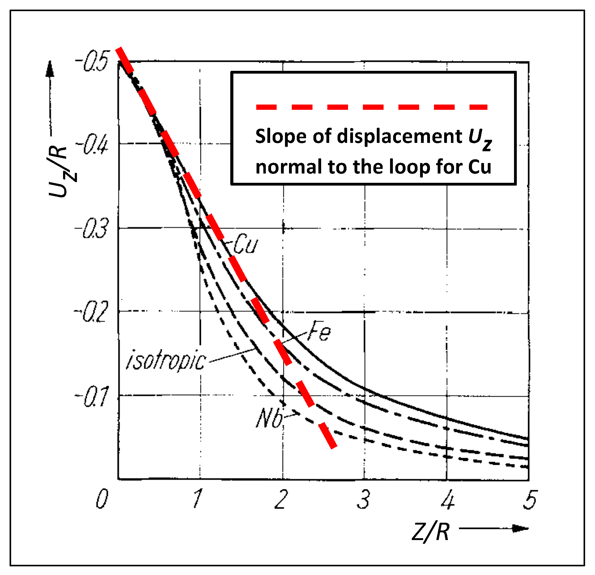
Subsequent to the calculations for dislocation loops in aluminum [22] and the insight provided by the results contained in Figure 5 of Reference [26], Larson and Young [27] investigated the diffuse scattering implications of the form of the displacement field for loops as a function of r within the close proximity of the loop plane. As can be seen in the loop displacement fields plotted in Figure 4, which represents the work of Ohr [23], there is an inflection point in the loop-normal displacement field for loops. This occurs as the loop-induced displacements transition from the convex 1/r2 dependence at long range to a concave dependence as the displacements reach their ultimate limit of b/2 at the loop plane, Z = 0. Accordingly, as illustrated by the thick (red) dashed line superposed on the displacement field calculations of Ohr, there is an extended region within which the loop-normal displacements decrease linearly with increasing r. Then, since the loop-normal elastic strain is given by the gradient of the loop-normal displacements, , the loop-normal strain is essentially constant within a distance ~R of the loop and, for Cu, was found to be over a spherical volume with a radius ~R centered on the loop.
The significance of this result in terms of the ability to extract loop sizes and size distributions from diffuse scattering cannot be overstated because it provides an accurate method to extract size distributions for dislocation loops directly from diffuse scattering measurements. That is, since for small q in the radial direction, the lattice strain is related to the ratio of q to the reciprocal lattice vector h through , the diffuse scattering from the immediate vicinity of the loop arises from a three-dimensional (3D) volume of radius , which can be identified as “local Bragg scattering” at , in the so-called “Stokes–Wilson” or “asymptotic” scattering region. Although the asymptotic scattering region is too complicated to be handled analytically in closed form [14], numerical calculations of the scattering from loops can be performed straightforwardly for vacancy (b < 0) and interstitial (b > 0) loops of desired sizes on specified lattice planes using Equation (6) and the displacement field calculations of Ohr [23]. Accordingly, Larson and Young demonstrated, in conference proceedings [27] in 1982 and in a more complete journal paper [28] in 1987, the ability to extract separate size distributions for vacancy and interstitial loops from diffuse scattering measurements. Size distributions were extracted directly by non-linear least-squares fitting of cross-sections for 10–60-Å-radius vacancy and interstitial {111} loops to X-ray diffuse scattering measurements on neutron-irradiated Cu in Reference [27] and on both Ni-ion-irradiated and neutron-irradiated Cu in Reference [28].
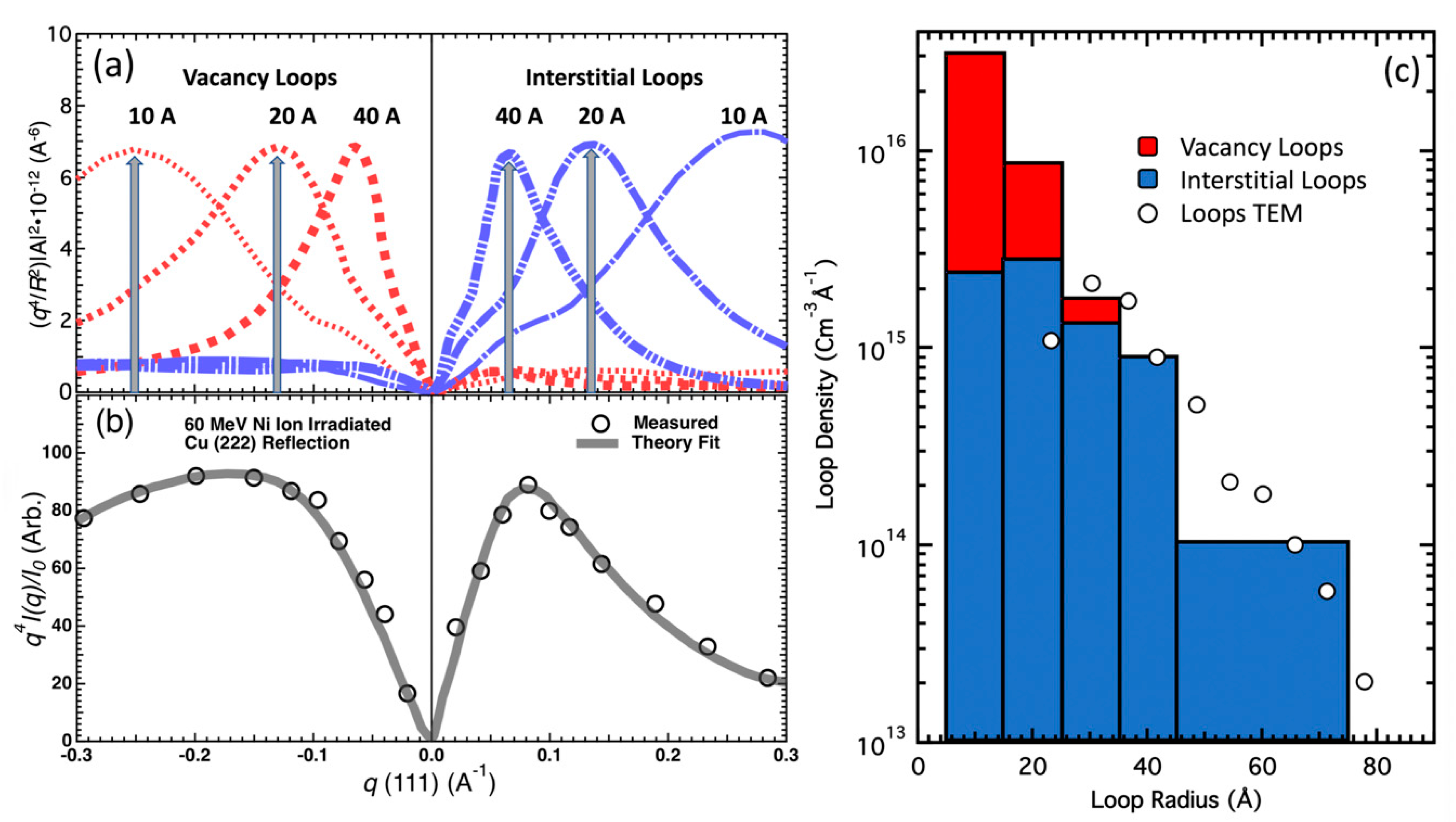
As an illustrative demonstration of the diffraction line-profile analysis of X-ray diffuse scattering to probe vacancy and interstitial loops in irradiated materials, the results in References [28,29] are considered in some detail. Firstly, to reveal the details of diffuse scattering in the asymptotic region (i.e., ~q−4 intensity falloff), it is useful to scale the scattering cross-sections and the diffuse scattering measurements by q4, where q is the radial distance (parallel or anti-parallel) to the reciprocal lattice vector as shown in Figure 5 below. Figure 5 is a composite describing the extraction of vacancy and interstitial loop size distributions from X-ray diffuse scattering measurements as discussed in References [27,28,29]. The measurements were performed near the (222) Bragg reflection on a copper single crystal that was irradiated with high-energy 60-MeV Ni-ions for a previous “integral” diffuse scattering study [30]. Note that “integral” diffuse scattering is a rocking-curve (not a radial line-profile) experimental measurement with a simplified/approximate dislocation loop scattering model [31,32] that does not separate the scattering from vacancy and interstitial type loops. Scaling by q4 not only emphasizes the details of the asymptotic region, but it also renders the Huang scattering close to the Bragg reflection a quadratic function of q that vanishes as q goes to zero at the Bragg peak. It should be cautioned that the q4 scaling of diffuse scattering requires statistically precise measurements at large q, especially considering that the thermal diffuse scattering must be removed before the analysis.
As indicated in panel (a) of Figure 5, the scattering cross-sections as a function of R were scaled by q4/R2 rather than just q4; for planar loops, this scaling is proportional to the cross-section per point defect in loops of radius R. As such, the relatively constant peak heights as a function of R underscore the fact that the intensity in the asymptotic scattering region is known [4,14,15] to provide a probe of the number of point defects (vacancies or interstitials) given for planar loops by , where is the atomic volume. As mentioned above, the q-positions of the peaks of the numerically calculated cross-sections scale inversely as R according to ; the widths of the scattering peaks also scale inversely with R due to size effect broadening. These aspects associated with “local” Bragg scattering provide a robust and intuitive foundation for the extraction of separate size distributions for vacancy and interstitial loops from diffuse scattering measurements. For instance, by comparing the positions and shapes of the peaks of the measured diffuse scattering in Figure 5b with the positions of the vertical gray arrows in Figure 5a, it can be seen semi-quantitatively that interstitial loops with radii between 20 and 40 Å contain the highest number of interstitials, and that vacancies tend to be stored preferentially in smaller loops with radii ~10–20 Å.
Whereas the shapes of the scaled diffuse scattering intensity in Figure 5b provide information on the distribution of point defects in loops (i.e., second moment of size distributions), the vacancy and interstitial loop size distributions are shown in Figure 5c, as obtained by fitting the measured diffuse scattering data with cross-sections for 10-, 20-, 30-, 40-, and 60-Å-radius vacancy and interstitial loops averaged over the four {111} planes. The thick gray lines in Figure 5b represent the fits to the measured scattering with no adjustable scaling factors; thus, the densities of loops for each size represent absolute densities as plotted in Figure 5c. Because the vacancy and interstitial loop size distributions overlap, the vacancy loop densities are plotted in red on top of the blue densities for interstitial loops. It is noted that the combined size distributions form an exponentially decreasing density of loops with size, as is generally observed for room-temperature ion and neutron radiations. However, the vacancy component is confined to 30 Å or less, while the interstitial component extends to at least 60 Å.
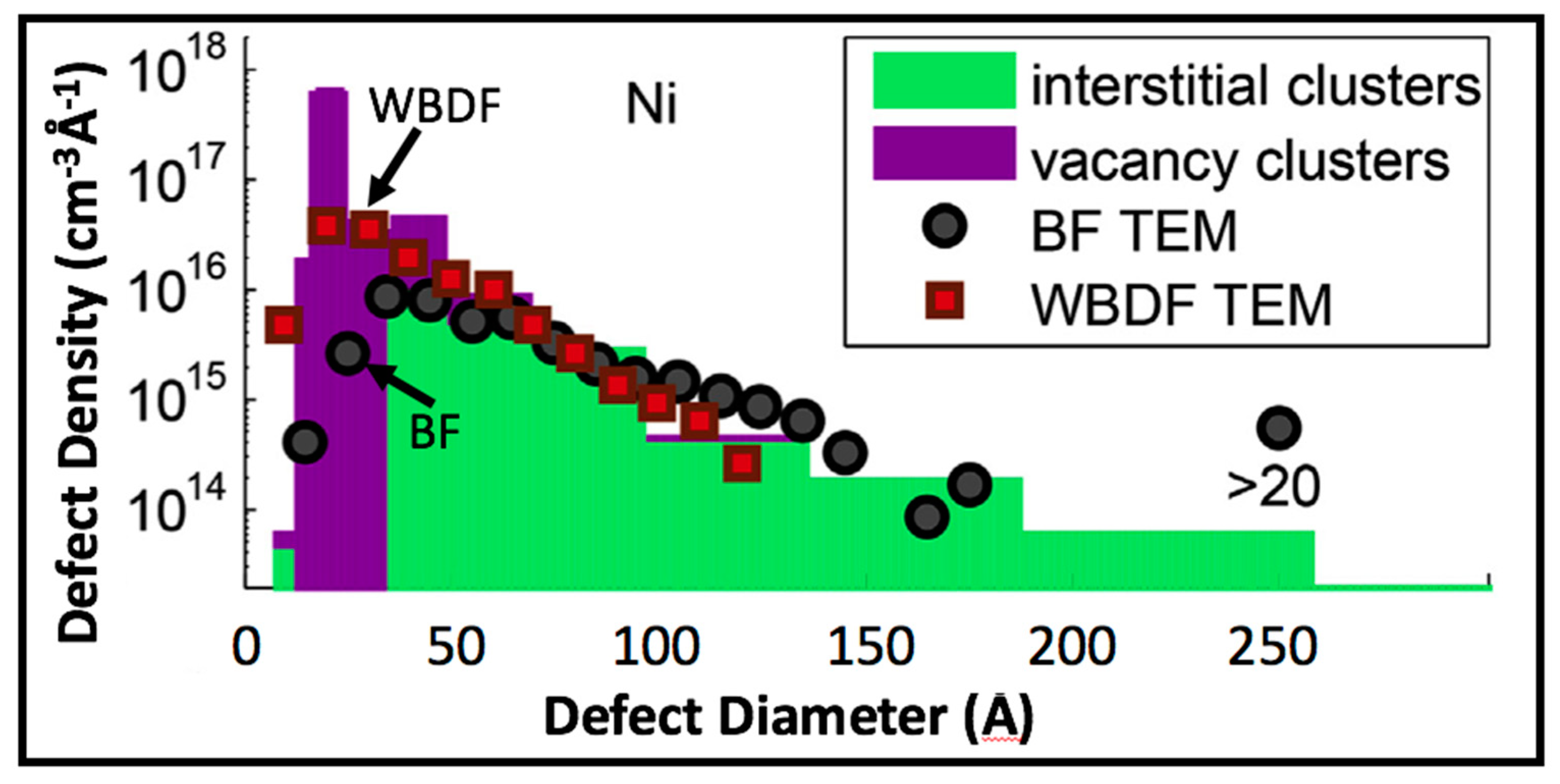
It is important to note, in regard to the TEM measurements of the combined dislocation loop densities, that the X-ray and TEM cluster densities are in good agreement down to R ~30 Å, but that the TEM densities are much lower than the X-ray densities for 10- and 20-Å loop radii. The good agreement for the larger sizes (that are easier to image by TEM) indicates that the X-ray diffuse scattering analysis discussed here provides accurate and absolute defect densities and sizes. Disagreement between X-ray and TEM size distribution determinations were observed in the small-size ranges in a number of cases [30,31,33] and attributed in each case to limitations in the resolution of TEM imaging. As illustrated in a more recent comparison [34] between X-ray and electron microscopy size distributions in Figure 6, electron microscopy resolution today is capable of imaging loops significantly smaller than 20-Å radii when weak-beam dark-field (WBDF) imaging is used, and of course much smaller sizes using high-resolution lattice imaging. However, as indicated in the Figure 6 comparison between WBDF and bright-field (BF) defect cluster densities in ion-irradiated Ni, bright-field densities start to fall below WBDF at ~20-Å radius, and, by ~10-Å radius, BF densities are a factor of ten less than WBDF densities. Since most vacancy loops are in the smaller-size range under these irradiation conditions, the resolution effects impact vacancy loop densities and sizes more strongly than for the interstitial loops.
Ehrhart and Averback [33] in 1989 used the above X-ray diffuse scattering analysis technique to perform an extensive investigation of dislocation loop production and evolution in 6-K electron-irradiated and neutron-irradiated pure Ni and Cu, and in very dilute alloys (NiSi0.01, NiGe0.01, and CuBe0.001) to probe the impact of impurity trapping of defect clusters in irradiated materials. In their study, asymptotic diffuse scattering measurements were made on each of the samples after annealing to room temperature (295 K) and also after annealing to nominal temperatures of 470 K and 700 K. They assessed their measurement results qualitatively in terms of the q-dependence of q4-weighted intensity plots as informed by diffuse scattering plots as a function of R analogous to those in Figure 5a above. They also analyzed the measurements quantitatively by extracting vacancy and interstitial loop size distributions analogous to Figure 5c as a function of the various annealing temperatures, in order to determine the impact of electron irradiation versus neutron irradiation on the production and evolution of vacancy loops in pure Ni after annealing to 295 K, below the so-called stage-III temperature at which single vacancies become mobile. With respect to Ni and Ni alloys, both the qualitative analysis of the q4-scaled diffuse scattering curves and the quantitative fitting of the diffuse scattering demonstrated that vacancy clusters are formed spontaneously during the rapid cooling phase of displacement cascades in low-temperature neutron irradiation, and that vacancy clusters are not formed until stage-III annealing in the electron-irradiated case. They further showed that Si dopant atoms in Ni strongly suppress the sizes of dislocation loops after both electron and neutron irradiation, providing insight into high-temperature irradiation behavior of alloys.
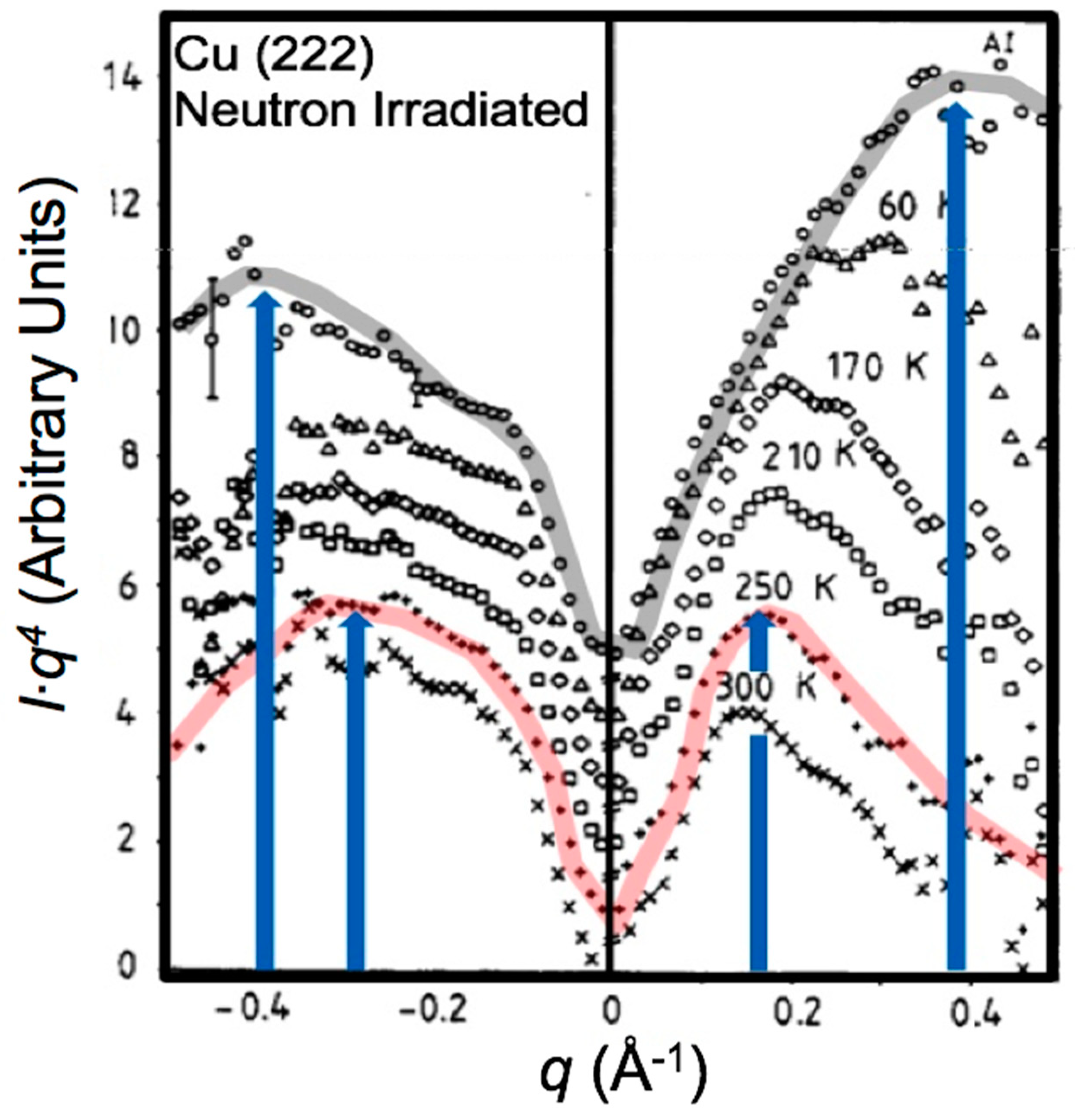
Rauch et al. [35] performed a detailed annealing study between 10 and 300 K of the generation and evolution of defect clusters produced by fast neutron irradiation at 4.6 K in Cu, which is complementary to the low-temperature neutron irradiation (AI) results for Cu in Reference [33], in that it provides an important as-irradiated (10 K) measurement, as well as a more dense set of annealing temperatures up to 300 K. Figure 7 shows q4-scaled asymptotic scattering measurements performed in Reference [35] after irradiation (AI; 10 K) and after annealing to temperatures of 60, 170, 210, 250, and 300 K. Note that the zeros (i.e., where q4 = 0) on the intensity scale for the different temperature anneals were offset in the graph to avoid overlap of the intensities and shapes on the negative-q (vacancy) side for anneals above 60 K; the vacancy cluster diffuse scattering can be seen to be nearly unchanged in shape and intensity with annealing temperatures above 60 K. The shapes and the intensities of the AI measurements performed at 10 K and their respective changes upon annealing to 60 K are important. Firstly, as the intensities at the q-positions of the outer blue arrows indicate, there are clearly large numbers of small interstitial clusters and vacancy clusters of comparable size. Although the AI measurements were not analyzed in terms of densities and size distributions directly, the AI measurements in principle quantify the size and density of vacancy and interstitial clusters that are generated directly within displacement cascades.
The spontaneous formation of small vacancy and interstitial clusters during cascades is a result that was predicted in recent years by molecular dynamics cascade simulations for Cu [36,37]. Moreover, the large decreases in scattering intensity observed near the outer arrows after the 60-K anneal indicate the fragile stability and mutual annihilation of small metastable clusters. This is especially true of the vacancy component, whereby the loss of intensity from ~0.3–0.5 Å−1 in q results in diffuse scattering (and, hence, size distributions and cluster densities) that remain essentially constant in intensity and shape during thermal anneals from 60 K all the way up to 300 K. This visually observable lack of change in the vacancy loop diffuse scattering in Figure 7 is also reflected quantitively in the analysis reported in Reference [35] in the form of nearly constant vacancy loop densities and size distributions. Similarly, the shift of the interstitial loop scattering maxima to lower q (indicated by the inner blue arrow) and the decreasing peak intensity with increasing annealing temperature is reflected in the size distribution analysis in Reference [35] as the loss of small interstitial loops concomitant with increases in the number of large loops. This is as would be expected for loop glide and aggregation and not for interstitial loop shrinkage, since interstitials would require energies of ~5 eV or a temperature of ~700 K to be emitted from loops.
In more recent X-ray diffraction line-profile investigations, Olsen et al. [34] compared dislocation loop damage in Ni and NiCo produced by Ni-ion irradiation in terms of vacancy and interstitial loop size distributions, and the distribution of point defects in clusters as a function of loop sizes. This work was part of a study directed toward understanding the impact of alloying in Ni-based concentrated solid solutions. In addition, Sun et al. [38] studied vacancy and interstitial dislocation loop production as a function of dose in Cu-ion-irradiated tungsten. Both low-energy ion irradiation and high-energy ion irradiation behavior are of interest in connection with fusion energy reactor first wall damage.
The development and application of diffuse scattering profile analyses for crystals containing distributions of vacancy and interstitial loops is dwelt upon in detail here because defect diffuse scattering from clusters received the largest amount of attention theoretically and experimentally. As discussed above, this was true especially in the late 1960s and early 1970s as detailed fundamental investigations of radiation damage in metals were undertaken at universities and national laboratories across the world to understand the underlying science of defect cluster production and to predict irradiation damage accumulation and evolution in nuclear reactors. Moreover, the powerful TEM techniques that exist today and, in particular, the imaging resolution for small-defect clusters were relatively early in their development.
2.5. Diffraction Line Profiles for Crystals Containing Coherent Precipitates
X-ray diffraction observations of coherent precipitates date back to the identification of so-called Guinier–Preston zones in 1938 [39]. Guinier–Preston zones play a remarkable role in metal alloy technology and a vast literature exists. Although there is really no scientific distinction between Guinier–Preston zone X-ray scattering and diffraction line-profile analysis of materials with coherent precipitates, the overall field of Guinier–Preston zone research is very broad and is well documented in its own right. Because of the limited scope of the present paper, the discussion regarding precipitates here focuses on understanding the diffraction formalism and discussing the underlying science of line-profile analysis by concentrating on a single dilute alloy Cu-1wt%Co as an illustrative example of line-profile analysis for crystals containing coherent precipitates.
Diffraction line profiles for crystals containing coherent second-phase spherical precipitates were addressed by Krivoglaz [11] in 1960 for several cases: one in which the precipitate atoms have a constant density up to the outer edge of the precipitate, and for two cases in which a layer with diminished precipitate atom density forms at the outer edge of the precipitate. These closed-form approximations of Krivoglaz are quite complex and do not seem to have been tested for applicability. However, formulations based partly on these and other early concepts of Krivoglaz were published by Dederichs [3,4] and Trinkaus [15] in the early 1970s using double-force tensors to explore the symmetry of the long-range displacement fields for both clustered and single-atom defects in crystals. In addition, Trinkaus studied the asymptotic (large q) form of diffuse scattering for precipitates within the infinitesimal distortion center approximation [14] using a local Bragg scattering concept dating back to the work of Stokes and Wilson [1] and analyzed by the method of steepest descent.
As noted with reference to Figure 3 above, the analytical work of Dederichs and Trinkaus provided excellent theoretical guidance for extracting the local symmetry of defects using first-order expansion of Equation (6) in terms of the Huang scattering. As discussed in connection with Figure 3 above, this was true for single interstitials and for both irradiation-induced dislocation loops and coherent Co precipitates in Cu through measurements of the symmetry of Huang diffuse scattering near Bragg reflections. However, just as for the case of dislocation loops discussed in the previous section, the extraction of size distributions and densities for precipitates from diffuse scattering measurements requires numerical calculations of the large q cross-sections in Equation (7).
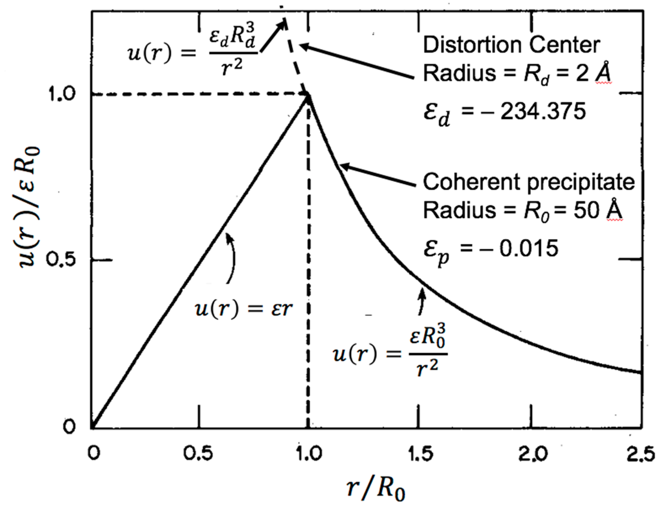
As illustrated in Figure 8, for elastic isotropy, the lattice displacements for spherical precipitates are particularly simple in that they are radially symmetric. Moreover, the displacements can be written in two parts as inside the precipitate and outside the precipitate, where the displacements are equal at the precipitate radius , and is the strain relative to the host lattice. Although displacement fields for spherical precipitates are very different from dislocation loops in character overall, it is useful to compare the lattice displacements normal to a dislocation loop in Figure 4 (above) with the radial displacements for a coherent precipitate with strain in Figure 8. There is commonality in that each has a region of constant strain at/within the defect cluster and both have an inverse-square falloff for large r. However, they differ qualitatively in that oversized precipitate atoms generate a positive (expansive) misfit dilatation inside the precipitate and a negative (compressive) dilatation outside the precipitate if , and vice versa for . For interstitial loops, the dilatation is negative (compressive) for all r normal to the loop, and there is a positive (tensile) dilatation for all r normal to vacancy loops. Just as the linear displacement falloff for dislocation loops generates local Bragg scattering, the linear displacements within the precipitate produce local Bragg scattering from the precipitate. It is shown below that this local Bragg scattering produces a signature of the lattice parameter within the precipitate by its position, q, relative to the host crystal Bragg peak.
For coherent precipitates, the diffuse scattering amplitude can be written [29,40] in a form analogous to Equation (6) as
where is the precipitate scattering factor, is the host scattering factor, is the precipitate radius, and represents precipitate atom displacements. The first sum is over the precipitate atoms that vanishes if , and the second sum is over all atoms. For simplicity, here, the Huang scattering term corresponding to the first-order term in the expansion of is not separated out to be calculated analytically. As discussed in References [29,40] it is convenient for high-accuracy diffuse scattering cross-sections at small q to write the second term in Equation (7) as
because K as the Fourier transform of K can be calculated in closed form for anisotropic cubic crystals [4,15,22], while converges very slowly because it oscillates for large r in the summation. For reference, K represents the Huang scattering amplitude.
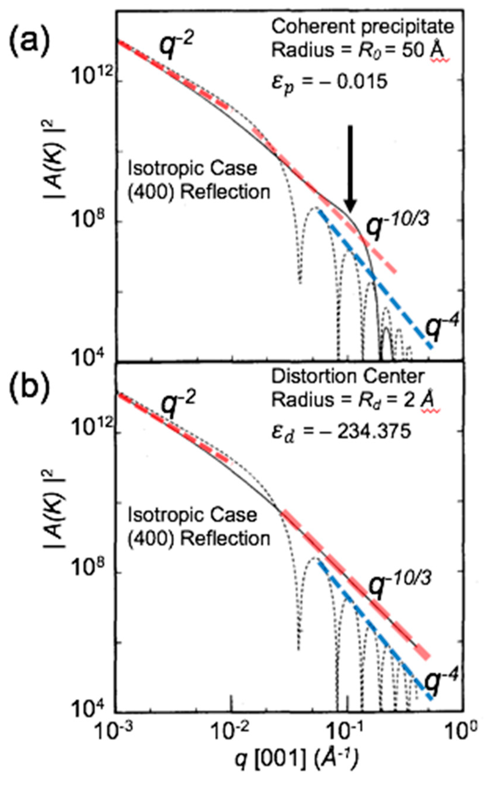
Although the asymptotic diffuse scattering for finite size spherical inclusions is tedious to handle analytically [4,14], for the case of elastic isotropy, the lattice sums can be reduced to a one-dimension numerical integral. This fact was exploited by Iida and Larson [29,40] to test the analytic approximations [14] for distortion centers of vanishing size (i.e., infinitesimal defect approximation) and to analyze diffuse scattering profile measurements for Co precipitates in Cu-1wt%Co. As shown in Reference [40] and Figure 8 here, the radial displacement curves for a finite-radius (R0) spherical precipitate in an elastically isotropic material has a relatively simple form with linearly increasing displacements inside the precipitate and quadratically decreasing displacements outside the precipitate. The dashed upward curving line in Figure 8 illustrates (in connection with the lower panel in Figure 9) further that it is possible to approximate the analytical case of a vanishing radius distortion center by calculations for a very-small-radius ( = 2 Å in this case) precipitate with an (unphysical) strain . This strain was chosen such that the displacement at r = 50 Å for an = 50 Å coherent precipitate with a strain would be equal to that of the = 2 Å precipitate, both of which have the same 1/r2 falloff rate from that point.
Figure 9 shows calculations [40] of the diffuse scattering for a vanishing size (2 Å radius) distortion center and the 50-Å-radius finite size precipitate. The thick dashed red lines in Figure 9a,b denote the q−2 and q−10/3 falloffs of the intensities expected for the Huang region at small q, and the analytically predicted q−10/3 falloff for a vanishing size distortion center at large q, and the dashed blue lines denote the rapidly oscillating q−4 falloff characteristic of diffuse scattering from regions close to defect clusters, where the r−2 dependence of the displacement u(r) leads to strong intensity oscillations as is reached. The results in Figure 9b verify the results of the analytical approximations of a q−10/3 falloff for the strong distortion center case with vanishing size. However, the plots in Figure 9a show that, for the case of a 50-Å-radius precipitate, the q−10/3 falloff is modulated by the appearance of a peak or shoulder structure at q ~0.1 Å, which corresponds to “local Bragg scattering” from the constant lattice strain within the precipitate. Moreover, at larger q (i.e., beyond the local Bragg peak position), the diffuse scattering falls much more rapidly than q−10/3 due to the truncation (at the precipitate radius) of the r−2 form of the displacements, which is responsible for the q−10/3 form that persists for the infinitesimal distortion center in Figure 9b. As shown in References [38,39] and discussed in Reference [29], scaling the diffuse scattering in Figure 9a by provides the basis for a linear (i.e., not log) plot for large q for spherical precipitates, which is analogous to the plots for individual dislocation loops in Figure 5a above. The peak/shoulder position indicated by the black arrow in Figure 9a turns into a peak at q = 0.1 Å−1 in the -scaled plot [38]. The q-position relative to the Bragg peak provides only an approximate measure of the precipitate strain because more than one scattering amplitude contributes to the diffuse scattering; the width of the peak provides an inverse measure of the size. Just as for dislocation loops in Figure 5, the actual strain and size parameters are to be obtained by fitting the numerically calculated cross-sections for a range of sizes and strains to the q4-scaled plots of the experimentally measured diffuse scattering [29].
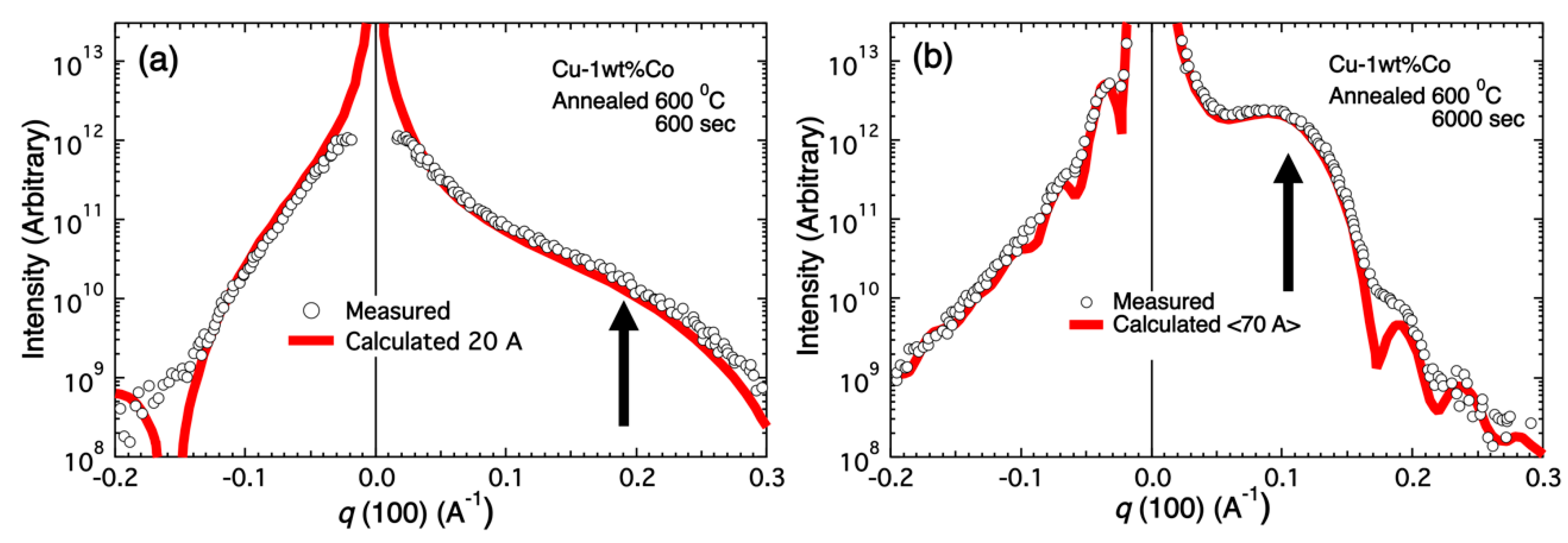
However, for the case of Cu-1wt%Co, because Cu is strongly anisotropic elastically, it is important to recognize that the separation in Equation (8) of the analytically calculated iK is necessary for accuracy, and that anisotropic displacement fields can be obtained by reverse Fourier transformation of for use in the lattice sum of Equation (8) [41,42,43]. As described in References [29,41], Figure 10 shows fits for samples with two sizes of Co precipitates. As described in References [29,39], Figure 10 shows measurements performed near the (400) Bragg reflection on Cu-1wt%Co single crystals that were aged at 873 K for 600 s and 6000 s following a high-temperature pre-anneal to dissolve the Co into solution. The thick red lines represent diffuse scattering calculations using parameters corresponding to strain for 20-Å-radius precipitates in the 600-s case and a volume-weighted average of scattering for precipitates with a distribution of sizes of 65-, 70-, and 75-Å radius for the 6000-s anneal. Excellent agreement is noted between the measurements and the diffuse scattering calculations, where the size of the Co precipitates in the aged Cu-1wt%Cocrystals are shown to have ripened to radii of 20 Å in 600 s and to average radii of 70 Å in 6000 s. The vertical arrows in Figure 10 indicate the position of the local Bragg scattering peak in q4-scaled plots (see References [29,40,41]) of the diffuse scattering intensities in Figure 10. Therefore, the measurement and analysis of diffraction line profiles for materials with coherent precipitates is well established and proceeds analogous to that for dislocation loops discussed in the previous section.
2.6. Atomic-Scale Simulation of Defect Cluster Displacement Fields
In the above sections, the diffuse scattering amplitudes for dislocation loops and coherent precipitates were obtained using continuum-elasticity-based lattice displacement fields. Furthermore, with the availability of accurate anisotropic displacement fields, it can be expected that continuum, hybrid continuum/lattice, and direct performance of lattice sums within the diffuse scattering amplitudes as calculated using Equation (6) or Equations (7) and (8) will be quite accurate. In the early 1970s, the computational power required for routine use of fully atomistic lattice sums with millions of atoms or more was not feasible. However, by the turn of the century in 2000, the routinely available computational power increased to the extent that Schaublin et al. [44,45] and Nordlund et al. [46] pointed out the possibility and potential advantages of using direct molecular dynamics (MD) simulations of displacement fields rather than continuum-elasticity models to determine the lattice displacements for two- and three-dimensional clustered defects with arbitrary configurations.
Later, MD simulations were used extensively to model structures of small vacancy and interstitial atom clusters such as perfect and Frank loops, and perfect and incomplete or irregular stacking fault tetrahedra-like vacancy clusters that are now often observed in MD simulations of displacement cascades [36,37,47,48,49] for neutron- or ion-irradiated metals. There are also studies comparing atomistic simulations with continuum displacement fields for dislocation loop structures [50,51]. However, it was demonstrated that atomic displacements for small clusters of both vacancy and interstitial nature are very difficult to reproduce by continuum-elasticity approaches, underscoring the importance of atomistic modeling as a useful step forward. For instance, large numbers of such small and meta-stable vacancy clusters represent the most likely candidates for the vacancy-type defect clusters that were annihilated during thermal anneal from 10 K to 60 K of low-temperature neutron irradiation-induced defects in Cu in Figure 8 above [35].
Of course, for MD, accurate atomic potentials are needed for the materials of interest. However, Nordlund et al. [46] showed that by (1) inserting defect clusters into the middle of lattice MD cells, (2) annealing the cell at an elevated temperature sufficiently long for the entire cell to relax, and (3) quenching to zero temperature, the displacement field surrounding the cluster is retained within the cell, and without random thermal displacements. The absence of thermal displacements is critical because (except for sub-picosecond pulse free-electron laser X-ray sources) experimental diffraction measurements probe the time-average atomic positions. As a result, lattice sums can be used for calculating the diffuse scattering amplitude for arbitrary defect cluster configurations without further input.
Diffuse scattering calculations using displacement fields generated by MD simulations for vacancy loops in Ni were compared by Olsen et al. [34] with calculations using continuum-elasticity displacement fields. It was found that, for vacancy loops with 45 vacancies (R, the diffuse scattering results for MD-determined lattice distortions have essentially the same result as diffuse scattering calculations performed using continuum-elasticity displacement fields (e.g., Ohr [23]). Although comparisons for smaller sizes of say 3–4-Å-radius vacancy loops were not discussed in the Olsen paper, such comparisons would be of interest because so-called edge effects for small vacancy loops are likely to lead to less than complete lattice collapse, whereas full collapse occurs when continuum displacement simulations are superposed on atomistic diffuse scattering calculation volumes. Therefore, to the extent that the MD potentials are accurate and tested for defects and elastic property applications, MD simulations have the potential to improve the accuracy of diffuse scattering for dislocation loops with radii below ~5 Å [48].
The situation for three-dimensional clusters like stacking fault tetrahedra or tetrahedral fragments represents a more compelling case for the use of MD rather than continuum elasticity for defect cluster displacement fields for defect clusters. Although continuum displacement fields for vacancy stacking fault tetrahedra are available [44,45,52,53] and have for some time been used for calculating TEM contrast for stacking fault tetrahedra, the displacement fields for these three-dimensional clusters are more tedious to deal with than for, say, planar loops. Accordingly, Olsen et al. [33] made use of MD atomic modeling displacement simulations to calculate stacking fault tetrahedra diffuse scattering cross-sections in a study of Ni-ion-irradiated Ni and NiCo single crystals. High-resolution TEM imaging showed that stacking fault tetrahedra were present, but no vacancy loops were observed; thus, Olsen et al. [34] performed a direct comparison of diffuse scattering cross-sections for vacancy loops and stacking fault tetrahedra. The results showed that, while the q4-scaled cross-sections in the radial q-direction in the asymptotic region are not completely equivalent, after allowing for the fact that the vacancy loops (with N = 19, 61, and 121 vacancies) were compared with stacking fault tetrahedra (with 15, 45, and 91 vacancies, respectively), the cross-sections are remarkably similar. Such a result is not surprising, as the argument for their diffuse scattering similarity is that the volume change of a stacking fault tetrahedron is the same as that for a single vacancy loop of area equal to one of the faces of the tetrahedron. Moreover, the flat <111> faces of the tetrahedron have surface normals in the same directions as the cubic symmetry average of <111> vacancy loops for FCC metals. Therefore, the assumption (without, say, TEM verification) of the presence of vacancy loops rather than stacking fault tetrahedra in previous X-ray studies of neutron irradiation damage carried out during the 1980s would not likely introduce significant errors in the size distributions or cluster densities. It should be noted, however, that the tests performed by Olsen et al. were done for radial diffuse scattering measurements along the <001> direction; thus, tests of the scattering cross-sections along other directions should be performed before generalizing.
3. Discussion
The history of diffuse scattering line-profile analysis for probing crystals, containing what Krivoglaz termed type-1 defects corresponding to randomly distributed point defects, dislocation loops, stacking fault tetrahedra, and coherent precipitates, dates back more than 75 years. The central aspects of line-profile analysis that provide the local microscopic information on defect character desired are represented by the long-range displacement correlations (Huang scattering) and the short-range displacement correlations (Stokes–Wilson or asymptotic scattering), both of which were discussed in the 1940s.
However, it is interesting to note that much of the remarkable theoretical and experimental advancements in diffraction line-profile analysis investigations of type-1 defects in use today were made during the late 1960s and the 1970s. The theory of scattering from randomly distributed defect clusters benefited strongly from Krivoglaz’s introduction of rigorous statistical fluctuation physics. Accordingly, the introduction of rigor and generality to the field attracted the attention of the defect physics community, where much of the interest was driven by fundamental questions regarding irradiation-induced damage production, accumulation, and defect evolution in materials exposed to nuclear radiation environments. Symbiotically, the rapid advances in theoretical capabilities to predict and analyze diffuse scattering measurements drove the development of new experimental instruments and measurement techniques as well.
In retrospect, the central theoretical tools used in diffuse scattering investigations of radiation-induced point defects and defect clusters in terms of symmetry, type, sizes, and size distributions were largely in place by the mid-1970s. The powerful theoretical tools developed during that time frame were both instrumental in stimulating experimental investigations and sufficient to support increasingly detailed analysis of experimental diffuse scattering line-profile measurements through the 1990s and even up to today. Advancements in computer speed made numerical calculations of displacement fields for defect cluster scattering cross-sections routine, and the availability of increasingly powerful synchrotron X-ray sources combining both high intensity and high angular resolution led to more comprehensive investigations of radiation-induced defects.
Moreover, the improved spatial resolution and aberration correction technology associated with modern TEM investigations contributed immensely to the investigation of both radiation-induced and intrinsic defects and microstructure. One of the strong advantages of TEM techniques is that they can be applied to polycrystalline and deformed samples, whereas the X-ray line-profile analyses discussed above in general require single crystals with little deformation. Submicron-resolution X-ray microbeams at synchrotron sources could in principle be used to measure diffuse scattering line profiles. However, at present, microbeams have fluences three to four orders of magnitude lower than ordinary synchrotron beams used for diffuse scattering measurements; thus, microbeams are presently not compatible with synchrotron beam allocation times. On the other hand, as discussed in connection with Figure 6 above, TEM capabilities using weak-beam dark-field techniques and high-resolution lattice imaging possess both the capability of observing defects at very small sizes and the convenience of requiring little processing. Of course, TEM sample preparation and imaging for the smallest defect clusters requires care, and generating size distributions requires large numbers of individual observations using lattice imaging; as a result, poorer-resolution bright-field rather than the higher-resolution weak-beam dark-field TEM measurements are often reported. X-ray diffuse scattering has the demonstrated ability to detect single interstitials pending a sufficiently large density; thus, for investigation of very small defect clusters, there are times when X-rays may be required.
The development of molecular dynamics for predicting the generation, accumulation, and evolution of neutron irradiation-induced point defects and defect clusters is ongoing since the 1960s. As discussed in the previous section, MD atomic modeling represents a relatively new and viable source tool for displacement fields and diffuse scattering cross-sections for three-dimensional and irregularly shaped defects. Because MD cells are inherently atomistic and defect displacement fields can be generated for cells with millions of atoms, MD defect simulations lend themselves to diffuse scattering calculations using Equation (6) immediately. There is also an aspect of MD defect simulations that distinguishes it from all previous methods of generating diffuse scattering cross-sections. As its name implies, MD is a dynamic simulation with the capability of predicting not only the displacement fields of particular defect cluster types by cooling to 0 K, but also the evolution and aggregation of defects as a function of time after their creation in irradiation simulations and during thermal annealing by adjusting the temperature of the MD cell. This capability is of importance in understanding and predicting the evolution of radiation damage over time, but there are severe limitations to the time scales accessible, as even microsecond MD simulations represent tour de force calculations at present. However, extensions to direct MD simulations were developed, such as on-the-fly kinetic Monte Carlo models SEAKMC [54,55] and k-ART [56,57], which accelerate small defect cluster structural evolution and diffusion by many orders of magnitude in time scale. While such accelerators still do not reach the level of seconds in systems with realistically large spatial length scales [58], improvements in both the techniques and the speed of computers can be expected.
4. Concluding Remarks
As is often the case in science, the above discussed advances in investigation capabilities for defect clusters in crystals, in hindsight, took place within identifiable bursts of insight and progress in theory, computation, or experimental techniques. As the computational power of supercomputers increases, atomistic modeling of displacement fields and defect kinetics by MD for arbitrary complex shapes and spatial distributions of defect clusters has the potential for addressing defect cluster evolution on time scales of seconds or longer. Accordingly, MD atomistic statics and dynamics have the potential to generate such a burst in investigations and in the understanding of the underlying science of defect clusters. In any case, close coordination between theory, computations, and experiment will be increasingly important in either mitigating deleterious effects or exploiting the beneficial impacts of defect clusters in materials.
Funding
The writing of this article, which reviews and comments only on previously published research by the author and by other scientists in the field, received no external funding. The article does not contain new or unpublished data.
Acknowledgments
The author thanks Yuri Osetsky for clarifying discussions and comments on the atomistic modeling of defect structures using molecular dynamics. The author acknowledges support by the United States Department of Energy, Office of Sciences, Materials Sciences and Engineering Division, of the published research of the author discussed in this paper.
Conflicts of Interest
The author declares that there is no conflict of interest in the conception or composition of this manuscript. The author further declares that the funders of the original research published by the author and reviewed and commented on in this manuscript had no role in the design of this study; in the collection, analyses, or interpretation of data; in the writing of the manuscript, or in the decision to publish this paper.
References
- Stokes, A.R.; Wilson, A.J.C. The Diffraction of X-rays by Distorted Crystal Aggregates-I. Proc. Phys. Soc. A 1943, 56, 174–181. [Google Scholar] [CrossRef]
- Huang, K. X-ray Reflections from Dilute Solid Solutions. Proc. R. Soc. Lond. Ser. A 1947, 190, 102–117. [Google Scholar]
- Dederichs, P.H. Diffuse Scattering from Defect Clusters near Bragg Reflections. Phys. Rev. B 1971, 4, 1041–1050. [Google Scholar] [CrossRef]
- Dederichs, P.H. The Theory of Diffuse X-ray Scattering and Its Application to the Study of Point Defects and Their Clusters. J. Phys. F Met. Phys. 1973, 3, 471–496. [Google Scholar] [CrossRef]
- Krivoglaz, M.A.; Ryaboshapka, K.P. Theory of X-ray Scattering by Crystals Containing Dislocations, Randomly Distributed Dislocation Loops. Phys. Met. Metall. 1963, 16, 1–13. [Google Scholar]
- Krivoglaz, M.A. Theory of X-ray and Thermal Neutron Scattering by Real Crystals; Plenum: New York, NY, USA, 1969. [Google Scholar]
- Ekstein, H. Disorder Scattering of X-Rays by Local Disorder. Phys. Rev. 1945, 68, 120–124. [Google Scholar] [CrossRef]
- Cochran, W. Scattering of X-rays by Defect Structures. Acta Cryst. 1956, 9, 259–262. [Google Scholar] [CrossRef]
- Cochran, W.; Kartha, G. Scattering of X-rays by Defect Structures. II. An Extension of The Theory. Acta Cryst. 1956, 9, 941–943. [Google Scholar] [CrossRef]
- Cochran, W.; Kartha, G. Scattering of X-rays by Defect Structures. III. The Effect of Interstitial Atoms and Vacancies. Acta Cryst. 1956, 9, 944–948. [Google Scholar] [CrossRef]
- Krivoglaz, M.A. The Theory of the Scattering of X-rays by Distorted Heterogeneous Solid Solutions. Phys. Met. Metall. 1960, 9, 1–16. [Google Scholar]
- Krivoglaz, M.A. Theory of the Scattering of X-rays by Crystals Containing Defects. Phys. Met. Metall. 1961, 12, 1–8. [Google Scholar]
- Krivoglaz, M.A. X-ray and Neutron Diffraction in Nonideal Crystals; Springer: Berlin/Heidelberg, Germany, 1996. [Google Scholar]
- Trinkaus, H. Der reflexferne Teil der diffusen Streuung von Röntgenstrahlen an Kristallen mit stark verzerrenden Defecten. Z. Angew. Phys. 1971, 31, 229–235. [Google Scholar]
- Trinkaus, H. On Determination of the Double-Force Tensor of Point Defects in Cubic Crystals by Diffuse X-ray Scattering. Phys. Stat. Sol. (b) 1972, 51, 307–319. [Google Scholar] [CrossRef]
- Eiseriegler, E. X-ray and Neutron Scattering by Dumbbell Interstitials in F.C.C. Metals. Cryst. Latt. Def. 1971, 2, 181–195. [Google Scholar]
- Ehrhart, P.; Schilling, W. Investigation of Interstitials in Electron-Irradiated Aluminum by Diffuse X-ray Scattering Experiments. Phys. Rev. B 1973, 8, 2604–2621. [Google Scholar] [CrossRef]
- Haubold, H. Measurement of Diffuse X-ray Scattering between Reciprocal-Lattice Points as a New Experimental Method in Determining Interstitial Structures. J. Appl. Cryst. 1975, 8, 175–183. [Google Scholar] [CrossRef]
- Peisl, H. X-ray Diffuse Scattering in γ-irradiated LiF. Phys. Stat. Sol. 1967, 23, K75–K78. [Google Scholar] [CrossRef]
- Von Guerard, B.; Grasse, D.; Peisl, J. Structure of Defect Cascades in Fast-Neutron Irradiated Aluminum by Diffuse X-ray Scattering. Phys. Rev. Lett. 1980, 44, 262–265. [Google Scholar] [CrossRef]
- Larson, B.; Schmatz, W. Huang Diffuse Scattering from Dislocation Loops and Cobalt precipitates in Copper. Phys. Rev. B 1974, 10, 2307–2314. [Google Scholar] [CrossRef]
- Larson, B.; Schmatz, W. Huang Diffuse Scattering from Dislocation Loops. Phys. Stat. Sol. (b) 1980, 99, 267–275. [Google Scholar] [CrossRef]
- Ohr, S. Displacement Field of a Dislocation Loop in Anisotropic Cubic Crystals. Phys. Stat. Sol. (b) 1974, 64, 317–323. [Google Scholar] [CrossRef]
- Gao, Y.; Larson, B. Displacement fields and self-energies of circular and polygonal dislocation loops in homogeneous and layered anisotropic solids. J. Mech. Phys. Sol. 2015, 83, 104–128. [Google Scholar] [CrossRef] [Green Version]
- Keating, D.; Goland, A. X-ray Scattering from Graphite crystals containing Interstitial Basal-Plane Loops. Phys. Rev. B 1974, 10, 2232–2245. [Google Scholar] [CrossRef]
- Ehrhart, P.; Trinkaus, H.; Larson, B. Diffuse Scattering from Dislocation Loops. Phys. Rev. B 1982, 25, 834–848. [Google Scholar] [CrossRef]
- Larson, B.; Young, F., Jr. Vacancy and Interstitial Loops in Irradiated Copper. In Proceedings of the Conference on Point Defects and Defect Interactions in Metals, Kyoto, Japan, 16–20 November 1981; Takamura, J., Doyama, M., Kiritani, M., Eds.; University of Tokyo Press: Tokyo, Japan, 1982; pp. 679–686. [Google Scholar]
- Larson, B.C.; Young, F.W., Jr. X-ray Diffuse Scattering Study of Irradiation Induced Dislocation Loops in Copper. Phys. Stat. Sol. (a) 1987, 104, 273–286. [Google Scholar] [CrossRef]
- Larson, B.C. X-ray Diffuse Scattering Near Bragg Reflections for the Study of Clustered Defects in Crystalline Materials. In Diffuse Scattering and the Fundamental Properties of Materials; Barabash, R.I., Ice, G.E., Turchi, P.E.A., Eds.; Momentum Press LLC: New York, NY, USA, 2009; Chapter 9; pp. 139–160. [Google Scholar]
- Roberto, J.B.; Narayan, J. Ni Ion Damage in Cu and Nb. In Proceedings of the International Conference on Fundamental Aspects of Radiation Damage in Metals, Gatlinburg, TN, USA, 6–10 October 1975; pp. 120–126. [Google Scholar]
- Larson, B.C. X-ray Studies of Defect Clusters in Copper. J. Appl. Cryst. 1975, 8, 150–160. [Google Scholar] [CrossRef]
- Larson, B.C.; Young, F.W., Jr. A comparison of Diffuse Scattering by Defects Measured in Anomalous Transmission and Near Bragg Reflections. Z. Naturforsch. 1973, 28, 626–632. [Google Scholar] [CrossRef]
- Ehrhart, P.; Averback, R.S. Diffuse X-ray Scattering Studies of Neutron- and Electron-Irradiated Ni, Cu and Dilute Alloys. Phil. Mag. A 1989, 60, 283–306. [Google Scholar] [CrossRef]
- Olsen, R.J.; Jin, K.; Lu, C.; Beland, L.K.; Wang, L.; Bei, H.; Specht, E.E.; Larson, B.C. Investigation of Defect Clusters in Ion-Irradiated Ni and NiCo using Diffuse X-ray Scattering and Electron Microscopy. J. Nucl. Mater. 2016, 469, 153–161. [Google Scholar] [CrossRef]
- Rauch, R.; Peisl, J.; Schmalzbauer, A.; Wallner, G. Loop Formation in Cu and Al after Low-Temperature Fast-Neutron Irradiation. J. Phys. Condens. Matter 1990, 2, 909–917. [Google Scholar] [CrossRef]
- Voskoboinikov, R.E.; Osetsky, Y.N.; Bacon, D.J. Computer Simulation of Primary Damage Creation in Displacement Cascades in Copper. I. Defect Creation and Cluster Statistics. J. Nucl. Mat. 2008, 375, 385–395. [Google Scholar] [CrossRef]
- Calder, A.F.; Bacon, D.J.; Barashev, A.V.; Osetsky, Y.N. On the Origin of Large Interstitial Clusters in Displacement Cascades. Philos. Mag. 2010, 90, 863–884. [Google Scholar] [CrossRef]
- Sun, P.; Wang, Y.; Frost, M.; Schonwalder, C.; Levitan, A.; Mo, M.; Chen, Z.; Hastings, J.B.; Tynan, G.; Glenzer, S.; et al. Characterization of Defect Clusters in Ion-Irradiated Tungsten by X-Ray Diffuse Scattering. J. Nucl. Mater. 2018, 510, 322–330. [Google Scholar] [CrossRef]
- Preston, G.D. Structure of Age-Hardening Aluminium-Copper Alloys. Nature 1938, 142, 570. [Google Scholar] [CrossRef]
- Iida, S.; Larson, B.C. Calculation of diffuse scattering near Bragg reflections from coherent precipitates. J. Mater. Res. 1988, 3, 267–273. [Google Scholar] [CrossRef]
- Larson, B.C.; Iida, S.; Tischler, J.Z.; Lewis, J.D.; Ice, G.E.; Habenschuss, A. X-ray Diffuse Scattering from Cobalt Precipitates in Copper. In Characterization of Defects in Materials; Siegel, R.W., Sinclair, R., Weertman, J.R., Eds.; Materials Research Society: Pittsburgh, PA, USA, 1987; Volume 73, pp. 73–78. [Google Scholar]
- Dederichs, P.H.; Pollmann, J. Elastic Displacement Field of Point Defects in Anisotropic Cubic Crystals. Z. Physik 1972, 255, 315–324. [Google Scholar] [CrossRef]
- Barnett, D.M. The Precise Evaluation of Derivatives of the Anisotropic Green’s Functions. Phys. Stat. Sol. (b) 1972, 49, 741–748. [Google Scholar] [CrossRef]
- Schaublin, R.; Dai, Y.; Osetsky, Y.; Victoria, M. CTEM Quantification of Stacking Fault Tetrahedra in Irradiated Cu. In Electron Microscopy, Proceedings of the 14th International Congress on Electron Microscopy, Cancun, Mexico, 31 August–4 September 1998; Benavides, H.A.C., Yacaman, M.J., Eds.; CRC Press: Boca Raton, FL, USA, 1998; pp. 173–174. [Google Scholar]
- Schaublin, R.; Dai, Y.; Osetsky, Y.; Almazouzi, A.; Victoria, M. A New Technique for CTEM Qualification of Small Radiation Damage. J. Nucl. Mater. 2000, 276, 251–257. [Google Scholar]
- Nordlund, K.; Partyka, P.; Averback, R.S.; Robinson, I.K.; Ehrhart, P. Atomic Simulation of Diffuse X-ray Scattering from Defects in Solids. J. Appl. Phys. 2000, 88, 2278–2288. [Google Scholar] [CrossRef]
- Osetsky, Y.N.; Serra, A.; Victoria, M.; Priego, V.; Golubov, S.I. Vacancy Loops and Stacking Fault Tetrahedra in Cu. I. Structure and Properties Studied by Pair and Many-Body Potentials. Philos. Mag. A 1999, 79, 2259–2284. [Google Scholar] [CrossRef]
- Osetsky, Y.N.; Serra, A.; Victoria, M.; Priego, V.; Golubov, S.I. Vacancy Loops and Stacking Fault Tetrahedra in Cu. II. Growth, Shrinkage, Interaction with Point Defects and Loop to Tetrahedron Transformation. Philos. Mag. A 1999, 79, 2285–2311. [Google Scholar] [CrossRef]
- Osetsky, Y.N.M.; Victoria, M.; Serra, A.; Golubov, S.I.; Priego, V. Computer Simulation of Vacancy and Interstitial Clusters in BCC and FCC Metals. J. Nucl. Mater. 1997, 251, 34–48. [Google Scholar] [CrossRef]
- Puigvi, M.A.; Osetsky, Y.N.; Serra, A. Point-Defect Clusters and Dislocation Loops in BCC Metals: Continuum and Atomistic Study. Philos. Mag. A 2003, 83, 857–871. [Google Scholar] [CrossRef]
- Osetsky, Y.N.; Bacon, D.J.; Serra, A.; Singh, B.N.; Golubov, S.I. Stability and Mobility of Vacancy and Interstitial Clusters in BCC and FCC Metals. J. Nucl. Mater. 2000, 276, 65–77. [Google Scholar] [CrossRef]
- Saldin, D.K.; Whelan, M.J. Construction of Displacement-Fields of Dislocation Loops and Stacking-Fault Tetrahedra from Angular Dislocation Segments. Philos. Trans. A Math. Phys. Eng. Sci. 1979, 292, 513–522. [Google Scholar] [CrossRef]
- Saldin, D.K.; Stathopoulos, A.Y.; Whelan, M.J. Electron-Microscope Image-Contrast of Small Dislocation Loops and Stacking-Fault Tetrahedra. Philos. Trans. A Math. Phys. Eng. Sci. 1979, 292, 523–536. [Google Scholar] [CrossRef]
- Xu, H.; Osetsky, Y.N.; Stoller, R.E. Simulating Complex Atomistic Processes: On-the-Fly Kinetic Monte Carlo Scheme with Selective Active Volumes. Phys. Rev. B 2011, 84, 132103. [Google Scholar] [CrossRef]
- Xu, H.; Osetsky, Y.N.; Stoller, R.E. Self-Evolving Atomistic Kinetic Monte Carlo: Fundamentals and Applications. J. Phys. Condens. Matter 2012, 24, 375402. [Google Scholar] [CrossRef]
- Brommer, P.; Béland, L.K.; Joly, J.F.; Mousseau, N. Understanding Long-Time Vacancy Aggregation in Iron: A Kinetic Activation-Relaxation Technique Study. Phys. Rev. B 2014, 90, 134109. [Google Scholar] [CrossRef]
- Mousseau, N.; Béland, L.K.; Brommer, P.; Joly, J.F.; El-Mellouhi, F.; Machado-Charry, E.; Marinica, M.-C.; Pochet, P. The Activation-Relaxation Technique: ART Nouveau and Kinetic ART. J. At. Mol. Op. Phys. 2012, 2012, 925278. [Google Scholar] [CrossRef]
- Béland, L.K.; Osetsky, Y.N.; Stoller, R.E.; Xu, H. Slow Relaxation of Cascade-Induced Defects in Fe. Phys. Rev. B 2015, 91, 054108. [Google Scholar] [CrossRef]
Figure 1.
Calculated diffuse scattering contours near a (004) reciprocal lattice point for a point defect with a spherically symmetric displacement field. Adapted from Figure 4 in Reference [10] with permission.
Figure 1.
Calculated diffuse scattering contours near a (004) reciprocal lattice point for a point defect with a spherically symmetric displacement field. Adapted from Figure 4 in Reference [10] with permission.

Figure 2.
Symmetrical part of the Huang diffuse scattering intensity for helium-temperature electron-irradiated aluminum measured for q in the [100] and [011] directions after annealing to 130 K. Adapted from Figure 9 in Reference [17] with permission.
Figure 2.
Symmetrical part of the Huang diffuse scattering intensity for helium-temperature electron-irradiated aluminum measured for q in the [100] and [011] directions after annealing to 130 K. Adapted from Figure 9 in Reference [17] with permission.

Figure 3.
Huang diffuse scattering contours around the (200) reflection for neutron-irradiated Cu (left) and aged Cu-1wt%Co containing coherent Co precipitates. Adapted from Figure 2 in Reference [21] with permission.
Figure 3.
Huang diffuse scattering contours around the (200) reflection for neutron-irradiated Cu (left) and aged Cu-1wt%Co containing coherent Co precipitates. Adapted from Figure 2 in Reference [21] with permission.

Figure 4.
Dislocation loop displacements uz normal to the {111} loop plane at the center of the loop as a function of z for prismatic edge loops in cubic crystals. Adapted from Figure 5 in Reference [23] with permission.
Figure 4.
Dislocation loop displacements uz normal to the {111} loop plane at the center of the loop as a function of z for prismatic edge loops in cubic crystals. Adapted from Figure 5 in Reference [23] with permission.

Figure 5.
Composite measurement and analysis picture illustrating X-ray diffuse scattering measurements performed near the (222) Bragg reflection on a copper single crystal that was irradiated with 60-MeV Ni-ions showing (a) dislocation loop cross-sections calculations using Equation (6) and scaled by ; (b) measured (open circles) and fitted (gray line) diffuse scattering scaled by q4; (c) size distributions for vacancy and interstitial loops (histograms obtained by fitting cross-sections) and TEM measurements (open circles) of the combined vacancy and interstitial loop size distribution.

Figure 6.
Semi-log plot of X-ray-determined vacancy and interstitial defect cluster size distributions (colored histograms), and TEM-determined combined vacancy and interstitial defect cluster size distributions using both bright-field and weak-beam dark-field TEM. Adapted from Figure 8 in Reference [34] with permission.

Figure 7.
Diffuse scattering measurements at the (222) reflection from defect clusters in Cu after low-temperature neutron irradiation (AI) and after annealing to the indicated temperatures. The measurements are scaled by q4 and the data for each temperature are offset for clarity to avoid overlap. Adapted from Figure 4 in Reference [35] with permission.

Figure 8.
Illustration of the radial displacement field from a spherical precipitate with radius R0 = 50 Å and an infinitesimal distortion center that has a displacement at r = R0, equal to that of the precipitate with radius 50 Å. Adapted from Figure 2 in Reference [40] with permission.
Figure 8.
Illustration of the radial displacement field from a spherical precipitate with radius R0 = 50 Å and an infinitesimal distortion center that has a displacement at r = R0, equal to that of the precipitate with radius 50 Å. Adapted from Figure 2 in Reference [40] with permission.

Figure 9.
Log–log plot of diffuse scattering cross-sections for a 50-Å precipitate (upper) and for a corresponding “infinitesimal distortion center” (below) where q is along the ±[100] direction. The solid lines correspond to positive q-values and the dotted lines correspond to negative q-values. As labeled, the thick red dashed lines correspond to slopes of −2 and −10/3 at small q and large q, respectively. The thick blue dashed lines refer to a slope of −4. Adapted from Figure 5 in Reference [40] with permission.

Figure 10.
Diffuse scattering measurements (open circles) performed at the wavelength of the Cu K-edge at the [400] reflection of Cu-1wt%Co crystals. The measurements were performed after aging for 600 s (a) and 6000 s (b) at 600 °C to nucleate and ripen spherical coherent Co precipitates. The thick red lines correspond to diffuse scattering calculations made using = −0.014 for 20-Å-radius precipitates (a) and a volume-weighted average of 65-, 70-, and 75-Å-radius precipitates (b).

© 2019 by the author. Licensee MDPI, Basel, Switzerland. This article is an open access article distributed under the terms and conditions of the Creative Commons Attribution (CC BY) license (http://creativecommons.org/licenses/by/4.0/).
Share and Cite
MDPI and ACS Style
Larson, B.C. Historical Perspective on Diffraction Line-Profile Analyses for Crystals Containing Defect Clusters. Crystals 2019, 9, 257. https://doi.org/10.3390/cryst9050257
AMA Style
Larson BC. Historical Perspective on Diffraction Line-Profile Analyses for Crystals Containing Defect Clusters. Crystals. 2019; 9(5):257. https://doi.org/10.3390/cryst9050257
Chicago/Turabian StyleLarson, Bennett C. 2019. "Historical Perspective on Diffraction Line-Profile Analyses for Crystals Containing Defect Clusters" Crystals 9, no. 5: 257. https://doi.org/10.3390/cryst9050257
Note that from the first issue of 2016, this journal uses article numbers instead of page numbers. See further details here.