Optical Observation of Striations in Y2Ti2O7 Single Crystals
by

Changyou Liu
1,2,3, 
Antoni Dabkowski
3,
Wanqi Jie
1,2,
Bruce D. Gaulin
3,4 and
Hanna A. Dabkowska
3,* 1
School of Materials Science and Engineering, Northwestern Polytechnical University, Xi’an 710072, China
2
MIIT Key Laboratory of Radiation Detection Materials and Devices, Northwestern Polytechnical University, Xi’an 710072, China
3
Brockhouse Institute for Materials Research, McMaster University, Hamilton, ON L8S 4M1, Canada
4
Department of Physics and Astronomy, McMaster University, Hamilton, ON L8S 4M1, Canada
*
Author to whom correspondence should be addressed.
Crystals 2019, 9(5), 233; https://doi.org/10.3390/cryst9050233
Submission received: 12 March 2019
/
Revised: 24 April 2019
/
Accepted: 26 April 2019
/
Published: 1 May 2019
(This article belongs to the Special Issue Optical Floating Zone and Crystals Grown by this Method)
Abstract
:RE2Ti2O7 (RE = Y, Yb, Ho, Er) pyrochlores are very interesting as potential candidates for host materials for applications in transition-metal ions lasers. Y2Ti2O7 crystals were grown by the optical floating zone (OFZ) method. The shape of the growth interface is of paramount importance for the growth of single crystals. As striation and the growth interface have the same shape, we observed the striations in as-grown crystals under polarized light. The degree of overheating of the molten zone influences the shape of the growth interface. An increase of power supplied to the molten zone combined with a decrease of both, thermal conductivity and the amount of heat dissipated by the seed-rod, causes an increase in the degree of overheating of the floating zone. Under a high degree of overheating, the interface of the crystal grown is less convex, with smaller curvature. With the speed of rotation of these crystals decreasing from 30 to 7 rpm, the curvature of striations decreases and the shape of the growth interface changes from convex to less convex, and finally to concave.
1. Introduction
Pyrochlore oxides have been investigated for a variety of applications such as high permittivity dielectrics [1], solid electrolytes in solid-oxide fuel cells [2], catalytic activator [3], ceramic thermal barrier coatings [4], colossal magneto-resistance [5], gas sensors [6] and as host materials for the immobilization of nuclear fission products [7]. Over the last two decades, however, rare earth pyrochlore titanates (RE2Ti2O7) have received much more attention because of their interesting magnetic properties which arise due to magnetic frustration, for example, spin ice [8], spin liquid [9], and spin glass ground states [10].
Pyrochlore oxides of the composition RE2Ti2O7 have a face-centered cubic crystal structure with the space group Fd-3m (227), in which RE and Ti sit on the centers of octahedron and dodecahedron O atoms in the oxygen sub-lattice. RE ions or Ti ions can be substituted by transition-metals (TM), such as Cr, Co, and Mn, and TM-doped RE2Ti2O7 crystals can be obtained [11,12,13,14,15]. The energy levels of TM ions can be split by the crystal fields of the O-octahedra and the O-dodecahedra in the RE2Ti2O7 crystals. In this way, the TM ions become optically active centers. Therefore, rare earth titanates are potentially very interesting as host materials for applications in transition-metal ion lasers [16]. For a luminescent host material, the high transmissivity of RE2Ti2O7 crystals is demanded, i.e., the light absorption by the host crystals should be minimized.
The physical and chemical properties of RE2Ti2O7 crystals grown by the optical floating zone method are strongly influenced by macro- and micro- defects, especially cracks, striations, light scattering centers, color centers, and local lattice deformations. The formation of these defects depends on the temperature profile at the front of the growth interface, which is affected not only by the lamps layout, the focal distance and the mirror tilting [17,18,19,20], but also by the adjustment (and eventually fluctuations) of growth parameters such as the power supplied to the liquid zone (and to the feed and seed-rods), the speed of translation of the feed-rod and seed-rod, the rotation speed (and direction), and the applied ambient gas composition and applied pressures [21]. Even a small variation of these parameters changes the input and output of the heat to and from the liquid zone-growing crystal-feed-rod assembly and can significantly influence the heat balance near the growth interface. The shape of the crystallization front, overheating, and the growth rate are following these changes, causing the properties of the growing crystal to be different. Therefore, the shape of the growth interface is “recorded” in the form of striations.
In this paper, we focus on the effects of the degree of overheating of the floating zone on the shape of the solid-liquid (S-L) interface associated with Y2Ti2O7 crystals by observation of optical striations. We confirm that the degree of overheating of the molten zone influences the shape of the growth interface. Several factors are investigated, including the thermal conductivity of a seed-rod (as-grown crystal), power supplied to the growth assembly, the seed-rod rotation speed, etc.
2. Experiments
The starting materials for the ceramic rods were 99.999% pure Y2O3 and 99.995% pure TiO2 (Alfa Aesar Co. LTD, Tewksbury, MA, USA). These oxides were pre-annealed at 723 K for 12 hours, and then the powders of Y2O3 and TiO2, with a mole ratio of 1:2, were ground by planetary ball milling for 30 min at 400 rpm. The obtained powder was pressed hydrostatically at 60 MPa for 5 to 10 min to form ceramic rods. The resulting Y2Ti2O7 rods were sintered at 1473 K in air in a muffle furnace.
Several single crystals of Y2Ti2O7 were grown by the optical floating zone method on a two-mirror Canon furnace. For the growth, two ceramics rods were mounted, one above the other, with their long axes aligned. Before starting the growth, the furnace was purged by the ambient gas for 25–30 min. Focused light from halogen lamps heated both tips of ceramic rods until they formed a molten zone. This was carried out in a variety of ambient gases. Molten material was then pulled out of the hot area at different rates, depending on the crystal growth conditions, as listed in Table 1. After finishing the growth, crystals were left in situ and cooled down to the room temperature within the furnace for 16–18 hours (lamps power decreasing at a constant rate). Removed Y2Ti2O7 crystals were cut into slices about 1–1.5 mm in thickness and then polished until the surface was mirror-like quality. Macro-defects, including cracks, grain boundaries, bubbles, and striations, were observed under polarized light.
3. Results and Discussion
3.1. The Optical Observation of As-Grown Y2Ti2O7 Crystals
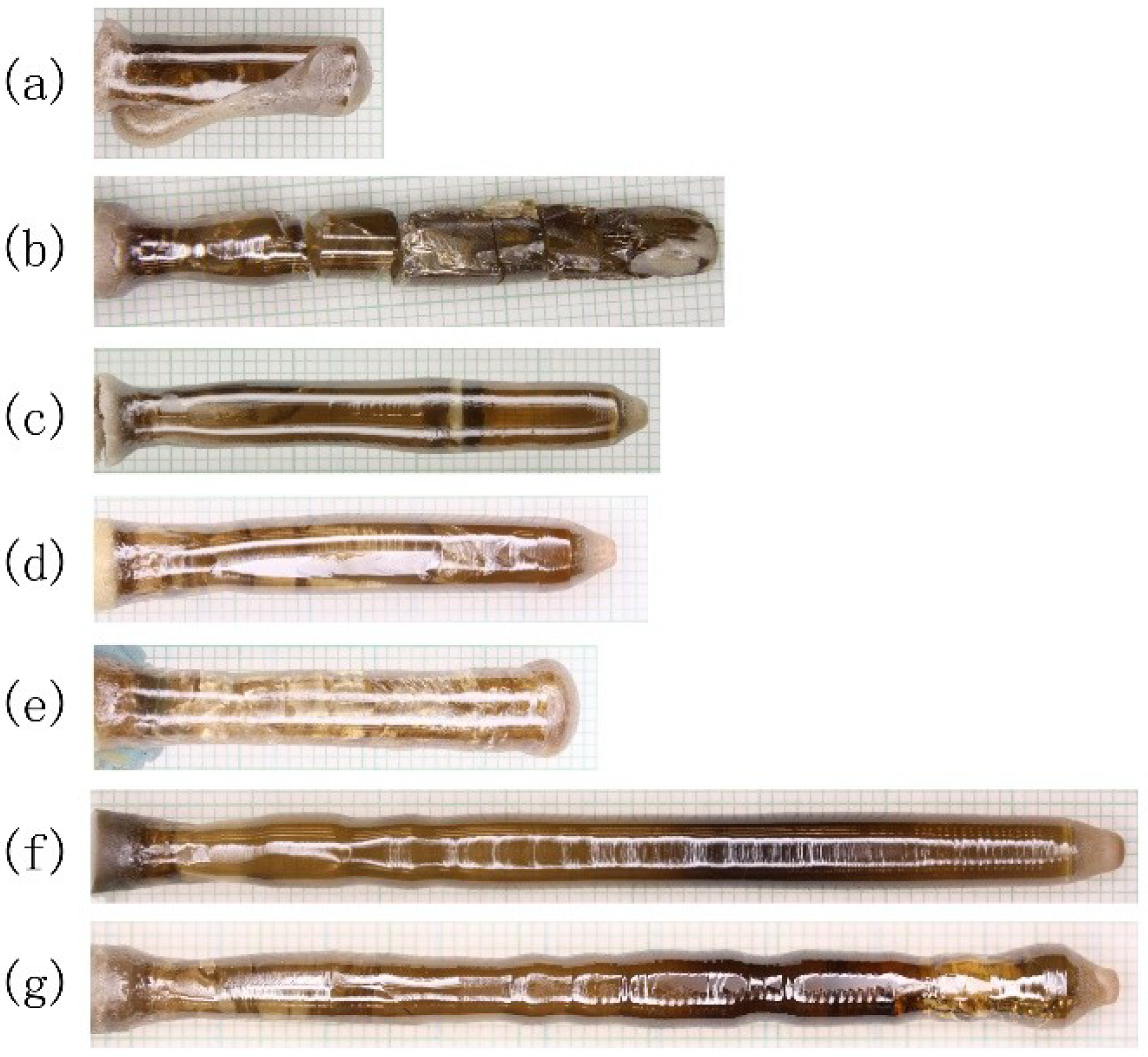
Figure 1 shows some of the as-grown Y2Ti2O7 crystals obtained by using different lamps and different atmospheric conditions, i.e., different gases and various pressures. The as-grown crystals shown in Figure 1a–f were obtained at the conditions of samples #1 to #7 in Table 1, respectively. The crystals shown in Figure 1a,b,e are samples where the zones collapsed due to crystal tilting, crystals cracking into pieces or an increase of input power. Short crystals with a length of less than 5 cm, as shown in Figure 1a–e, are uniform in color. However, the crystals with a length of about 7 cm, in Figure 1f,g, are semi-transparent, dark, and transparent from the tip (the end of growth) to end (the beginning of growth). The dark regions are almost in the same position, 1.5–3.5 cm from the tips. The formation mechanism of the dark region of as-grown crystals is not clear, but it is more likely related to the long-time exposure of this part of a crystal to an intermediate temperature range (annealing) during slow cooling, rather than to the evolution of the composition of FZ during growth. Before a possible mechanism is confirmed, other optical factors that may cause a change of color of the crystals should be excluded. This issue will be discussed in another paper [22]. In this work, our main aim is the observation of striations. Several Y2Ti2O7 crystals were cut into slices, polished and analyzed under visual and polarized light.
3.2. The Striations and the Growth Interface
3.2.1. Observation of Striations of As-Grown Crystals
Figure 2 shows polariscopic photos of the slices from as-grown Y2Ti2O7 crystals grown using different gases with various pressures and different seed-rod rotation speeds. Figure 2a is a picture of a slice cut from sample #1 (Figure 1a). The dark and bright stripes are the growth striations resulting from periodic heating and cooling. The tip of the spilled crystal displays the growth interface shape. The striations have the same shape as the crystal tip. Therefore, the striation can be used as an indicator of the growth interface.
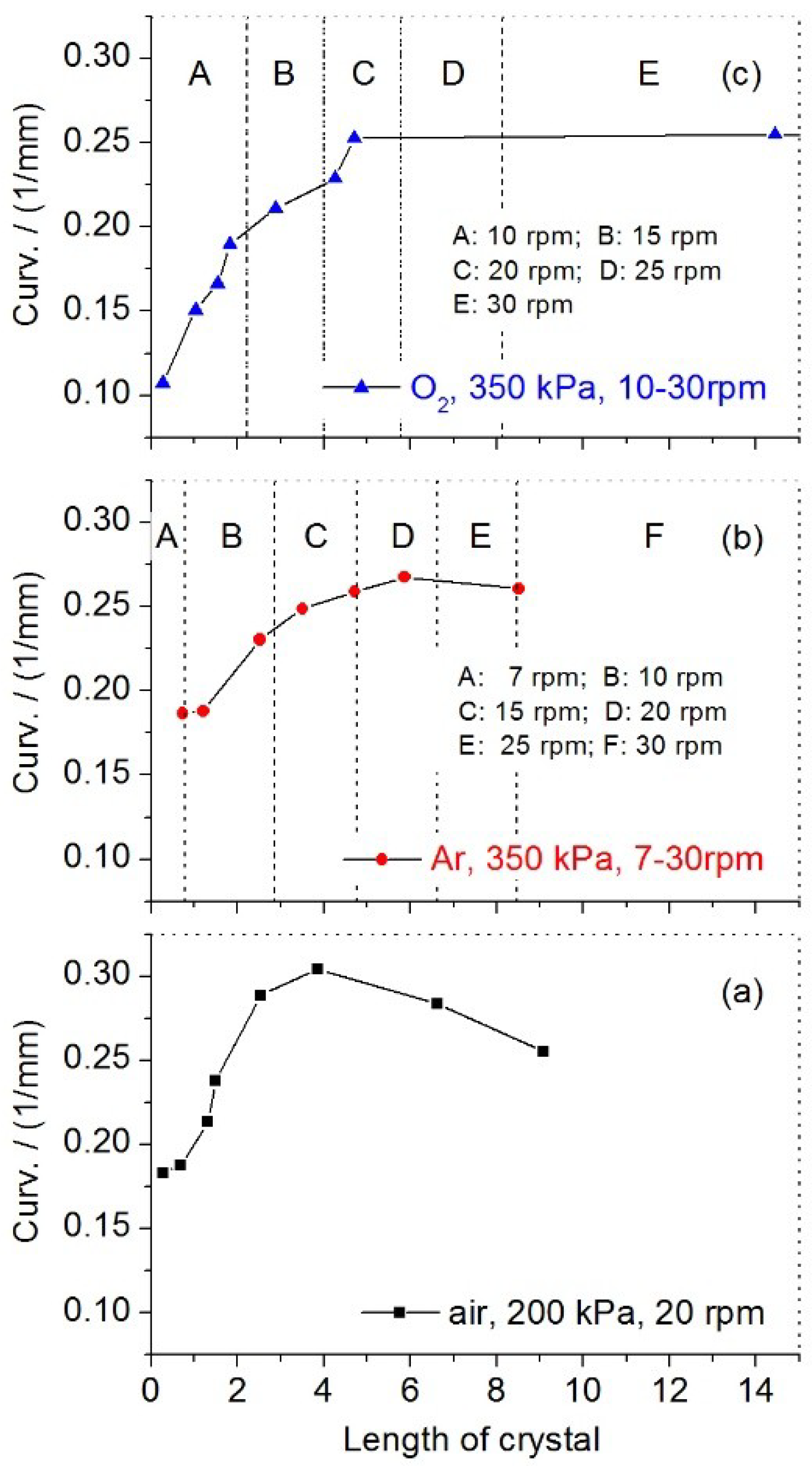
Figure 2b–d show images of striations as a function of crystal length for crystals grown at different atmospheres, i.e., air, argon, and oxygen, respectively. For Y2Ti2O7, a single grain crystal can be obtained after about 7 mm of growth. Usually, after the first 5 mm of stable growth, we change the seed-rod rotation speed from a relatively low value (7 rpm) to a high value (30 rpm). The magnified picture (not shown in this paper) shows that the shapes of striations change along the crystal length. The curvatures versus crystal length are shown in Figure 3. The curvatures are measured according to the following steps: (1) copy the picture into AutoCAD software; (2) according to the size of the crystal, adjust the picture into 1:1 in scale; (3) draw a circle that its arc should match the striation; (4) get the radius value of the circle, (5) the reciprocal value of the circle radius is the measured curvature. From the beginning of growth to a length of 5 mm, the curvature of the striations increases with the crystal length but is not influenced by the rod rotation speed or the ambient gases (air, Ar, and O2) and their pressure. Subsequently, after growing 5 mm from the beginning of the process of solidification, the curvatures decrease (Figure 3a,b) and we observe a plateau (Figure 3c).
In other words, these curves show a correlation between the shape of the growth interface and the crystal length. This relationship results from the changes in the thermal flow distribution through the crystallization front as the length of the crystal increases. An accompanying qualitative analysis is discussed in the following Section 3.2.2 and Section 3.2.3.
3.2.2. Overheating of the Floating Zone Resulting from Heat Exchange
During crystal growth, while ignoring the convection heat exchange between the rods (including a part of the liquid bridge) and the ambient gas, the net radiation heat delivered to the floating zone (H0)* (*heat is used in the sense of heat per time unit) should be described by the heat (Hf) conducted out by feed-rod and the heat (Hs) conducted out by the seed-rod (or as-grown crystal cylinder). For a stable state all three parts are in balance and can be described by the equation:
The above relation does not uniquely determine a solution. Assuming that the temperature of the cool end of feed-rod (Tf) is constant and the heat Hf is given by Fourier’s law of heat conduction,
where χ is the average thermal conductivity of the feed-rod including half of the liquid bridge, A is the area of the cross-section of the feed-rod, Tz is the average temperature of the floating zone (the liquid bridge). In the stable growth state, the amount of heat (H0) delivered to the liquid is constant. If the heat Hs increases from Hs to Hs′, according to Equations (1) and (2), the heat Hf should decrease to Hf′, and Tz should likewise decrease to Tz′, which means that the floating zone has a lower degree of overheating. If the heat Hs decreases from Hs to Hs″, the average temperature Tz″ of the floating zone is higher than Tz, and the floating zone has a higher degree of overheating.
H0 = Hf + Hs
Hf = χA(Tz − Tf)
The analysis discussed above does not consider the change of the net radiated heat (H0), i.e., H0 is considered to be constant during crystal growth. When the zone is heated to a high temperature, according to Stefan’s T4 law, H0 decreases accordingly and the temperature of the floating zone tends to decrease too. Thus the zone is not overheated to a temperature as high as Tz″ expected from the Equation (2), but rather to a temperature T (Tz < T < Tz″).
The above description does not take into account details, like convection heat exchange between the rods and the ambient gas, radiation emission from rods, etc., but these processes are complex and a more complex analysis will be difficult and is beyond scope of this paper. Even if the analysis is oversimplified, it explains how changes (evolution) in thermal-conductivity of feed-rod and seed-rod can influence the maximum temperature (and more general temperature distribution) in a liquid bridge.
3.2.3. Overheating and Striation Curvatures
The thermal conductivity of the ceramic rod (χcer.) is smaller than that of the crystal (χcry.) of the same composition. During the growth of crystals, the thermal conductivity of the feed-rod is lower and nearly constant while the effective thermal conductivity of the seed-rod (crystal) is increasing according to its length. According to Equations (1) and (2), the heat Hs increases, the heat Hf decreases and the floating zone temperature Tz is lowered. The overheating in the zone affects the shape of the solid-liquid interface, which manifests itself in changes of the striation’s shape. A lower positive temperature gradient profile is apt to the convex interface, so the curvatures increase in the early stage of crystal growth, as shown in Figure 3.
It is worth stressing, that the changes in temperature distribution in the floating zone influence position (and shape) of both the melting interface (liquid-feed-rod) and crystallization front. This can compromise the basic stability of the liquid bridge, so the operator needs to correct process parameters to avoid catastrophic process termination—“spill”.
3.3. The Effects of the Supplied Power on the Striation of the Y2Ti2O7 Crystal
Figure 4 shows the visual light and polarized light photos of the tips of as-grown crystals obtained under different degrees of overheating. For the as-grown crystal with a low overheating degree (see Figure 4a–c), the striation shape is almost the same as the growth interface, which has a radius of 4.3 mm. Under high overheating conditions the striation is less convex and the growth interface has the radius of 5.9 mm, as shown in Figure 4d–f. This result indicates that the overheating degree of the floating molten zone affects the shape of the growth interface under constant conditions unless the supplied power is adjusted by the operator. This result agrees well with our results discussed in Section 3.2 and with other published results [17].
3.4. The Effects of Rotation Speed on the Striation of the Y2Ti2O7 Crystal
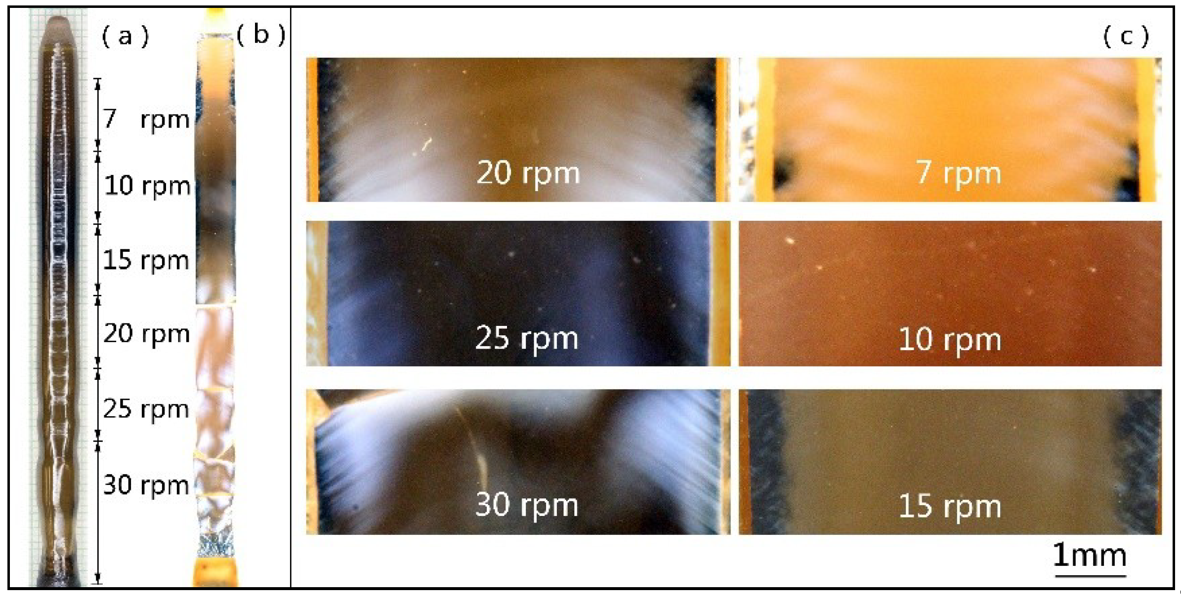
For this part of our experiments, the growth parameters were kept constant, except for the seed-rod rotation speed. The feed-rod rotation speed was fixed at 7 rpm; the temperature Tf is assumed to be constant. The seed-rod (growing crystal) rotation speed was changed in steps from 30 rpm to 7 rpm. The growth is performed and the analysis is done. Figure 5a shows the picture of the as-grown crystal. The dark region is at 1.5–3.5 cm from the as-grown crystal tip. The dependence of the striation shape on the seed-rod rotation speed was observed under polarized light, as shown in Figure 5b. Changes in the striations pattern with seed-rod rotation speed are presented in Figure 5c. The curvature of the striations decreases with decreasing seed-rod rotation speed, as shown in Figure 6. The striations have a concave shape at a rotation speed of 7 rpm. For a rotation speed of 10 and 15 rpm, clear striations were not visible due to the darkness of crystals. The results of another growth display clear striations under lower rotation speeds, as shown in Figure 7. The striation shape is less convex for 7 rpm than for 15 rpm.
Striation curvature is dependent on the seed-rod rotation speed, with it decreasing from 30 to 7 rpm, the curvature gradually changes from 0.27, 0.24, 0.22, 0.21, 0.20 to 0.17 mm−1 (the value of 0.17 is for the convex part of striations near the edges at 7 rpm). This suggests that the degree of overheating in the floating zone increases with decreasing of the seed-rod rotation speed.
The dependence of the striation or interface shape of rutile single crystals on the rotation speed was investigated experimentally by Higuchi et al. [23]. Their results showed that the growth interface is much flatter under a high rotation speed (e.g., 40 rpm), which contrary to our results is discussed above. Why does such a big difference exist? The growth rate and the interface shape are strongly determined by transport of the latent heat during crystallization. The rotation speed is one of many factors which influence the heat exchange, mainly by controlling forced convection in the liquid bridge. The rotation speed of the seed-rod (or as-grown crystal cylinder) affects not only the convection in the liquid zone but also the dissipation of the latent heat of crystallization, altogether, shaping the isotherm of crystallization temperature.
Rotation of a seed-rod (and counter-rotation of a feed-rod) introduce another effect. The heating process in the OFZ (in the configuration of horizontally distributed heating lamps with mirrors) causes significant overheating of the liquid bridge in the region where the focused light is dissipating in the liquid. Accordingly, the liquid temperature in-between “hot spots” is lower. The rotation of the liquid bridge caused by the seed-rod is partially averaging liquid temperature, but for lower rotation, one can expect significantly higher temperature gradients than for a higher rotation. During crystal growth, in the radial direction on the horizontal plane near the S–L interface, the as-grown crystal experiences periods of weak heating alternated with strong heating due to the layout of lamps. The temperature is undergoing continuous and periodic oscillations from a strong heating regime (with a higher temperature, TH) to weak heating regime (with a lower temperature, TL) and amplitude of this oscillation depends on the rotation rate (low rotation–high amplitude). At the lower rotation speed, the temperature TL may approach the lower value. The heat extracted by the seed-rod decreases according to Equation (3)
where T0 is the temperature of the cool end of a seed-rod, constant, i.e., the “surrounding” temperature. Similarly analyzing the discussion above, in the range of low values of rotation speed, e.g., 7–30 rpm, the exchange heat (Hs) dissipated by the as-grown crystal cylinder decreases with the decreasing rotation speed and the degree of overheating of molten zone subsequently increases. If a convex interface advances towards the zone, it is melted back by a higher positive temperature gradient and a less convex interface shape is formed. However, at a high rotation speed (e.g., 40 rpm), the exchange heat Hs possibly approaches a constant value, so the interface shape is strongly affected by the convection in the melt which is related to the seed-rod rotation and temperature gradients in the liquid bridge. This is a simplified description, and in this extremely complex thermal environment, it is impossible to predict the thermal field and flows (heat and liquid) without advanced numerical analysis. Such modeling is beyond the scope of our purely experimental paper.
HS = χA(TL − T0)
4. Summary
Several Y2Ti2O7 single crystals were grown by the optical floating zone method. Striations in as-grown crystals were observed under polarized light. The striations and the growth interface have the same shape and the evolution of the shape with the growth of the crystal and changes of growth parameters indicates that the analysis of striations can be used to describe the growth interface. It is found that the degree of overheating of the floating zone affects the shape of the growth interface. A higher positive temperature gradient profile prohibits the convex interface from advancing forward, and a less convex interface shape is formed. The high overheating cases were observed in the following experiments:
(1) In the initial state of Y2Ti2O7 growth leading to the selection of a single grain, the growth interface shape depends on the thermal conductivity of the seed ceramic rod. A less convex interface with low curvature is obtained at a high overheating degree at the beginning of growth.
(2) During the growth of Y2Ti2O7 single crystals, the overheating degree increases with increasing power. Under high overheating conditions, Y2Ti2O7 single crystals with a less convex growth interface are obtained.
(3) After the initial state of Y2Ti2O7 growth, with decreasing rotation speed of seed-rod from 30 rpm to 7 rpm, the curvature of striation decrease, and the shape of growth interface changes from convex to less convex and even to a concave one.
Author Contributions
Conceptualization, C.L., A.D. and H.A.D.; Data curation, C.L.; Formal analysis, C.L.; Funding acquisition, W.J., B.D.G. and H.A.D.; Investigation, C.L. and H.A.D.; Methodology, C.L., A.D. and H.A.D.; Supervision, W.J. and H.A.D.; Writing—original draft, C.L.; Writing—review & editing, A.D., W.J., B.D.G. and H.A.D.
Funding
This work was supported by the National “973” Project (No. 2011CB610406) of China, China Scholarship Council (No. 201406295058) and the Brockhouse Institute for Materials Research. Work at McMaster University was supported by NSERC of Canada.
Acknowledgments
We are grateful to Timothy Munsie, Casey Marjerrison, and Dalini Maharaj for their help for crystal growth experiments.
Conflicts of Interest
The authors declare no conflict of interest.
References
- Kim, P.; Jones, S.C.; Hotchkiss, P.J.; Haddock, J.N.; Kippelen, B.; Marder, S.R.; Perry, J.W. Phosphonic Acid-Modified Barium Titanate Polymer Nanocomposites with High Permittivity and Dielectric Strength. Adv. Mater. 2007, 19, 1001. [Google Scholar] [CrossRef]
- Shlyakhtina, A.; Shcherbakova, L. New solid electrolytes of the pyrochlore family. Russ. J. Electrochem. 2012, 48, 1. [Google Scholar] [CrossRef]
- Higashi, M.; Abe, R.; Sugihara, H.; Domen, K. Photocatalytic Water Splitting into H2 and O2 over Titanate Pyrochlores Ln2Ti2O7 (Ln = Lanthanoid: Eu–Lu). Bull. Chem. Soc. Jpn. 2008, 81, 1315. [Google Scholar] [CrossRef]
- Johnson, M.B.; James, D.D.; Bourque, A.; Dabkowska, H.A.; Gaulin, D.B.; White, M.A. Thermal properties of the pyrochlore, Y2Ti2O7. J. Solid State Chem. 2009, 182, 725. [Google Scholar] [CrossRef]
- Mani, R.; Fischer, M.; Joy, J.E.; Gopalakrishnan, J.; Jansen, M. Ruthenium(IV) pyrochlore oxides: Realization of novel electronic properties through substitution at A- and B-sites. Solid State Sci. 2009, 11, 189. [Google Scholar] [CrossRef]
- Su, W.P.; Lee, Y.H.; Hsieh, C.T.; Sheu, H.S.; Lee, J.S.; Chiang, Y.P.; Kao, H.-C.I. Effect of Li2O Addition on the Preparation of (Y2-yLiy)Ti2O7-y. J. Chin. Chem. Soc. 2009, 56, 1112. [Google Scholar] [CrossRef]
- Straehan, D.M.; Scheele, R.D.; Buek, E.C.; Icenhower, J.P.; Kozelisky, A.E.; Sell, R.L.; Elovich, R.J.; Buchmiller, W.C. Radiation damage effects in candidate titanates for Pu disposition: Pyrochlore. J. Nucl. Mater. 2005, 345, 109. [Google Scholar] [CrossRef]
- Quilliam, J.A.; Yaraskavitch, L.R.; Dabkowska, H.A.; Gaulin, B.D.; Kycia, J.B. Dynamics of the magnetic susceptibility deep in the Coulomb phase of the dipolar spin ice material Ho2Ti2O7. Phys. Rev. B 2011, 83, 094424. [Google Scholar] [CrossRef]
- Ruff, J.P.C.; Islam, Z.; Clancy, J.P.; Ross, K.A.; Nojiri, H.; Matsuda, Y.H.; Dabkowska, H.A.; Dabkowski, A.D.; Gaulin, B.D. Magnetoelastics of a Spin Liquid: X-Ray Diffraction Studies of Tb2Ti2O7 in Pulsed Magnetic Fields. Phys. Rev. Lett. 2010, 105, 077203. [Google Scholar] [CrossRef] [PubMed]
- Gardner, J.S.; Gingras, M.J.; Greedan, J.E. Magnetic pyrochlore oxides. Rev. Mod. Phys. 2010, 82, 53. [Google Scholar] [CrossRef]
- Antonov, V.A.; Arsenev, P.A. Spectroscopic properties of single crystals of rare earth titanates. Phys. Status Solidi A 1976, 35, K169. [Google Scholar] [CrossRef]
- Antonov, V.A.; Arsenev, P.A.; Petrova, D.S. Spectroscopic properties of the Nd3+ ion in Y2Ti2O7 and Gd2Ti2O7 monocrystals. Phys. Status Solidi A 1977, 41, K127. [Google Scholar] [CrossRef]
- Yan, D.; Qiu, J.B.; Song, Z.G.; Zhou, D.C.; Yu, X.; Yang, Y.; Wang, R.F.; Wu, H.J.; Yin, Z.Y.; Yang, Z.W. Blue and Green Upconversion Emission Modification in Tb, Yb Co-Doped Y2Ti2O7 Inverse Opal. In Proceedings of the Symposium on Photonics and Optoelectronics (SOPO), Shanghai, China, 21–23 May 2012. [Google Scholar]
- Matteucci, F.; Cruciani, G.; Dondi, M.; Baldi, G.; Barzanti, A. Crystal structural and optical properties of Cr-doped Y2Ti2O7 and Y2Sn2O7 pyrochlores. Acta Mater. 2007, 55, 2229. [Google Scholar] [CrossRef]
- Feng, W.L.; Xue, J.Y. Theoretical investigation of optical spectra and covalent effect of Cr4+ in Y2Ti2O7 and Y2Sn2O7. Phys. B 2012, 407, 2344. [Google Scholar] [CrossRef]
- Morrison, C.A. Angular Momentum Theory Applied to Interactions in Solids; Springer Science & Business Media: Berlin, Germany, 2012; p. 124. [Google Scholar]
- Hossain, M.M.; Watauchi, S.; Naga, M.; Tanaka, I. Effects of lamp power and mirror position on the interface shape of the silicon molten zone during infrared convergent heating. CrystEngComm 2014, 16, 4619. [Google Scholar] [CrossRef]
- Sarker, M.A.R.; Watauchi, S.; Nagao, M.; Watanabe, T.; Shindo, I.; Tanaka, I. Effects of tilting mirrors on the solid–liquid interface during floating zone growth using tilting-mirror-type infrared-heating image furnace. J. Cryst. Growth 2010, 312, 2008. [Google Scholar] [CrossRef]
- Sarker, M.A.R.; Watauchi, S.; Nagao, M.; Watanabe, T.; Shindo, I.; Tanaka, I. Effects of the diameter of rutile (TiO2) single crystals grown using tilting-mirror-type infrared heating image furnace on solid–liquid interface and etch pit density. J. Cryst. Growth 2011, 317, 135. [Google Scholar] [CrossRef]
- Watauchi, S.; Sarker, M.A.R.; Nagao, M.; Tanaka, I.; Watanabe, T.; Shindo, I. Crystal growth of rutile by tilting-mirror-type floating zone method. J. Cryst. Growth 2012, 360, 105. [Google Scholar] [CrossRef]
- Dabkowska, H.A.; Dabkowski, A.B. Optical Floating Zone—Complementary Crystal Growth Technique for New Classes of Oxide Materials. In Handbook of Crystal Growth; Nishinaga, T., Rudolph, P., Eds.; Elsevier: Amsterdam, The Netherlands, 2015; Volume II, p. 283. [Google Scholar]
- Liu, C.Y.; Dabkowski, A.; Jie, W.Q.; Gaulin, B.D.; Dabkowska, H.A. XRD Analysis of RE2Ti2O7 Crystals Grown by Optical Floating Zone Method. Crystals 2019. submitted. [Google Scholar]
- Higuchi, M.; Kodaira, K. Solid-liquid interface shapes in the floating zone growth of rutile single crystals. Mater. Res. Bull. 1994, 29, 545. [Google Scholar] [CrossRef]
Figure 1.
Pictures of as-grown Y2Ti2O7 crystals. As-grown crystals shown in (a–g) were obtained under conditions listed in Table 1, respectively. The tips of as-grown crystals are on the right side in photos.
Figure 1.
Pictures of as-grown Y2Ti2O7 crystals. As-grown crystals shown in (a–g) were obtained under conditions listed in Table 1, respectively. The tips of as-grown crystals are on the right side in photos.

Figure 2.
Polariscopic photographs of slices cut from the central part of as-grown Y2Ti2O7 crystals. (a) For sample # 1, (b) for sample #2, (c) for sample #3, and (d) for sample #4.
Figure 2.
Polariscopic photographs of slices cut from the central part of as-grown Y2Ti2O7 crystals. (a) For sample # 1, (b) for sample #2, (c) for sample #3, and (d) for sample #4.

Figure 3.
The evolution of the curvature of the striations of as-grown Y2Ti2O7 crystals obtained at different conditions: (a) for sample #2, (b) for sample #3, and (c) for sample #4.
Figure 3.
The evolution of the curvature of the striations of as-grown Y2Ti2O7 crystals obtained at different conditions: (a) for sample #2, (b) for sample #3, and (c) for sample #4.

Figure 4.
The dependency of curvature of Y2Ti2O7 crystal striations from overheating (nominal input power). Sample #1 (2.55 kW, low overheating): left column. (a) Picture of the tip of the as-grown crystal, (b) polarized picture of the tip of the central slice, (c) an arc matched the striation. Sample #5 (2.75 kW, high overheating): right column. (d) Picture of the tip of the central slice, (e) polarized picture of the tip of the central slice, (f) an arc matched the striation.

Figure 5.
The picture as-grown Y2Ti2O7 crystal and the image of its slice in polarized light. (a) Picture of sample #6, (b) polarized picture of the tip of the central slice, and (c) amplified pictures selected from (b) obtained at a different rotation speed. Corresponding rotation rates for different crystal parts are labeled.

Figure 6.
Correlation between striation curvature and seed-rod rotation speed (for sample #6).

Figure 7.
The polarized light images of as-grown Y2Ti2O7 slice (sample #7): (a) 7 rpm, R = 4.99mm, and (b) 15 rpm, R = 3.92mm.
Figure 7.
The polarized light images of as-grown Y2Ti2O7 slice (sample #7): (a) 7 rpm, R = 4.99mm, and (b) 15 rpm, R = 3.92mm.


Table 1.
Condition of Y2Ti2O7 crystal growths.
| Sample | Lamps (a) | Input Power (kW, nominal) | Feed Speed (mm/h) | Growth Speed (b) (mm/h) | Seed-Rod Rotation (c) (rpm) | Atmosphere | Pressure (kPa) |
|---|---|---|---|---|---|---|---|
| #1 | 2 × 1.5 kW | 2.55 | 6.0–6.4 | 6.5 | 7–30 | Air | 100 |
| #2 | 2 × 1.5 kW | 2.7–2.73 | 5.9–6.4 | 6.5–7.3 | 20 | Air | 200 |
| #3 | 2 × 1.5 kW | 2.67–2.69 | 5.6–6.9 | 7.0–7.3 | 7–30 | Ar (d) | 350 |
| #4 | 2 × 1.5 kW | 2.72–2.73 | 6.2–7.0 | 7.0–7.2 | 7–30 | O2 | 350 |
| #5 | 2 × 1.5 kW | 2.72–2.73 | 6.9–7.0 | 7.0–7.3 | 7–30 | O2 | 200 |
| #6 | 2 × 2 kW | 2.94 | 7.4 | 7.7 | 7–30 | O2 | 140 |
| #7 | 2 × 2 kW | 2.83 | 7.0 | 7.8 | 7–30 | O2 | 140 |
(a): Power distribution within the focal plane is different for halogen lamps with different nominal power. (b): For a stable growth state, this parameter is controlled in the range of ±0.2. (c): Feed-rod counter-rotation speed is fixed at 7 rpm, except for sample #2 where it is 10 rpm. (d): High-purity argon with maximum content of O2 2ppm and H2O 3ppm was used.
© 2019 by the authors. Licensee MDPI, Basel, Switzerland. This article is an open access article distributed under the terms and conditions of the Creative Commons Attribution (CC BY) license (http://creativecommons.org/licenses/by/4.0/).
Share and Cite
MDPI and ACS Style
Liu, C.; Dabkowski, A.; Jie, W.; Gaulin, B.D.; Dabkowska, H.A. Optical Observation of Striations in Y2Ti2O7 Single Crystals. Crystals 2019, 9, 233. https://doi.org/10.3390/cryst9050233
AMA Style
Liu C, Dabkowski A, Jie W, Gaulin BD, Dabkowska HA. Optical Observation of Striations in Y2Ti2O7 Single Crystals. Crystals. 2019; 9(5):233. https://doi.org/10.3390/cryst9050233
Chicago/Turabian StyleLiu, Changyou, Antoni Dabkowski, Wanqi Jie, Bruce D. Gaulin, and Hanna A. Dabkowska. 2019. "Optical Observation of Striations in Y2Ti2O7 Single Crystals" Crystals 9, no. 5: 233. https://doi.org/10.3390/cryst9050233
Note that from the first issue of 2016, this journal uses article numbers instead of page numbers. See further details here.