Analysis of Leaky Modes in Photonic Crystal Fibers Using the Surface Integral Equation Method


Department of Electrical Engineering, I-Shou University, Kaohsiung 84001, Taiwan
Crystals 2018, 8(4), 177; https://doi.org/10.3390/cryst8040177
Submission received: 1 March 2018
/
Revised: 14 April 2018
/
Accepted: 14 April 2018
/
Published: 19 April 2018
(This article belongs to the Special Issue Photonic Crystal Fiber)
Abstract
:A fully vectorial algorithm based on the surface integral equation method for the modelling of leaky modes in photonic crystal fibers (PCFs) by solely solving the complex propagation constants of characteristic equations is presented. It can be used for calculations of the complex effective index and confinement losses of photonic crystal fibers. As complex root examination is the key technique in the solution, the new algorithm which possesses this technique can be used to solve the leaky modes of photonic crystal fibers. The leaky modes of solid-core PCFs with a hexagonal lattice of circular air-holes are reported and discussed. The simulation results indicate how the confinement loss by the imaginary part of the effective index changes with air-hole size, the number of rings of air-holes, and wavelength. Confinement loss reductions can be realized by increasing the air-hole size and the number of air-holes. The results show that the confinement loss rises with wavelength, implying that the light leaks more easily for longer wavelengths; meanwhile, the losses are decreased significantly as the air-hole size d/Λ is increased.
1. Introduction
Leaky modes are modes that propagate in the guide irradiating power and decay exponentially along the direction of propagation. In classical optical fibers, two types of leaky modes are known: tunneling leaky modes that arise because of the curvature of the boundary between the core and the cladding and refracting leaky modes that arise from the beams that fall within the boundary with angles smaller than the critical angle [1]. From historical records, the leaky mode concept was first described in 1956 by Marcuvitz [2], who noted the close analogy to quantum-mechanical tunneling. He stated that this solution to the wave equation gives a field representation in a center range with a complex propagation constant, but that the field becomes infinite at the infinite transverse spatial limit [3]. In 1961, Cassedy and Cohn obtained the first measurement of a leaky mode and confirmed the existence of a leaky wave due to a line current source above a grounded dielectric slab [4]. In general, we notice that leaky modes were first described in the context of the textbook by Snyder and Love [1]. The analysis of leaky modes has been practical for designing various photonic and optoelectronic devices, such as depressed inner cladding single-mode fibers [5,6,7], sensors [8,9,10], and bent fibers [11,12,13].
Photonic crystal fibers (PCFs), which are also called holey fibers or microstructured optical fibers, have aroused great attention since they have the attractive advantage of control of light [14,15,16]. PCFs consist of a single material, typically silica, with a lattice of multiple air-holes around the core running along the fiber axis. The cladding of the fiber is comprised of a two-dimensional periodic array of air-holes at the transverse section, and the core is a central defect formed by breaking the periodic structure. It is known that certain periodic structures with broken periodicity exhibit the phenomenon of light localization at defects [17]. The most common type of PCF is solid-core PCF because it is easy to fabricate. For solid-core PCFs, the guidance mechanism is due to modified total internal reflection, which is similar to what occurs in conventional fibers. PCFs exhibit a lot of remarkable properties, such as an endless single-mode, unusual chromatic dispersion effect, design flexibility, supercontinuum generation, an extremely large or small effective core area at the single-mode region, and high nonlinearity [18,19,20,21]. These distinctive features of PCFs have promising applications in a variety of fields, from communication fiber links to optoelectronic devices. In the solid-core PCFs that this paper will investigate, the modes that decay while propagating are referred to as leaky modes [22]. Since the refractive index profile of a solid-core PCF is similar to the W-type waveguide [3], there are no truly bound modes due to the PCF’s structure with outermost cladding of a high refractive index which is equal to that of the fiber core. Although light is mostly confined in the core of the PCF, some light can leak out through the channels between adjacent air-holes due to the cladding having a finite number of air-hole rings and so generally modes in PCFs are leaky. Therefore, confinement losses are unavoidable even with the nonexistence of material absorption or scattering losses. Computationally, confinement loss is modelled through determining the leaky mode solutions of the vector wave equation corresponding to a complex refractive index or propagation constant [22].
An efficient numerical approach based on the surface integral equation method (SIEM) [23,24,25,26] is used to examine the propagation properties of PCFs. The SIEM provides very accurate results that only need an extremely small number of unknowns. The SIEM studies PCFs that are composed of two homogeneous media and only needs to consider the fields at the interface between the two media. Consequently, the computational unknowns and the degrees of freedom can be significantly reduced, and the computational efficiency will be enhanced without the loss of accuracy. Nevertheless, these papers only focus on studying guided modes. In this paper, a fully vectorial algorithm based on the SIEM is developed for the analysis of leaky modes in PCFs. This allows for a significant expansion in the applied aspects of the SIEM.
In recent years, several numerical techniques have been applied to leaky modes of PCFs. In 2001, White et al. [27] calculated the confinement loss of a leaky mode by using the multipole method, which is used for the accurate computation of the complex propagation constant of PCFs with a finite number of air-holes, but it is confined to structures that only have circular holes. The finite element method (FEM) has successfully been used to model the leaky modes of PCFs [28,29,30]. FEM is accurate and versatile, but a large number of unknowns are unavoidably needed since the cross-section of PCFs must be discretized into many finite elements. Therefore, FEM requires extensive computing resources, such as memory and computing time. The beam propagation method is able to evaluate the confinement loss of leaky modes [31]; however, this method is numerically intensive and can present difficulties in distinguishing between modes with similar propagation constants.
In this work, there is proposed a fully vectorial algorithm based on the surface integral equation method that is able to calculate the confinement loss and complex effective refractive index of PCFs. The new algorithm can model the leaky modes of PCFs with a finite number of air-holes. It can analyze how the confinement loss by the imaginary part of the effective refractive index changes with air-hole size, the number of air-hole rings, and wavelength.
2. Surface Integral Equation Formulation
A photonic crystal fiber is described by two homogeneous regions that are the air in the holes and the silica in the background, respectively. Suppose F represents any field components in Cartesian coordinates, then F is the solution of the Helmholtz equation at every individual region:
where denotes the Laplacian operator for the transverse plane. Using Green’s formula, Equation (1) can be converted to a surface integral as:
where the Γ denotes the boundary contour of two homogeneous regions and d/dn denotes an inward normal derivative. The two-dimensional Green’s function is given by , in which is the zeroth Hankel function of the second kind. If Γ is smooth enough, the surface integral
can be acquired by moving the observation point to the boundary, where indicates the Cauchy principle value integral with the singularity at the point of being removed.
Here, k0 is the free space wave number; β is the propagation constant; and n is the refractive index of the homogeneous region. Note that k may be a real or pure-imaginary quantity in Ref. [23], but it can be in the form of a complex value due to the fact that β is also a complex value for a leaky mode in this paper. The fully vectorial algorithm for the modelling of leaky modes in photonic crystal fibers by solely solving for the complex propagation constants of the characteristic equation is presented. As complex root examination is the key technique in the solution, this new algorithm possesses this technique and can be utilized for solving the leaky modes of photonic crystal fibers. For leaky modes, the complex transverse wave number, k, is determined by
Because the transverse magnetic fields are continuous at a permittivity discontinuity, this way is of considerable convenience in utilizing the transverse magnetic fields (Hx and Hy), where the longitudinal fields (Hz and Ez) can be acquired respectively from the relations of and as
where Hn and Hl stand for the normal and the tangential components of the magnetic field, respectively. Meanwhile, d/dn and d/dl represent the partial derivatives along the normal and the tangential directions, respectively. Explicitly, from the coordinate transformation, Hn and Hl can be calculated by Hx and Hy as
Here, θ is the angle between the inward normal direction and the x axis. Therefore, a complete depiction of the entire guidance structure by Hx and Hy and their normal derivatives at the boundary can be obtained from Equations (6) and (7). From the integral Equations (2) and (3), the propagation characteristics and corresponding field distributions are acquired by matching the continuity of the Ez and Hz fields.
3. Numerical Result
To demonstrate the validity of the fully vectorial algorithm based on the SIEM, the confinement loss of an all-silica PCF depicted in Figure 1a is calculated. The air-hole pitch Λ is 6.75 μm, the air-hole diameter d is 5.0 μm, λ = 1.45 μm, and ns = 1.45. Figure 1b,c show the magnetic-field vector distribution of the real part and the field intensity distribution of the imaginary part, respectively, of the fundamental mode HE11 for a PCF of two air-hole rings. It also can solve the transverse field distributions of the real part and the imaginary part of the TE01, HE21, and TM01 modes (second-order mode) shown in Figure 2.
Table 1 shows a direct comparison of these modes with precise results obtained by the multipole method [27]. Each mode can be qualitatively examined by plotting the modal fields. The propagation constant, β, is related to the effective index of the propagation mode neff by β = (2π/λ)·neff. This algorithm yields the complex effective index, and thus the confinement losses can be calculated as follows [32]:
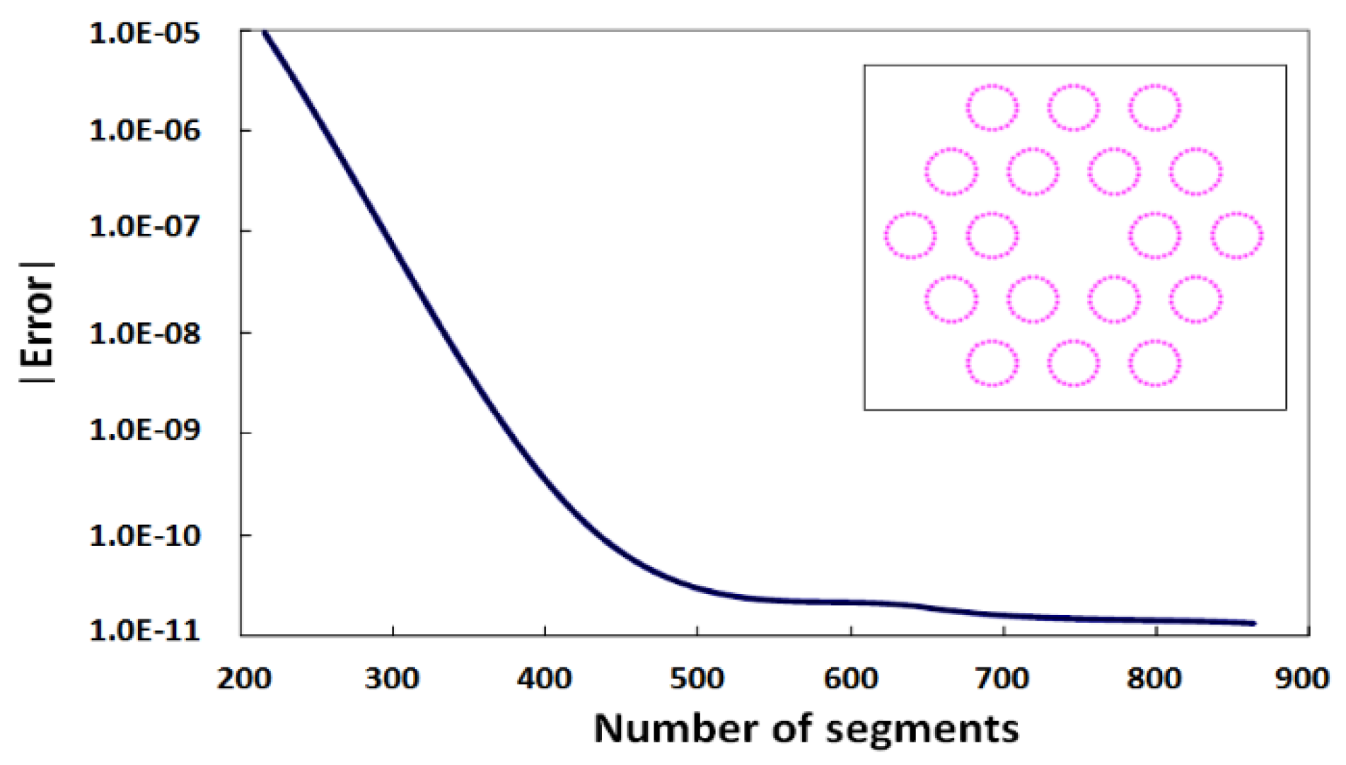
Clearly, the results show significant agreement between the present algorithm and the multipole method in both the confinement loss and complex effective index shown in Table 1. By convergence discussions, it will be able to obtain more accurate solutions and save computational time. Figure 3 shows the dependence of the relative error on the number of segments for the two air-hole ring configuration. The PCF cross-section is illustrated in the inset of Figure 3. The number of segments used for discretizing the boundary of all air-holes is an important numerical parameter relative to the accuracy and speed of calculation. It is shown that the relative error rapidly converges with a larger number of segments. From Figure 3, the error shows a small variation when the number of segments exceeds 400. In practice, the number of segments is 432 for modelling PCFs with 2 air-hole rings (18 air-holes), which discretize the boundary of each air-hole by 24 segments. Therefore, the total number of unknowns is only 28 × 18 × 2 = 864 for the 18 air-hole configuration (two unknowns, Hx and Hy, are assigned to each segment). The method has been beneficial in providing high computational efficiency.
Figure 4 shows the dispersion curves (complex effective index versus wavelength) of the fundamental leaky mode for a PCF with 2 air-hole rings (18 air-holes), where nsilica = 1.45 and d/Λ = 0.74 (air-hole size). Because of the finite number of rings of air-holes in the PCF, all modes are leaky and confinement losses can be acquired from the imaginary part of neff. This indicates that the location of the leaky modes is situated in the imaginary part of neff curve.
A schematic cross-section of a solid-core PCF with a hexagonal lattice of circular air-holes (refractive index nh (air) = 1) is shown in Figure 5a. It is formed by 4 air-hole rings (60 air-holes) embedded in silica (refractive index nsilica = 1.46), where d/Λ is the air-hole size (d is the air-hole diameter; Λ is the air-hole pitch). Figure 5b demonstrates the intensity profile of the fundamental leaky mode for the PCF with 2 air-hole rings (18 air-holes) having d/Λ = 0.4 and λ/Λ = 0.5. The hexagonal symmetry and the leakage due to the interruption of the air-holes can be clearly seen. The field confinement depends on the air-hole size and on the number of rings of air-holes. From the results of the mode class in Table 1, it can be found that the high-order modes have greater confinement loss than the fundamental mode.
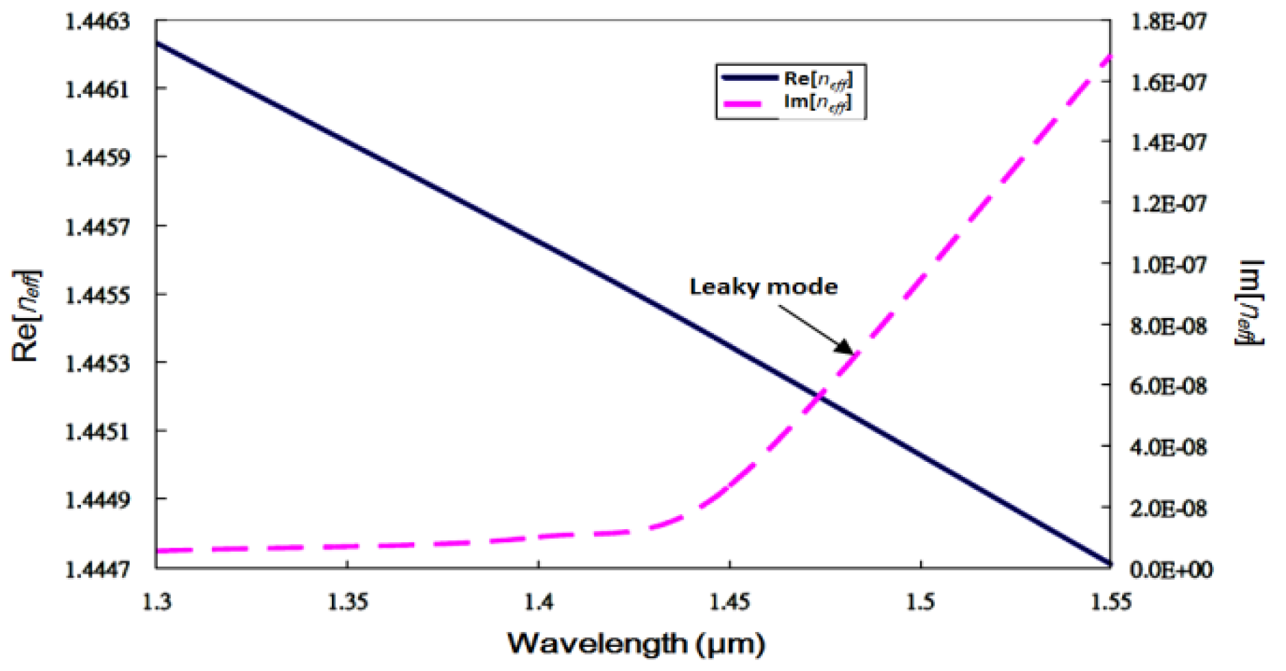
Figure 6 displays the wavelength responses of the neff of the fundamental mode for a 2 ring, 18 air-hole PCF with nsilica = 1.46 and d/Λ = 0.6. It is shown that the real part of neff decreases and the imaginary part of neff increases significantly as the wavelength is increased. Consequently, the confinement loss increases significantly in a wide wavelength range.
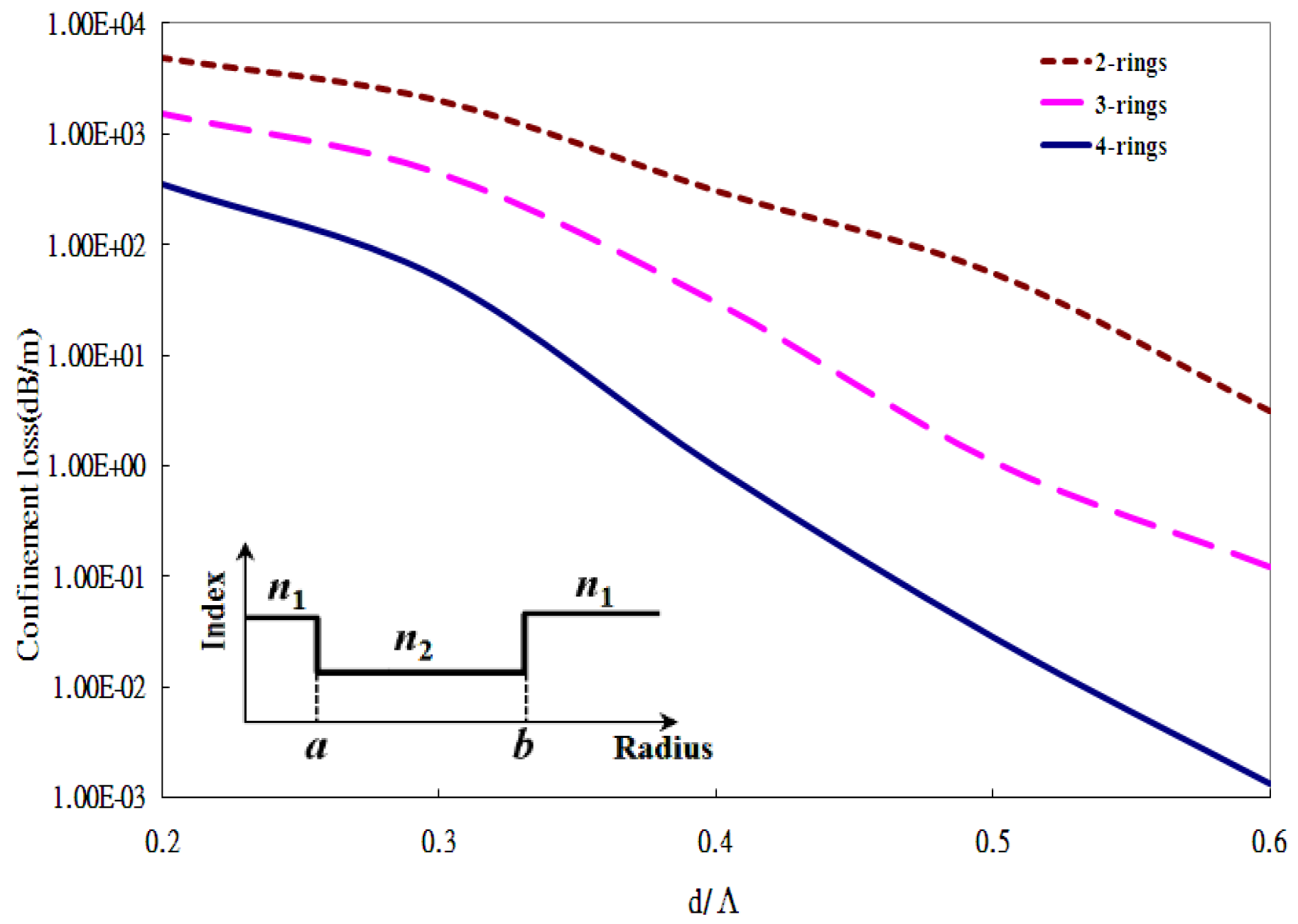
Figure 7 indicates the confinement losses of an all-silica PCF versus the air-hole size d/Λ for various numbers of air-hole rings at λ/Λ = 0.5. The confinement losses are monotonically decreased with the air-hole size and the number of air-hole rings. It can be seen that both a small air-hole size and a smaller number of air-holes induce a larger loss, but reduce rapidly if the air-hole size is enlarged or if a larger number of air-holes are employed. The inset of Figure 7 shows the refractive index profile. The refractive index n1 of the core is equal to the outer cladding, while the refractive index n2 of the inner cladding is smaller than n1. The radii of the core and inner cladding are indicated by a and b, respectively. Due to the PCF’s structure with outermost cladding of a high refractive index which is equal to the fiber core, there are no truly bound modes. Because of the low refractive index that air-holes offer the field confinement, the reduction of loss by increasing the air-hole size or the number of air-holes demonstrates that the inner cladding has a lower refractive index or a larger radius.
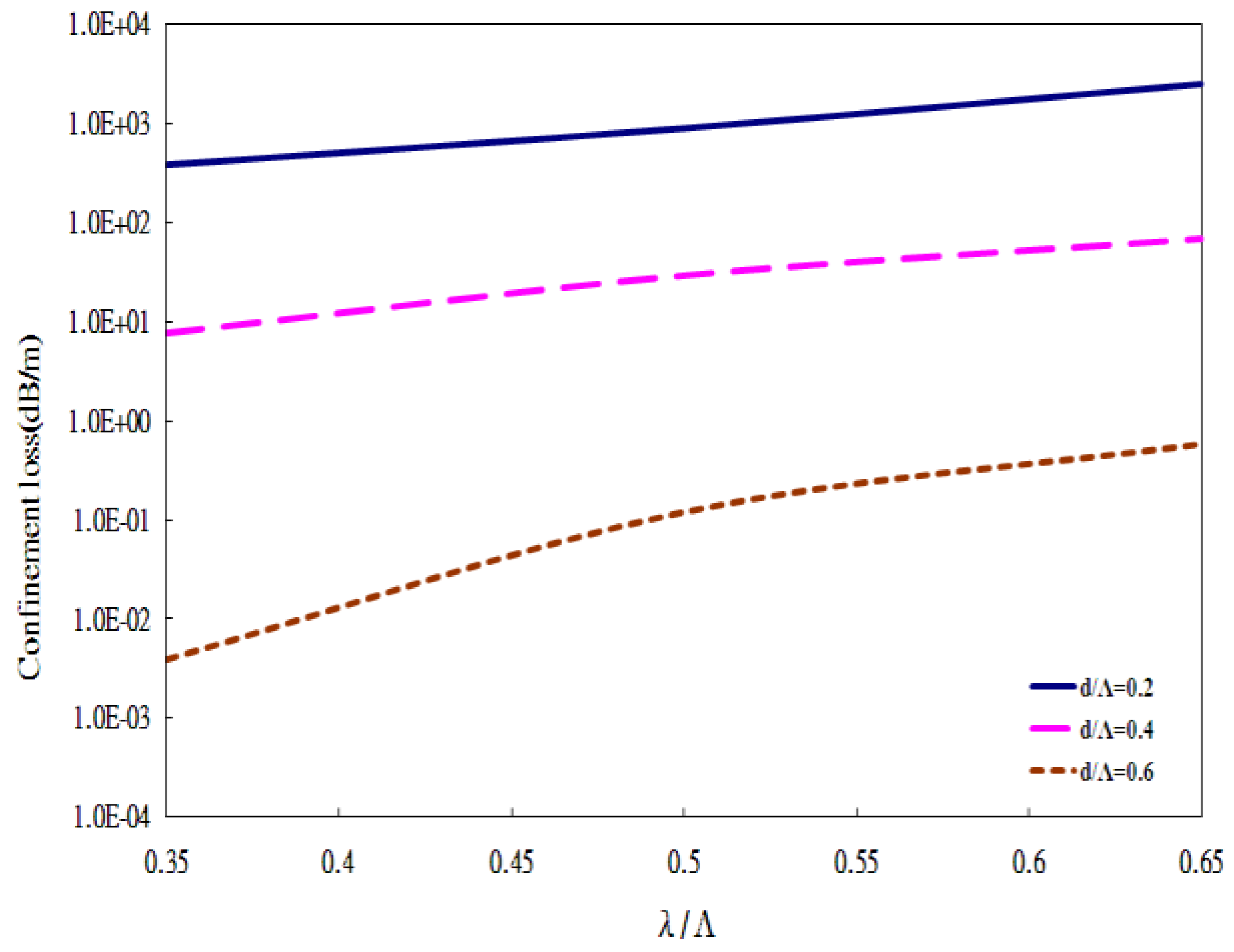
Figure 8 shows the loss spectra of various air-hole sizes d/Λ for a 3 air-hole ring (36 air-holes) PCF. They indicate that the confinement loss increases with wavelength, implying that a light leak increases more easily for longer wavelengths. It can be found that the losses decrease significantly as the air-hole size d/Λ is increased.
4. Conclusions
In this paper, there is presented a fully vectorial algorithm based on the surface integral equation method for modelling leaky modes in photonic crystal fibers by solely solving for complex propagation constants of characteristic equations. This method leads to an efficient code that is used to deal with a finite number of air-holes. It can be used for calculations of the full complex effective index and confinement loss of photonic crystal fibers. As complex root examination is the key technique in the solution, the new algorithm which possesses this technique can be used for solving the leaky modes of photonic crystal fibers. Due to the PCF’s structure with outermost cladding of a high refractive index which is equal to the fiber core, there are no truly bound modes so that all modes are leaky. The leaky modes of solid-core PCFs with a hexagonal lattice of circular air-holes are reported and discussed. The simulation results indicate how the confinement loss by the imaginary part of the effective index changes with air-hole size, the number of air-hole rings (or the number of air-holes), and wavelength. It can be understood that a reduction of confinement loss by increasing the air-hole size and the number of air-holes demonstrates that the inner cladding has a lower refractive index or a larger radius. The results show that the confinement loss rises with wavelength, implying that a light leak increases more easily for longer wavelengths; meanwhile, the losses decrease significantly as the air-hole size d/Λ is increased.
Acknowledgments
This work was partially supported by the I-Shou University, Taiwan (Republic of China), under grant numbers ISU-106-01-02A and ISU-107-01-02A. The author is grateful to his colleague Nai-Hsiang Sun for valuable discussions.
Conflicts of Interest
The author declares no conflict of interest.
References
- Snyder, A.W.; Love, J.D. Optical Waveguide Theory; Kluwer Academic Publishers: Norwell, MA, USA, 1983. [Google Scholar]
- Marcuvitz, N. On field representations in terms of leaky modes or eigenmodes. IRE Trans. Antennas Propag. 1956, 4, 192–194. [Google Scholar] [CrossRef]
- Hu, J.; Menyuk, C.R. Understanding leaky modes: Slab waveguide revisited. Adv. Opt. Photonics 2009, 1, 58–106. [Google Scholar] [CrossRef]
- Cassedy, E.S.; Cohn, M. On the existence of leaky waves due to a line source above a grounded dielectric slab. IRE Trans. Microw. Theory Tech. 1961, 9, 243–247. [Google Scholar] [CrossRef]
- Maeda, M.; Yamada, S. Leaky modes on W-fibers: Mode structure and attenuation. Appl. Opt. 1977, 16, 2198–2203. [Google Scholar] [CrossRef] [PubMed]
- Renner, H. Leaky-mode loss in coated depressed-cladding fibers. IEEE Photonics Technol. Lett. 1991, 3, 31–32. [Google Scholar] [CrossRef]
- Chou, C.C.; Sun, N.H. Analysis of leaky-mode losses for optical fibers. J. Opt. Soc. Am. B 2008, 25, 545–554. [Google Scholar] [CrossRef]
- Harris, J.; Lu, P.; Larocque, H.; Chen, L.; Bao, X. In-fiber Mach–Zehnder interferometric refractive index sensors with guided and leaky modes. Sens. Actuators B Chem. 2015, 206, 246–251. [Google Scholar] [CrossRef]
- Liu, Q.; Li, S.; Chen, H.; Fan, Z.; Li, J. Photonic crystal fiber temperature sensor based on coupling between liquid-core mode and defect mode. IEEE Photonics J. 2015, 7, 1–9. [Google Scholar] [CrossRef]
- Gao, R.; Lu, D.F.; Cheng, J.; Jiang, Y.; Jiang, L.; Qi, Z.M. Humidity sensor based on power leakage at resonance wavelengths of a hollow core fiber coated with reduced graphene oxide. Sens. Actuators B Chem. 2016, 222, 618–624. [Google Scholar] [CrossRef]
- Wang, P.; Semenova, Y.; Wu, Q.; Farrell, G.; Ti, Y.; Zheng, J. Macrobending single-mode fiber-based refractometer. Appl. Opt. 2009, 48, 6044–6049. [Google Scholar] [CrossRef] [PubMed]
- Lu, P.; Chen, Q. Femtosecond laser microfabricated fiber Mach–Zehnder interferometer for sensing applications. Opt. Lett. 2011, 36, 268–270. [Google Scholar] [CrossRef] [PubMed]
- Zhang, X.; Peng, W. Fiber optic refractometer based on leaky-mode interference of bent fiber. IEEE Photonics Technol. Lett. 2015, 27, 11–14. [Google Scholar] [CrossRef]
- Knight, J.C.; Birks, T.A.; Russell, P.S.J.; Atkin, D.M. All-silica single-mode optical fiber with photonic crystal cladding. Opt. Lett. 1996, 21, 1547–1549. [Google Scholar] [CrossRef] [PubMed]
- Broeng, J.; Mogilevstev, D.; Barkou, S.E.; Bjarklev, A. Photonic crystal fibers: A new class of optical waveguides. Opt. Fiber Technol. 1999, 5, 305–330. [Google Scholar] [CrossRef]
- Chiang, J.S.; Wu, T.L. Analysis of propagation characteristics for an octagonal photonic crystal fiber (O-PCF). Opt. Commun. 2006, 258, 170–176. [Google Scholar] [CrossRef]
- Ferrando, A.; Silvestre, E.; Miret, J.J.; Andres, P.; Andres, M.V. Vector description of higher-order modes in photonic crystal fibers. J. Opt. Soc. Am. A 2000, 17, 1333–1340. [Google Scholar] [CrossRef]
- Birks, T.A.; Knight, J.C.; Russell, P.S.J. Endlessly single-mode photonic crystal fiber. Opt. Lett. 1997, 22, 961–963. [Google Scholar] [CrossRef] [PubMed]
- Broderick, N.G.R.; Monro, T.M.; Bennett, P.J.; Richardson, D.J. Nonlinearity in holey optical fibers: Measurement and future opportunities. Opt. Lett. 1999, 24, 1395–1397. [Google Scholar] [CrossRef] [PubMed]
- Knight, J.C. Photonic crystal fibres. Nature 2003, 424, 847–851. [Google Scholar] [CrossRef] [PubMed]
- Cregan, R.F.; Mangan, B.J.; Knight, J.C.; Birks, T.A.; Russell, P.S.J.; Roberts, P.J.; Allan, D.C. Single-mode photonic bandgap guidance of light in air. Science 1999, 285, 1537–1539. [Google Scholar] [CrossRef] [PubMed]
- Zolla, F.; Renversez, G.; Nicolet, A.; Kuhlmey, B.; Guenneau, S.; Felbacq, D. Foundations of Photonic Crystal Fibres; Imperial College Press: London, UK, 2005. [Google Scholar]
- Su, C.C. A surface integral equations method for homogeneous optical fibers and coupled image lines of arbitrary cross sections. IEEE Trans. Microw. Theory Tech. 1985, 33, 1114–1119. [Google Scholar]
- Yang, W.; Gopinath, A. A boundary integral method for propagation problems in integrated optical structures. IEEE Photonics Technol. Lett. 1995, 7, 777–779. [Google Scholar] [CrossRef]
- Wu, T.L.; Chiang, J.S.; Chao, C.H. A novel approach for calculating the dispersions of photonic crystal fibers. IEEE Photonics Technol. Lett. 2004, 16, 1492–1494. [Google Scholar] [CrossRef]
- Chiang, J.S.; Wu, T.L. Analysis of an ultrashort PCF-based polarization splitter. J. Light. Technol. 2010, 28, 707–713. [Google Scholar] [CrossRef]
- White, T.P.; McPhedran, R.C.; de Sterke, C.M.; Botten, L.C.; Steel, M.J. Confinement loss in microstructured optical fibers. Opt. Lett. 2001, 26, 1660–1662. [Google Scholar] [CrossRef] [PubMed]
- Ferrarini, D.; Vincetti, L.; Zoboli, M.; Cucinotta, A.; Selleri, S. Leakage properties of photonic crystal fibers. Opt. Express 2002, 10, 1314–1319. [Google Scholar] [CrossRef] [PubMed]
- Zhang, Z.; Shi, Y.; Bian, B.; Lu, J. Dependence of leaky mode coupling on loss in photonic crystal fiber with hybrid cladding. Opt. Express 2008, 16, 1915–1922. [Google Scholar] [CrossRef] [PubMed]
- Gu, G.; Kong, F.; Hawkins, T.W.; Foy, P.; Wei, K.; Samson, B.; Dong, L. Impact of fiber outer boundaries on leaky mode losses in leakage channel fibers. Opt. Express 2013, 21, 24039–24048. [Google Scholar] [CrossRef] [PubMed]
- Steel, M.J.; Osgood, R.M., Jr. Polarization and dispersive properties of elliptical-hole photonic crystal fibers. J. Light. Technol. 2001, 19, 495–503. [Google Scholar] [CrossRef]
- Finazzi, V.; Monro, T.M.; Richardson, D.J. Small-core silica holey fibers: Nonlinearity and confinement loss trade-offs. J. Opt. Soc. Am. B 2003, 20, 1427–1436. [Google Scholar] [CrossRef]
Figure 1.
(a) Schematic of the solid-core photonic crystal fiber (PCF) with two air-hole rings, where Λ is the air-hole pitch, d is the air-hole diameter, and the background material is silica. (b) The transverse magnetic-field vector distribution of the real part, and (c) the field intensity distribution of the imaginary part of HE11 mode (fundamental mode) for the PCF with 2 air-hole rings (18 air-holes).
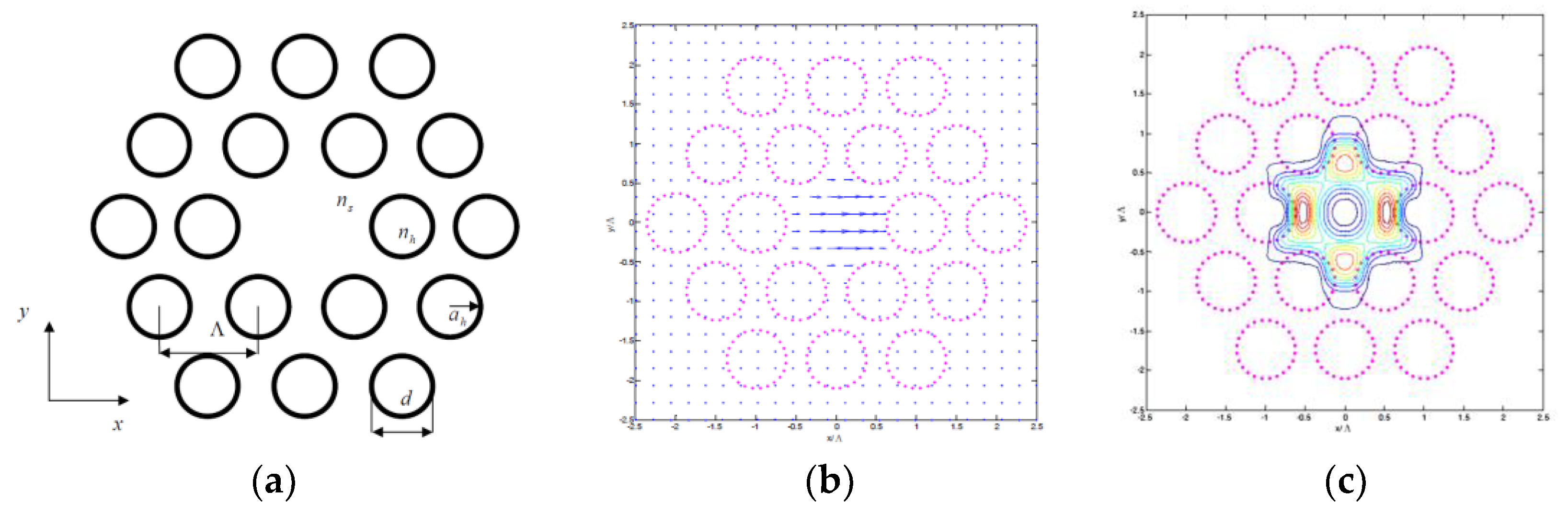
Figure 2.
Transverse magnetic-field vector distributions of the real part of (a) TE01, (b) HE21, and (c) TM01 modes (second-order mode) for the PCF. Field intensity distribution of the imaginary part of (d) TE01, (e) HE21, and (f) TM01 modes for the PCF with 2 air-hole rings (18 air-holes).
Figure 2.
Transverse magnetic-field vector distributions of the real part of (a) TE01, (b) HE21, and (c) TM01 modes (second-order mode) for the PCF. Field intensity distribution of the imaginary part of (d) TE01, (e) HE21, and (f) TM01 modes for the PCF with 2 air-hole rings (18 air-holes).
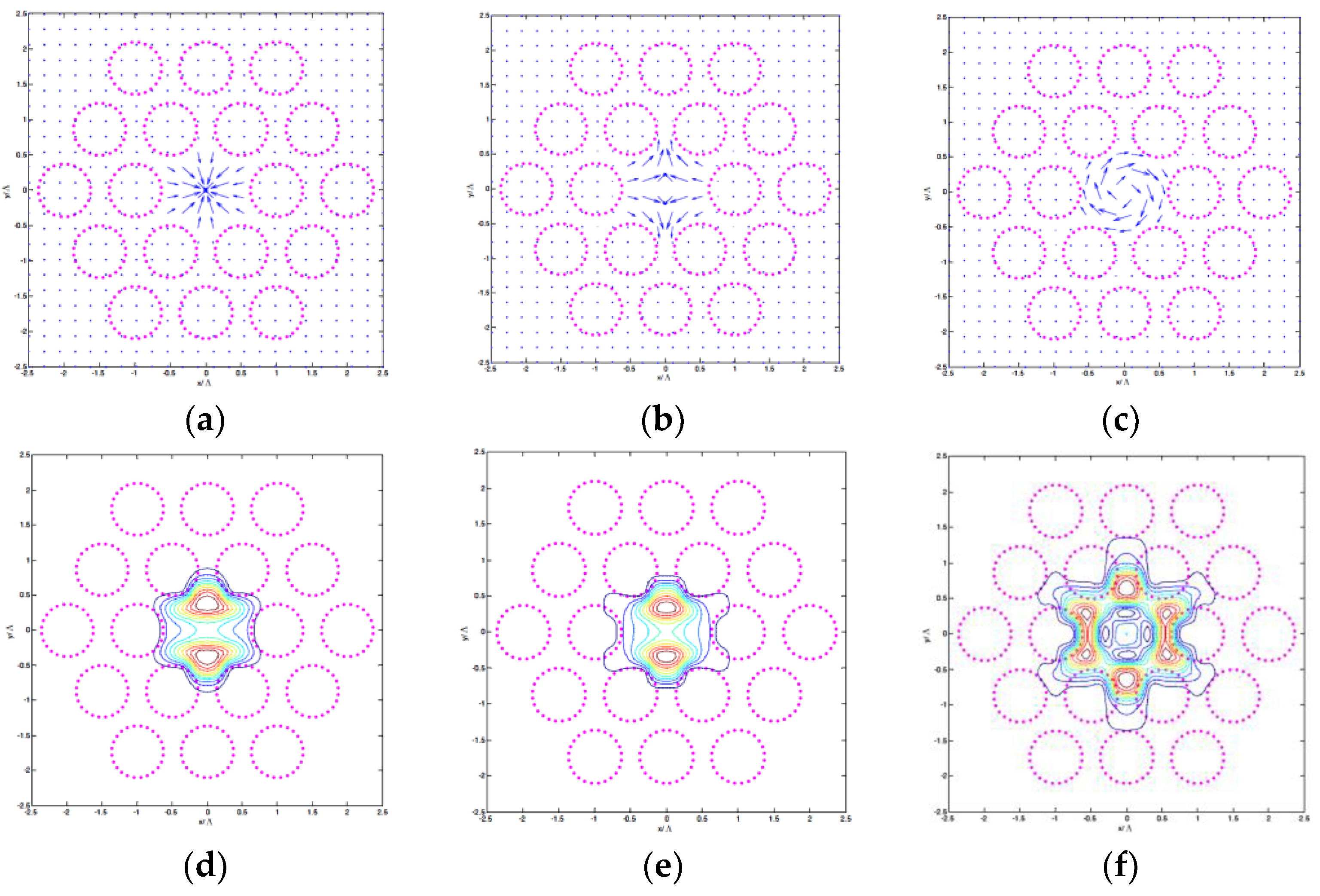
Figure 3.
Dependence of the relative error on the number of segments for the 2 air-hole ring (18 air-holes) configuration.
Figure 3.
Dependence of the relative error on the number of segments for the 2 air-hole ring (18 air-holes) configuration.

Figure 4.
Dispersion curves of the fundamental leaky mode for a PCF with two air-hole rings (18 air-holes), where Λ = 6.75 μm, d = 5 μm, and nsilica = 1.45.
Figure 4.
Dispersion curves of the fundamental leaky mode for a PCF with two air-hole rings (18 air-holes), where Λ = 6.75 μm, d = 5 μm, and nsilica = 1.45.

Figure 5.
(a) Schematic cross-section of the PCF with 4 air-hole rings (60 air-holes). The d/Λ is the air-hole size, and the background material is silica. (b) Intensity profile of the fundamental leaky mode for a PCF having 2 air-hole rings (18 air-holes), d/Λ = 0.4 and λ/Λ = 0.5.
Figure 5.
(a) Schematic cross-section of the PCF with 4 air-hole rings (60 air-holes). The d/Λ is the air-hole size, and the background material is silica. (b) Intensity profile of the fundamental leaky mode for a PCF having 2 air-hole rings (18 air-holes), d/Λ = 0.4 and λ/Λ = 0.5.
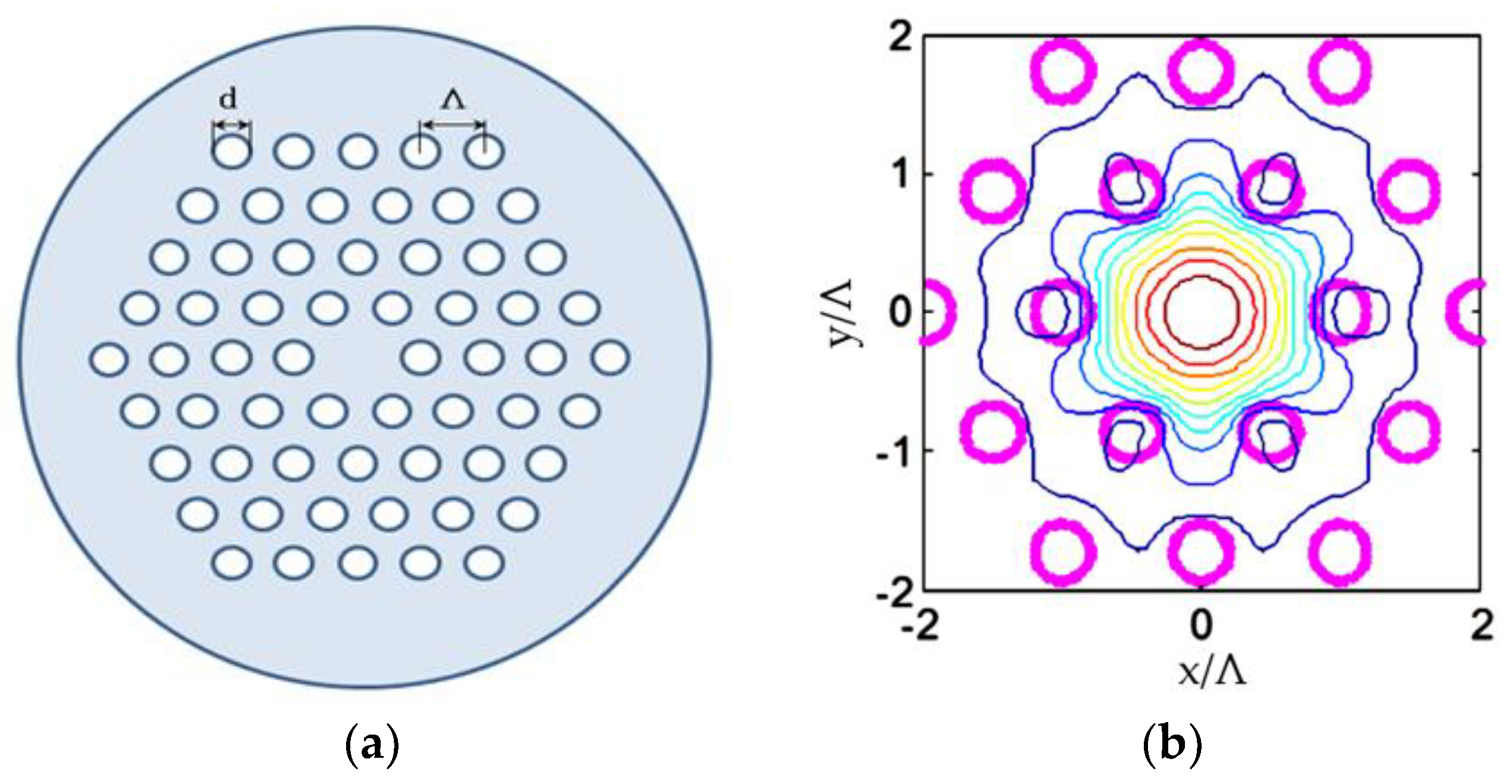
Figure 6.
Wavelength responses of the real part (solid line) and the imaginary part (dashed line) of neff for a 2 ring, 18 air-hole PCF when nsilica = 1.46 and d/Λ = 0.6.
Figure 6.
Wavelength responses of the real part (solid line) and the imaginary part (dashed line) of neff for a 2 ring, 18 air-hole PCF when nsilica = 1.46 and d/Λ = 0.6.
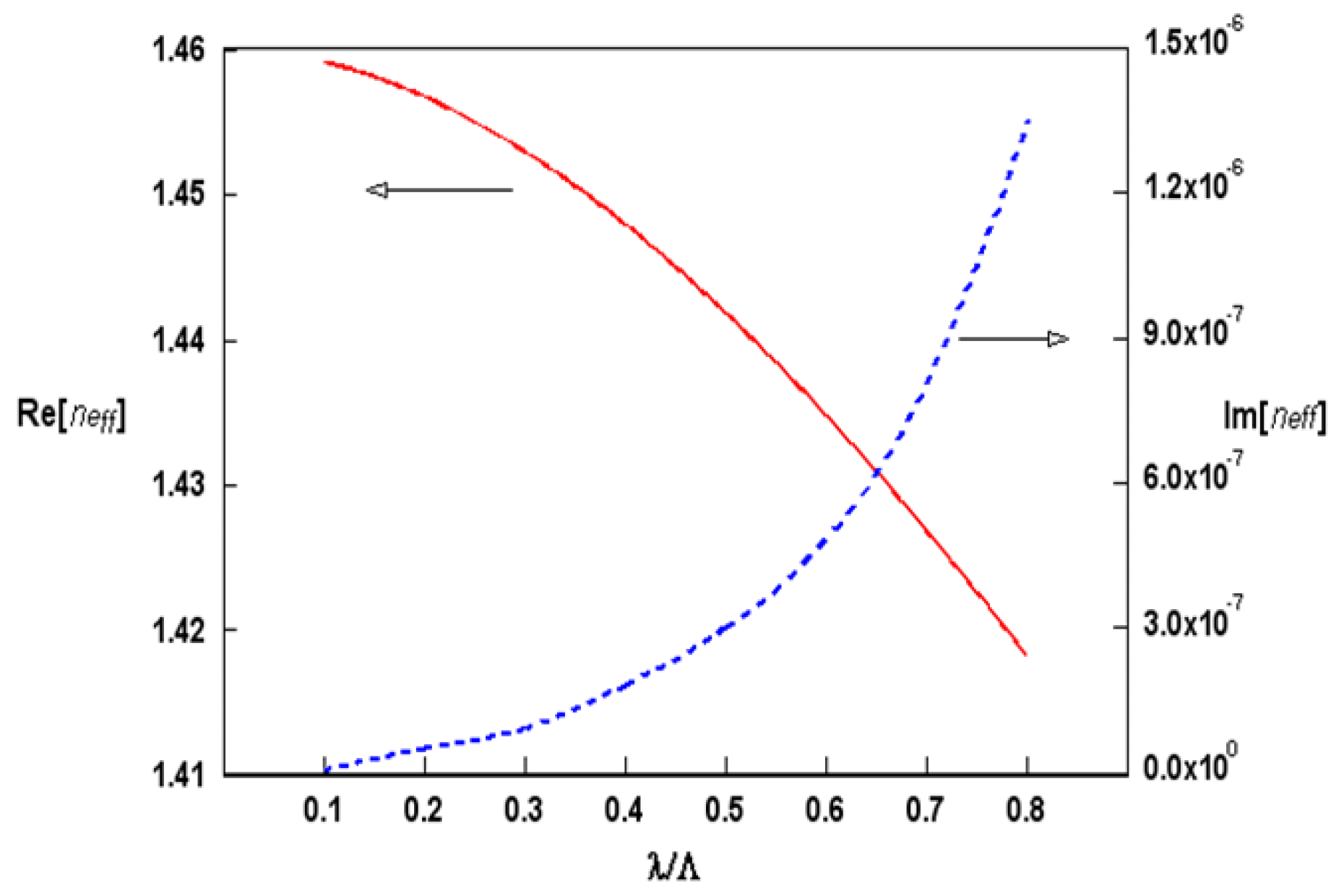
Figure 7.
Diagram of confinement losses versus the air-hole size d/Λ for various numbers of air-hole rings around the solid-core of a PCF.
Figure 7.
Diagram of confinement losses versus the air-hole size d/Λ for various numbers of air-hole rings around the solid-core of a PCF.

Figure 8.
Loss spectra of different air-hole sizes for a PCF having 3 rings (36 air-holes).


Table 1.
Comparison of mode class, complex effective index, and confinement loss for the algorithm based on the surface integral equation method (SIEM) and the multipole method [27] in Figure 1a.
| Mode Class | SIEM neff | Loss (dB/m) | Multipole Method neff |
|---|---|---|---|
| HE11 | 1.4453471152 + i2.684 × 10−8 | 1.01 | 1.4453471163 + i2.578 × 10−8 |
| TE01 | 1.4384402631 + i4.062 × 10−7 | 15.29 | 1.4384402675 + i4.101 × 10−7 |
| HE21 | 1.4383130349 + i6.974 × 10−7 | 26.25 | 1.4383130373 + i6.898 × 10−7 |
| TM01 | 1.4382295027 + i1.256 × 10−6 | 47.28 | 1.4382295029 + i1.268 × 10−6 |
© 2018 by the author. Licensee MDPI, Basel, Switzerland. This article is an open access article distributed under the terms and conditions of the Creative Commons Attribution (CC BY) license (http://creativecommons.org/licenses/by/4.0/).
Share and Cite
MDPI and ACS Style
Chiang, J.-S. Analysis of Leaky Modes in Photonic Crystal Fibers Using the Surface Integral Equation Method. Crystals 2018, 8, 177. https://doi.org/10.3390/cryst8040177
AMA Style
Chiang J-S. Analysis of Leaky Modes in Photonic Crystal Fibers Using the Surface Integral Equation Method. Crystals. 2018; 8(4):177. https://doi.org/10.3390/cryst8040177
Chicago/Turabian StyleChiang, Jung-Sheng. 2018. "Analysis of Leaky Modes in Photonic Crystal Fibers Using the Surface Integral Equation Method" Crystals 8, no. 4: 177. https://doi.org/10.3390/cryst8040177
Note that from the first issue of 2016, this journal uses article numbers instead of page numbers. See further details here.