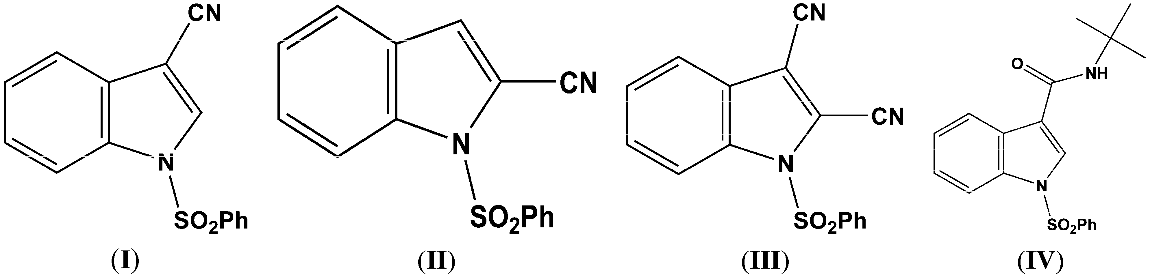
2.1. Structural Study of (I), (II), (III), and (IV)
The sulfonyl group in (
I), (
II), (
III), and (
IV) (
Figure 2,
Figure 3,
Figure 4 and
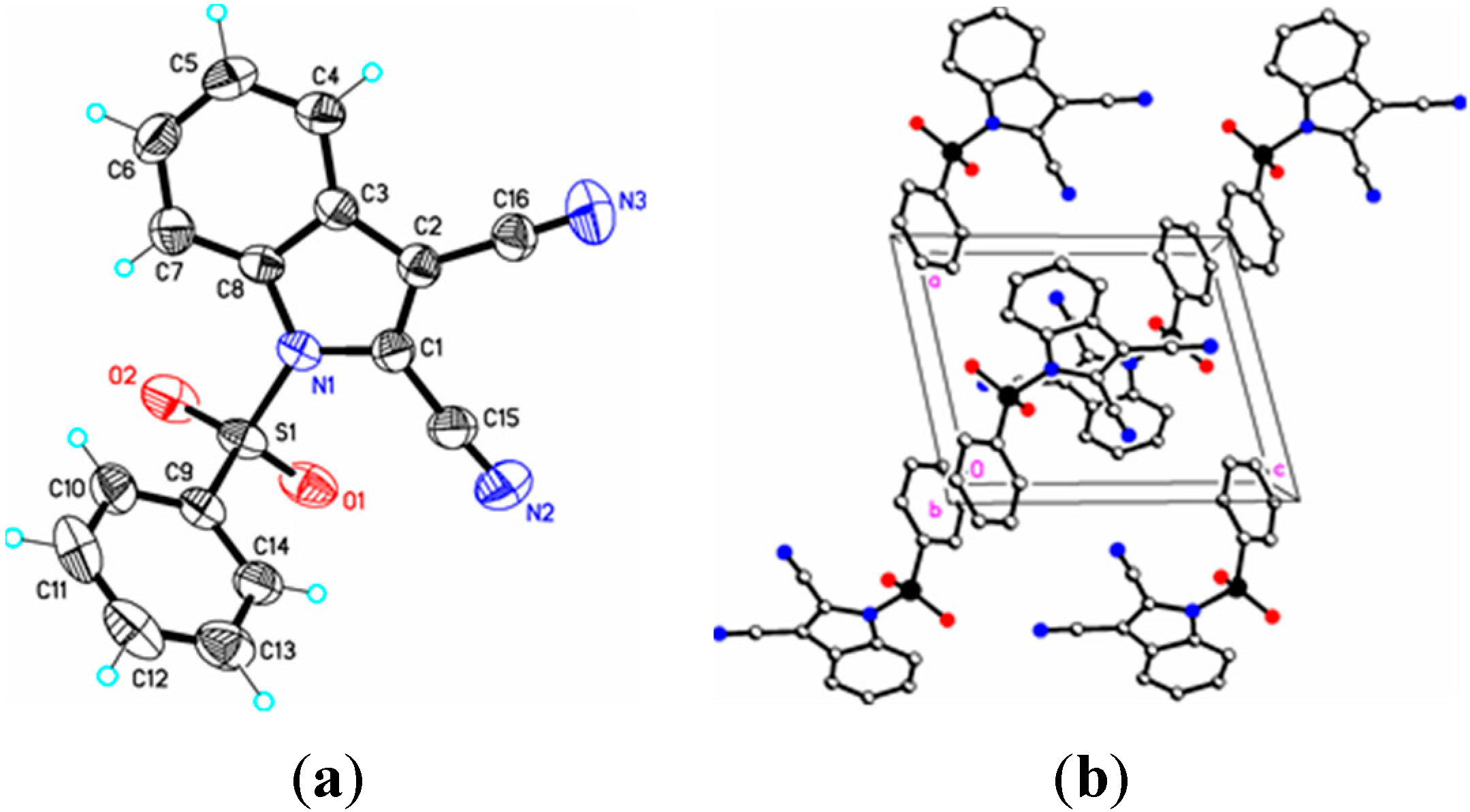
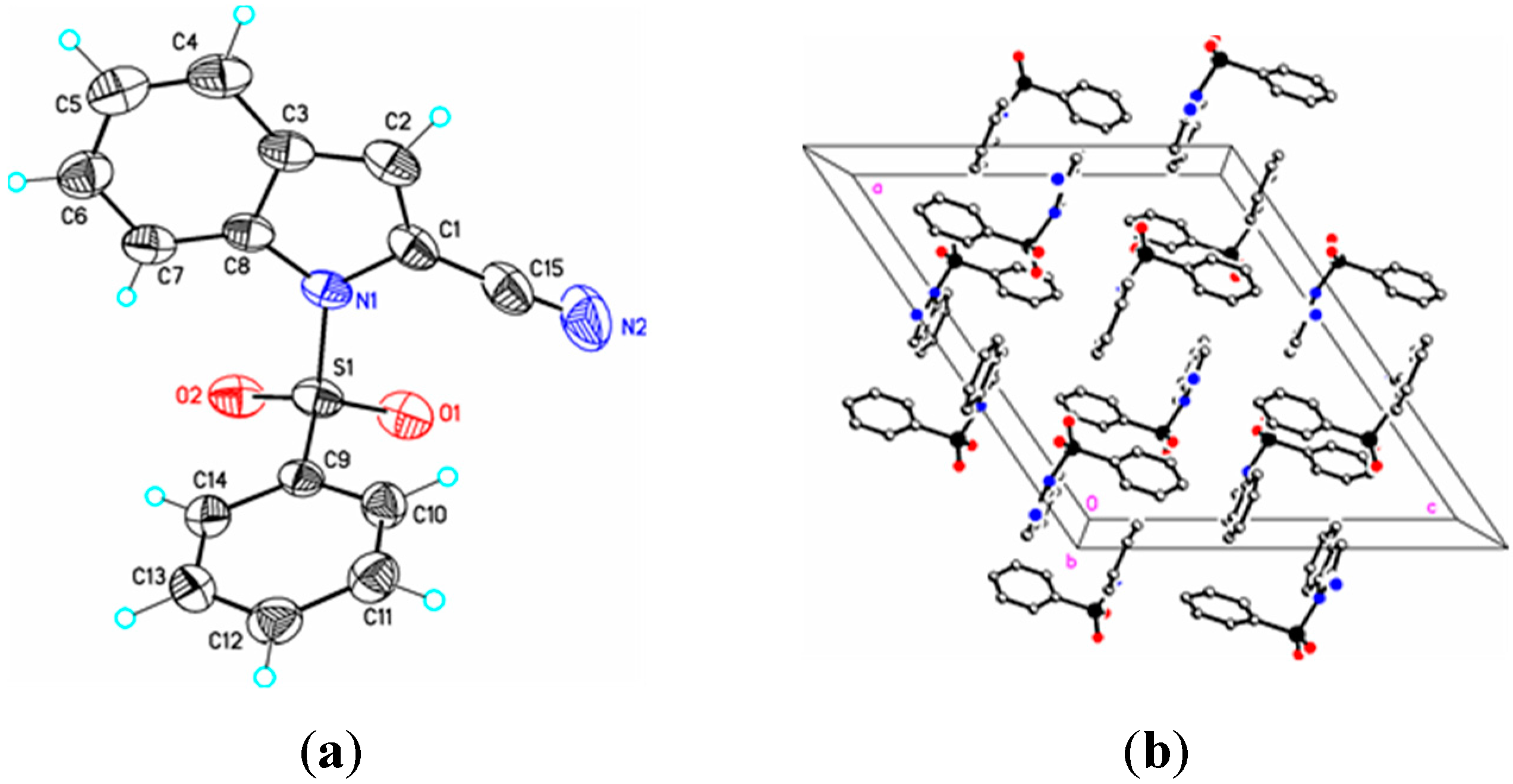
Figure 5) adopts the usual nitrogen-sulfonyl geometry seen in other 1-(phenylsulfonyl)indoles in which the nitrogen lone pair eclipses the two sulfur-oxygen bonds [
10,
11,
12].
Figure 2.
(a) ORTEP drawing of (I) showing the atom numbering scheme and 50% probability displacement ellipsoids of non-H atoms; (b) The molecular packing for (I) viewed along the b axis. Hydrogen atoms not involved in hydrogen bonding have been removed for clarity.
Figure 2.
(a) ORTEP drawing of (I) showing the atom numbering scheme and 50% probability displacement ellipsoids of non-H atoms; (b) The molecular packing for (I) viewed along the b axis. Hydrogen atoms not involved in hydrogen bonding have been removed for clarity.
Figure 3.
(a) ORTEP drawing of (II) showing the atom numbering scheme and 50% probability displacement ellipsoids of non-H atoms; (b) The molecular packing for (II) viewed along the b axis. Hydrogen atoms not involved in hydrogen bonding have been removed for clarity.
Figure 3.
(a) ORTEP drawing of (II) showing the atom numbering scheme and 50% probability displacement ellipsoids of non-H atoms; (b) The molecular packing for (II) viewed along the b axis. Hydrogen atoms not involved in hydrogen bonding have been removed for clarity.
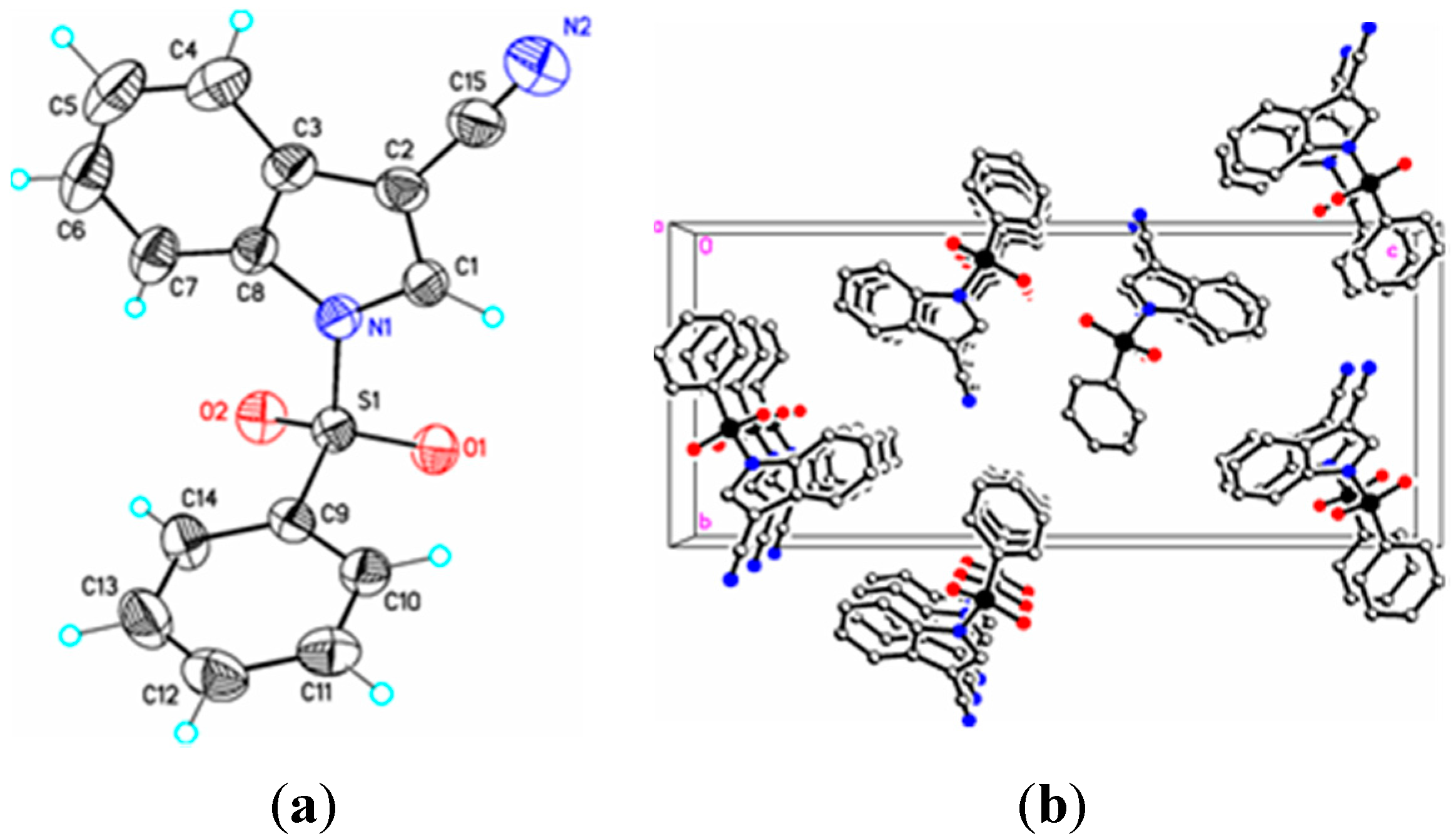
Figure 4.
(a) ORTEP drawing of (III) showing the atom numbering scheme and 50% probability displacement ellipsoids of non-H atoms; (b) The molecular packing for (III) viewed along the b axis. Hydrogen atoms not involved in hydrogen bonding have been removed for clarity.
Figure 4.
(a) ORTEP drawing of (III) showing the atom numbering scheme and 50% probability displacement ellipsoids of non-H atoms; (b) The molecular packing for (III) viewed along the b axis. Hydrogen atoms not involved in hydrogen bonding have been removed for clarity.
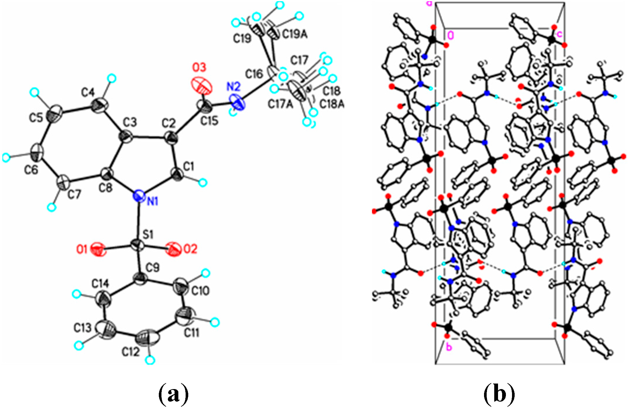
Figure 5.
(a) ORTEP drawing of (IV) showing the atom numbering scheme and 50% probability displacement ellipsoids of non-H atoms; (b) The molecular packing for (IV) viewed along the a axis. In (IVa) the tertiary butyl group is disordered over two sites in an occupancy ratio 0.544(10):0.456(10). Dashed lines in (IVb) indicate N2-H2N…O3 hydrogen bonding interactions. Hydrogen atoms not involved in hydrogen bonding have been removed for clarity.
Parameters are likewise in agreement with those described earlier for 1-(phenylsulfonyl)indoles. For example, the indole double bond length C1–C2 in (
I) (1.355(3) Å), (
II) (1.337(4) Å), (
III) (1.361(5) Å), and (
IV) (1.449(3) Å) are reasonably similar to that in 1-(phenylsulfonyl)indole (1.336(3) Å) [
12], but indicative of some influence by the C–3 cyano substituent in (
I) and (
III) (
Table 1). For these four compounds the sum of the angles around the indole nitrogen reveals the expected nearly ideal sp
2-hybridization: (
I), 358.8°; (
II), 357.4°; (
III), 359.9°; and (
IV), 357.5°. The indole rings are essentially planar in the four compounds and the dihedral angles between the mean planes of the indole and phenylsulfonyl rings are 85.4(2)°
(I), 87.2(7)° (
II), 75.1(7)° (
III), and 88.6(2)° (
IV), respectively. For comparison, this angle is 94.0(2)° in 1-(phenylsulfonyl)indole [
12].
Table 1.
Selected crystal and DFT bond lengths (Å), bond angles (°), and torsion angles (°) for (I) C15H10N2O2S, (II) C15H10N2O2S, (III) C16H9N3O2S and (IV) C19H20N2O3S.
Table 1.
Selected crystal and DFT bond lengths (Å), bond angles (°), and torsion angles (°) for (I) C15H10N2O2S, (II) C15H10N2O2S, (III) C16H9N3O2S and (IV) C19H20N2O3S.
| Atoms | Distance, Å | DFT, Å | | Atoms | Distance, Å | DFT, Å |
| (I) C15H10N2O2S |
| N1–S1 | 1.674(2) | *1.731 | | N1–C1 | 1.374(3) | *1.386 |
| N1–C8 | 1.409(3) | *1.410 | | N2–C15 | 1.131(4) | *1.165 |
| C15–C2 | 1.424(2) | *1.419 | | C1–C2 | 1.355(3) | *1.372 |
| S1–O1 | 1.4254(16) | *1.458 | | S1–O2 | 1.4170(18) | *1.458 |
| (II) C15H10N2O2S |
| S1–O2 | 1.4190(19) | *1.458 | | S1–O1 | 1.4200(19) | *1.455 |
| S1–N1 | 1.662(2) | *1.740 | | S1–C9 | 1.751(2) | *1.789 |
| N1–C8 | 1.407(3) | *1.405 | | N1–C1 | 1.412(3) | *1.414 |
| C1–C2 | 1.337(4) | *1.371 | | C1–C15 | 1.427(3) | *1.418 |
| C2–C3 | 1.414(4) | *1.428 | | N2–C15 | 1.150(4) | *1.164 |
| (III) C16H9N3O2S |
| S1–O2 | 1.414(3) | *1.457 | | S1–O1 | 1.413(3) | *1.454 |
| S1–N1 | 1.714(3) | *1.759 | | S1–C9 | 1.754(3) | *1.786 |
| N1–C1 | 1.388(4) | *1.400 | | N1–C8 | 1.406(4) | *1.405 |
| N2–C15 | 1.132(5) | *1.164 | | N3–C16 | 1.135(5) | *1.163 |
| C2–C16 | 1.436(5) | *1.419 | | C1–C15 | 1.428(5) | *1.417 |
| C1–C2 | 1.361(5) | *1.385 | | C2–C3 | 1.429(5) | *1.437 |
| (IV) C19H20N2O3S |
| S1–N1 | 1.6688(15) | *1.721 | | S1–C9 | 1.7551(19) | *1.792 |
| O3–C15 | 1.235(2) | *1.232 | | N1–C1 | 1.397(2) | *1.396 |
| N1–C8 | 1.413(2) | *1.410 | | N2–C15 | 1.337(2) | *1.370 |
| N2–C16 | 1.476(2) | *1.483 | | C1–C2 | 1.349(3) | *1.367 |
| C2–C3 | 1.449(3) | *1.450 | | C2–C15 | 1.483(2) | *1.487 |
| Atoms | Angles, ° | DFT, ° | | Atoms | Angles, ° | DFT, ° |
| (I) C15H10N2O2S |
| O2–S1–O1 | 121.64(10) | *123.10 | | O2–S1–N1 | 105.80(10) | *105.81 |
| O1–S1–N1 | 104.30(10) | *104.35 | | O1–S1–C9 | 109.32(10) | *108.82 |
| O2–S1–C9 | 109.63(10) | *108.98 | | N1–S1–C9 | 104.66(10) | *104.05 |
| C8–N1–S1 | 126.90(11) | *127.41 | | C2–C1–N1 | 109.08(19) | *109.29 |
| C1–N1–C8 | 108.98(19) | *109.19 | | C1–N1–S1 | 122.94(15) | *122.12 |
| (II) C15H10N2O2S |
| O2–S2–O1 | 121.13(12) | *122.53 | | O2–S2–N1 | 106.31(11) | *105.05 |
| O1–S1–N1 | 105.36(11) | *105.40 | | O2–S1–C9 | 109.10(11) | *109.06 |
| O1–S1–C9 | 108.75(11) | *109.12 | | N1–S1–C9 | 104.99(10) | *104.02 |
| C14–C9–S1 | 119.67(18) | *118.96 | | C8–N1–S1 | 125.13(16) | *126.99 |
| C1–N1–S1 | 125.38(19) | *124.26 | | C2–C1–N1 | 109.2(3) | *109.28 |
| C7–C8–N1 | 130.8(2) | *131.22 | | C2–C1–C15 | 126.8(3) | *126.15 |
| N2–C15–C1 | 174.5(3) | *175.57 | | C4–C3–C2 | 133.7(2) | *132.52 |
| N1–C1–C15 | 126.8(3) | *124.56 | | C1–C2–C3 | 109.0(2) | *107.89 |
| (III) C16H9N3O2S |
| O2–S–O1 | 122.22(18) | *123.96 | | O2–S1–N1 | 105.18(15) | *126.71 |
| O2–S1–N1 | 104.36(15) | *104.55 | | O2–S1–C9 | 109.80(17) | *109.46 |
| O1–S1–C9 | 109.43(17) | *109.55 | | N1–S1–C9 | 104.13(14) | *103.49 |
| N1–C1–C15 | 124.7(3) | *124.63 | | C8–N1–C1 | 108.7(3) | *108.56 |
| C3–C2–C16 | 126.01(3) | *126.15 | | C4–C3–C2 | 132.6(3) | *132.20 |
| C2–C1–N1 | 109.4(3) | *109.02 | | C1–C2–C16 | 126.0(3) | *126.33 |
| C8–N1–S1 | 126.3(2) | *127.08 | | C2–C1–C15 | 125.9(3) | *126.33 |
| C1–C2–C3 | 107.8(3) | *107.64 | | C1–N1–S1 | 124.9(2) | *124.03 |
| (IV) C19H20N2O3S |
| O2–S1–O1 | 121.46(9) | *122.66 | | O2–S1–N1 | 104.85(8) | *104.53 |
| O1–S1–N1 | 106.17(8) | *106.14 | | O2–S1–C9 | 109.02(9) | *108.62 |
| O1–S1–C9 | 108.96(9) | *108.80 | | N1–S1–C9 | 105.11(8) | *104.57 |
| C1–C2–C15 | 127.27(17) | *127.76 | | C3–C2–C15 | 124.84(17) | *125.11 |
| C2–C1–N1 | 109.91(16) | *109.87 | | C1–C2–C3 | 107.50(16) | *107.12 |
| C8-N1-S1 | 126.46(12) | *126.83 | | C15-N2-C16 | 124.62(17) | *125.42 |
| C1-N1-C8 | 108.16(15) | *108.57 | | C1-N1-S1 | 122.87(12) | *121.94 |
| Atoms | Torsions, ° | DFT, ° | | Atoms | Torsions, ° | DFT, ° |
| (I) C15H10N2O2S |
| O2–S1–N1–C1 | –158.34(18) | *–163.96 | | O1–S1–N1–C1 | –28.9(2) | *–28.96 |
| C9–S1–N1–C1 | 85.88(19) | *89.28 | | O2–S1–N1–C8 | 35.5(2) | *38.43 |
| O1–S1–N1–C8 | 164.89(19) | *169.60 | | C9–S1–N1–C8 | –80.3(2) | *–76.31 |
| N1–C1–C2–C15 | 179.6(2) | *178.54 | | C4–C3–C2–C15 | 0.7(4) | *0.34 |
| (II) C15H10N2O2S |
| O2–S1–N1–C8 | 38.8(2) | *20.81 | | O1–S1–N1–C8 | 168.47(18) | *151.45 |
| O2–S1–N1–C1 | –161.89(18) | *–171.16 | | C9–S1–N1–C8 | –76.8(2) | *–93.75 |
| O1–S1–N1–C1 | –32.2(2) | *–40.49 | | C9–S1–N1–C1 | 82.6(2) | *74.28 |
| S1–N1–C1–C2 | –165.63(19) | *–171.14 | | C8–N1–C1–C2 | –3.2(13) | *–1.17 |
| C8–N1–C1–C15 | 175.2(2) | *177.71 | | S1–N1–C1–C15 | 12.7(3) | *7.73 |
| C15–C1–C2–C3 | –176.3(2) | *–178.13 | | N1–C1–C2–C3 | 2.0(3) | *0.72 |
| (III) C16H9N3O2S |
| O1–S1–N1–C1 | –25.9(3) | *–40.02 | | C9–S1–N1–C1 | 88.8(3) | *74.91 |
| O2–S1–N1–C8 | 25.2(3) | *16.88 | | O1–S1–N1–C8 | 155.0(3) | *147.35 |
| C9–S1–N1–C8 | –90.3(3) | *–97.71 | | C8–N1–C1–C2 | –1.7(4) | *–0.54 |
| C15–C1–C3–C3 | –178.0(3) | *–177.96 | | C16–C2–C3–C4 | –1.6(6) | *–0.20 |
| N1–C1–C2–C16 | 179.8(3) | *179.59 | | C15–C1–C2–C16 | 0.7(6) | *2.14 |
| S1–N1–C1–C2 | 179.1(2) | *174.34 | | N1–C1–C2–C3 | 1.4(4) | *0.31 |
| (IV) C19H20N2O3S |
| O1–S1–N1–C1 | –155.47(15) | *–157.71 | | O2–S1–N1–C1 | –25.74(17) | *–26.76 |
| C9–S1–N1–C1 | 89.15(16) | *87.34 | | O2–S1–N1–C8 | 174.42(16) | *173.89 |
| C3–C2–C15–N2 | –154.56(19) | *–157.48 | | C3–C2–C15–O3 | 28.5(3) | *23.44 |
| O1–S1–N1–C8 | 44.69(18) | *42.94 | | C9–S1–N1–C8 | –70.69(17) | *–72.02 |
| C15–C2–C3–C8 | –173.38(18) | *–179.31 | | N1–C1–C2–C15 | 174.10(18) | *178.79 |
| CS–N1–C1–C2 | –164.64(14) | *–164.48 | | C8–N1–C1–C2 | –1.6(2) | *–1.80 |
In (
I) and (
II) the cyano triple bond lengths are 1.131(4) Å and 1.150(4) Å, respectively. The longer bond in (
II) may reflect electron donation from the indole nitrogen into the cyano π system. For comparison, 3-cyano-2-methyl-1-(4-methylphenyl)-5,6,7-trimethoxyindole has a C–N bond length of 1.142(2) Å [
14], 5-azido-3-cyano-1-methylindole has a CN bond length of 1.149(2) Å [
15], and 3-cyano-2,6-dimethyl-1-methoxyindole has a C–N bond length of 1.146(2) Å [
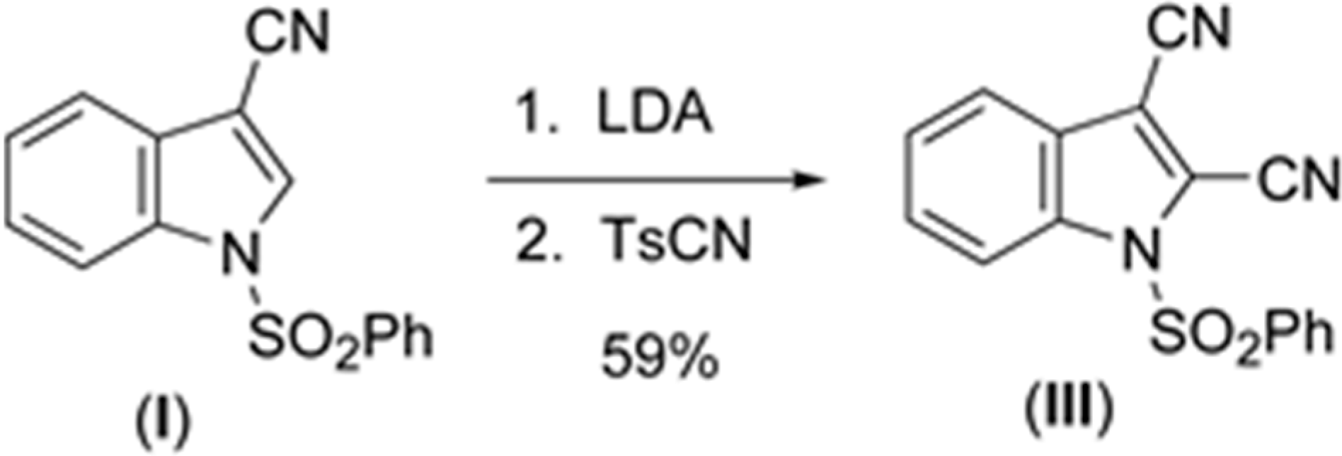
16]. Similar comparisons with known 2-cyanoindoles could not be found. In dicyanoindole (
III), the respective C–N bond lengths are identical, C–3 CN, 1.135(5) Å, and C–2 C–N, 1.132(5) Å. The C1–C2 indole double bond length in these three cyanoindoles is (
I), 1.355(3) Å; (
II), 1.337(4) Å; (
III), 1.361(5) Å, which may reflect some well-known π-donation into the C–3 cyano group from the indole double bond which would lengthen C1–C2. Any π donation into the C–2 cyano group is much less significant. Accordingly, N1–C1 in (
I) is shorter (1.374(3) Å) than N1–C1 in (
II) (1.412(3) Å). In (
III) this bond distance is 1.388(4) Å. The C15–C1–C2–C16 torsion angle is 0.7(6)°, the C15–C1–C2–C3 torsion angle is –178.0(3)°, and the N1–C1–C2–C16 torsion angle is 179.8(3)° indicating that the two cyano groups are coplanar and both lie in the plane of the indole ring. Likewise, in (
I) the N1–C1–C2–C15 and C4–C3–C2–C15 torsion angles are 179.6(2)° and 0.7(4) °, respectively. In (
II) the C3–C2–C1–C15 and S1–N1–C1–C15 torsion angles are –176.3(2)° and 12.7(3)°, respectively; the latter angle indicating that the N1–S1 bond is slightly out of the indole ring plane. In the crystal, weak C–H…O intermolecular interactions are observed in (
I), (
II), and (
III) (
Table 2). In addition, weak S–O…Cg (
I) and C–H…Cg (
II), (
III), (
IV) π-ring interactions and π–π stacking interactions in (
II) and (
III) are also present along with additional C–H…N interactions observed in (
III) (
Table 2). In (
II) the π–π stacking interactions are observed between nearby phenyl rings (Cg2–Cg3), whereas in (
III) these interactions exist on both the phenyl rings (Cg3–Cg3) as well as on the indole rings (Cg2–Cg1), forming a one-dimensional structure parallel to [111] and most likely as a result of the large difference in the indole-phenylsulfonyl dihedral angle observed between the actual and DFT calculated rings of 7.3(7)°. In (
II) this difference was observed as 3.0(8)°. The influence of the additional C–H…N interaction in (
III) appears to support this observation.
Table 2.
Hydrogen bond interactions for (I), (II), (III), and (IV) [Å and °].
Table 2.
Hydrogen bond interactions for (I), (II), (III), and (IV) [Å and °].
| D–H...A | d(D–H) | d(H...A) | d(D...A) | <(DHA) |
|---|
| (I) |
| C1–H1A...O1 #1 | 0.95 | 2.52 | 3.411(3) | 156 |
| S1–O2...Cg1 #2 | – | 3.09 | 3.8584(12) | 112 |
| S1–O4...Cg3 #2 | – | 3.22 | 3.9045(12) | 108 |
| (II) |
| C2–H2A…O2 #3 | 0.95 | 2.50 | 3.435(3) | 168 |
| C5A–H5A…Cg3 #4 | – | 2.85 | 3.721(4) | 152 |
| Cg2…Cg2 #4 | – | – | 3.753(2) | – |
| (III) |
| C5–H5A…N2 #5 | 0.95 | 2.61 | 3.540(5) | 172 |
| C13–H13A…O2 #6 | 0.95 | 2.52 | 3.257(5) | 134 |
| C4–H4A…Cg3 #7 | – | 2.61 | 3.499(4) | 156 |
| Cg2…Cg1 #7 | – | – | 3.797(2) | – |
| Cg3…Cg3 #8 | – | – | 3.809(2) | – |
| (IV) |
| N2–H2N…O3 #9 | 0.85 | 2.12 | 2.967(2) | 178 |
| C11–H11A…O2 #10 | 0.95 | 2.56 | 3.457(3) | 157 |
| C17–H17E…O3 | 0.98 | 2.17 | 2.867(8) | 127 |
| C6–H6A…O1 #11 | 0.95 | 2.59 | 3.540(3) | 176 |
| C5–H5A…Cg1 #12 | – | 2.93 | 3.794(3) | 152 |
| C18–H18C…Cg1 #13 | – | 2.75 | 3.702(8) | 163 |
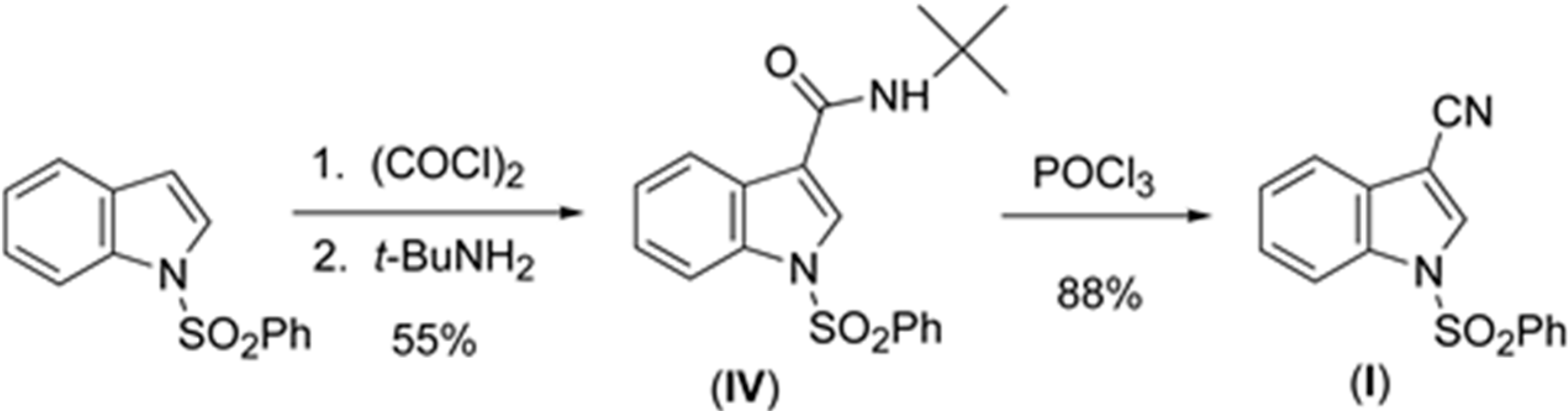
In (
IV), the methyl and ethyl atoms of the tertiary butyl group are disordered over two sites in an occupancy ratio 0.544(10): 0.456(10). In the crystal, N–H…O and C–H…O classical hydrogen bonds are observed forming chains along [001] (
Figure 4b,
Table 3). Weak C–H…O and C–H…Cg π-ring interactions are also observed (
Table 2) providing additional crystal stability. The amide functionality in (
IV) is in the expected anti-periplanar conformation and, as revealed by the torsion angles C3–C2–C15–N2, –154.56(19)° and C3–C2–C15–O3, 28.5(3)°, is twisted out of conjugation with the indole double bond. The somewhat large C15–N2–C16 bond angle, 124.64(17)°, perhaps results from steric repulsion between the carbonyl group (C15–O3) and the C16 tertiary butyl group. Overall, bond lengths and bond angles are all within expected ranges [
17], with small exceptions noted.
2.2. Theoretical Study of (I)
After a DFT geometry optimization calculation, the dihedral angle between the mean planes of the indole and phenylsulfonyl rings becomes 86.2(8)°, an increase of 0.8(6)°. Bond lengths and bond angles show only small changes with the exception of selected torsion angles consistent with the differences in the mean planes changes indicated above (
Table 1). These changes suggest that the single weak C–H…O intermolecular interaction involving the indole ring and a sulfonyl oxygen atom plays only a small role in the crystal packing of the molecule (
Table 2).
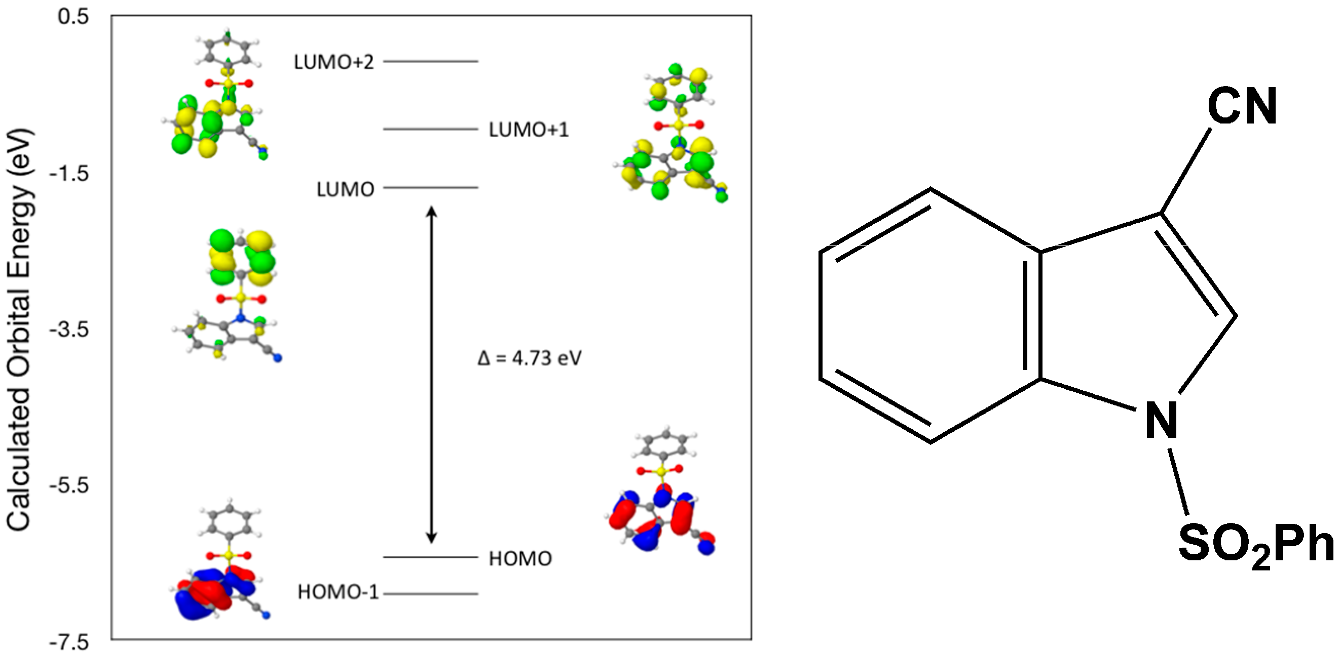
Calculated molecular orbital energies (eV) for the surfaces of the frontier molecular orbitals for (
I) show three absorption band envelopes, exhibiting some blue shifts, which are consistent with the experimental data (
Figure 6 and
Table 3) with λ
max values located at 292, 263, and 217 nm, respectively. The bands in the UV region 290–260 nm are assigned to cyano n → π* and π → π* transitions while the other band at 217 nm is assigned to aromatic π → π* transitions. In HOMO the electronic clouds are distributed primarily on the indole ring and cyano group. In HOMO–1 they are located only on the indole ring. In LUMO the electronic clouds are delocalized primarily on the phenyl ring while in LUMO+1 they are located on both the indole and phenyl rings, as well as on the cyano group. In LUMO+2 they are dispersed primarily on the indole ring. Therefore, the first absorption band envelope at 292 nm is assigned to contributions primarily from HOMO- > LUMO. The second absorption band at 263 nm is assigned to overlapping contributions from HOMO–1- > LUMO and HOMO- > LUMO+1. The third absorption band at 217 nm is assigned to overlapping contributions from HOMO–1- > LUMO+1, HOMO- > LUMO+2 and HOMO–1- > LUMO+2, respectively. It is evident that electron transitions among frontier molecular orbitals in (
I) are corrsponding to n → π*and π → π* transitions.
Figure 6.
Calculated frontier molecular orbitals for the C15H10N2O2S (I).
Figure 6.
Calculated frontier molecular orbitals for the C15H10N2O2S (I).
Table 3.
Experimental and calculated energy of molecular orbitals of (I) and associated transitions.
Table 3.
Experimental and calculated energy of molecular orbitals of (I) and associated transitions.
| Experimental | Calculated |
|---|
| λmax (nm/eV) | f | λmax (nm/eV) | MO Contributions |
| 292/4.25 | 0.07 | 262/4.73 | HOMO → LUMO |
| 263/4.71 | 0.13 | 238/5.20 | HOMO–1 → LUMO |
| 263/4.71 | 0.13 | 226/5.48 | HOMO → LUMO+1 |
| 217/5.71 | 0.25 | 208/5.95 | HOMO–1 → LUMO+1 |
| 217/5.71 | 0.25 | 195/6.35 | HOMO → LUMO+2 |
| 217/5.71 | 0.25 | 182/6.82 | HOMO–1 → LUMO+2 |
2.3. Theoretical Study of (II)
After a DFT geometry optimization calculation, the dihedral angle between the mean planes of the indole and phenylsulfonyl rings becomes 84.1(9)°, a decrease of 3.0(8)°. Again, bond lengths and bond angles show only small changes with the exception of selected torsion angles consistent with the differences in the mean planes changes indicated above (
Table 1). These changes also suggest that the single weak C–H…O intermolecular interaction involving the indole ring and a sulfonyl oxygen atom plays a small role in the crystal packing of the molecule (
Table 2).
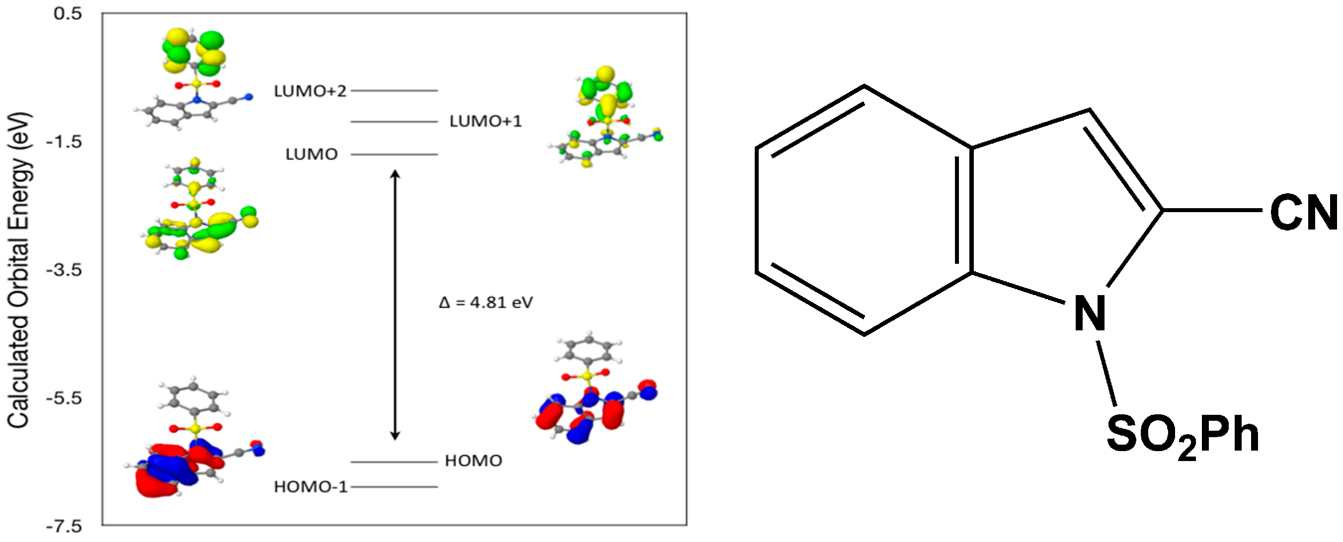
Calculated molecular orbital energies (eV) for the surfaces of the frontier molecular orbitals for (
II) show three absorption band envelopes, exhibiting some blue shifts, which are consistent with the experimental data (
Figure 7 and
Table 4) with λ
max values located at 310, 279 and 241 nm, respectively. The bands in the UV region 310–280 nm are assigned to cyano n → π* and π → π* transitions while the other band at 241 nm is assigned to aromatic π → π* transitions. In both HOMO and HOMO–1 the electronic clouds are distributed primarily on both the indole ring and cyano group. In LUMO the electronic clouds are delocalized primarily on the indole ring and cyano group while in LUMO+1 and LUMO+2 they are located only the phenyl ring. Electronic transitions are generally paired between the various molecular orbitals of the ground and excited states corresponding to these three band envelopes as indicated in
Table 4. Therefore, the first absorption band envelope at 310 nm is assigned to contributions primarily from HOMO- > LUMO. The second absorption band envelope at 279 nm is assigned to overlapping contributions from HOMO–1- > LUMO and HOMO- > LUMO+1. The third absorption band at 241 nm is assigned to overlapping contributions from HOMO–1- > LUMO+1, HOMO- > LUMO+2 and HOMO–1- > LUMO+2, respectively. It is evident that electron transitions among frontier molecular orbitals in (
II) are corrsponding to n → π*and π → π* transitions.
Figure 7.
Calculated frontier molecular orbitals for the C15H10N2O2S (II).
Figure 7.
Calculated frontier molecular orbitals for the C15H10N2O2S (II).
Table 4.
Experimental and calculated energy of molecular orbitals of (II) and associated transitions.
Table 4.
Experimental and calculated energy of molecular orbitals of (II) and associated transitions.
| Experimental | Calculated |
|---|
| λmax (nm/eV) | f | λmax (nm/eV) | MO Contributions |
| 310/4.00 | 0.02 | 258/4.81 | HOMO → LUMO |
| 279/4.44 | 0.09 | 238/5.20 | HOMO–1 → LUMO |
| 279/4.44 | 0.09 | 233/5.32 | HOMO → LUMO+1 |
| 241/5.14 | 0.01 | 217/5.71 | HOMO–1 → LUMO+1 |
| 241/5.14 | 0.01 | 214/5.81 | HOMO → LUMO+2 |
| 241/5.14 | 0.01 | 200/6.19 | HOMO–1 → LUMO+2 |
2.4. Theoretical Study of (III)
After a DFT geometry optimization calculation, the dihedral angle between the mean planes of the indole and phenylsulfonyl rings becomes 82.5(4) °, an increase of 7.3(7)°. Again, bond lengths and bond angles show only small changes with the exception of selected torsion angles consistent with the differences in the mean planes changes indicated above (
Table 1). These changes suggest that the two weak intermolecular interactions involving the indole ring (C–H…O) with a sulfonyl oxygen atom and with a cyano group (C–H…N) nitrogen atom play significant roles in the crystal packing of the molecule (
Table 2).
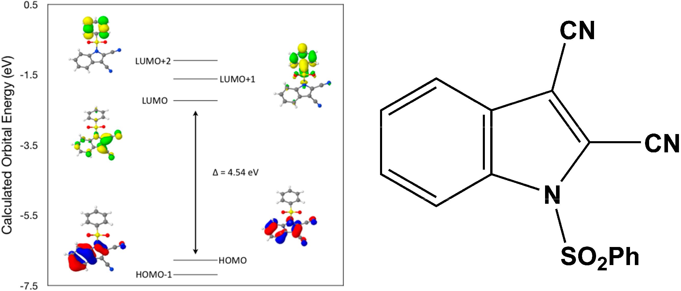
Calculated molecular orbital energies (eV) for the surfaces of the frontier molecular orbitals for (
III) show two absorption band envelopes, exhibiting some blue shifts, which are consistent with the experimental data (
Figure 8 and
Table 5) with λ
max values located at 298 and 229 nm, respectively. The band in the 300 nm UV region is assigned to cyano n → π* and π → π* transitions while the other band at 229 nm is assigned to aromatic π → π* transitions. In both HOMO and HOMO–1 the electronic clouds are distributed primarily on both the indole ring and cyano groups. In LUMO the electronic clouds are delocalized primarily on the indole ring and cyano group while in LUMO+1 and LUMO+2 they are located primarily on the phenyl ring. Electronic transitions are generally paired between the various molecular orbitals of the ground and excited states corresponding to these two band envelopes as indicated in
Table 5. Therefore, the first absorption band envelope at 298 nm is assigned to overlapping contributions primarily from HOMO- > LUMO, HOMO–1- > LUMO and HOMO- > LUMO+1. The second absorption band at 229 nm is assigned to overlapping contributions from HOMO–1- > LUMO+1, HOMO- > LUMO+2 and HOMO–1- > LUMO+2, respectively. Again, it is evident that electron transitions among frontier molecular orbitals in (
III) are corrsponding to n → π*and π → π* transitions.
Figure 8.
Calculated frontier molecular orbitals for the C16H9N3O2S (III).
Figure 8.
Calculated frontier molecular orbitals for the C16H9N3O2S (III).
Table 5.
Experimental and calculated energy of molecular orbitals of (III) and associated transitions.
Table 5.
Experimental and calculated energy of molecular orbitals of (III) and associated transitions.
| Experimental | Calculated |
|---|
| λmax (nm/eV) | f | λmax (nm/eV) | MO Contributions |
| 298/4.16 | 0.2 | 273/4.54 | HOMO → LUMO |
| 298/4.16 | 0.2 | 250/4.95 | HOMO–1 → LUMO |
| 298/4.16 | 0.2 | 241/5.15 | HOMO → LUMO+1 |
| 229/5.41 | 0.19 | 223/5.57 | HOMO–1 → LUMO+1 |
| 229/5.41 | 0.19 | 218/5.68 | HOMO → LUMO+2 |
| 229/5.41 | 0.19 | 203/6.09 | HOMO–1 → LUMO+2 |
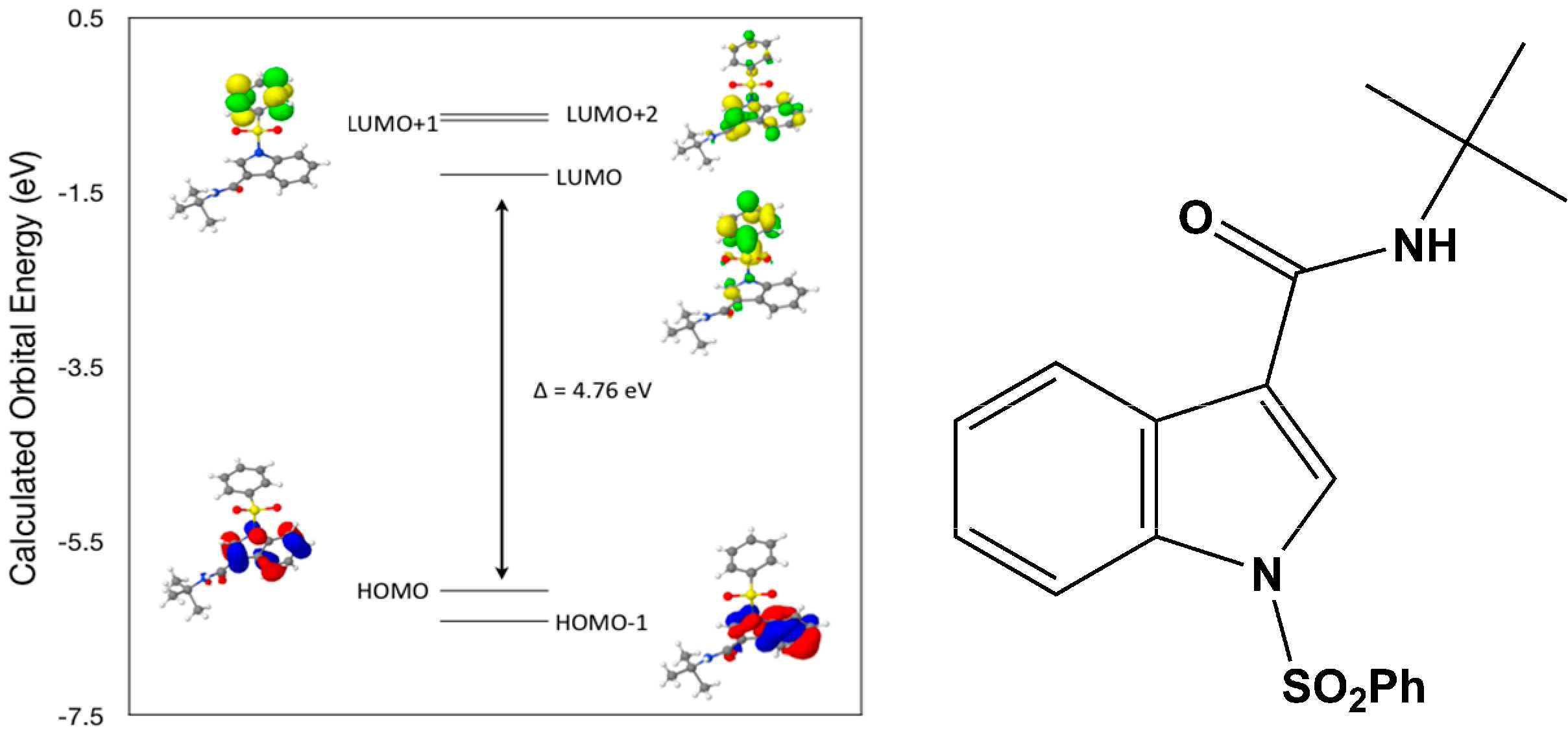
2.5. Theoretical Study of (IV)
After a DFT geometry optimization calculation, the dihedral angle between the mean planes of the indole and phenylsulfonyl rings becomes 89.5(3)°, an increase of 0.9(1)°. Again, bond lengths and bond angles show only small changes with the exception of selected torsion angles consistent with the differences in the mean planes changes indicated above (
Table 1). These changes suggest that the hydrogen bonds involving the carboxamide ligand (C–H…O and N–H…O) in concert with weak C–H…O intermolecular interactions involving the indole and phenyl groups with the two sulfonyl oxygen atoms play only a small role in the crystal packing of the molecule (
Table 2).
Calculated molecular orbital energies (eV) for the surfaces of the frontier molecular orbitals for (
IV) show two absorption band envelopes, exhibiting some blue shifts, which are consistent with the experimental data (
Figure 9 and
Table 6) with λ
max values located at 252 and 210 nm, respectively. Both bands in the 250 nm and 230 UV regions areassigned to aromatic π → π* transitions. In HOMO and HOMO–1 the electronic clouds are distributed primarily on the indole ring. In LUMO and LUMO+1 the electronic clouds are delocalized primarily on the phenyl ring while in LUMO+2 they are located only on the indole ring. Electronic transitions are generally paired between the various molecular orbitals of the ground and excited states corresponding to these two band envelopes as indicated in
Table 6. Therefore, the first absorption band envelope at 252 nm is assigned to contributions primarily from HOMO- > LUMO and HOMO–1- > LUMO. The second absorption band at 210 nm is assigned to overlapping contributions from HOMO- > LUMO+1, HOMO- > LUMO+2, HOMO–1- > LUMO+1 and HOMO–1- > LUMO+2, respectively. Again, it is evident that electron transitions among frontier molecular orbitals in (
IV) are corrsponding to n → π*and π → π* transitions.
Figure 9.
Calculated frontier molecular orbitals for the C19H20N2O3S (IV).
Figure 9.
Calculated frontier molecular orbitals for the C19H20N2O3S (IV).
Table 6.
Experimental and calculated energy of molecular orbitals of (IV) and associated transitions.
Table 6.
Experimental and calculated energy of molecular orbitals of (IV) and associated transitions.
| Experimental | Calculated |
|---|
| λmax (nm/eV) | f | λmax (nm/eV) | MO Contributions |
| 252/4.92 | 0.24 | 260/4.76 | HOMO → LUMO |
| 252/4.92 | 0.24 | 242/5.11 | HOMO–1 → LUMO |
| 210/5.90 | 0.3 | 230/5.39 | HOMO → LUMO+1 |
| 210/5.90 | 0.3 | 227/5.45 | HOMO → LUMO+2 |
| 210/5.90 | 0.3 | 216/5.74 | HOMO–1 → LUMO+1 |
| 210/5.90 | 0.3 | 214/5.80 | HOMO–1 → LUMO+2 |


