High-Performing PGM-Free AEMFC Cathodes from Carbon-Supported Cobalt Ferrite Nanoparticles
by
 , , ,
, , ,
Xiong Peng
1,† ,
,
Varchaswal Kashyap
2,3,†,
Benjamin Ng
1,
Sreekumar Kurungot
2,3,
Lianqin Wang
4,
John R. Varcoe
4 and
William E. Mustain
1,*
1
Department of Chemical Engineering, University of South Carolina, Columbia, SC 29208, USA
2
Physical and Materials Chemistry Division, CSIR-National Chemical Laboratory, Dr. Homi Bhabha Road, Pune 41108, India
3
Academy of Scientific and Innovative Research, Anusandhan Bhawan, 2 Rafi Marg, New Delhi 110001, India
4
Department of Chemistry, University of Surrey, Guildford GU2 7XH, UK
*
Author to whom correspondence should be addressed.
†
These authors contributed equally to this work.
Catalysts 2019, 9(3), 264; https://doi.org/10.3390/catal9030264
Submission received: 21 January 2019
/
Revised: 3 March 2019
/
Accepted: 12 March 2019
/
Published: 15 March 2019
(This article belongs to the Special Issue Catalysts for Polymer Membrane Fuel Cells)
Abstract
:Efficient and durable non-precious metal electrocatalysts for the oxygen reduction reaction (ORR) are highly desirable for several electrochemical devices, including anion exchange membrane fuel cells (AEMFCs). Here, cobalt ferrite (CF) nanoparticles supported on Vulcan XC-72 carbon (CF-VC) were created through a facile, scalable solvothermal method. The nano-sized CF particles were spherical with a narrow particle size distribution. The CF-VC catalyst showed good ORR activity, possessing a half-wave potential of 0.71 V. Although the intrinsic activity of the CF-VC catalyst was not as high as some other platinum group metal (PGM)-free catalysts in the literature, where this catalyst really shined was in operating AEMFCs. When used as the cathode in a single cell 5 cm−2 AEMFC, the CF-VC containing electrode was able to achieve a peak power density of 1350 mW cm−2 (iR-corrected: 1660 mW cm−2) and a mass transport limited current density of more than 4 A cm−2 operating on H2/O2. Operating on H2/Air (CO2-free), the same cathode was able to achieve a peak power density of 670 mW cm−2 (iR-corrected: 730 mW cm−2) and a mass transport limited current density of more than 2 A cm−2. These peak power and achievable current densities are among the highest reported values in the literature to date.
1. Introduction
To enable a shift away from fossil fuels to clean-energy alternatives with reduced environmental impact, it is important to search for safe, efficient and economical energy conversion technologies that can be commercialized. Fuel cells are electrochemical devices that directly convert stored chemical energy into electricity with high efficiency. They have received a significant amount of attention for many applications, including transportation, where the proton exchange membrane fuel cell (PEMFC) has dominated the market. However, the broad commercialization of PEMFCs has been hindered by high cost, which is partially caused by the use of platinum group metal (PGM) catalysts at both the anode and cathode [1]. In recent years, anion exchange membrane fuel cells (AEMFCs) have been proposed as a potentially lower-cost alternative to PEMFCs. It is believed that the alkaline electrolyte would make it possible to use non-PGM electrocatalysts from a broader selection of materials that are unstable in acid as well as enable lower cost hardware and membranes. This combination of non-PGM catalysts with potentially low-cost membranes and other cell components may allow AEMFCs to be much lower cost than PEMFCs at scale.
Although discovering non-PGM catalysts for both fuel cell reactions is important, a majority of the work to date has focused on the oxygen reduction reaction (ORR), which is the cathode reaction not only for AEMFCs, but other technologies as well, such as metal air batteries. This suggests that advancements made at the AEMFC cathode could have a wide-reaching impact on a number of electrochemical technologies [2]. Researchers have developed non-PGM ORR catalysts with a wide array of chemistries and structures [3,4,5]. Several groups have reported Fe- and Co-doped catalysts derived from the high temperature annealing of a polymeric precursor [6,7], resulting in highly porous or hierarchical structures, but with many active sites buried within the bulk material or pores that are unreachable by the ionomer. Such catalysts have often shown very high ex-situ ORR activity [6,7], but one limitation of these materials has been how they are implemented into electrodes. Hence, a majority of non-PGM electrocatalysts have not been successfully transitioned to operating AEMFCs due to the inability of researchers to create properly structured electrodes with sufficient mass transport, porosity, electronic conductivity and catalyst layer (CL) thickness [8], with a few notable exceptions [8,9,10]. Another potential issue with these materials has been their low durability, and their likely high production cost is also potentially problematic.
Another class of catalysts that has been explored is carbon-supported metal oxide nanoparticles [11]. Recently, success has been reported using cobalt and manganese oxides grown on a N-doped graphene support [12], creating covalent coupling between spinel oxide nanoparticles and N-doped graphene oxide sheets, which yielded higher alkaline ORR activity than commercial Pt/C. However, one of the limitations of the graphene approach is that graphene layers are prone to stacking during electrode fabrication. Hence, an expensive, hard-to-scale freeze-drying step was needed to form a 3D porous electrode [12]. A recently successful approach that showed very high catalyst activity, AEMFC performance and durability was to create platelet-structured catalysts where the N-doped carbon was grown between templated metal oxide particles [9]. Not only did the N-C-CoOx catalyst in that study show excellent intrinsic activity, the electrode-level mass transport was also enhanced by integrating a powder-based ionomer during electrode fabrication, which was a previously successful approach with another non-PGM cathode [10]. Although the creation of the N-C-CoOx catalyst did not require any exotic reagents, like nearly all other high-activity non-PGM catalysts it does require high-temperature processing that may be undesirable in some manufacturing environments.
In this study, we have created a highly active non-PGM catalyst at very low temperature through the solvothermal synthesis of cobalt ferrite nanoparticles supported by Vulcan carbon (CF-VC), which is an easily scalable approach. CF particles were targeted because it is believed that their magnetic nature would facilitate the magneto hydrodynamic movement of the reactants, resulting in high ORR activity [13]. Vulcan carbon was chosen as the catalyst support as it provides a unique combination of high surface area, high electrical conductivity and mesoporous structure, which can be beneficial for reducing electron transfer and mass transport resistances when integrated into fuel cell catalyst layers. The CF-VC catalyst was first characterized through a combination of imaging and X-ray diffraction (XRD). The catalyst was then deposited onto a rotating disk electrode (RDE) where its activity was probed ex-situ. Next, the catalyst was integrated with a powder ionomer [14] to create gas-diffusion electrodes and tested for its ORR performance in operating AEMFCs.
2. Results and Discussion
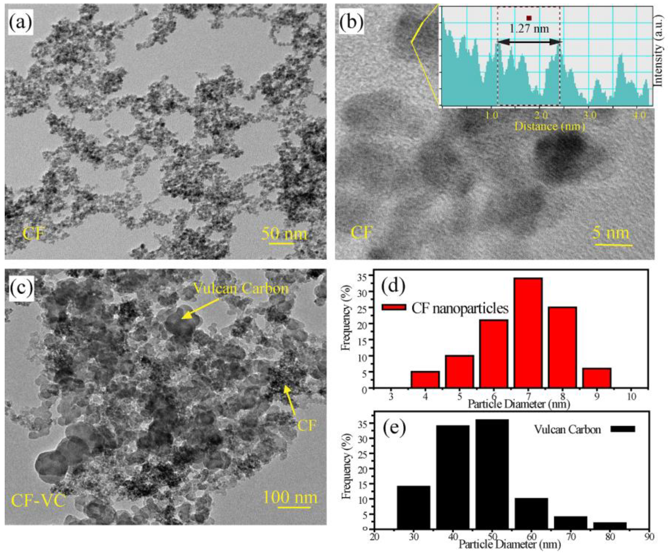
The morphology, structure and size distribution of the CF nanoparticles were analyzed by transmission electron microscopy (TEM) and the resulting images are presented in Figure 1. The ferrite nanoparticles were spherical in structure and well distributed. Because they are magnetic in nature, they are generally restricted to individual particles. Hence, despite their close association, very little agglomeration was observed. A magnified image of the nanoparticles is presented in Figure 1b and a corresponding line profile analysis is shown in the inset. Careful analysis of the CF particles showed a d-spacing of 0.254 nm, corresponding to the (311) plane of the cobalt ferrite (0.252 nm) [15]. The small variation in the d-spacing can be explained by the presence of oxygen vacancies and crystal relaxation due to the nanoparticle nature of the CF.
In order to create the final catalyst, the CF nanoparticles were physically mixed with Vulcan XC-72R carbon (50:50 wt%) and annealed at 150 °C for 12 h. Transmission electron microscopy (TEM) analysis of the final CF-VC catalyst clearly showed the distribution of the CF nanoparticles and the Vulcan carbon (Figure 1c). The particle size distribution of the CF and Vulcan carbon were determined through analysis of multiple images (Figure S1 in the supporting information) using the Digital Micrograph software, which are presented in Figure 1d,e. The CF nanoparticles and Vulcan carbon had a primary size distribution of 6–8 nm and 40–50 nm, respectively. The annealing of the cobalt ferrite nanoparticles with Vulcan carbon provides an electrically conducting network, which allows for the active material to be better utilized and the apparent ORR activity to be improved. Also, the spherical shape of the Vulcan carbon does not allow for the extensive catalyst stacking and densification that can occur with graphene-based catalysts.
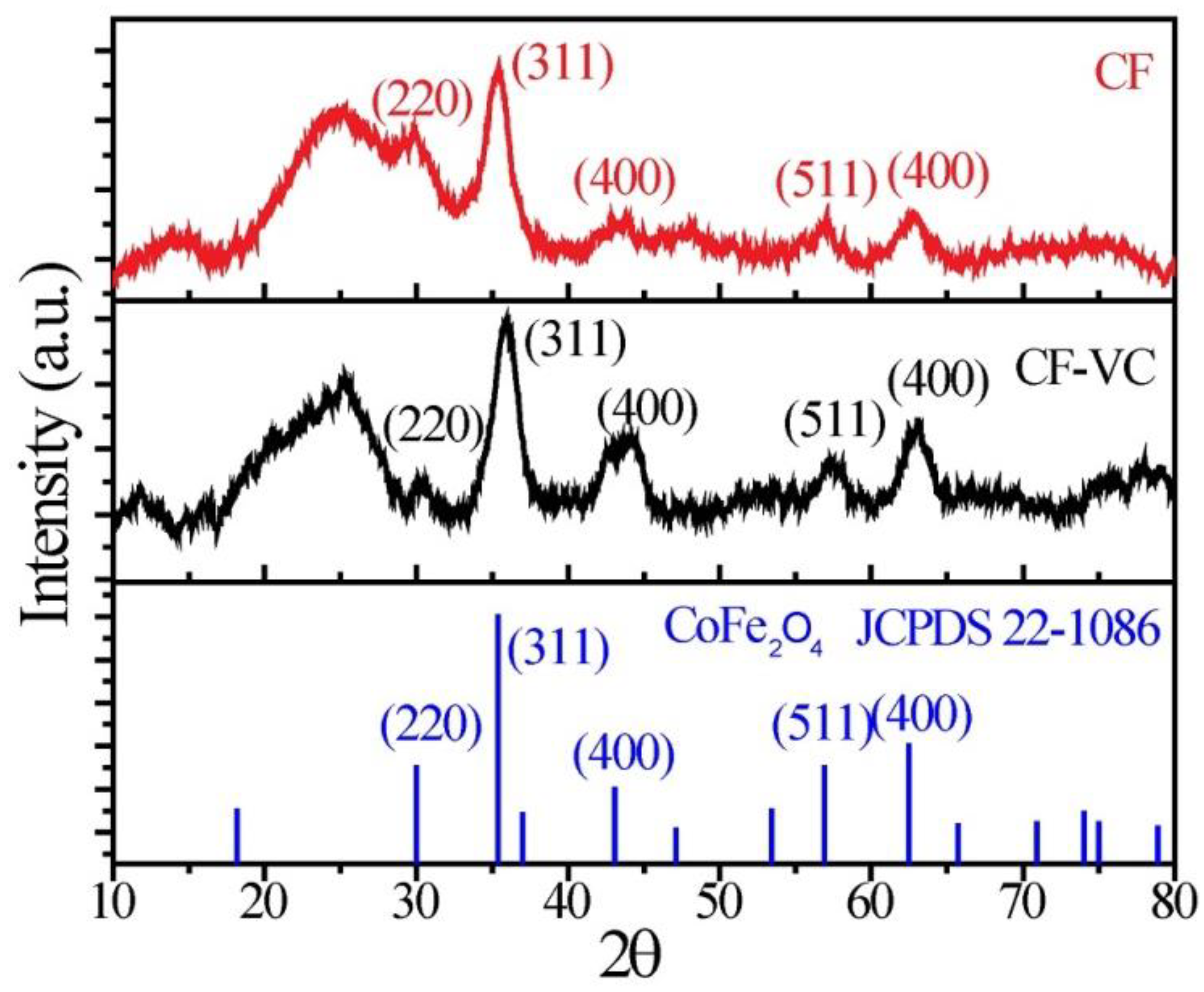
Powder X-ray diffraction (XRD) patterns for raw CF and CF-VC are presented in Figure 2. Being nanocrystalline, as observed in the TEM images, the XRD peaks were generally broad, although the characteristic peak for spinel cobalt ferrite (JCPDS 22-1086) at 35.3 2θ for the (311) plane was well resolved. Peaks corresponding to the (400), (511) and (440) reflections were also clearly observed at 43.8, 57.2 and 62.8 2θ, respectively. Comparing the XRD pattern of the raw CF and the CF-VC, the intensity of each of the individual peaks was increased in the CF-VC catalyst, most likely due to the additional heat treatment, which increased the CF crystallinity.
Information regarding the catalyst surface was obtained using X-ray photoelectron spectroscopy (XPS), with a summary of the results presented in Figure 3. Broad survey spectra for both CF and CF-VC, Figure 3a, revealed peaks corresponding to C 1s, O 1s, Fe 2p and Co 2p at 282.7, 531, 711.2 and 785 eV, respectively [16]. From the survey spectra, it was clear that the O 1s intensity was higher for CF and the C 1s intensity was higher for the CF-VC catalyst. Significant changes were observed to the oxygen-binding environment for the CF by annealing with Vulcan carbon, which can be shown in the high resolution O1s spectra (Figure 3b). In the deconvolution, OL represents the lattice oxygen, OV denotes oxygen vacancies and OMC signifies metal carbonates (formed during the solvothermal process) [17]. It appears that the annealing of the CF nanoparticles decomposed the metal carbonates and, consequently, the relative OMC intensity was decreased in the CF-VC compared to CF. The deconvoluted Co 2p and Fe 2p spectra are presented in Figure 3c and Figure 3d, respectively. The peaks corresponding to the Co and Fe atoms were less intense in the CF-VC catalyst, as half of the catalyst mass was Vulcan carbon. The binding energy for Co3+ and Co2+ in CF were observed at 780.2 and 782.3 eV [18]. In the CF-VC catalyst, Co3+ and Co2+ appeared at very similar binding energies, 780.2 and 781.8 eV, respectively. The annealing of CF with Vulcan carbon changed the Co3+/Co2+ratio, which is clearly shown in the area occupied by the two states in the deconvoluted spectra (Figure 3c). This change in the oxidation state was not limited to cobalt; a significant change in the iron oxidation state was also observed. Peaks for Fe2+ and Fe3+ were observed at 709.7 and 710.8 eV in the CF nanocrystals. However, in the CF-VC, the peak positions were slightly shifted to 709.8 and 711.2 eV. The peak areas and peak widths for each of the metal oxidation states are given in Table S1. Moreover, the change in the oxidation state of the cobalt and iron—from the XPS peak intensity and area—show structural changes in the nanocrystals. The Fe+3/Fe+2 ratio also changed from CF to CF-VC, also as a result of annealing. The change in oxidation states after annealing makes perfect sense. Because the annealing decomposed the surface carbonates, oxygen vacancies were formed that—because of the need for crystal neutrality—led to the change in the oxidation state of the metal atoms.
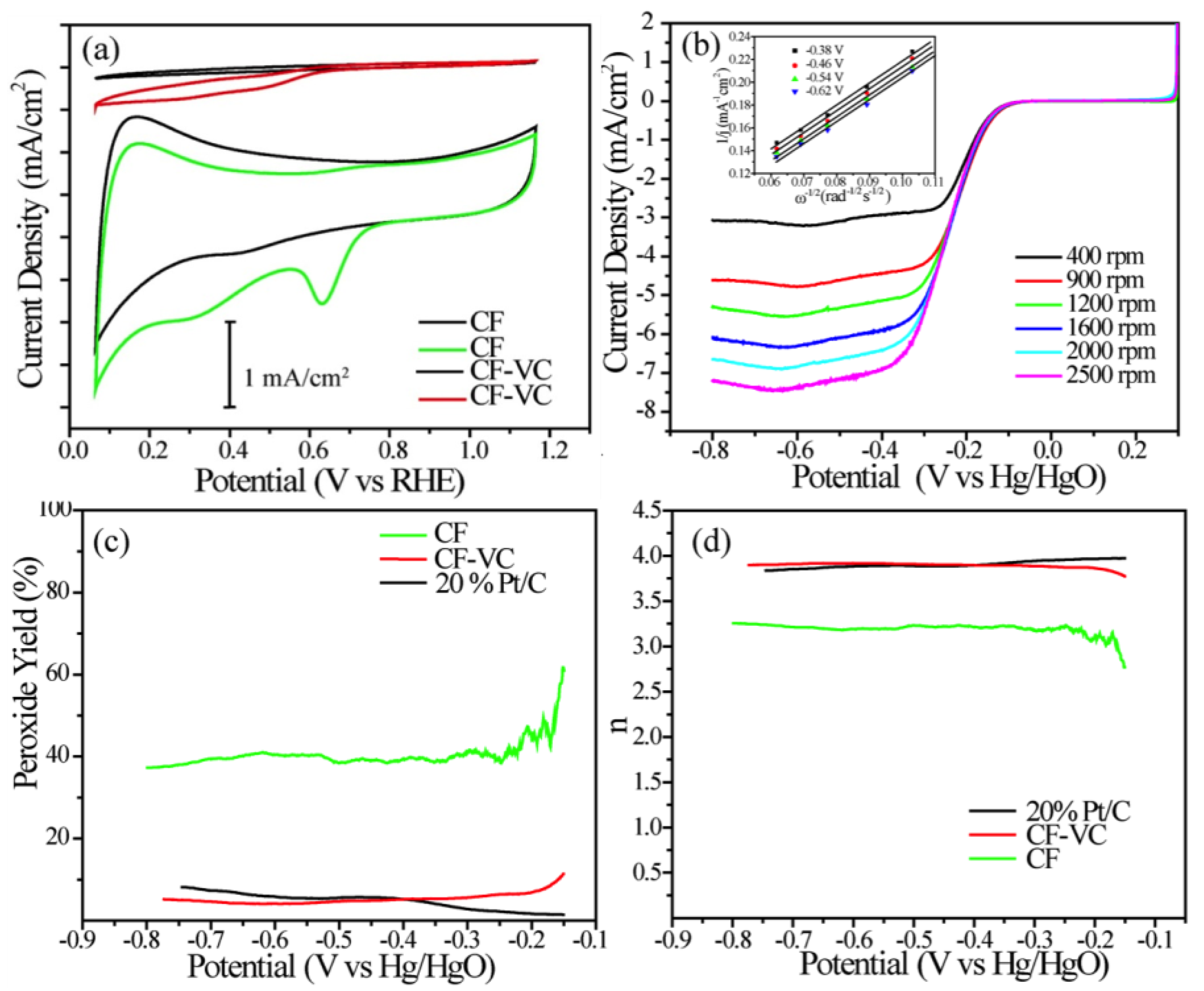
The intrinsic activity of the catalysts towards the oxygen reduction reaction was investigated electrochemically using a combination of cyclic voltammetry (CV) and linear sweep voltammetry (LSV) on RDEs and rotating ring disk electrodes (RRDEs). The electrolyte used in this work was 0.1 M KOH, and the experiments were done in nitrogen- and oxygen-saturated environments sequentially (Figure 4). The CVs for CF and CF-VC clearly showed two characteristic processes at high potentials: pseudocapacitance from the high surface area carbon and oxygen reduction. The CF catalyst showed very little overall activity for the oxygen reduction reaction, which is evidenced by both the low current densities in the CVs (Figure 4a) and the high peroxide yield (Figure 4c). On the other hand, the CF-VC catalyst showed a significantly improved voltammetric response. First, the electrode capacitance was greatly enhanced due to the presence of the Vulcan carbon. Second, a clear ORR peak emerged at 0.62 V (vs. the reversible hydrogen electrode, RHE), which is likely enabled by both higher electronic conductivity (increasing catalyst utilization) and surface modification from the annealing step.
Because of the enhanced voltammetric response and a clear ORR peak, the behavior of the CF-VC catalyst was also probed by LSV under rotation, and the results are shown in Figure 4b. Electrode rotation is an important part of the ex situ kinetic evaluation of ORR catalysts because it enables homogenous oxygen accessibility over the catalyst surface, removing any uncertainties in the experimental data related to mass transport, allowing pure kinetic information to be extracted from the RDE and RRDE data. The first kinetic parameters that were extracted were the onset and half-wave potentials—0.78 and 0.71 V, respectively. It should be noted that these values are ca. 100 mV negative of current state-of-the-art PGM-free ORR catalysts [19,20,21,22], although they are still very good relative to most PGM-free catalysts reported in the literature. RDE data was collected at multiple rotation rates and a Kouteckey–Levich (K–L) analysis was performed to probe the reaction mechanism. A K–L plot, which relates the inverse of the current density at various potentials to the square root of the rotation rate of the working electrode [23,24], is shown as an inset of Figure 4b. The K–L plot clearly showed both linearity and parallelism over a wide potential range, showing that the ORR on these materials is first order with respect to oxygen and have a near constant number of electrons transferred per oxygen atom. The dominant pathway for the ORR on the CF-VC catalyst was further probed using a RRDE (Figure 4c,d) [10]. One advantage of RRDE over an RDE is that it is possible to quantify the amount of unwanted peroxide that forms from the two electron reduction of oxygen. High peroxide yields can degrade both the carbon support and membrane in the operating fuel cell; hence, it is desirable to reduce the amount of peroxide produced for device durability and to have catalysts that facilitate the complete four electron reduction of oxygen (n = 4). Positively, the CF-VC catalyst showed nearly a four electron reduction of oxygen over the entire potential window, with peroxide yields as low as commercial Pt/C.
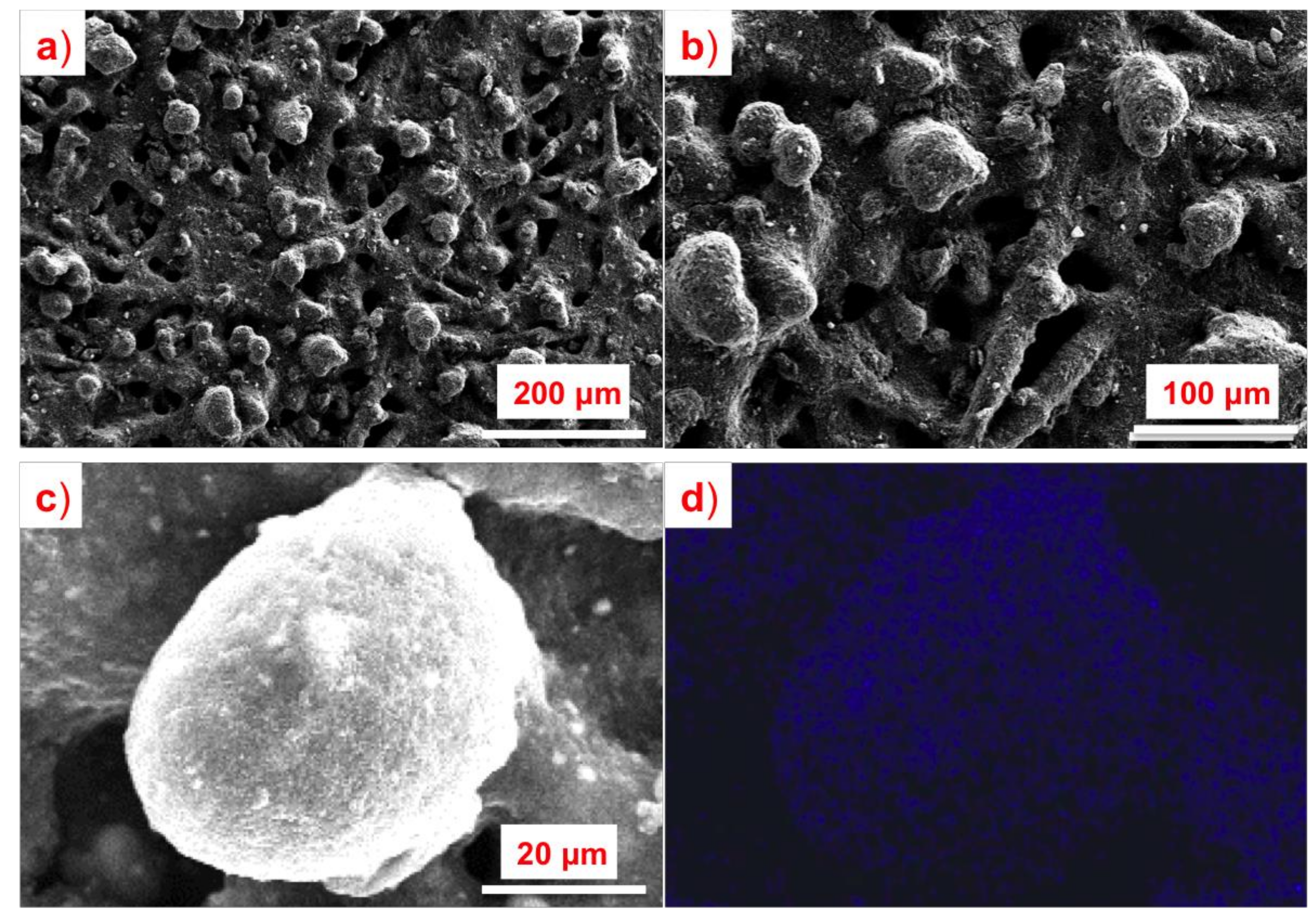
Next, the CF-VC catalysts were incorporated into gas diffusion electrodes (GDEs). To do this, the catalyst was mixed with a poly(ethylenetetrafluoroethylene) (ETFE) solid powder ionomer [14] (20 wt% ionomer), dispersed in solvent and sprayed onto Toray 60 gas diffusion layers as described in our previous publications [9,25,26,27]. The ETFE powder was used as the ionomer to support (along with the Vulcan carbon support) the formation of a porous electrode with facile product and reactant mass transport, which is important for AEMFC performance [26]. Scanning electron microscope (SEM) images of the CF-VC GDEs (Figure 5a,b) showed a uniform distribution of catalyst and ionomer particles as well as a very porous architecture. The ETFE ionomer appeared to be very well integrated with the CF-VC catalyst (Figure 5c), suggesting that these electrodes are likely to have a well-formed triple-phase boundary in operating AEMFCs. An energy-dispersive x-ray spectroscopy (EDS) fluorine elemental map for a typical catalyst-covered ionomer particle is shown in Figure 5d, which clearly shows the size, structure and distribution of the solid anionomer in the electrode.
The CF-VC GDEs were used as the cathode electrode in laboratory scale 5 cm2, single-cell AEMFCs. The CF-VC catalyst loading on the GDE was 2.4 mgCF/cm2. The anode electrode consisted of a PtRu/C catalyst and ETFE ionomer (20 wt% ionomer). The PtRu loading on the anode was very low, only 0.07 mgPtRu/cm2. The membrane used in this work was a radiation-grafted polyethylene-based film with a covalently-bound benzyltrimethylammonium (BTMA) cationic head-groups (25 μm; ion exchange capacity, IEC = 2.44 ± 0.04 mmol g−1). The development of this class of AEM was first reported in 2017 [28]. The operating AEMFCs were fed with pure H2 and O2 reacting gases, and the resulting CF-VC containing GDE was able to achieve a peak power density of 1350 mW cm−2 with a peak current density over 4 A cm−2 (Figure 6a), which is the best performance for an AEMFC with a non-PGM cathode reported in the literature to date [8,9,10,20,29,30]. Using H2 and air (CO2-free) reacting gases, the CF-VC non-PGM cathode GDE was able to achieve a peak power density of 670 mW cm−2 (Figure 6b). Compared to state-of-the-art non-PGM AEMFCs in the literature (Figure S2) [8,9,10,29], the CF-VC cell in this work showed greatly enhanced single-cell performance—despite lower intrinsic activity. The most impressive metrics for the CF-VC based AEMFC was its peak power density and mass transport limited current density. Again, both were the highest values reported in the literature to date, which was most likely due to the formation of a porous electrode architecture created by the combination of Vulcan carbon [9] and the solid powder anionomer, allowing for facile mass transport.
3. Materials and Methods
Chemicals: iron(II) acetate and cobalt(II) acetate tetrahydrate were purchased from Sigma-Aldrich (Delhi, India). Absolute ethanol and isopropyl alcohol were purchased from Thomas Baker (Delhi, India) and were used without any further purification. Deionized (DI) water was produced by a Millipore Milli-Q unit.
Synthesis of the cobalt ferrite (CF) nanoparticles: for the synthesis of the cobalt ferrite nanoparticles, cobalt acetate and iron acetate salts were dissolved in a 1:2 ratio in a solution of 1:1 (by volume) water-ethanol. 50 mL of the resulting solution was placed in a 100 mL autoclave, which was heated to 130 °C and maintained at that temperature for 12 h. A solid precipitate was obtained and separated from the solution supernatant by centrifugation. The solid was washed with a copious amount of ethanol. The sample was dried at 60 °C and the resulting cobalt ferrite (CF) nanoparticles [12] were used without any further treatment.
Synthesis of the cobalt ferrite/Vulcan carbon (CF-VC) catalyst: CF nanoparticles were first dispersed in a 3:2 water–isopropyl alcohol (IPA) solution. Then, Vulcan XC-72R carbon was added to the dispersion (1:1 ratio of CF and Vulcan carbon by weight), followed by sonication for 1 h. After this ensured that the CF and Vulcan carbon were well mixed, the solvent was evaporated and the solids were annealed at 150 °C for 12 h in air.
Glassy carbon RDE ink preparation and deposition: 10 mg of the catalyst was dispersed in 1 mL of a water–IPA solution (3:2) followed by the addition of 40 μL of 5% Nafion dispersion. 10 μL of the resulting ink was placed onto a glassy carbon RDE (0.196 cm2) and dried under an infrared (IR) lamp.
Material characterization: transmission electron microscopy (TEM) was performed using a FEI TECHNI (Delhi, India) G2 F20 instrument. The instrument was operated at 200 kV and has a resolution of 1.7 Å (Cs = 0.6 mm). Before TEM analysis, samples were drop-coated over a Cu grid and dried under an IR lamp. Powder X-ray diffraction analysis was performed with a PAN (Delhi, India) analytical X’pert Pro instrument equipped with a Cu Kα (λ = 1.54 Å) X-ray source. The samples were scanned for 30 min between 10 and 80 degrees (2θ). X-ray photoelectron spectroscopy (XPS) was performed with a Thermo Fisher Scientific (Delhi, India) instrument (Model: K ALPHA+) equipped with Mg Kα X-ray source (hν = 1.2356 keV). All of the RDE electrochemical studies were electrochemically controlled using a Biologic (Delhi, India) VMp3 instrument.
Koutecky–Levich analysis: the average number of electrons transferred during the ORR (n) was calculated from the Koutecky–Levich equations:
where j is the measured current density, jK is the kinetic current density, jL is the mass transport limited current density at a given rotation rate, is the angular velocity of the rotating disk, F is Faraday’s constant (96485.3 C/mol), Co is the bulk concentration of O2 in 0.1 M KOH at room temperature (1.2 × 10⁻⁶ mol/cm3), Do is the diffusion coefficient of O2 in 0.1 M KOH at room temperature (1.9 × 10⁻⁵ cm2/s), and is the kinematic viscosity for 0.1 M KOH (0.01 cm2/s).
Rotating ring-disk electrode (RRDE) measurements were made in the same RDE setup as mentioned above. The disk electrode was rotated at 1600 rpm with scan rate of 10 mV/s. The ring electrode potential was set to 1.1 V vs. RHE. The hydrogen peroxide yield (%H2O2) and average number of electrons transferred (n) were calculated by the following equations:
where id and ir are the disk and ring current densities, N is the ring H2O2 collection efficiency, which was 37%.
GDE fabrication and AEMFC testing: First, the ETFE-g-poly(VBTMAC) powder anionomer (IEC = 1.24 ± 0.06 mmol/g) [14] was ground with a well-cleaned mortar and pestle for 10 min to reduce the number of aggregated particles. Next, the catalyst and 1 mL of DI water was added to the ground anionomer and ground for an additional 10 min until a visually and texturally homogeneous slurry was formed. The ETFE powder mass comprised 20% of the total solid mass of all of the catalyst layers (CLs) in this study. After the slurry was homogenized, 1.5 mL of IPA was added into the mortar followed by another 5 min grinding. A final 5 mL of IPA was added to the mortar and the final ink mixture was transferred to a PTFE-lined vial and sonicated for 1 h in an ice bath. The prepared ink was then sprayed onto the gas diffusion layer (GDL, Toray 60, 5% PTFE wetproofing) using an air-assisted sprayer (Iwata Eclipse HP CS dual action airbrush gun; ANEST IWATA, Yokohama, Japan) to fabricate the GDEs. A Pt-Ru catalyst (Alfa Aesar, Haverhill, MA, USA, HiSPEC 10000, Pt nominally 40 wt%, and Ru, nominally 20 wt%, supported on Vulcan XC-72R carbon) was used at the anode. The anode GDEs, cathode GDEs and membrane were hydrated in DI water for 20 min and then soaked three times in aqueous 1.0 M KOH for a total of 1 h to remove impurities and ion exchange the quaternary ammonium hydroxide groups before cell assembly.
AEMFCs with 5 cm2 active area were assembled in single-cell hardware with a single channel, serpentine flow field. The anion exchange membranes used in this work were radiation-grafted polyethylene-based films with a covalently-bound benzyltrimethylammonium (BTMA) cationic head-groups (25 μm, IEC = 2.44 ± 0.04 mmol g−1). The average thickness of the anode and cathode were measured to be 216 and 270 μm, respectively. Thus, 152 and 203 μm Teflon gaskets were used on the anode and cathode, respectively, to keep the cell pinch at around 25% of the total GDE thickness. The AEMFCs were tested using a Scribner 850e fuel cell test station at a cell temperature of 65 °C under H2/O2 or H2/Air flow at 1.0 L/min. The cell was broken in at a voltage of 0.5 V and the relative humidity (RH) of both the cathode and anode were adjusted to allow the cell to be operated at optimal conditions [26].
4. Conclusions
In this work, a facile solvothermal method was used to prepare a cobalt-ferrite/Vulcan carbon (CF-VC) electrocatalyst for the oxygen reduction reaction in alkaline media. The CF-VC was well characterized through XRD, TEM and XPS. From the RDE measurements, the CF-VC catalyst showed good ex situ activity with a half-wave potential of 0.71 V (vs. RHE), as well as low peroxide yield with an overwhelming fraction of oxygen undergoing a complete four electron reduction. In operating AEMFCs, the CF-VC performed excellently, generating a peak power density of 1350 mW cm−2 under H2/O2—an unprecedented specific power density for a non-PGM cathode AEMFC.
Supplementary Materials
The following are available online at https://www.mdpi.com/2073-4344/9/3/264/s1, Figure S1: (a), (b) and (c) TEM images of the CF nanoparticles at higher magnification (20 and 10 nm scale bar). (d), (e) and (f) TEM image of the Vulcan carbon. (g), (h) and (i) TEM image of the CF-VC catalyst., Figure S2: Comparison of single cell performance and kinetic region (inset) between this work and state of the art non-PGM cathode fuel cell work. a), b) i-V curves and i-power density curves between this work and non-PM cathode FU [10], Fe/N/C nanotubes [8], N-C-CoOx[9] and CNT/PC [29] in AEMFC, Table S1: Binding energy of the cobalt and iron atoms in the XPS spectra of various catalysts.
Author Contributions
X.P. and V.K. contributed equally to this work. V.K. was responsible for the material synthesis and fundamental electrochemical experiments. X.P. was responsible for AEMFC assembly and testing, with some assistance from B.N. L.W. was responsible for the synthesis of the membranes. X.P. and W.E.M. were primarily responsible for the manuscript preparation. W.E.M., S.K. and J.R.V. were responsible for managing the overall research effort.
Funding
This research was funded by the U.S. Department of Energy Office of Energy Efficiency and Renewable Energy (award number Award Number: DE- EE0008433), University Grant Commission (UGC), New Delhi, India, for a Senior Research Fellowship and S.K. to Council of Scientific and Industrial Research (CSIR), New Delhi, India, for project grant TLP003526 and the UK’s Engineering and Physical Sciences Research Council (grant EP/M014371/1).
Acknowledgments
USC gratefully acknowledges the financial support of the U.S. Department of Energy Office of Energy Efficiency and Renewable Energy (award number Award Number: DE- EE0008433) for the effort expended by X.P. and W.E.M. to perform the fuel cell experiments and to prepare the manuscript. V.K. acknowledges University Grant Commission (UGC), New Delhi, India, for a Senior Research Fellowship and S.K. to Council of Scientific and Industrial Research (CSIR), New Delhi, India, for project grant TLP003526 to synthesize and characterize the CF-VC catalyst. The development and fabrication of the anion exchange membrane was funded by the UK’s Engineering and Physical Sciences Research Council (grant EP/M014371/1).
Conflicts of Interest
The authors declare no conflict of interest.
References
- Setzler, B.P.; Zhuang, Z.; Wittkopf, J.A.; Yan, Y. Activity targets for nanostructured platinum-group-metal-free catalysts in hydroxide exchange membrane fuel cells. Nat. Nanotechnol. 2016, 11, 1020–1025. [Google Scholar] [CrossRef] [PubMed]
- Nie, Y.; Li, L.; Wei, Z. Recent advancements in Pt and Pt-free catalysts for oxygen reduction reaction. Chem. Soc. Rev. 2015, 44, 2168–2201. [Google Scholar] [CrossRef] [PubMed]
- Guo, S.; Zhang, S.; Sun, S. Tuning nanoparticle catalysis for the oxygen reduction reaction. Angew. Chem. Int. Ed. 2013, 52, 8526–8544. [Google Scholar] [CrossRef] [PubMed]
- Li, Y.; Dai, H. Recent advances in zinc-air batteries. Chem. Soc. Rev. 2014, 43, 5257–5275. [Google Scholar] [CrossRef] [PubMed]
- Kraytsberg, A.; Ein-Eli, Y. Review of advanced materials for proton exchange membrane fuel cells. Energy Fuels 2014, 28, 7303–7330. [Google Scholar] [CrossRef]
- Wu, G.; More, K.L.; Johnston, C.M.; Piotr, Z. High-performance electrocatalysts for oxygen reduction derived from polyaniline, iron, and cobalt. Science 2011, 332, 443–448. [Google Scholar] [CrossRef] [PubMed]
- Kattel, S.; Atanassov, P.; Kiefer, B. A density functional theory study of oxygen reduction reaction on non-PGM Fe-Nx-C electrocatalysts. Phys. Chem. Chem. Phys. 2014, 16, 13800–13806. [Google Scholar] [CrossRef] [PubMed]
- Ren, H.; Wang, Y.; Yang, Y.; Tang, X.; Peng, Y.; Peng, H.; Xiao, L.; Lu, J.; Abruña, H.D.; Zhuang, L. Fe/N/C nanotubes with atomic Fe sites: A highly active cathode catalyst for alkaline polymer electrolyte fuel cells. ACS Catal. 2017, 7, 6485–6492. [Google Scholar] [CrossRef]
- Peng, X.; Omasta, T.J.; Magliocca, E.; Wang, L.; Varcoe, J.R.; Mustain, W.E. Nitrogen-doped carbon–CoOx nanohybrids: A precious metal free cathode that exceeds 1.0 W cm-2 peak power and 100 h life in anion- exchange membrane fuel cells. Angew. Chem. Int. Ed. 2019, 58, 1046–1051. [Google Scholar] [CrossRef] [PubMed]
- Lu, Y.; Wang, L.; Preuß, K.; Qiao, M.; Titirici, M.M.; Varcoe, J.; Cai, Q. Halloysite-derived nitrogen doped carbon electrocatalysts for anion exchange membrane fuel cells. J. Power Sour. 2017, 372, 82–90. [Google Scholar] [CrossRef] [Green Version]
- Liang, Y.; Li, Y.; Wang, H.; Zhou, J.; Wang, J.; Regier, T.; Dai, H. Co3O4 nanocrystals on graphene as a synergistic catalyst for oxygen reduction reaction. Nat. Mater. 2011, 10, 780–786. [Google Scholar] [CrossRef] [PubMed]
- Liang, Y.; Wang, H.; Zhou, J.; Li, Y.; Wang, J.; Regier, T.; Dai, H. Covalent hybrid of spinel manganese-cobalt oxide and graphene as advanced oxygen reduction electrocatalysts. J. Am. Chem. Soc. 2012, 134, 3517–3523. [Google Scholar] [CrossRef] [PubMed]
- Monzon, L.M.A.; Rode, K.; Venkatesan, M.; Coey, J.M.D. Electrosynthesis of iron, cobalt, and zinc microcrystals and magnetic enhancement of the oxygen reduction reaction. Chem. Mater. 2012, 24, 3878–3885. [Google Scholar] [CrossRef]
- Poynton, S.D.; Slade, R.C.T.; Omasta, T.J.; Mustain, W.E.; Escudero-Cid, R.; Ocón, P.; Varcoe, J.R. Preparation of radiation-grafted powders for use as anion exchange ionomers in alkaline polymer electrolyte fuel cells. J. Mater. Chem. A 2014, 2, 5124–5130. [Google Scholar] [CrossRef] [Green Version]
- Kashyap, V.; Singh, S.K.; Kurungot, S. Activity tuning of cobalt ferrite nanoparticles anchored on N-doped reduced graphene oxide as a potential oxygen reduction electrocatalyst by Zn substitution in the spinel matrix. Chem. Sel. 2017, 2, 7845–7853. [Google Scholar] [CrossRef]
- Tang, R.; Jiang, C.; Qian, W.; Jian, J.; Zhang, X.; Wang, H.; Yang, H. Dielectric relaxation, resonance and scaling behaviors in Sr3Co2Fe24O41 hexaferrite. Sci. Rep. 2015, 5, 1–11. [Google Scholar] [CrossRef] [PubMed]
- Zhang, X.; Qin, J.; Xue, Y.; Yu, P.; Zhang, B.; Wang, L.; Liu, R. Effect of aspect ratio and surface defects on the photocatalytic activity of ZnO nanorods. Sci. Rep. 2014, 4, 4–11. [Google Scholar] [CrossRef] [PubMed]
- Li, J.; Lu, G.; Wu, G.; Mao, D.; Guo, Y. Effect of TiO2 crystal structure on the catalytic performance of Co3O4/TiO2 catalyst for low-temperature CO oxidation. Catal. Sci. Technol. 2014, 4, 1268–1275. [Google Scholar] [CrossRef]
- Guan, B.Y.; Lu, Y.; Wang, Y.; Wu, M.; Lou, X.W.D. Porous iron-cobalt alloy/nitrogen-doped carbon cages synthesized via pyrolysis of complex metal-organic framework hybrids for oxygen reduction. Adv. Funct. Mater. 2018, 28, 1–10. [Google Scholar] [CrossRef]
- Hossen, M.M.; Artyushkova, K.; Atanassov, P.; Serov, A. Synthesis and characterization of high performing Fe-N-C catalyst for oxygen reduction reaction (ORR) in alkaline exchange membrane fuel cells. J. Power Sour. 2018, 375, 214–221. [Google Scholar] [CrossRef]
- Ahn, S.H.; Yu, X.; Manthiram, A. “Wiring” Fe-Nx-embedded porous carbon framework onto 1D nanotubes for efficient oxygen reduction reaction in alkaline and acidic media. Adv. Mater. 2017, 29, 1–10. [Google Scholar] [CrossRef] [PubMed]
- Chung, H.T.; Cullen, D.A.; Higgins, D.; Sneed, B.T.; Holby, E.F.; More, K.L.; Zelenay, P. Direct atomic-level insight into the active sites of a high-performance PGM-free ORR catalyst. Science 2017, 357, 479–484. [Google Scholar] [CrossRef] [PubMed]
- Palaniselvam, T.; Irshad, A.; Unni, B.; Kurungot, S. Activity modulated low platium content oxygen reduction electrocatalysts prepared by inducing nano-order dislocations on carbon nanofiber through N 2-doping. J. Phys. Chem. C 2012, 116, 14754–14763. [Google Scholar] [CrossRef]
- Balan, B.K.; Kurungot, S. Highly exposed and activity modulated sandwich type Pt thin layer catalyst with enhanced utilization. J. Mater. Chem. 2011, 21, 19039–19048. [Google Scholar] [CrossRef]
- Peng, X.; Omasta, T.J.; Roller, J.M.; Mustain, W.E. Highly active and durable Pd-Cu catalysts for oxygen reduction in alkaline exchange membrane fuel cells. Front. Energy 2017, 11, 299–309. [Google Scholar] [CrossRef]
- Omasta, T.J.; Wang, L.; Peng, X.; Lewis, C.A.; Varcoe, J.R.; Mustain, W.E. Importance of balancing membrane and electrode water in anion exchange membrane fuel cells. J. Power Sour. 2018, 375, 205–213. [Google Scholar] [CrossRef] [Green Version]
- Omasta, T.J.; Park, A.M.; LaManna, J.M.; Zhang, Y.; Peng, X.; Wang, L.; Jacobson, D.L.; Varcoe, J.R.; Hussey, D.S.; Pivovar, B.S.; et al. Beyond catalysis and membranes: Visualizing and solving the challenge of electrode water accumulation and flooding in AEMFCs. Energy Environ. Sci. 2018, 11, 551–558. [Google Scholar] [CrossRef]
- Wang, L.; Brink, J.J.; Liu, Y.; Herring, A.M.; Ponce-González, J.; Whelligan, D.K.; Varcoe, J.R. Non-fluorinated pre-irradiation-grafted (peroxidated) LDPE-based anion-exchange membranes with high performance and stability. Energy Environ. Sci. 2017, 10, 2154–2167. [Google Scholar] [CrossRef] [Green Version]
- Sa, Y.J.; Seo, D.-J.; Woo, J.; Lim, J.T.; Cheon, J.Y.; Yang, S.Y.; Lee, J.M.; Kang, D.; Shin, T.J.; Shin, H.S.; et al. A general approach to preferential formation of active Fe-Nx sites in Fe-N/C electrocatalysts for efficient oxygen reduction reaction. J. Am. Chem. Soc. 2016, 138, 15046–15056. [Google Scholar] [CrossRef] [PubMed]
- Serov, P.I.A. Development of PGM-Free Catalysts for Hydrogen Oxidation Reaction in Alkaline Media; University of New Mexico: Albuquerque, NM, USA, 2016. [Google Scholar]
Figure 1.
(a,b) Transmission electron microscopy (TEM) images of the cobalt ferrite (CF) nanoparticles at different magnification. The inset in (b) shows a line profile corresponding to the (311) plane of the cobalt ferrite. (c) TEM image of the CF-VC catalyst showing the size and distribution of the CF and Vulcan carbon. (d,e) Particle size distribution analysis of the CF-VC catalyst showing CF and Vulcan carbon, respectively.

Figure 2.
Powder diffraction patterns for cobalt ferrite (CF) nanoparticles, the CF-VC composite catalyst and CoFe2O4 (JCPDS 22-1086).
Figure 2.
Powder diffraction patterns for cobalt ferrite (CF) nanoparticles, the CF-VC composite catalyst and CoFe2O4 (JCPDS 22-1086).

Figure 3.
(a) X-ray photoelectron spectroscopy (XPS) survey spectra for raw CF and the CF-VC catalyst. (b) Deconvoluted oxygen 1s spectra in CF and CF-VC. (c,d) Deconvoluted Co and Fe 2p spectra, respectively.
Figure 3.
(a) X-ray photoelectron spectroscopy (XPS) survey spectra for raw CF and the CF-VC catalyst. (b) Deconvoluted oxygen 1s spectra in CF and CF-VC. (c,d) Deconvoluted Co and Fe 2p spectra, respectively.

Figure 4.
(a) Cyclic voltammograms for CF nanoparticles and the CF-VC catalyst in 0.1 M KOH electrolyte at a scan rate of 50 mV/s (nitrogen saturated = black; oxygen saturated = green and red). (b) Linear sweep voltamograms (LSV) for the CF-VC catalyst at various rotation rates in oxygen saturated, 0.1 M KOH. A K–L plot from the LSV data is shown as the inset in (b). (c) Percentage of peroxide formed at various electrode potentials for CF, CF-VC and 20% Pt/C catalyst. (d) Number of electrons transferred during the oxygen reduction reaction (ORR) for CF, CF-VC and 20% Pt/C as a function of electrode potential.

Figure 5.
(a,b) Scanning electron microscope (SEM) images of the cathode gas diffusion electrode (GDE) with a CF-VC catalyst and a poly(ethylenetetrafluoroethylene) (ETFE) powder deposited onto Toray-60 carbon paper under different magnifications; (c) SEM images showing that the ETFE ionomer was wrapped by the CF-VC; (d) corresponding fluorine mapping of the image in (c) showing the ionomer.

Figure 6.
CF-VC anion exchange membrane fuel cell (AEMFC) polarization curves and power density in two configurations operated at 70 °C. (a) H2-O2 gases fed at 1 L/min, RHanode = 73%, RHcathode = 90% without backpressure; (b) H2-air (CO2-free) at 1 L/min; anode: 0.7 mgPtRu cm−2, RH = 76%, 0.03 Mpa backpressure; Cathode: 2.4 mg cm−2 CF-VC, RH = 93%, 0.1 MPa backpressure., The membrane in this work was a polyethylene-based radiation-grafted anion exchange membrane (IEC = 2.44 ± 0.04 mmol g−1) and the anionomer was ETFE-benzyltrimethylammonium (BTMA) powder [14] (IEC = 1.24 ± 0.06 mmol g−1). (RH = relative humidity)

© 2019 by the authors. Licensee MDPI, Basel, Switzerland. This article is an open access article distributed under the terms and conditions of the Creative Commons Attribution (CC BY) license (http://creativecommons.org/licenses/by/4.0/).
Share and Cite
MDPI and ACS Style
Peng, X.; Kashyap, V.; Ng, B.; Kurungot, S.; Wang, L.; Varcoe, J.R.; Mustain, W.E. High-Performing PGM-Free AEMFC Cathodes from Carbon-Supported Cobalt Ferrite Nanoparticles. Catalysts 2019, 9, 264. https://doi.org/10.3390/catal9030264
AMA Style
Peng X, Kashyap V, Ng B, Kurungot S, Wang L, Varcoe JR, Mustain WE. High-Performing PGM-Free AEMFC Cathodes from Carbon-Supported Cobalt Ferrite Nanoparticles. Catalysts. 2019; 9(3):264. https://doi.org/10.3390/catal9030264
Chicago/Turabian StylePeng, Xiong, Varchaswal Kashyap, Benjamin Ng, Sreekumar Kurungot, Lianqin Wang, John R. Varcoe, and William E. Mustain. 2019. "High-Performing PGM-Free AEMFC Cathodes from Carbon-Supported Cobalt Ferrite Nanoparticles" Catalysts 9, no. 3: 264. https://doi.org/10.3390/catal9030264
Note that from the first issue of 2016, this journal uses article numbers instead of page numbers. See further details here.