
Three-Dimensional TiO2 Structures Incorporated with Tungsten Oxide for Treatment of Toxic Aromatic Volatile Compounds

Department of Environmental Engineering, Kyungpook National University, Daegu 702-701, Korea
*
Author to whom correspondence should be addressed.
Catalysts 2017, 7(4), 97; https://doi.org/10.3390/catal7040097
Submission received: 24 February 2017
/
Revised: 16 March 2017
/
Accepted: 20 March 2017
/
Published: 23 March 2017
(This article belongs to the Special Issue Heterogeneous Catalysis for Environmental Remediation)
Abstract
:This study assessed 3D WO3–TiO2 nanoflowers (WTNF) synthesized by a combined hydrothermal–ultrasonication–impregnation method for their applicability to the treatment of aromatic volatile compounds under visible-light illumination. The scanning electron microscopy exhibited the formation of 3D structures in the prepared WTNF samples. The X-ray diffraction patterns and energy dispersive X-ray results indicated a successful incorporation of WO3 into TNF structures. The UV-visible spectroscopy showed that the prepared WTNF samples can be functioned under visible light irradiation. The output-to-input concentration ratios of toluene and o-xylene with WTNF samples were lower than those of TiO2 nanoflowers. These findings were illustrated on the basis of charge separation ability, adsorption capability, and light absorption of the sample photocatalysts. The input-to-output concentration ratios of the target chemicals were lowest for 10 M NaOH and highest for 5 M NaOH. The photocatalytic degradation efficiencies of WTNF sample photocatalysts increased with increasing WO3 content from 0.1% to 1.0%, and dropped gradually with increasing WO3 content further to 4.0%. Light-emitting-diodes (LEDs) are a more highly energy-efficient light source compared to a conventional lamp for the photocatalytic degradation of toluene and o-xylene, although the photocatalytic activity is higher for the conventional lamp.
1. Introduction
Exposure to aromatic volatile compounds indoors has become an important environmental issue because it is closely linked to the adverse health risk of building occupants. There are a wide range of indoor sources of aromatic pollutants, such as building finishing materials, furniture, and household products, resulting in higher indoor pollution for these pollutants relative to outdoor concentrations [1]. Most aromatic volatile compounds display high carcinogenic chronic effects and non-carcinogenic chronic effects such as damage to liver, kidneys, the central nervous system, and the respiratory system [2,3]. Moreover, many people spend most of their personal time in indoor environments, thus justifying the application of mitigation strategies for indoor aromatic volatile compound concentrations to reduce the health risks of building occupants.
The photocatalysis of titanium dioxide (TiO2) is an advanced oxidation method that can efficiently be applied in the treatment of a variety of environmental pollutants [4,5,6,7,8,9]. Nevertheless, the environmental application of TiO2 is obstructed by a wide band gap, which is restricted to the ultraviolet (UV) region [6,8,10]. Photocatalysis of TiO2 is also hampered by high recombination rates of charge carriers, thus resulting in a low quantum yield [6]. To solve these problems, a great deal of techniques have been developed to modify the surface characteristics of TiO2 [11]. The surface modification of TiO2 with tungsten trioxide (WO3), which is a narrow-band gap semiconductor (2.4–2.8 eV), is an interesting technique for expanding the light absorbance capability of TiO2 to the visible range [12,13]. WO3 can act as an electron acceptor, thus lowering the recombination rate of photoinduced electrons and holes on the surface and bulk spaces of TiO2 and elevating its photocatalytic activity [14]. The electron acceptation by WO3 was ascribed to a fast reaction rate of W6+ to W5+. Additionally, in recent studies, WO3-incorporated TiO2 powders revealed higher photocatalytic activity compared to pure TiO2 for the destruction of certain water and air pollutants with visible light or UV exposure [12,14,15,16].
Conversion of TiO2 structural dimension is also a potential technique for the enhancement of photocatalytic activity of TiO2 since it affects the movement of electrons and holes, light applicability, and adsorption capacity [17]. Previous researchers have prepared one-dimensional titanate nanowires and two-dimensional TiO2 nanosheets to enhance the functional properties of TiO2 [18,19]. Horváth et al. [20] noted that some of titanate compounds are not active as photocatalysts under certain conditions. In particular, a three-dimensional (3D) photocatalyst exhibits a high surface area-to-volume proportion, accelerating the movement of charge carriers and the transport of pollutant molecules to the surface of photocatalyst, and increasing light absorbance capacity [17,21]. Some researchers have found that 3D TiO2-incorporated architectures had a higher photocatalytic activity relative to that of zero-dimensional (0D) TiO2-incorporated architectures for the treatment of aqueous-phase p-chlorophenol, methylene blue, methyl orange, and rhodamine B [22,23,24,25].
With the merits of WO3 incorporation into TiO2 (WO3‒TiO2) and 3D TiO2 for photocatalytic activities, their combination is proposed to provide a synergistic effect for the treatment of environmental pollutants. Unfortunately, the applicability of 3D WO3‒TiO2 hybrids to gas-phase pollutant treatments is hardly reported in scientific literature. Accordingly, in this study, 3D WO3‒TiO2 nanoflowers (WTNF) were synthesized using a combined hydrothermal–ultrasonication–impregnation method to examine their applicability to the treatment of aromatic volatile compounds under visible light illumination. The photocatalytic treatment tests were performed under different conditions by varying the amount of WO3 content, the concentration of NaOH, and the light source. The amount of semiconductors incorporated into TiO2 is an important parameter for the photocatalytic activity of semiconductor-embedded TiO2 hybrids [26]. Additionally, the concentration of NaOH, which is used during the ultrasonication process, can also influence the formation of 3D architectures and thus their photocatalytic activities for the degradation of aromatic volatile compounds [27]. Light source type is another important parameter for the photocatalytic performance of many photocatalysts [28]. For comparison, a reference photocatalyst (3D TiO2 nanoflower sample, TNF) was additionally prepared, and its characteristics and photocatalytic activity were investigated.
2. Results and Discussion
2.1. Fabricated Photocatalysts
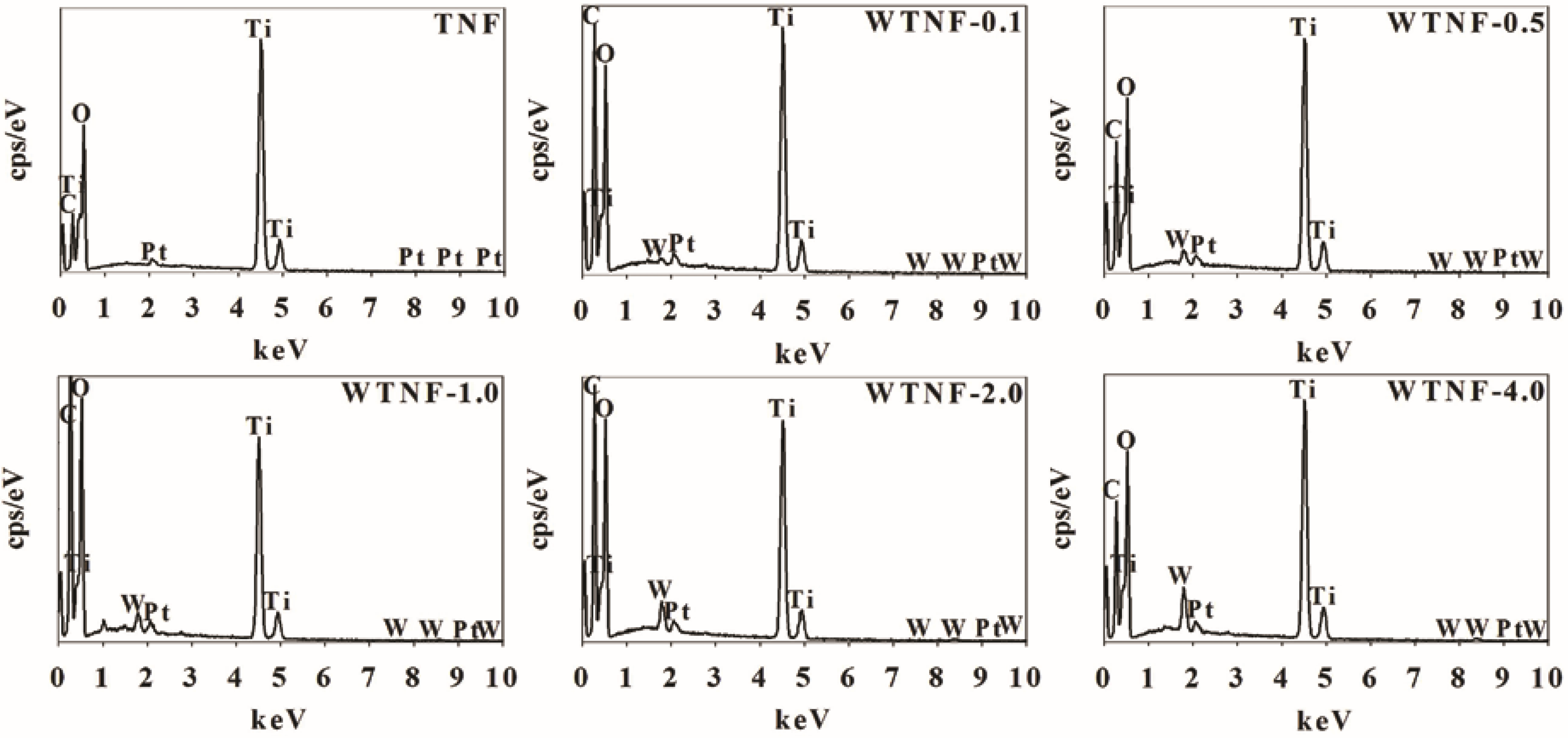
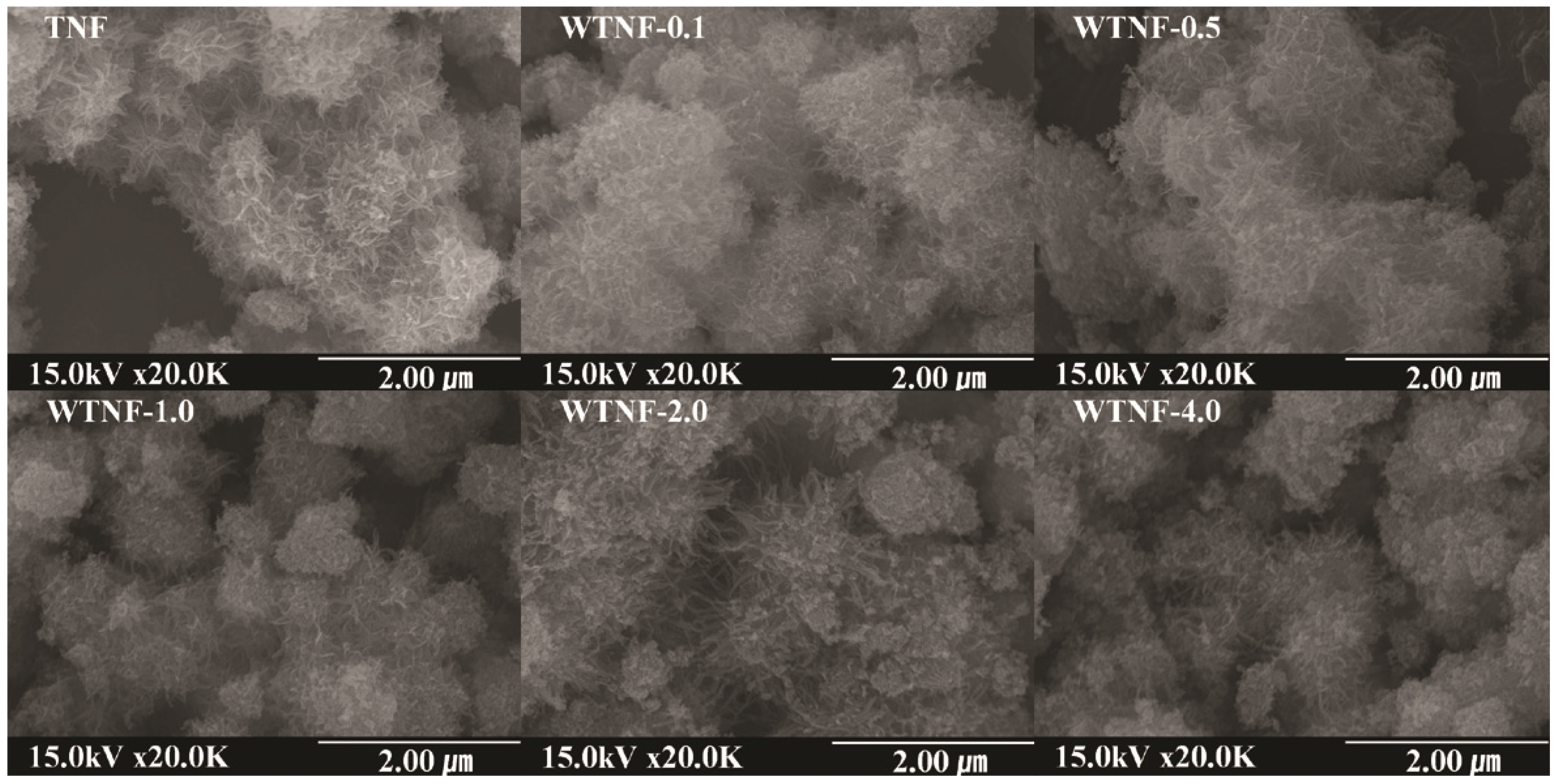
The natures of the fabricated samples were inspected by XRD analysis, SEM/EDX, and UV-visible spectroscopy. Figure 1 shows the powder XRD results of pure TiO2 nanoflowers (TNF) and WO3‒TiO2 nanoflowers with different WO3 loadings (WTNF-0.1, WTNF-0.5, WTNF-1.0, WTNF-2.0, and WTNF-4.0). All the samples revealed both anatase and rutile phase peaks with a primary peak at 2θ = 25.34° corresponding to the (101) plane and a large peak at 2θ = 27.29° corresponding to the (110) plane, respectively. These patterns are similar to the XRD results obtained from commercial P25 TiO2, which were reported in previous studies [29,30]. Notably, WTNF-4.0 exhibited additional two peaks at 2θ = 24.19° corresponding to the (110) plane and at 2θ = 49.91° corresponding to the (220) plane. These findings indicate that WO3 was successfully incorporated into TiO2 structures in the WTNF-4.0. This assertion is supported by EDX images (Figure 2), which display the presence of WO3 in all WTNF samples. Meanwhile, there were no WO3-associated peaks for TNF. The EDX images shows that the WTNF samples consist of Ti and WO3 elements, whereas the TNF samples consist only of Ti elements. Pt elements shown in the XRD images of all samples are ascribed to a Pt coating for a sample pretreatment process. However, other WTNF samples with small WO3 concentrations of 2.0% or less (WTNF-0.1, WTNF-0.5, WTNF-1.0, and WTNF-2.0) did not reveal WO3 peaks in their XRD images. These results are most likely due to low amounts of WO3 that cannot be detected by the analytical instrument used in this study. Additionally, Figure 3 depicts the SEM images of the prepared sample photocatalysts. All samples exhibited 3D nanoflower structures, regardless of the incorporation of WO3 or not. As such, these results suggest that the combined hydrothermal–ultrasonication–impregnation method employed in this study can be applied for the synthesis 3D WTNF samples.
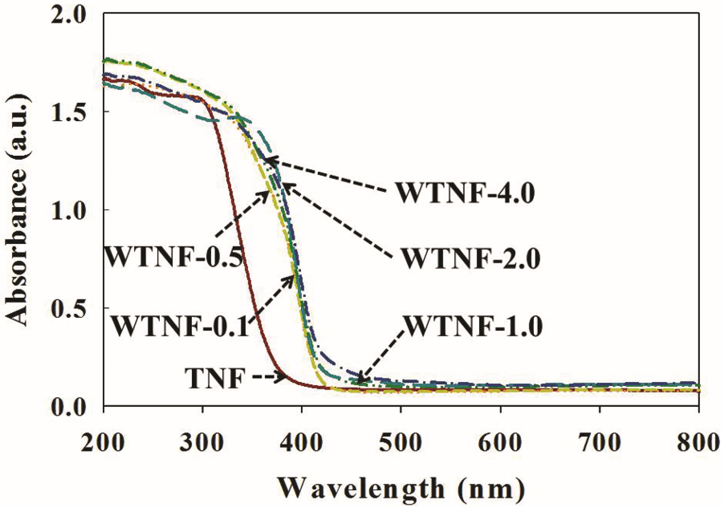
The UV-visible absorption spectra of the sample photocatalysts were determined to examine the characteristics of their electronic structures (Figure 4). Unmodified 3D TiO2 structures (TNF) revealed a high absorption property in the UV region with a band gap edge at 3.30 eV, but no significant absorbance in the visible range (Table 1), which was in accordance with the results of TiO2 powder, which were reported in previous studies [31,32]. On the contrary, the UV-visible spectra of the WTNF samples revealed broad light absorbance in a band gap range from 2.92 to 2.97 eV (Table 1). Moreover, the absorption intensities in the visible range became greater for WTNF samples with high WO3 concentrations, which likely is due to the embedded WO3 that changes the electronic and surface natures of TiO2 structures [14]. For WTNF samples, electrons excited from the valence band of WO3 to its conduction band under visible light illumination are transferred to the conduction band of TiO2, thus increasing their visible light absorption. Accordingly, the UV-visible absorption results of the WTNF samples indicate that the fabricated architectures can be efficiently functioned for the degradation of aromatic volatile compounds with exposure to visible light.
2.2. Photocatalytic Activity of Sample Photocatalysts
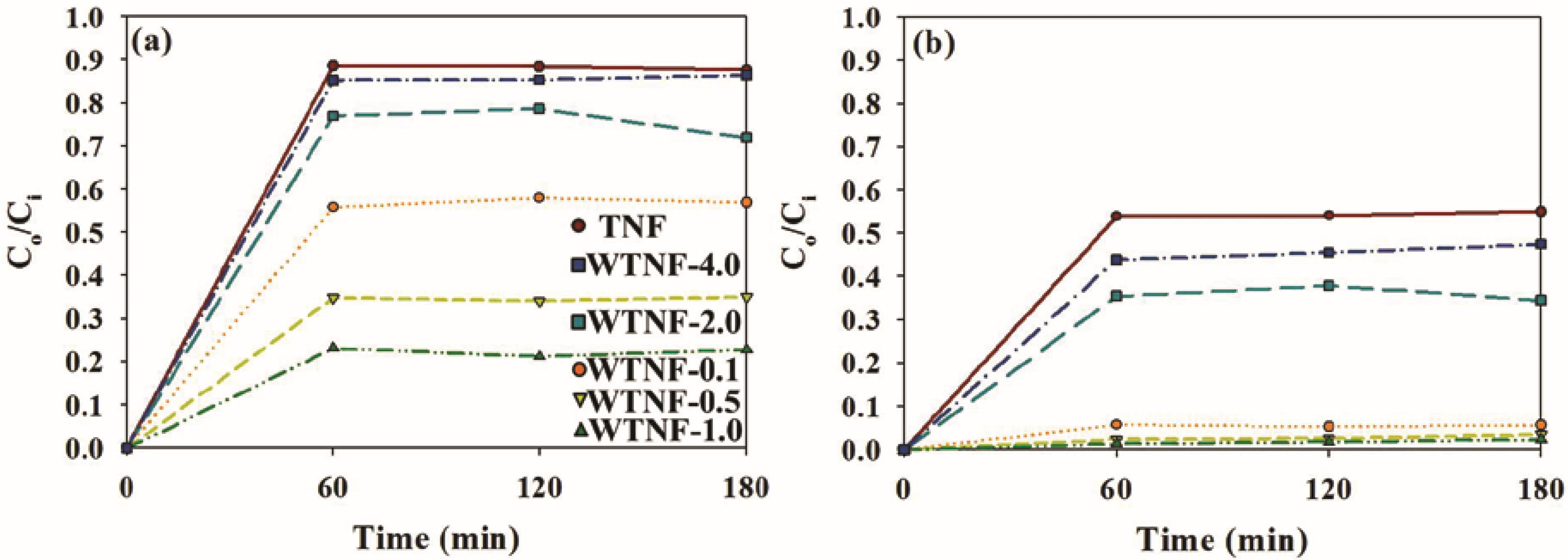
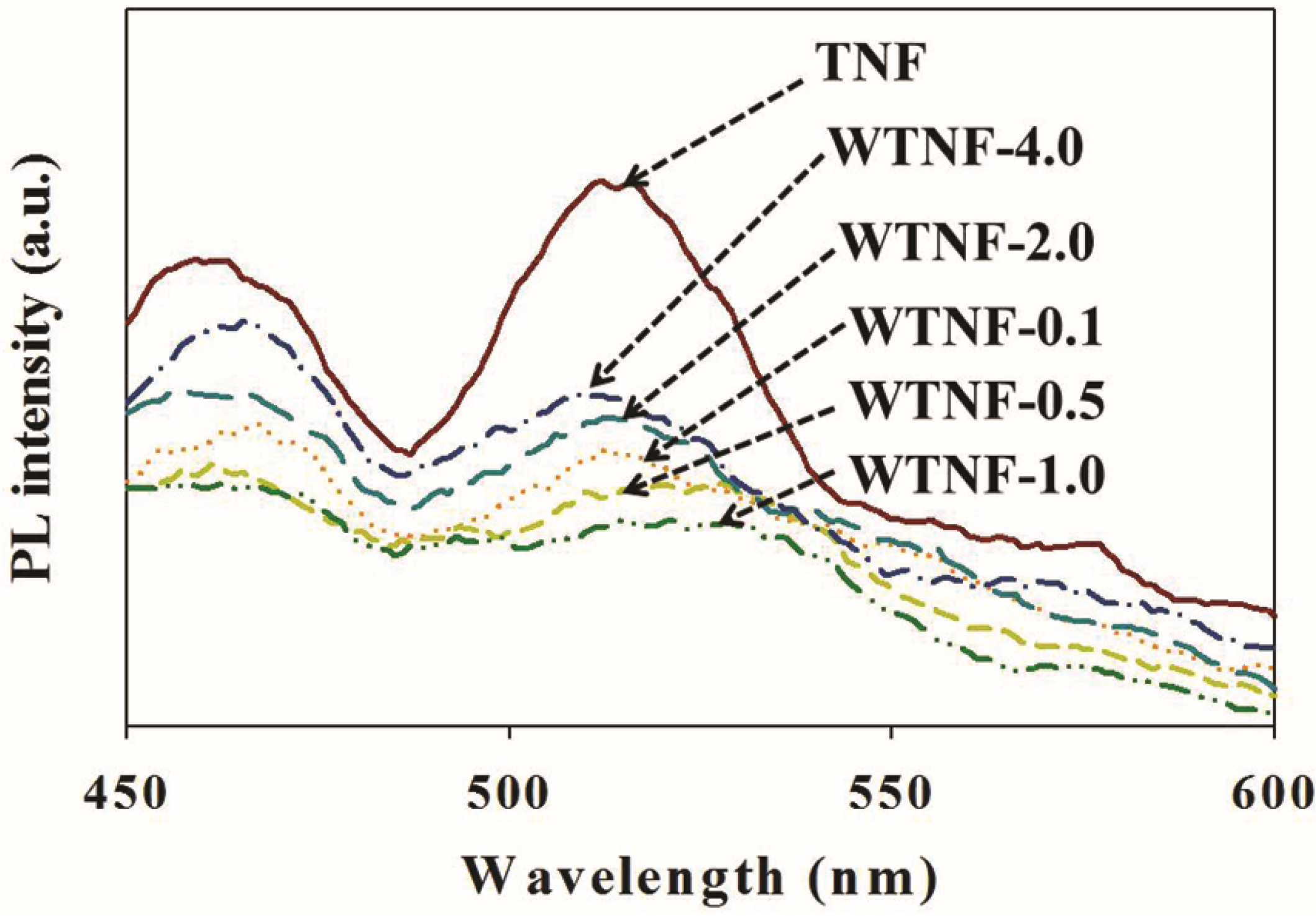
The photocatalytic activity of the sample photocatalysts was surveyed for the degradation of selected aromatic volatile compounds under different operating conditions. Using an uncoated Pyrex reactor with illumination, no discernible degradation of the aromatic volatile compounds were observed. Equilibrium in the concentrations of toluene and o-xylene on the catalyst surface was achieved within 1 h after gas flows. Figure 5 depicts the photocatalytic degradation efficiencies of TNF and WTNF samples with different WO3 loadings, which were obtained after observing equilibrium in concentrations of the target chemicals. The output-to-input concentration ratios of WTNF samples were lower than those of TNF, indicating that the degradation efficiencies of the former samples were higher than those of the latter. These findings are illustrated on the basis of charge separation ability, adsorption capability, and light absorption of the sample photocatalysts. The PL emission intensity displayed in Figure 6 shows that the WTNF samples possessed greater charge separation abilities relative to TNF, because high PL emission intensity typically represents a high recombination rate of electron and hole pairs [22,33]. The specific surface areas and total pore volumes of some WTNF samples (WTNF-0.1 and WTNF-0.5) were higher than the corresponding values of the TNF sample, which leads to higher adsorption capacities for WTNF samples (Table 1). In addition, WTNF samples displayed a higher absorption intensity in the visible range compared to TNF (Figure 4).
Figure 5 also shows that the photocatalytic degradation efficiencies of WTNF sample photocatalysts increased with increasing WO3 content from 0.1% to 1.0%, and dropped gradually with increasing WO3 content further to 4.0%. These results indicate that there is an optimal WO3 content for the preparation of WTNF sample photocatalysts. The order of WTNF samples in photocatalytic degradation efficiency was the same as that of charge separation efficiency (Figure 6). Specifically, WTNF-1.0 displayed the highest charge separation efficiency, while WTNF-4.0 showed the least efficiency among the surveyed WTNF samples. Adsorption capacity and light absorption of WTNF sample photocatalysts were in the same order of their photocatalytic degradation efficiencies (Table 1 and Figure 4, respectively).
The effects of photocatalytic operating conditions on the degradation efficiency were investigated using WTNF-1.0, which exhibited the highest photocatalytic activity among the WTNF samples. Figure 7 shows the photocatalytic degradation efficiencies of toluene and o-xylene with WTNF-1.0 according to NaOH concentrations used for an ultrasound process. Specifically, the input-to-output concentration ratios of the target chemicals were lowest for 10 M NaOH and highest for 5 M NaOH, indicating that the photocatalytic degradation efficiency was highest for the former and lowest for the latter. These results indicate that there is an optimal WO3 content for the preparation of WTNF sample photocatalysts. The higher photocatalytic degradation efficiency for WTNF-1.0 prepared using a higher NaOH concentration (10 M) is attributed to better 3D nanoflower structures, which were shown in our preliminary study. In addition, Figure 8 shows the photocatalytic degradation efficiencies of toluene and o-xylene with WTNF-1.0 according to light source (conventional daylight lamp and white and violet LEDs). The input-to-output concentration ratio of the target chemicals with the conventional daylight lamp was lower than those of the white and violet LEDs, indicating a higher photocatalytic efficiency for the former light source. These findings are ascribed to the higher light power of the conventional daylight lamp (8 W power and 400–720 nm wavelength) compared to the white (0.32 W and 450 nm wavelength) and violet LEDs (0.32 W and 400 nm wavelength). However, the photocatalytic degradation efficiencies normalized to supplied electric powers were higher for the LEDs than for the conventional daylight lamp: white LED, 0.16 and 0.34%/W for toluene and o-xylene, respectively; violet LED, 0.28 and 1.25%/W for toluene and o-xylene, respectively; conventional daylight lamp, 0.10 and 0.12%/W for toluene and o-xylene, respectively. These results indicate that LEDs are a more highly energy-efficient light source for the photocatalytic degradation of toluene and o-xylene with WTNF-1.0, although the photocatalytic activity is higher for the conventional daylight lamp.
A suggested photocatalytic degradation mechanism of toluene and o-xylene with WTNF sample photocatalysts is further described. Under a light exposure exceeding the band gap of WO3, the electron generated in the valence band of WO3 is transferred to the conduction band of WO3. This transferred electron can again be moved to the conduction band of TNF due to the lower band gap position of TNF. The positive holes in the valence band of WO3 react with OH‒ and H2O to produce·OH, and the photoinduced and transferred electrons react with O2 to generate·O2‒. The reactive OH and·O2‒ then react with limonene and toluene to produce CO2, CO, and other byproducts.
3. Materials and Methods
3.1. Preparation of Samples
The procedure for the synthesis of 3D WO3‒TiO2 hybrids with different WO3 concentrations is summarized as follows: the preparation of TiO2 powder, morphological transformation of TiO2 powder into TNF (a reference photocatalyst), and embedment of WO3 into 3D TiO2 nanoflowers. For the preparation of TiO2 powder, 2.0 g of Surfactant P-123 (Sigma-Aldrich, Milwaukee, WI, USA) was mixed with 400 mL of deionized water and stirred for 30 min, after which 120 mL of titanium IV isopropoxide (TTIP, Sigma-Aldrich) was added to the mixture and stirred for another 30 min. The suspension was ultrasonicated for 90 min, conditioned overnight at room temperature, and centrifuged at 2000 rpm for 20 min. The solid products were dried at 80 °C for 15 h and calcined at 550 °C for 1 h to provide TiO2 powders.
The fabricated TiO2 powders were hydrothermally and ultrasonically treated to obtain 3D TiO2 structures. Titanium tetrachloride (TiCL4, Sigma-Aldrich) (50 mL), 70 mL of NaOH (5, 10, 15 or 20 M) (Sigma-Aldrich), and 25 mL of H2O2 (30%) (Sigma-Aldrich) was mixed with 300 mL of deionized water. TiO2 powders (220 mg) were added to this solution, before it was hydrothermally treated in an autoclave at 90 °C for 3 h. Then, this mixture was centrifuged at 10,000 rpm for 15 min, after which the products were mixed with the 400 mL of HCL (Sigma-Aldrich). This suspension was ultrasonicated for 40 min using an ultrasonicator (VCX750, Sonics & Materials, Newtown, CT, USA). The precipitates were cleaned using distilled water and ethanol (Sigma-Aldrich), and the cleaned output was then dried at 50 °C for 20 h and calcined at 550 °C for 1 h to obtain 3D TiO2 structures.
WTNFs were fabricated by embedding WO3 into 3D TiO2 structures. A pre-scheduled amount of pentahydrated ammonium paratungstate ((NH4)10W12O41·5H2O, Sigma-Aldrich) was added to a solution of C2H5OH (10 mL) and distilled water (30 mL). Three-dimensional TiO2 powder (1 g) was added to the solution and stirred for 15 h. Then, this mixture was conditioned in a dry oven (110 °C) for 2 h, dried at 380 °C for 2 h, and calcined at 550 °C for 1 h to produce WTNF samples. During the drying and calcination processes, WO3 was formed by the reaction of (NH4)10W12O41·5H2O and incorporated into TiO2 structures. The amounts of ((NH4)10W12O41·5H2O were 0.08, 0.40, 0.80, 0.16, and 0.32 g, which were determined to obtain WTNFs with WO3-to-TiO2 percentages of 0.1%, 0.5%, 1.0%, 2.0% and 4.0%, respectively (They are denoted here as WTNF-0.1, WTNF-0.5, WTNF-1.0, WTNF-2.0, and WTNF-4.0, respectively).
The properties of the synthesized samples were examined using X-ray diffraction (XRD, Rigaku D/max-2500 diffractometer, Rigaku Corp., Tokyo, Japan), scanning electron microscopy/energy dispersive X-ray (SEM, Hitachi S-4300 & EDX-350 FE, Hitachi, Tokyo, Japan), photoluminescence emission spectroscopy (PL, SpectraPro 2150i, Acton Research, Princeton, NJ, USA), UV-visible spectroscopy (Varian CARY 5G, Varian, Cary, NC, USA), and N2 physisorption (ASAP 2020, Micromeritics, Norcross, GA, USA).
3.2. Photocatalysis of Aromatic Compounds
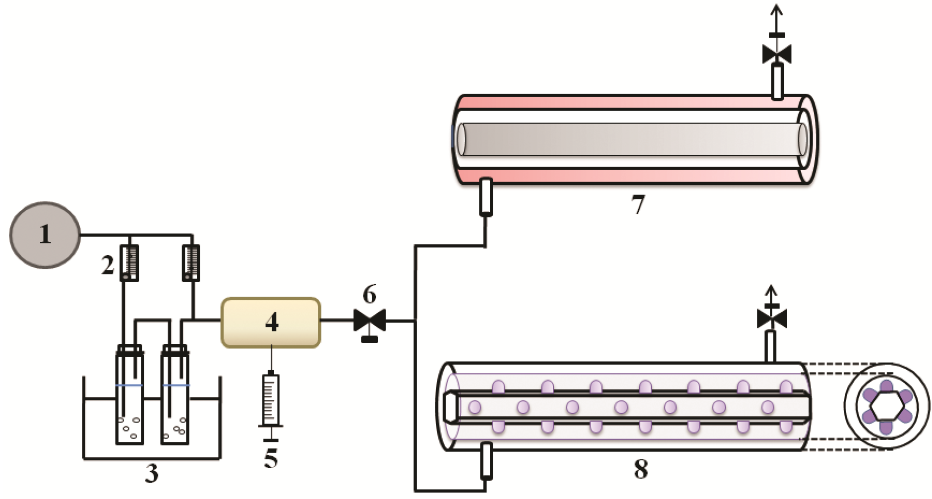
The experimental setup for the photocatalytic tests of the prepared photocatalysts is shown in Figure 9. Major components of the experimental system include an air cylinder for clean air supply, rotameters for flow measurements, a water bath for humidification, a heated chamber for mixing of air and standard substrates, a syringe pump for automatic injection of target compounds, a 3-way valve for gas sampling, and a photocatalytic reactor with a conventional lamp or a photocatalytic reactor with white or violet LEDs. A dipping method was applied for the coating of the reactor with individual photocatalyst samples. Clean air supplied from the air cylinder was passed through the water bath unit for humidification at a specified relative humidity. The humidified air was delivered into the reactor with a direction perpendicular to the reactor in order to increase the mass transport of incoming gas to the catalyst surface. The photocatalytic operating conditions were adjusted as follows: sample amounts coated onto the inner wall of the reactor, 0.45 mg cm−2; input concentration of target chemicals, 0.1 ppm; relative humidity, 40%; gas flow rate, 1.0 L min−1.
Before conducting main photocatalytic experiments, the experimental system was cleaned using clean air overnight while light illumination to degrade any compounds attached to the system. An uncoated reactor was exposed to visible light in order investigate the effect of light on the degradation of the target chemicals. Adsorption equilibrium of aromatic volatile compounds between the photocatalyst and gas was checked by examining if the chemical concentrations were equal in input and output air. Once the adsorption equilibrium was identified, the light source was turned on to start the main photocatalytic experiments.
Air samples for the measurements of aromatic volatile compounds and other organic vaporous compounds were obtained at upstream and downstream sampling ports of the photocatalytic reactor. Air sampling was carried out by drawing air from the sampling ports to Tenax GC-contained tube to concentrate target chemicals. A thermal desorption unit (ATD 350, Perkin Elmer, Waltham, MA, USA) was employed to transfer sampled compounds to a gas chromatograph/mass spectrometer (GC/MS) (Clarus 680, Perkin Elmer, Waltham; Clarus SQ8 T, Perkin Elmer, Waltham) for analysis. The adsorbent tube was thermally treated at 260 °C for 12 min, and the chemical species were concentrated at −30 °C on an internal trap. Subsequently, the internal trap was heated to 250 °C to deliver the chemical species to the analytical system. The initial temperature in the GC oven was adjusted at 40 °C for 6 min and ramped at 5 °C/min to 220 °C for 3 min. A contro analysis showed no co-eluting compounds during entire analytical processes. The quantitative determination of chemical species was done based on the calibration equations established using at least five different concentrations. For the quality control for sample analyses, blank samples were examined to check sample contamination, and spiked samples were investigated to check any analysis variation. The minimum detection thresholds varied between 0.5 and 1.3 ppb, depending on compound.
4. Conclusions
In the present study, WTNF composites with different WO3 concentrations were fabricated and their photocatalytic activity for treatment of toluene and o-xylene at an indoor concentration under visible light exposure was surveyed. The spectral results demonstrated the formation of 3D structures in the prepared WTNF samples, the incorporation of WO3 into TNF structures, and the potential activity of WTNF sample photocatalysts under visible light irradiation. WTNF samples exhibited superior photocatalytic function to the reference TNF sample for degradation of indoor-level toluene and o-xylene with visible light exposure. The photocatalytic degradation efficiencies of WTNF composites depended upon the WO3-to-TiO2 ratios. There was an optimal NaOH concentration for the preparation of WTNF photocatalysts using an ultrasound treatment process. LEDs are suggested as an energy-efficient light source for the photocatalytic degradation of toluene and o-xylene with WTNF samples. Overall, WTNF photocatalysts prepared by the combined hydrothermal–ultrasonication–impregnation method can be applied for the treatment of indoor level aromatic volatile pollutants.
Acknowledgments
This work was supported by the National Research Foundation of Korea grant funded by the Korea government (Ministry of Science and Future Planning) (No. 2016R1A2B4009122).
Author Contributions
Wan-Kuen Jo conceived and designed the experiments; Joon Yeob Lee performed the experiments; Wan-Kuen Jo and Joon Yeob Lee analyzed the data.
Conflicts of Interest
The authors declare no conflict of interest.
References
- Su, F.-C.; Mukherjee, B.; Batterman, S. Determinants of personal, indoor and outdoor VOC concentrations: An analysis of the RIOPA data. Environ. Res. 2013, 126, 192–203. [Google Scholar] [CrossRef] [PubMed]
- Ramírez, N.; Cuadras, A.; Rovira, E.; Borrull, F.; Marcé, R.M. Chronic risk assessment of exposure to volatile organic compounds in the atmosphere near the largest Mediterranean industrial site. Environ. Int. 2012, 39, 200–209. [Google Scholar] [CrossRef] [PubMed]
- IARC (International Agency for Research on Cancer). Monographs on the Evaluation of the Carcinogenic Risks to Humans. Available online: http://monographs.iarc.fr/ENG/Classification/index.php (accessed on 5 January 2016).
- Grabowska, E.; Reszczyńska, J.; Zaleska, A. Mechanism of phenol photodegradation in the presence of pure and modified-TiO2: A review. Water Res. 2012, 46, 5453–5471. [Google Scholar] [CrossRef] [PubMed]
- Lee, J.Y.; Jo, W.K. Control of methyl tertiary-butyl ether via carbon-doped photocatalysts under visible-light irradiation. Environ. Eng. Res. 2012, 17, 179–184. [Google Scholar] [CrossRef]
- Ochiai, T.; Fujishima, A. Photoelectrochemical properties of TiO2 photocatalyst and its applications for environmental purification. J. Photochem. Photobiol. C 2012, 13, 247–262. [Google Scholar] [CrossRef]
- Jo, W.K.; Lee, J.Y. Degradation of chlorinated hydrocarbons via a light-emitting-diode (LED) derived photocatalyst. Environ. Eng. Res. 2013, 18, 21–28. [Google Scholar] [CrossRef]
- Pan, L.; Zhang, X.; Wang, L.; Zou, J.-J. Controlling surface and interface of TiO2 toward highly efficient photocatalysis. Mater. Lett. 2015, 160, 576–580. [Google Scholar] [CrossRef]
- Verbruggen, S.W. TiO2 photocatalysis for the degradation of pollutants in gas phase: From morphological design to plasmonic enhancement. J. Photochem. Photobiol. C 2015, 24, 64–82. [Google Scholar] [CrossRef]
- Pelaez, M.; Nolan, N.T.; Pillai, S.C.; Seery, M.K.; Falaras, P.; Kontos, A.G.; Dunlop, P.S.M.; Hamilton, J.W.J.; Byrne, J.A.; O’Shea, K.; et al. A review on the visible light active titanium dioxide photocatalysts for environmental applications. Appl. Catal. B 2012, 125, 331–349. [Google Scholar] [CrossRef]
- Chen, J.; Qiu, F.; Xu, W.; Cao, S.; Zhu, H. Recent progress in enhancing photocatalytic efficiency of TiO2-based materials. Appl. Catal. A 2015, 495, 131–140. [Google Scholar] [CrossRef]
- Bai, S.; Liu, H.; Sun, J.; Tian, Y.; Chen, S.; Song, J.; Luo, R.; Li, D.; Chen, A.; Liu, C.-C. Improvement of TiO2 photocatalytic properties under visible light by WO3/TiO2 and MoO3/TiO2 composites. Appl. Surf. Sci. 2015, 338, 61–68. [Google Scholar] [CrossRef]
- Kumar, S.G.; Rao, K.S.R.K. Tungsten-based nanomaterials (WO3 & Bi2WO6): Modifications related to charge carrier transfer mechanisms and photocatalytic applications. Appl. Surf. Sci. 2015, 355, 939–958. [Google Scholar]
- Riboni, F.; Bettini, L.G.; Bahnemann, D.W.; Selli, E. WO3−TiO2 vs. TiO2 photocatalysts: Effect of the W precursors and amount on the photocatalytic activity of mixed oxides. Catal. Today 2013, 209, 28–34. [Google Scholar] [CrossRef]
- Ramos-Delgado, N.A.; Gracia-Pinilla, M.A.; Maya-Treviño, L.; Hinojosa-Reyes, L.; Guzman-Mar, J.L.; Hernández-Ramírez, A. Solar photocatalytic activity of TiO2 modified with WO3 on the degradation of an organophosphorus pesticide. J. Hazard. Mater. 2013, 263, 36–44. [Google Scholar] [CrossRef] [PubMed]
- Singh, S.A.; Madras, G. Photocatalytic degradation with combustion synthesized WO3 and WO3‒TiO2 mixed oxides under UV and visible light. Sep. Purif, Technol. 2013, 105, 79–89. [Google Scholar] [CrossRef]
- Nakata, K.; Ochiai, T.; Murakami, T.; Fujishima, A. Photoenergy conversion with TiO2 photocatlysis: New materials and recent applications. Electrochim. Acta 2012, 84, 103–111. [Google Scholar] [CrossRef]
- Horváth, E.; Szilágyi, I.; Forró, L.; Magrez, A. Probing titanate nanowire surface acidity through methylene blue adsorption in colloidal suspension and on thin films. J. Colloid Interf. Sci. 2014, 416, 190–197. [Google Scholar] [CrossRef] [PubMed]
- Rouster, P.; Pavlovic, M.; Szilagyi, I. Improving the stability of titania nanosheets by functionalization with polyelectrolytes. RSC Adv. 2016, 6, 97322–97330. [Google Scholar] [CrossRef]
- Horváth, E.; Ribič, P.R.; Hashemi, F.; Forró, L.; Magrez, A. Dye metachromasy on titanate nanowires: Sensing humidity with reversible molecular dimerization. J. Mater. Chem. 2012, 22, 8778–8784. [Google Scholar] [CrossRef]
- Trenczek-Zajac, A.; Kusior, A.; Lacz, A.; Radecka, M.; Zakrzewska, K. TiO2 flower-like nanostructures decorated with CdS/PbS nanoparticles. Mater. Res. Bull. 2014, 60, 28–37. [Google Scholar] [CrossRef]
- Zhu, J.; Wang, S.; Wang, J.; Zhang, D.; Li, H. Highly active and durable Bi2O3/TiO2 visible photocatalyst in flower-like spheres with surface-enriched Bi2O3 quantum dots. Appl. Catal. B 2011, 102, 120–125. [Google Scholar] [CrossRef]
- Tao, Y.-G.; Xu, Y.-Q.; Pan, J.; Gu, H.; Qin, C.-Y.; Zhou, P. Glycine assisted synthesis of flower-like TiO2 hierarchical spheres and its application in photocatalysis. Mater. Sci. Eng. B 2012, 177, 1664–1671. [Google Scholar] [CrossRef]
- Song, H.; Chen, T.; Sun, Y.-L.; Zhang, X.-Q.; Jia, X.-H. Controlled synthesis of porous flower-like TiO2 nanostructure with enhanced photocatalytic activity. Ceram. Int. 2014, 40, 11015–11022. [Google Scholar] [CrossRef]
- Li, H.; Li, T.; Liu, H.; Huang, B.; Zhang, Q. Hierarchical flower-like nanostructures of anatase TiO2 nanosheets dominated by {001} facets. J. Alloy Compd. 2016, 657, 1–7. [Google Scholar] [CrossRef]
- Di Paola, A.; García-López, E.; Marcì, G.; Palmisano, L. A survey of photocatalytic materials for environmental remediation. J. Hazard. Mater. 2012, 211–212, 3–29. [Google Scholar] [CrossRef] [PubMed]
- Adhyapak, P.V.; Meshram, S.P.; Tomar, V.; Amalnerkar, D.P.; Mulla, I.S. Effect of preparation parameters on the morphologically induced photocatalytic activities of hierarchical zinc oxide nanostructures. Ceram. Int. 2013, 39, 7367–7378. [Google Scholar] [CrossRef]
- Jo, W.K.; Won, Y.S.; Hwang, I.; Tayade, R. Enhanced photocatalytic degradation of aqueous nitrobenzene using graphitic carbon–TiO2. Ind. Eng. Chem. Res. 2014, 53, 3455–3461. [Google Scholar] [CrossRef]
- Jin, Z.; Duan, W.; Liu, B.; Chen, X.; Yang, F.; Guo, J. Fabrication of efficient visible light activated Cu–P25–grapheneternary composite for photocatalytic degradation of methyl blue. Appl. Surf. Sci. 2015, 356, 707–718. [Google Scholar] [CrossRef]
- Jo, W.K.; Park, G.T.; Tayade, R.J. Synergetic effect of adsorption on degradation of malachite green dye under blue LED irradiation using spiral-shaped photocatalytic reactor. J. Chem. Technol. Biotechnol. 2015, 90, 2280–2289. [Google Scholar] [CrossRef]
- Jo, W.K.; Kang, H.J. Photocatalysis of sub-ppm limonene over multiwalled carbon nanotubes/titania composite nanofiber under visible-light irradiation. J. Hazard. Mater. 2015, 283, 680–688. [Google Scholar] [CrossRef] [PubMed]
- Chun, H.H.; Jo, W.K. Adsorption and photocatalysis of 2-ethyl-1-hexanol over graphene oxide–TiO2 hybrids post-treated under various thermal conditions. Appl. Catal. B 2016, 180, 740–750. [Google Scholar] [CrossRef]
- Jo, W.K.; Natarajan, T.S. Influence of TiO2 morphology on the photocatalytic efficiency of direct Z-scheme g-C3N4/TiO2 photocatalysts for isoniazid degradation. Chem. Eng. J. 2015, 281, 549–565. [Google Scholar] [CrossRef]
Figure 1.
X-ray diffraction patterns of pure TiO2 nanoflowers (TNF) and WO3‒TiO2 nanoflowers with different WO3 loadings (WTNF-0.1, WTNF-0.5, WTNF-1.0, WTNF-2.0, and WTNF-4.0).
Figure 1.
X-ray diffraction patterns of pure TiO2 nanoflowers (TNF) and WO3‒TiO2 nanoflowers with different WO3 loadings (WTNF-0.1, WTNF-0.5, WTNF-1.0, WTNF-2.0, and WTNF-4.0).
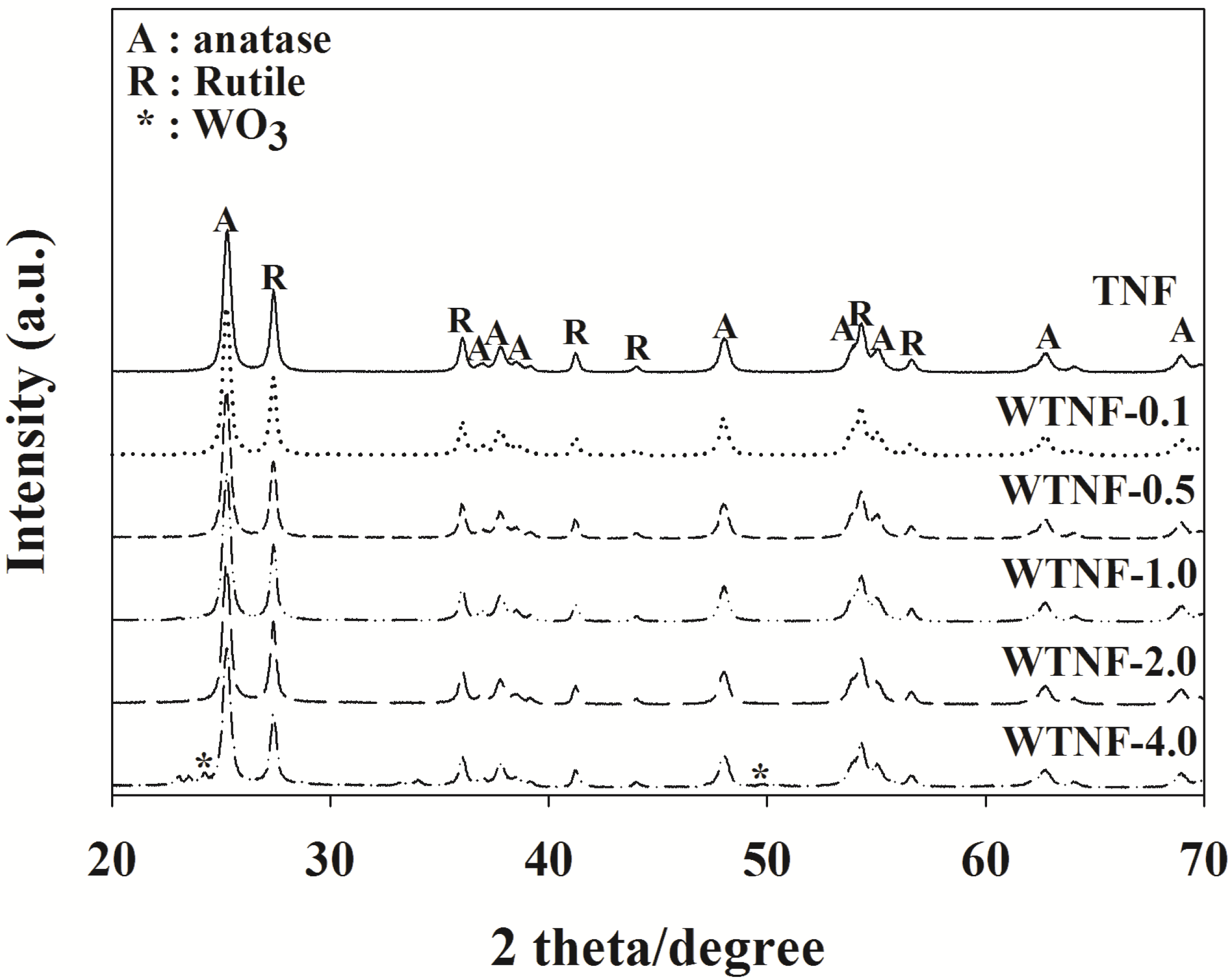
Figure 2.
Energy-dispersive X-ray spectroscopy of pure TiO2 nanoflowers (TNF) and WO3‒TiO2 nanoflowers with different WO3 loadings (WTNF-0.1, WTNF-0.5, WTNF-1.0, WTNF-2.0, and WTNF-4.0).
Figure 2.
Energy-dispersive X-ray spectroscopy of pure TiO2 nanoflowers (TNF) and WO3‒TiO2 nanoflowers with different WO3 loadings (WTNF-0.1, WTNF-0.5, WTNF-1.0, WTNF-2.0, and WTNF-4.0).

Figure 3.
Scanning electron microscopy of pure TiO2 nanoflowers (TNF) and WO3‒TiO2 nanoflowers with different WO3 loadings (WTNF-0.1, WTNF-0.5, WTNF-1.0, WTNF-2.0, and WTNF-4.0).
Figure 3.
Scanning electron microscopy of pure TiO2 nanoflowers (TNF) and WO3‒TiO2 nanoflowers with different WO3 loadings (WTNF-0.1, WTNF-0.5, WTNF-1.0, WTNF-2.0, and WTNF-4.0).

Figure 4.
UV-visible spectra of pure TiO2 nanoflowers (TNF) and WO3‒TiO2 nanoflowers with different WO3 loadings (WTNF-0.1, WTNF-0.5, WTNF-1.0, WTNF-2.0, and WTNF-4.0).
Figure 4.
UV-visible spectra of pure TiO2 nanoflowers (TNF) and WO3‒TiO2 nanoflowers with different WO3 loadings (WTNF-0.1, WTNF-0.5, WTNF-1.0, WTNF-2.0, and WTNF-4.0).

Figure 5.
Photocatalytic degradation efficiencies (PDE, %) of (a) toluene and (b) o-xylene as determined using pure TiO2 nanoflowers (TNF) and WO3‒TiO2 nanoflowers with different WO3 loadings (WTNF-0.1, WTNF-0.5, WTNF-1.0, WTNF-2.0, and WTNF-4.0).
Figure 5.
Photocatalytic degradation efficiencies (PDE, %) of (a) toluene and (b) o-xylene as determined using pure TiO2 nanoflowers (TNF) and WO3‒TiO2 nanoflowers with different WO3 loadings (WTNF-0.1, WTNF-0.5, WTNF-1.0, WTNF-2.0, and WTNF-4.0).

Figure 6.
Photoluminescence emission spectroscopy of pure TiO2 nanoflowers (TNF) and WO3‒TiO2 nanoflowers with different WO3 loadings (WTNF-0.1, WTNF-0.5, WTNF-1.0, WTNF-2.0, and WTNF-4.0).
Figure 6.
Photoluminescence emission spectroscopy of pure TiO2 nanoflowers (TNF) and WO3‒TiO2 nanoflowers with different WO3 loadings (WTNF-0.1, WTNF-0.5, WTNF-1.0, WTNF-2.0, and WTNF-4.0).

Figure 7.
Photocatalytic degradation efficiencies (PDE, %) of (a) toluene and (b) o-xylene as determined using WTNF-1.0 according to NaOH concentration.
Figure 7.
Photocatalytic degradation efficiencies (PDE, %) of (a) toluene and (b) o-xylene as determined using WTNF-1.0 according to NaOH concentration.
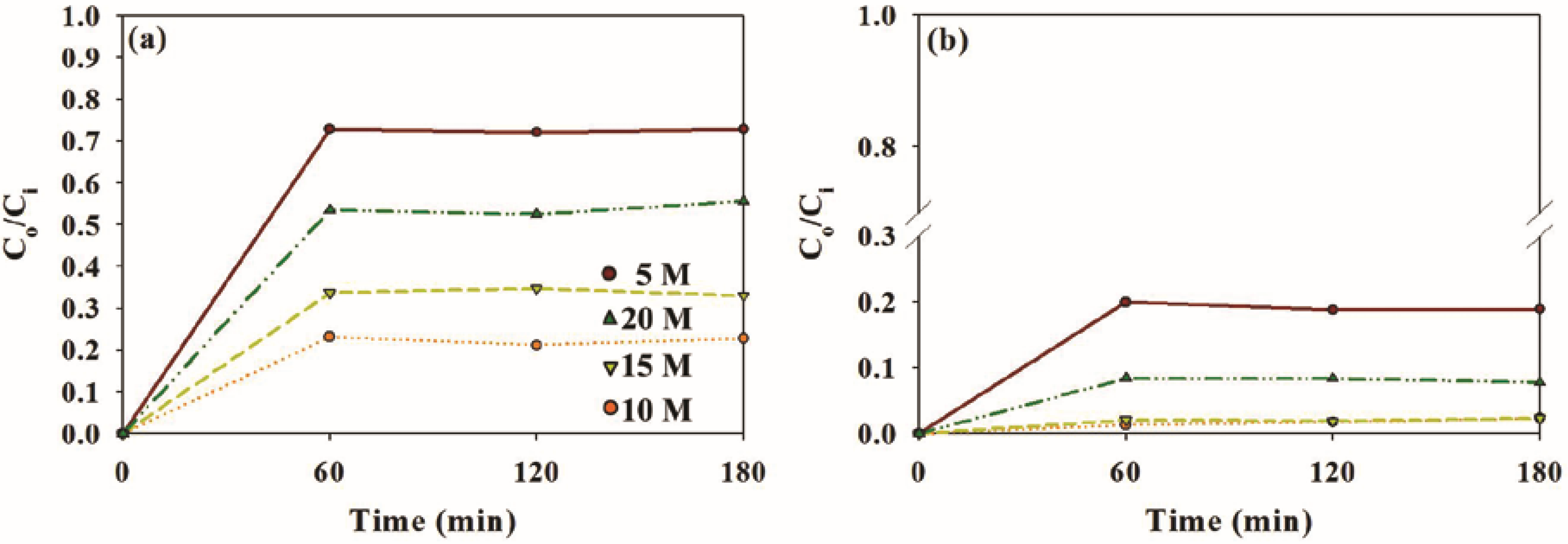
Figure 8.
Photocatalytic degradation efficiencies (PDE, %) of (a) toluene and (b) o-xylene as determined using WTNF-1.0 according to light source (conventional daylight lamp and white and violet LEDs).
Figure 8.
Photocatalytic degradation efficiencies (PDE, %) of (a) toluene and (b) o-xylene as determined using WTNF-1.0 according to light source (conventional daylight lamp and white and violet LEDs).
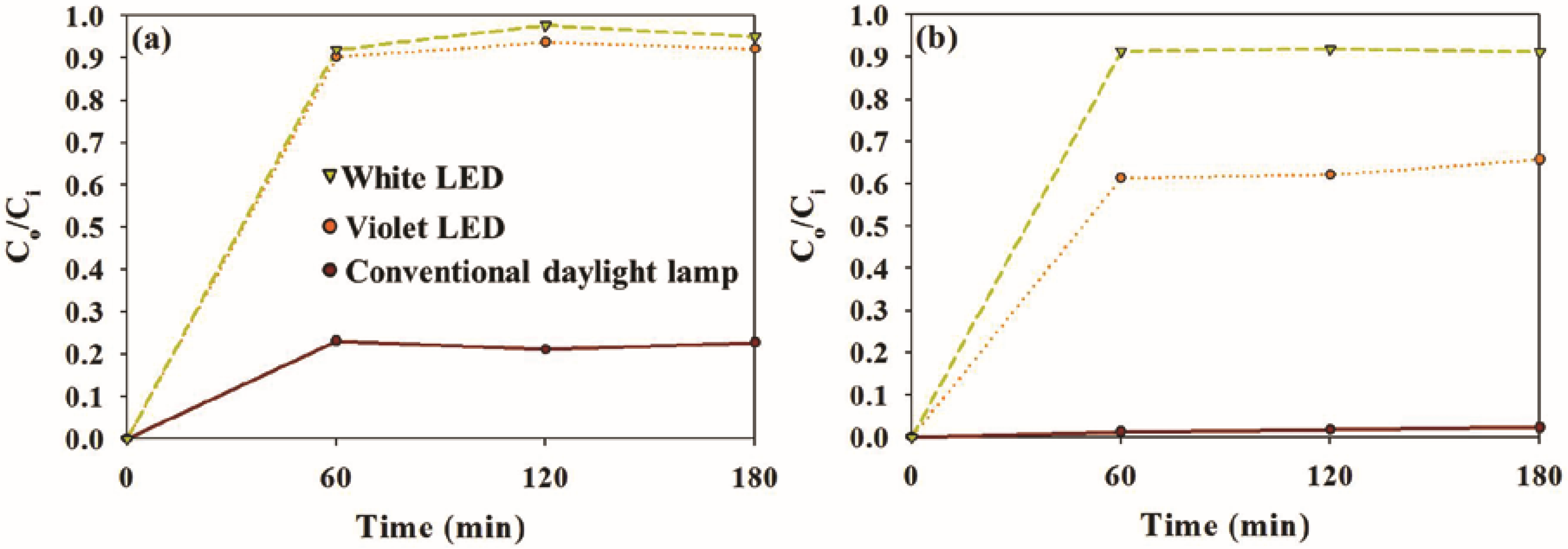
Figure 9.
Schematic diagram of experimental setup; 1: air cylinder; 2: rotameter; 3: water bath; 4: heated chamber; 5: syringe pump; 6: 3-way valve; 7: photocatalytic reactor with a conventional lamp; 8: photocatalytic reactor with LEDs.
Figure 9.
Schematic diagram of experimental setup; 1: air cylinder; 2: rotameter; 3: water bath; 4: heated chamber; 5: syringe pump; 6: 3-way valve; 7: photocatalytic reactor with a conventional lamp; 8: photocatalytic reactor with LEDs.

Table 1.
Properties of pure TiO2 nanoflowers (TNF) and WO3‒TiO2 nanoflowers with different WO3 loadings (WTNF-0.1, WTNF-0.5, WTNF-1.0, WTNF-2.0, and WTNF-4.0).
Table 1.
Properties of pure TiO2 nanoflowers (TNF) and WO3‒TiO2 nanoflowers with different WO3 loadings (WTNF-0.1, WTNF-0.5, WTNF-1.0, WTNF-2.0, and WTNF-4.0).
| Photocatalyst | SBET, m2 g−1 | Total Pore Volume, cm3 g−1 | Band Gap, eV |
|---|---|---|---|
| TNF | 102.1 | 0.30 | 3.30 |
| WTNF-0.1 | 122.6 | 0.37 | 2.97 |
| WTNF-0.5 | 133.4 | 0.31 | 2.96 |
| WTNF-1.0 | 135.4 | 0.36 | 2.96 |
| WTNF-2.0 | 107.4 | 0.25 | 2.95 |
| WTNF-4.0 | 104.8 | 0.22 | 2.92 |
© 2017 by the authors. Licensee MDPI, Basel, Switzerland. This article is an open access article distributed under the terms and conditions of the Creative Commons Attribution (CC BY) license (http://creativecommons.org/licenses/by/4.0/).
Share and Cite
MDPI and ACS Style
Lee, J.Y.; Jo, W.-K. Three-Dimensional TiO2 Structures Incorporated with Tungsten Oxide for Treatment of Toxic Aromatic Volatile Compounds. Catalysts 2017, 7, 97. https://doi.org/10.3390/catal7040097
AMA Style
Lee JY, Jo W-K. Three-Dimensional TiO2 Structures Incorporated with Tungsten Oxide for Treatment of Toxic Aromatic Volatile Compounds. Catalysts. 2017; 7(4):97. https://doi.org/10.3390/catal7040097
Chicago/Turabian StyleLee, Joon Yeob, and Wan-Kuen Jo. 2017. "Three-Dimensional TiO2 Structures Incorporated with Tungsten Oxide for Treatment of Toxic Aromatic Volatile Compounds" Catalysts 7, no. 4: 97. https://doi.org/10.3390/catal7040097
Note that from the first issue of 2016, this journal uses article numbers instead of page numbers. See further details here.