1. Introduction
Hydrogen energy, as a renewable energy source with high energy density, has garnered significant global attention in recent years [
1,
2,
3,
4,
5,
6]. Based on the analysis of the International Energy Agency (IEA) on the total global final energy consumption, the proportion of hydrogen energy in the total final energy consumption should increase to ~2% by 2030 and ~10% by 2050 [
7]. The coupling of renewable energy electricity with water electrolysis devices represents an effective means of producing green hydrogen [
8,
9,
10,
11]. However, due to the complex four-electron process involved in the oxygen evolution reaction (OER), which exhibits unfavorable reaction kinetics and high overpotentials, numerous researchers have focused on developing highly active OER catalytic electrodes [
12,
13,
14,
15].
Noble metal based OER catalysts, such as IrO
2 and RuO
2 [
16,
17,
18], demonstrate high activity but are limited by their exorbitant cost, finite reserves, and stability issues, hindering their large-scale application. Abundant non-noble metals such as Ni [
19,
20,
21], Co [
22,
23,
24], and Fe [
25,
26,
27] based compounds, including oxides, hydroxides, oxyhydroxides, and layered double hydroxides (LDHs), have shown promise as OER catalysts. As water electrolysis has already achieved industrialization and is witnessing rapidly growing demand, the capacity of individual alkaline water electrolysis devices has reached over 5 GW, with electrode sizes typically exceeding 2 m. Industrial electrodes are commonly produced using plasma spraying methods, where Raney nickel is applied to the cathode substrate surface, while the anode is typically produced via alloy powder spraying due to its feasibility for large-scale, low-cost manufacturing. Consequently, current research on water electrolysis catalytic electrodes should emphasize simplicity in synthesis methods and adaptability to large-scale. Lu et al. [
28] reported the application of a Cu
2S@NiS@Ni/NiMo electrocatalyst on a large-scale (100 cm
2) copper foam using a convenient scaling-up method. This electrode exhibited a low hydrogen evolution overpotential of 250 mV at 1000 mA cm
−2 and stable operation exceeding 2000 h at 500 mA cm
−2. However, research on large-scale, high-activity water electrolysis anodes remains insufficient.
NiFe-LDHs [
29,
30,
31] are widely recognized in the scientific community as excellent catalysts for the OER, playing a crucial role in energy conversion and storage systems. However, their performance at high current densities remains a challenge. To address this issue, Sun et al. [
32] took an innovative approach by growing NiFe-LDHs directly in situ as nanosheet arrays on Ni foam. This was achieved by placing the Ni foam substrate in an autoclave, allowing for the controlled growth of the nanosheet arrays. Similarly, Duan et al. [
33] employed an electrodeposition technique to grow LDH nanosheet arrays on Ni foam. Both methods aim to enhance the OER activity of NiFe-LDHs at high current densities by modifying their nanostructures. The nanosheet arrays, with their unique structure, reduce bubble size during the evolution of gas at the electrode surface. This reduction in bubble size lowers the mass transfer resistance, resulting in lower overpotentials at high current densities. These improved performance characteristics make them more suitable for industrial applications where high current densities and low overpotentials are essential. However, they also present challenges in terms of energy consumption and equipment requirements while these methods show promise in terms of enhancing OER activity. The autoclave and electrodeposition processes can be energy-intensive and require specialized equipment, posing significant obstacles to large-scale, cost-effective production.
In this work, we used commercially available Raney Ni-coated Ni mesh as a precursor to synthesize a large-scale water electrolysis anode NiFe(OH)x@Raney Ni exceeding 300 mm by simple immersion in a solution containing Ni(NO3)2 and Fe(NO3)3 at 60 °C. The prepared electrode exhibited an overpotential of only 240 mV at a current density of 10 mA cm−2, comparable to that of hydrothermally synthesized NiFe-LDHs. It also demonstrated stable operation exceeding 100 h at 500 mA cm−2. The large-scale electrode showed consistent overpotentials across different regions, and when incorporated into an alkaline water electrolysis device, it achieved an average cell voltage of 1.80 V and a direct current hydrogen production energy consumption as low as 4.3 kWh/Nm3, demonstrating its viability for industrial applications.
2. Results
The synthesis of NiFe(OH)
x@Raney Ni is achieved through a simple two-step immersion method (
Figure 1a). Initially, the Raney Ni-coated Ni mesh is thoroughly cleaned and then immersed in a solution containing 30 mM Ni(NO
3)
2 and 10 mM Fe(NO
3)
3 at 60 °C for 12 h. During this process, due to the presence of Al in Raney Ni and the protons resulting from the hydrolysis of metal nitrate solutions, a slow dissolution of Al occurs, releasing H
2. This leads to a local increase in pH, accompanied by the gradual reaction of Ni
2+ and Fe
3+ with OH
- to form NiFe(OH)
x. However, the amount of Al dissolved in this step is minimal. After the immersion, the electrode is placed in a 2 M KOH solution to dissolve the remaining Al and activate it, following the same procedure as the activation of commercial Raney Ni. The appearance of the electrode changes (
Figure 1b) from the original silver color to a brownish-yellow hue during immersion, indicating the successful synthesis of NiFe(OH)
x, as confirmed by the consistent color after Al dissolution and activation in the alkaline solution. In comparison, the Ni mesh without Raney Ni coating exhibits minimal color change after immersion under the same conditions (
Figure S1). Scanning Electron Microscopy (SEM) reveals that the original Raney Ni coating consists of uneven spherical particles (
Figure 1c). After immersion in the solution containing Ni
2+ and Fe
3+, nanosheet structures grow on the surface (
Figure 1d). Following Al dissolution and activation, the surface becomes more porous while maintaining the nanosheet structures (
Figure 1e,f). Energy-Dispersive X-ray Spectroscopy (EDS) elemental mapping of NiFe(OH)
x@Raney Ni (
Figure 1g) shows uniform distribution of Ni, Fe, and Al elements across the electrode surface. Notably, Al does not completely dissolve in Raney Ni, which aligns with previous applications. Specifically, regarding the remaining Al, we have demonstrated through EDS characterization that the atomic ratio in the material are as follows: Ni is 55.59%, Fe is 23.83%, and Al is 20.59% (
Supplementary Material Table S1). Specifically, the atomic ratio of Al in commercially activated Raney Ni is approximately 33%. The remaining Al in the NiAl phase can help maintain this porous structure, providing structural and thermal stability to the catalyst.
A detailed structural characterization of NiFe(OH)
x@Raney Ni was conducted. X-ray diffraction (XRD) patterns were compared for the prepared electrode before and after Al dissolution (
Figure 2a). It can be observed that with the dissolution of Al, the characteristic (111) diffraction peak at 2
θ = 38.47°, corresponding to PDF#04-0787 of Al, disappears. On the other hand, peaks located at 2
θ = 44.5°, 51.8°, and 76.4° correspond to the (111), (200), and (220) crystal planes of Ni (PDF#04-0850), respectively. Notably, the diffraction peak of the Ni (111) crystal plane shifts towards a lower angle with the dissolution of Al. Two small diffraction peaks can also be observed at 43.69° and 76.81°, corresponding to the (111) and (202) planes of AlNi
3 (PDF#21-0008), respectively. There was no significant change before and after activation, confirming the existence of AlNi
3 (Raney Ni), which is consistent with the results obtained through EDS-Mapping. The relatively small diffraction peaks are attributed to the fact that Raney Ni is located beneath the NiFe(OH)
x layer. The crystalline phase of elemental Al disappears after activation, but the crystalline phase of AlNi
3 remains present. This plays a crucial role in maintaining the porous structure of Raney Ni. Additionally, we have identified two characteristic peaks at 12.40° and 21.45°, which correspond to the NiFe compound (PDF#44-1088). X-ray photoelectron spectroscopy (XPS) was employed to analyze the electronic structure of NiFe(OH)
x@Raney. The high-resolution spectrum of Ni 2p (
Figure 2b) exhibits peaks at 856.03 eV and 873.98 eV, corresponding to Ni 2p3/2 and 2p1/2, respectively, confirming the presence of Ni
2+ in the sample [
34]. The peaks at 861.98 eV and 880.13 eV are accompanying satellite peaks. In the high-resolution spectrum of Fe 2p (
Figure 2c), peaks located at 711.08 eV and 724.73 eV correspond to 2p3/2 and 2p1/2, respectively, indicating that Fe exists in the form of Fe
3+ on the electrode surface [
35]. The peaks at 718.78 eV and 731.68 eV are satellite peaks of 2p3/2 and 2p1/2, respectively. In the high-resolution spectrum of Al 2p (
Figure 2d), the peak at 74.08 eV confirms the presence of Al
3+ [
36], while the peak at 68.38 eV is attributed to the Ni 3p signal, further supporting the existence of Ni
2+. In the O 1s high-resolution spectrum (
Figure S2), two peaks are present at 531.38 eV and 529.83 eV, corresponding to the OH signal from adsorbed H
2O and the metal-oxygen signal on the electrode surface [
37], respectively.
The OER activity of NiFe(OH)
x@Raney Ni was evaluated using the Cyclic Voltammetry (CV) curves obtained from a three-electrode system (
Figure 3a). The as-prepared electrode exhibited an overpotential of only 240 mV@10 mA cm
−2 and 401 mV@200 mA cm
−2. For comparison, the NiFe-LDHs@Ni mesh synthesized hydrothermally on the Ni mesh surface and the bare Ni mesh showed overpotentials of 241 mV@10 mA cm
−2 and 408 mV@200 mA cm
−2, respectively (
Figure 3b). We also compared the OER activity of Raney Ni@Ni mesh and bare Ni mesh. The overpotential of Raney Ni@Ni mesh was found to be 308 mV@10 mA cm
−2 and 503 mV@200 mA cm
−2, whereas the bare Ni mesh exhibited an overpotential of 340 mV@10 mA cm
−2 and 570 mV@200 mA cm
−2. All the performance test curves mentioned above have been IR correction, and the R
Ω value was determined from the EIS curve (
Figure S3). These results demonstrate the superior activity of the NiFe(OH)
x@Raney Ni electrode, which performs comparably to the hydrothermally synthesized NiFe-LDHs@Ni mesh and exhibits a more pronounced advantage in overpotential at higher current densities. This enhanced performance may be attributed to the smaller nanosheet size and lower mass transfer resistance of the prepared electrode compared to the hydrothermally synthesized electrode. We further analyzed the reaction kinetics of different electrodes through Tafel curves (
Figure 3c). The prepared NiFe(OH)
x@Raney Ni electrode (40.7 mV dec
−1) and NiFe-LDHs@Ni mesh (40.8 mV dec
−1) exhibited similar Tafel slopes, both lower than those of Raney Ni@Ni mesh (58.5 mV dec
−1) and Ni mesh (69.5 mV dec
−1). This confirms that the prepared electrode possesses excellent reaction kinetics, similar to those of the hydrothermally synthesized NiFe-LDHs@Ni mesh, which is consistent with their activity test results. Similar to previous reports, the high activity of the prepared catalyst is associated with the synergistic effect between Ni and Fe, and the strong Ni/Fe-O covalency facilitates electron transfer [
38]. To verify the stability of the electrode, chronopotentiometry curves were measured in a three-electrode system using 1 M KOH electrolyte (
Figure 3d). The electrode exhibited stable operation for over 240 h at current densities of 500 mA cm
−2. SEM characterization of the electrode after OER revealed that the nanosheet array structure on the electrode surface was maintained, confirming its high stability. Subsequently, detailed XPS characterization was performed on the electrode after the stability test (
Figure S4) to investigate changes in the electronic structure of the electrode surface. Comparison of the high-resolution XPS spectra for Ni before and after OER showed that the main peak of 2p3/2 shifted from 856.03 eV to 856.18 eV, indicating an increase in the Ni valence state. On the contrary, the main peak of 2p3/2 in the high-resolution spectrum of Fe shifted from 711.08 eV to 710.78 eV, suggesting a decrease in the Fe valence state. These observations are consistent with previous comparisons made for NiFe-LDHs before and after operation, where an increase in the Ni valence state is favorable for the formation of the OER active species NiOOH [
39]. On the other hand, the absence of any shift in the peak of Al 2p confirmed the stability of valence state of Al and indicated that there was no significant further dissolution.
Due to the simplicity and low cost of the preparation method, we successfully synthesized a large-scale NiFe(OH)
x@Raney Ni electrode exceeding 300 mm using a larger container and the same experimental approach (
Figure 4a). The electrode exhibited a relatively uniform surface color. To further verify the uniformity of the large-scale electrode’s performance, we selected five areas on its surface and conducted LSV curve tests for OER performance using a three-electrode system (
Figure 4b). The curves showed a high degree of overlap. Further analysis revealed that the overpotentials at a current density of 10 mA cm
−2 for the five regions were 249 mV, 247 mV, 245 mV, 248 mV, and 247 mV, respectively (
Figure 4c), demonstrating the successful synthesis of a highly uniform large-scale electrode. Subsequently, an electrolyzer containing two cells was assembled using the prepared electrode as the anode and a commercial Raney Ni electrode as the cathode (
Figure 4d). In particular, the anode we used in the electrolyzer was a circular electrode with a diameter of 115 mm, which was obtained by laser-cutting the aforementioned large-area electrode (
Figure S5). Each cell of the electrolyzer comprised a cathode, an anode, a bipolar plate, sealing gaskets, and a membrane (Zirfon UTP500, AGFA, Mortsel, Belgium). The assembled electrolyzer was integrated with a gas–liquid separator, temperature controller, and electrolyte circulation pump to form an alkaline water electrolysis device for evaluating the electrode’s performance. Constant current tests were conducted on the device at 80 °C and a current density of 200 mA cm
−2 using a 30% KOH electrolyte. The results showed that the electrode could operate stably for over 100 h. During the tests, the average cell voltage of the electrolyzer was 1.8 V, corresponding to a hydrogen production energy consumption of 4.3 kWh/Nm³, which is among the best-performing commercial alkaline electrolyzers. In addition, we used the drainage method to test the Faraday efficiency of H
2 and O
2 under different current densities in 50 s. In electrolyzer testing, the theoretical gas production is relatively large (197.25 mL of H
2 produced under electrolysis at 150 mA cm
−2 for 50 s), which allows for a more accurate evaluation of Faraday efficiency. The data results are shown in
Table S2, where the Faraday efficiencies of H
2 and O
2 are 99.3% and 99.4, respectively. Overall, the simple synthesis method and high activity of the NiFe(OH)
x@Raney Ni electrode make it a promising candidate for industrial applications.
3. Material and Methods
3.1. Chemicals
All reagents employed in this study were of analytical grade and utilized as-is, without any need for further purification processes. Ni(NO3)2·6H2O, Fe(NO3)3·9H2O, KOH, CO(NH2)2, and C2H5OH were purchased from Shanghai Aladdin Biochemical Technology Co., Ltd., Shanghai, China. Ni mesh and Raney Ni-coated Ni mesh were purchased from Zhangjiakou Ruiqing Technology Co., Ltd., Zhangjiakou, Hebei Province, China. Deionized water was purchased from Hangzhou Wahaha Co., Ltd., Hangzhou, Zhejiang Province, China.
3.2. Synthesis of NiFe(OH)x@Raney Ni
In the initial phase of the experiment, small pieces measuring 1 cm × 2 cm were excised from a monolithic Raney Ni-coated Ni mesh. This step was essential to ensure uniformity and controllability in the dimensions of the electrode material for subsequent experimental procedures. Following excision, these pieces were submerged in ethanol and subjected to ultrasonic cleaning, an effective method for eliminating surface impurities and contaminants, thereby ensuring the purity and homogeneity of the electrodes. The material underwent ultrasonic cleaning in ethanol for a duration of 15 min. After the cleaning process, the Raney Ni-coated Ni mesh pieces were removed from the ethanol and placed in a drying oven maintained at 60 °C to eliminate any residual ethanol on the surface and prepare them for the subsequent impregnation step. Next, a solution containing 30 mM Ni(NO3)2·6H2O and 10 mM Fe(NO3)3·9H2O was prepared using deionized water, and 50 mL of this solution was dispensed into a beaker. This solution played a pivotal role in the subsequent impregnation process, providing the necessary nickel and iron ions for the synthesis of NiFe(OH)x. Subsequently, the pre-dried 1 cm × 2 cm Raney Ni-coated Ni mesh pieces were immersed in the aforementioned solution, ensuring complete submersion. Following impregnation, the beaker containing the solution and the mesh pieces was placed in a 60 °C oven for 12 h. This step aimed to facilitate the reaction between the material surface and the ions in the solution, leading to the formation of NiFe(OH)x. Finally, the electrodes were removed from the solution and rinsed with deionized water to eliminate any excess ions or unreacted substances adhering to the surface. After rinsing, the electrodes were once again placed in the oven for drying. The resulting dried electrodes constituted the desired NiFe(OH)x@Raney Ni electrodes. Throughout the entire preparation process, parameters such as temperature, time, and solution concentration were rigorously controlled to ensure the production of electrodes with optimal performance and reproducibility.
3.3. Synthesis of NiFeLDHs@Ni Mesh
Initially, the Ni mesh was precisely cut into small rectangular pieces measuring 1 cm × 2 cm, suitable for use as electrodes in subsequent experiments. To ensure the removal of any residual organic contaminants, such as oils or greases, from the surface of these electrode pieces, they were immersed in ethanol and subjected to ultrasonic cleaning for a duration of 15 min. This cleaning process effectively dislodged and removed the unwanted surface impurities. Following the ethanol treatment, the electrode pieces were carefully removed and placed in a drying oven to evaporate any residual solvent, ensuring a dry and clean surface for further processing. Next, to eliminate any oxide layer that might have formed on the surface of the Ni mesh during storage or handling, the pieces were transferred to a bath of concentrated hydrochloric acid. Here, they underwent a second ultrasonic cleaning step, lasting for 5 min. This acidic treatment was crucial in removing any oxides that could potentially interfere with subsequent reactions or affect the electrode’s performance. After the acid treatment, the electrode pieces were thoroughly rinsed with deionized water to remove any traces of acid or dissolved oxides. In preparation for the synthesis of the desired material, a solution containing the necessary precursors was prepared. Specifically, 35 mL of deionized water was measured into a clean beaker, and to this, precise amounts of Ni(NO3)2·6H2O (0.5 mmol), Fe(NO3)3·9H2O (0.5 mmol), and CO(NH2)2 (5 mmol) were added. These components were mixed and stirred vigorously to ensure complete dissolution and a homogeneous solution. Subsequently, the prepared solution, along with the pre-cleaned Ni mesh electrode pieces, was carefully transferred into a Teflon-lined autoclave. The Teflon lining provided a chemically inert environment, crucial for high-pressure and high-temperature reactions. The autoclave was then sealed and placed in an oven preheated to 120 °C. The reaction was allowed to proceed for 12 h under these controlled conditions, ensuring optimal growth and crystallization of the desired material on the electrode surface. After the reaction time elapsed, the autoclave was removed from the oven and allowed to cool to ambient temperature. The electrode pieces were then carefully retrieved from the reaction mixture and subjected to a final cleaning step. This involved ultrasonic cleaning in deionized water for 5 min to remove any loosely attached particles or impurities that did not grow in situ on the electrode surface during the synthesis process. The resulting product, NiFeLDHs@Ni mesh, exhibited the desired characteristics and was ready for further characterization or use in downstream applications. The entire process, from cutting and cleaning to synthesis and final cleaning, was carefully controlled to ensure reproducibility and consistency in the quality of the electrodes produced.
3.4. Electrochemical Measurements
The electrochemical measurements were executed under ambient conditions within a standardized three-electrode setup enclosed in a glass cell, which was interfaced with a sophisticated electrochemical workstation (specifically, the model CHI 660e from CH Instruments, Shanghai, China). The dimensions of the electrocatalysts were precisely maintained at 1 cm × 1 cm, and these catalysts were directly utilized as the working electrode without any further modifications or treatments. A carbon rod electrode, known for its stability and conductivity, served as the counter electrode in this configuration. Meanwhile, a saturated calomel electrode (SCE) is used to provide a reliable reference potential, ensuring the accuracy of potential measurements throughout the entire experimental process, with a standard electrode potential of ESCE = 0.244 V (vs. RHE). For the electrolyte, a freshly prepared 1 M KOH solution was utilized, offering a suitable alkaline environment for the electrochemical reactions under investigation. Additionally, the activation process of the catalyst was rigorously assessed through cyclic voltammetry (CV). This technique was performed at a scan rate of 100 mV s−1 for 20 consecutive cycles, spanning a potential range of 0 to 1 V versus the SCE in the aforementioned electrolyte. This comprehensive approach allowed for a thorough evaluation of the catalyst’s electrochemical behavior and activation characteristics. It is important to note that all measured potentials were referenced to the SCE and were subsequently converted to the reversible hydrogen electrode (RHE) scale using the Nernst equation (ERHE = ESCE + pH × 0.059). This conversion ensures compatibility and comparability with other electrochemical studies, facilitating a broader understanding of the system’s performance. Polarization curves, which provide valuable insights into the electrode’s performance under varying potential conditions, were obtained using Linear sweep voltammetry (LSV) with a scan rate of 5 mV s−1. These curves were carefully corrected for Ohmic drops, which were meticulously tested through impedance spectroscopy techniques. This correction is crucial as it accounts for the potential losses due to electrolyte resistance, ensuring accurate and reliable polarization data. Furthermore, electrochemical impedance spectroscopy (EIS) measurements were conducted in the 1 M KOH solution. These measurements involved applying an AC voltage with an amplitude of 5 mV at the open circuit potential, while sweeping the frequency from 100 kHz to 0.1 Hz. EIS provides valuable information on the electrode’s electrochemical behavior, particularly its charge transfer characteristics and interfacial reactions, further enhancing our understanding of the system’s performance and kinetics.
3.5. Materials Characterization
The specimens’ dimensions and microscopic structure were meticulously examined using a state-of-the-art field-emission scanning electron microscope (FE-SEM, model JEOL JSM6335, TEM, Tokyo, Japan). Operating at an accelerating voltage of 20 kV, this high-resolution instrument allowed for detailed visualization of the specimens’ surface features and microstructures. The FE-SEM analysis was crucial in revealing the specimens’ size, shape, and surface morphology, essential for understanding their material properties and potential applications. To further investigate the structural characteristics of the specimens, X-ray diffraction (XRD) measurements were performed. Utilizing a Rigaku D/max 2500 X-ray diffractometer (Tokyo, Japan) equipped with Cu Kα radiation, operating under conditions of 40 kV, 30 mA, and a wavelength (λ) of 1.5418 Å, the XRD patterns were obtained. These patterns provided valuable insights into the specimens’ crystalline structure, including phase identification, crystal orientation, and lattice parameters. The measurements were conducted over a 2θ angular range of 5° to 80°, with a scanning rate of 5° per minute, ensuring a comprehensive analysis of the specimens’ structural properties. In addition, to further understand the chemical composition of the sample, X-ray photoelectron spectroscopy (XPS) analysis was also performed, with a source gun type of Al Ka, excitation voltage of 15 kV, and lamp current of 10 mA. These analyses were carried out using a PHI Quantera II XPS Scanning Microprobe system (ULVAC-PHI, Inc., Chigasaki, Japan), a highly sensitive instrument capable of detecting the elemental composition and chemical states of the specimens’ surfaces. The XPS data provided critical information on the specimens’ elemental composition, oxidation states, and bonding configurations, essential for elucidating their chemical properties and potential reactivity. Collectively, these advanced analytical techniques—FE-SEM, XRD, and XPS—offered a comprehensive characterization of the specimens, revealing their size, shape, crystalline structure, and chemical composition. This detailed understanding of the specimens’ properties is crucial for further exploring their potential applications and optimizing their performance in various fields.
3.6. Performance Evaluation of Alkaline Water Electrolysis Devices
The alkaline water electrolysis devices testing system, sourced from Zhangjiakou Ruiqing Technology Co., Ltd., Zhangjiakou, China, is a comprehensive setup designed to evaluate the performance of alkaline water electrolysis under controlled conditions. This system integrates several key components, including an electrolyzer, gas–liquid separator, DC power supply, electrolyte circulation pump, and a precise temperature control system. The electrolyzer, a core element of the testing system, is configured with two cells, arranged in a manner that allows for efficient and controlled electrochemical reactions. A notable feature of this electrolyzer is the utilization of a composite membrane, specifically the AGFA ZIRFON UTP500, Mortsel, Belgium. Within the electrolytic cell configuration, the anode employs an electrode that was specifically synthesized in the course of this study. This customized electrode is designed to optimize the electrochemical reactions occurring at the anode, thereby enhancing the overall efficiency of the water electrolysis process. Conversely, the cathode is comprised of Raney Ni coated Ni mesh. The testing conditions were carefully controlled to simulate real operational scenarios. Specifically, the temperature was maintained at 80 °C, a temperature commonly employed in alkaline water electrolysis systems due to its favorable impact on electrolyte conductivity and reaction kinetics. Additionally, the electrolyte circulation rate was set at 6 L/min to ensure adequate mixing and heat transfer within the electrolyzer. In terms of data acquisition and analysis, the cell voltage is calculated as half of the total voltage measured across both cells. This calculation accounts for the fact that the electrolyzer operates with two cells in series. Furthermore, the DC energy consumption is determined by multiplying the cell voltage by a factor of 2.39, a coefficient that takes into account various system-specific parameters such as electrolyte resistivity and cell geometry.

 and
and 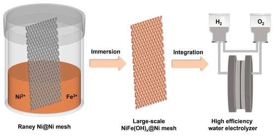


