Article

Store-Carry and Forward-Type M2M Communication Protocol Enabling Guide Robots to Work together and the Method of Identifying Malfunctioning Robots Using the Byzantine Algorithm

Information Systems Science Major, Graduate School of Engineering, Soka University, 1-236 Tangi-cho, Hachioji-shi 192-8577, Japan
*
Author to whom correspondence should be addressed.
Computers 2016, 5(4), 30; https://doi.org/10.3390/computers5040030
Submission received: 25 August 2016 / Revised: 14 November 2016 / Accepted: 21 November 2016 / Published: 28 November 2016

Abstract

:
This paper concerns a service in which multiple guide robots in an area display arrows to guide individual users to their destinations. It proposes a method of identifying malfunctioning robots and robots that give wrong directions to users. In this method, users’ mobile terminals and robots form a store-carry and forward-type M2M communication network, and a distributed cooperative protocol is used to enable robots to share information and identify malfunctioning robots using the Byzantine algorithm. The robots do not directly communicate with each other, but through users’ mobile terminals. We have introduced the concept of the quasi-synchronous number, so whether a certain robot is malfunctioning can be determined even when items of information held by all of the robots are not synchronized. Using simulation, we have evaluated the proposed method in terms of the rate of identifying malfunctioning robots, the rate of reaching the destination and the average length of time to reach the destination.

1. Introduction

Today, a variety of robots designed for different purposes is used to assist our lives [1,2,3,4,5,6]. Network robot platforms have been studied in order to enable service robots to provide services by working with sensors and appliances via a network rather than being standalone [7,8,9,10,11,12,13]. Such network robots can take the form of physical entities, software agents on appliances or sensors embedded in the surroundings. These three types of robot are respectively referred to as “visible robots”, “virtual robots” and “unconscious robots”. A major application of service robots is guide robots that provide direction guidance information to visitors to a shopping mall [10,11,12,13]. However, there has been no study on how to identify malfunctioning robots from among many collaborating robots.
In recent years, there has been a growing interest in machine-to-machine (M2M) communication. Systems are being studied that use interactions between machines via M2M communication to provide services to humans (end users) without requiring human intervention [14]. While M2M communication is expected to improve the efficiency, safety or comfort of a variety of business operations, it can also be used for inter-robot communication. M2M communication protocols that have been studied so far assume communication over the Internet or mobile communication networks, such as GSM, LTE, 4G or wireless LAN. No studies have been made on store-carry and forward-type communication protocols, which are used for near field communication with mobile users.
The present study concerns a service in which virtual guide robots (simply referred to as “robots”) and users’ mobile terminals work together using near field communication to guide individual users to their destinations. In this service, robots only display arrows to indicate the directions individual users should take. If a robot is defective or infected with a virus, it displays an incorrect direction. This paper proposes a method of identifying such malfunctioning robots. Specifically, information as to whether a certain robot is malfunctioning is transmitted using a distributed cooperative protocol based on store-carry and forward M2M communication, which relies on user mobility. The paper also proposes a method of identifying malfunctioning robots using the Byzantine algorithm. The robots do not directly communicate with each other, but exchange information via users’ mobile terminals. For the identification of malfunctioning robots, we have introduced the concept of the pseudo-synchronization number, which makes it possible to identify malfunctioning robots even when items of information in all of the robots are not synchronized. Using simulation, we have evaluated the effectiveness of the proposed method in terms of the rate of identifying malfunctioning robots, the rate of reaching the destination and the average length of time to reach the destination. This paper is structured as follows. Section 2 provides an overview of existing studies. Section 3 presents the proposed architecture for enabling multiple robots to work together. Section 4 proposes a method of identifying malfunctioning robots using the Byzantine algorithm. Section 5 describes the system used to evaluate the proposed method. Section 6 presents the evaluation results. Finally, Section 7 gives the conclusions and future issues.

2. Related Work

This section introduces existing studies on robot services and specific application environments in the areas assumed by our proposed method, such as a smart city. In addition, it presents existing studies on M2M systems and security and the position of this paper within the context of the existing studies.

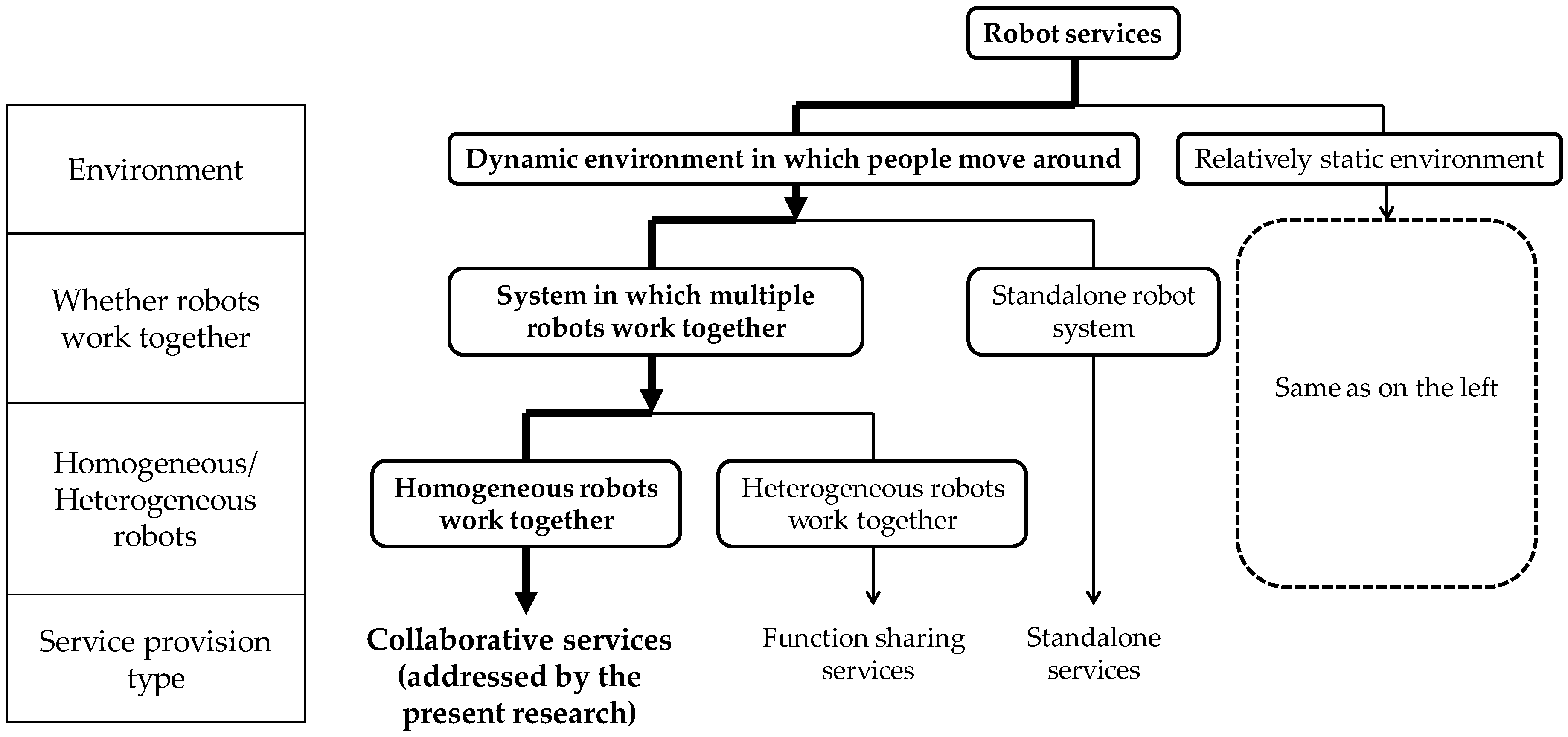
2.1. Network Robot Services

Communication robots have been studied as new devices that provide navigation or information services [7,8,9,10,11,12,13]. Examples of robots that mainly interact with a human on a one-on-one basis and provide a service in a relatively static environment include those that explain exhibits in museums [2,3], those that act as receptionists at university buildings [4], those that support language learning at elementary schools [5] and those that assist healthcare at the hospital or at home [6]. In addition, standalone robot systems that provide an information service in a dynamic environment where people move around, such as shopping malls [12], and networked robot systems, in which multiple robots work together [7,8,9,10,13], have been developed. There are two types of networked robot systems. In the first type, different robots play different roles (function sharing service). In the second type, all robots play the same role, are distributed within a given environment and work together to provide a service (collaborative service).
This paper focuses on a collaborative service. Since multiple robots that play the same role work together to provide a service, it is important to detect malfunctioning robots, robots whose behavior deviates from that of other robots. The classification of the robot services described above and the position of this paper are shown in Figure 1.

2.2. M2M Systems and Security

2.2.1. M2M Area Network

A framework for M2M systems is being standardized in ETSI [15]. Three types of M2M network are defined: M2M core network, M2M access network and M2M area network. The M2M area network supports networks on the device side. Two communication types are defined for this network. In the first type, the gateway and devices are connected in a star-shaped network. In the second type, devices communicate with each other directly. The latter communication is called D2D (device-to-device) communication. The M2M area network is designed with an emphasis on lowering power consumption by reducing the communication speed and distance. Communication systems used for this purpose are ZigBee, which supports PANs (personal area networks) designed for low-power networks, Bluetooth and wireless LANs, such as WiFi. However, ETSI’s framework does not cover the details of D2D communication.
The network being addressed by this paper falls in the category of D2D communication in an M2M area network. It is an inter-robot ad hoc network using users’ mobile terminals as conveyors of information. A store-carry and forward-type communication protocol is proposed for robot-to-robot (R2R) communication.

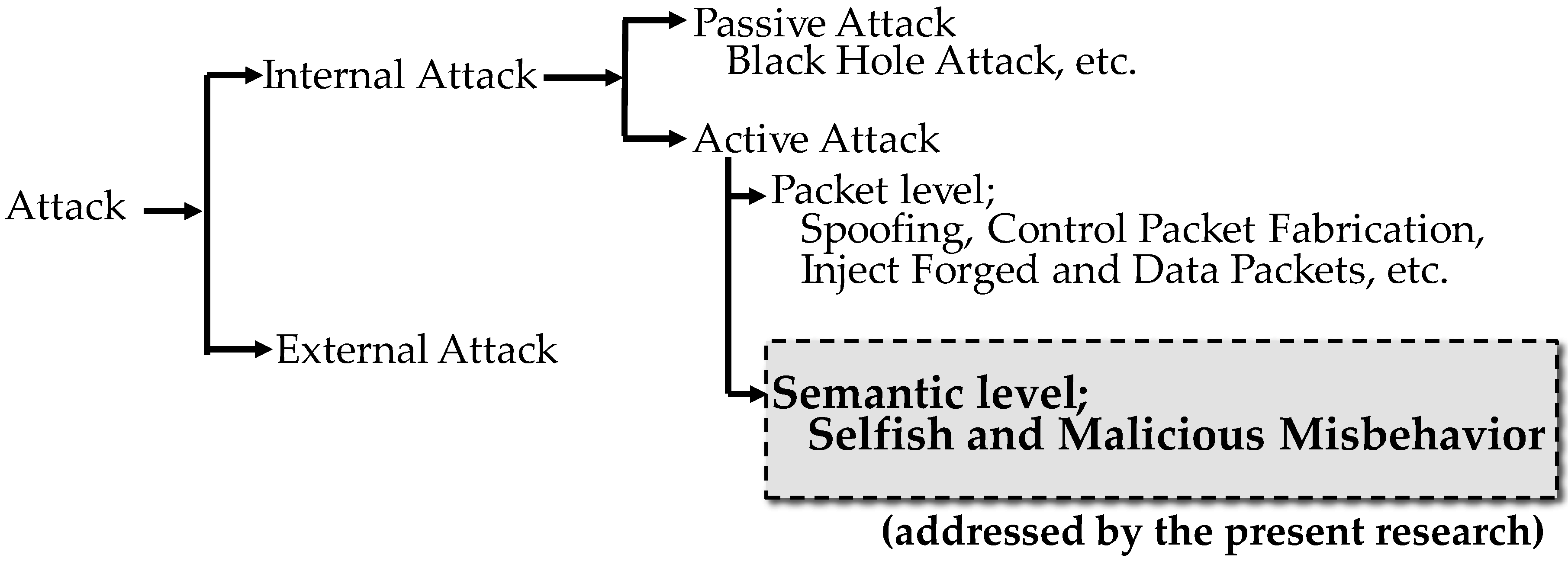
2.2.2. Security of M2M Area Networks

Just like the Internet, M2M area networks are subject to threats. Attacks may come from inside the M2M area network or from an external network. If the M2M area network is a D2D ad hoc network, it may be subject to passive or active attacks from malicious devices. An example of a passive attack is the black hole attack [16]. Active attacks can be classified into spoofing, falsification of control packets, excessive transmission of false packets and others at the packet level [17,18], as well as illegal operations at the application level.
The proposed M2M area network is a store-carry and forward-type R2R ad hoc communication network. Typical attacks on this network can be classified as shown in Figure 2. This paper proposes a method of detecting active attacks at the semantic level as shown in Figure 2.

3. Architecture for Enabling Robots to Work Together

This section presents the proposed architecture for enabling multiple robots to work together and a proposed angle-based direction guidance algorithm.

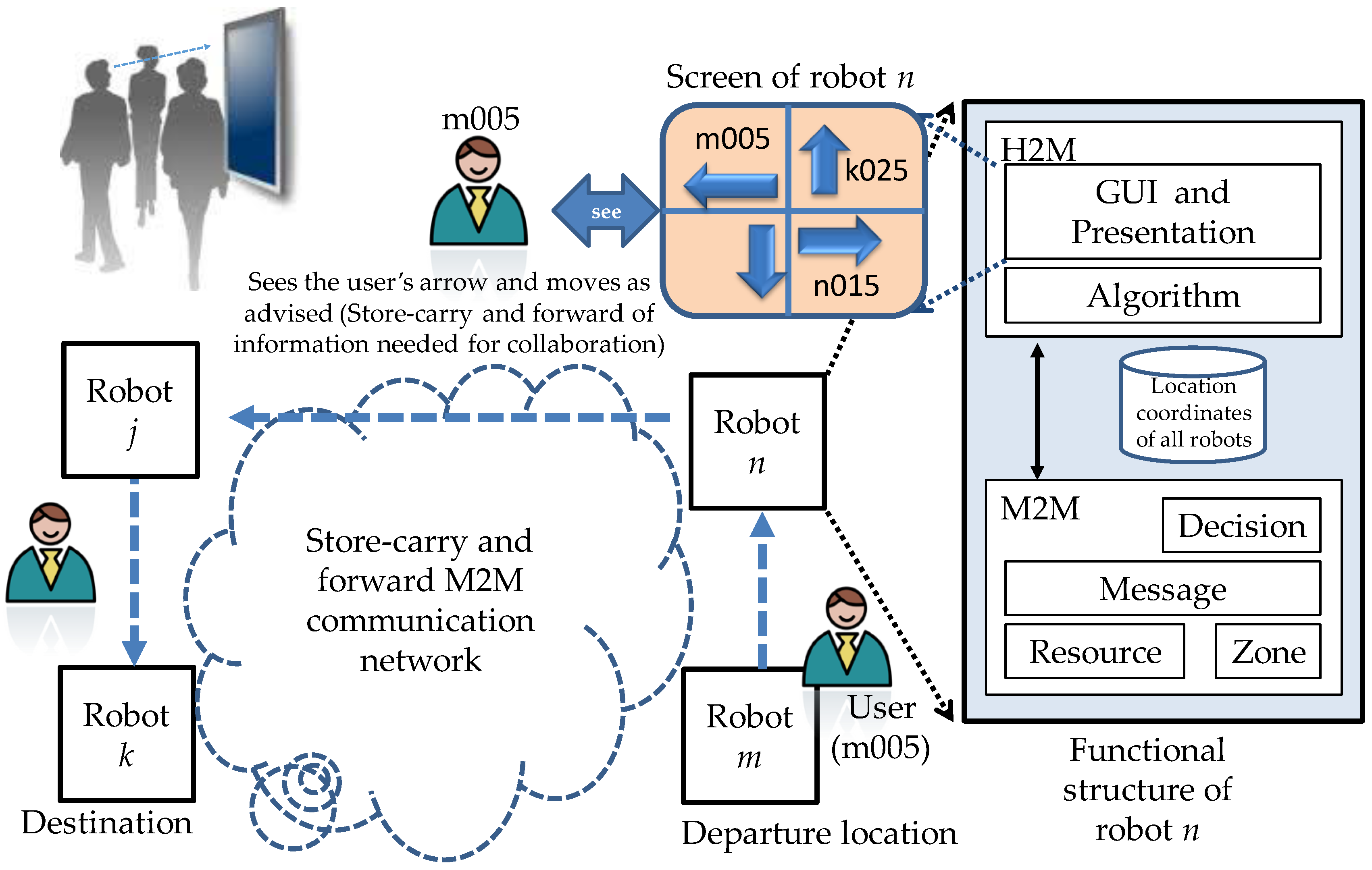
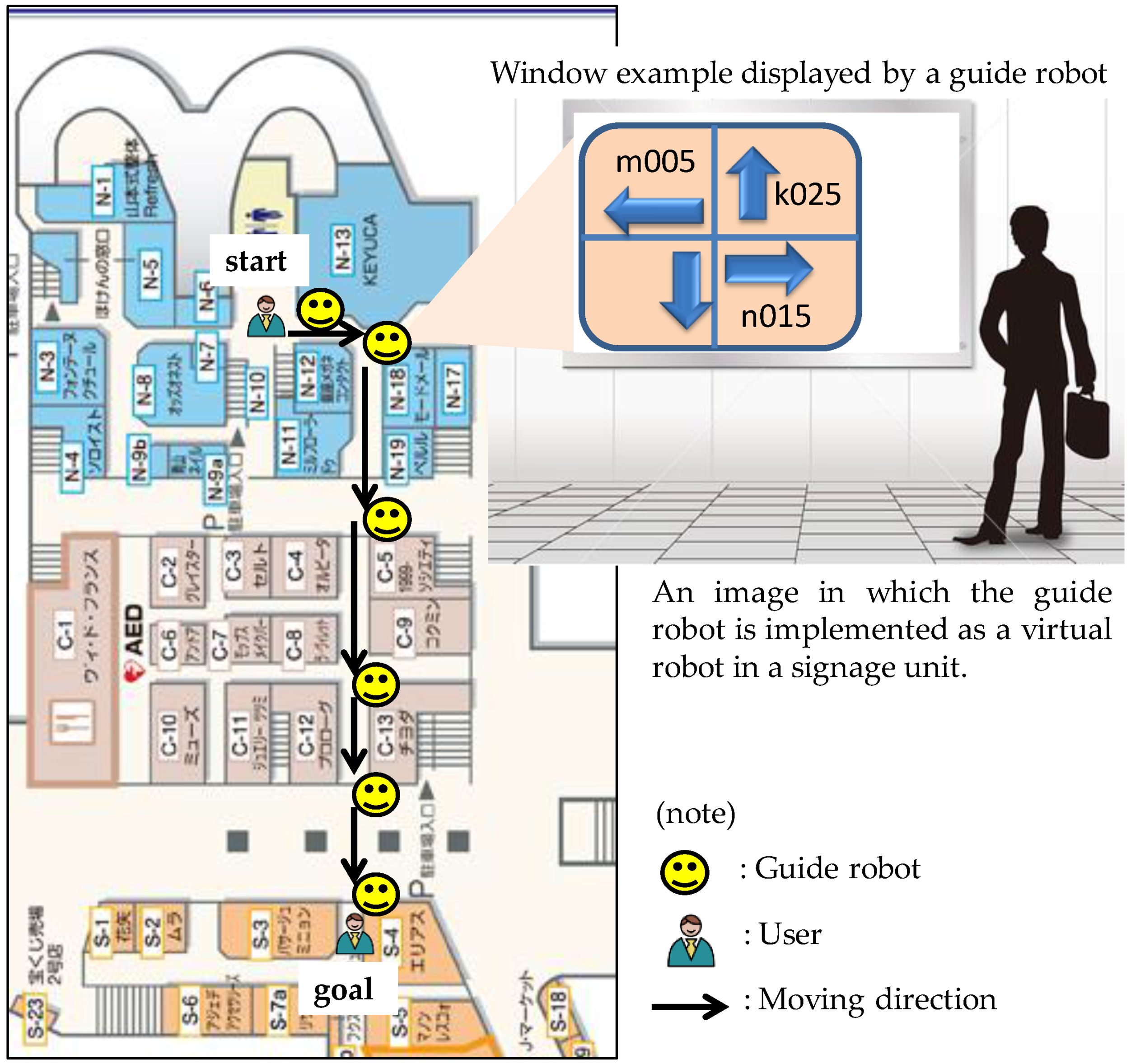
3.1. Overview of Direction Guidance and the Functional Structure

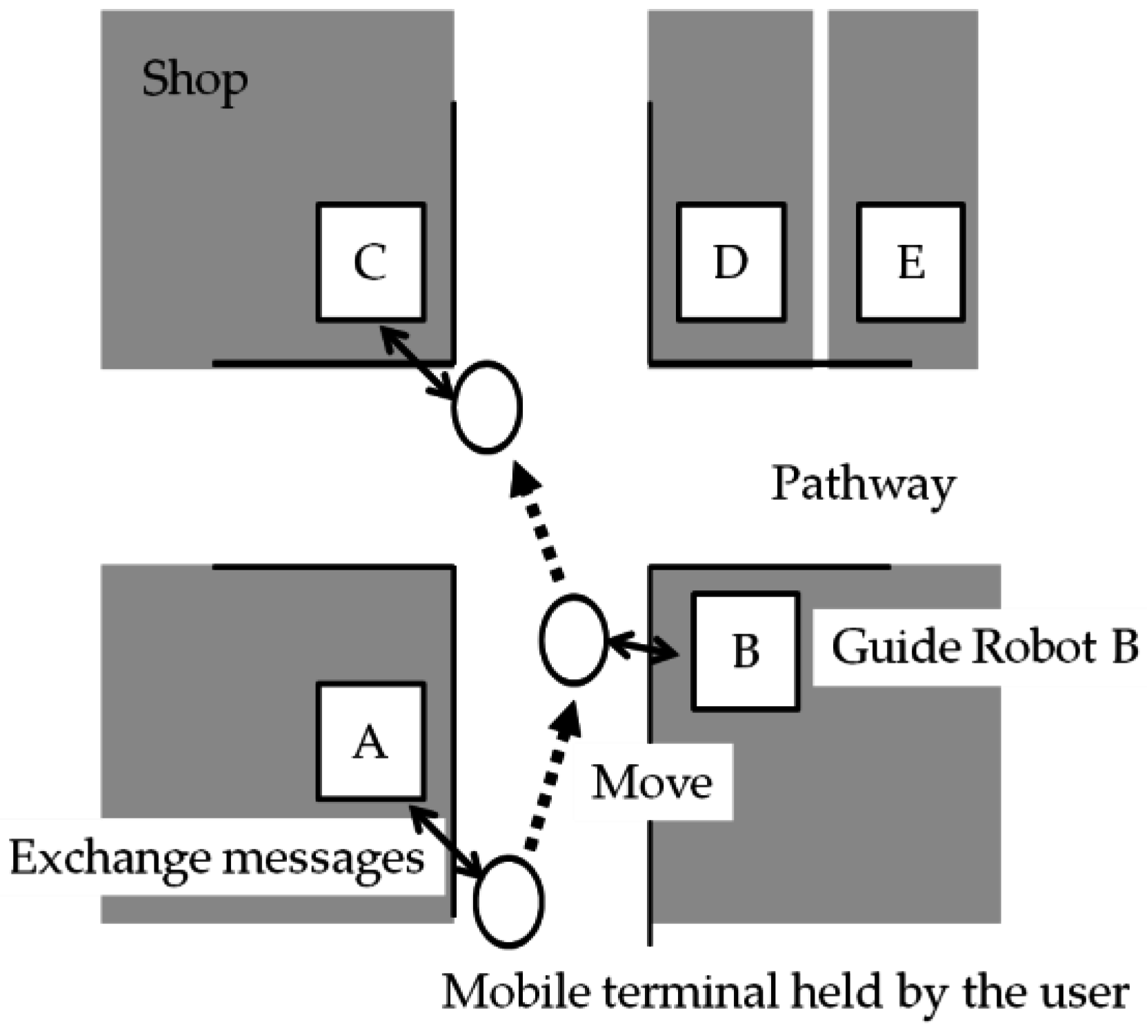
3.1.1. Overview of Direction Guidance

This paper assumes the following. Every user has a mobile terminal. These terminals communicate with robots using near field communication. Multiple robots exist in the area in question and work together to provide guidance to users. Each robot has information about the locations of all of the other robots. The robot near a user’s departure location assigns an identification number, which is unique within the area, to his or her mobile terminal. An identification number consists of the identifier of the robot and a sequential number. For example, if a mobile terminal is the fifth one that robot m communicates with, the identification number of this mobile terminal is m005. If the numerical part of an identification number exceeds 999, it is reset to 001. Any mobile terminal that starts communication with a new robot sends its identification number to the robot. This enables the robot to decide that this communication is intended for requesting guidance, thereby eliminating unnecessary communication. When a user comes near a robot, an arrow indicating the direction he or she should take is displayed on the robot’s screen. The user checks the identification numbers shown on the screen and moves in the direction of the arrow shown for the identification number of his or her mobile terminal. This is repeated until the user reaches his or her destination. The architecture for achieving navigation through collaboration of multiple robots as described above is shown in Figure 3. An example of navigation based on the floor map of an actual underground shopping mall [19] is shown in Figure 4. Guide robots are installed at the corners of the shops N-13, N-18, C-5, C-13 and S-4. Suppose that a user standing near N-13 wants to go to S-4. He or she looks for his or her identification number on the window displayed by the robot at N-13 and goes in the direction shown by the arrow that is associated with his or her identification number. He or she then finds an arrow displayed by the robot at N-18 and chooses his or her direction accordingly. By repeating this, he or she ultimately reaches S-4.

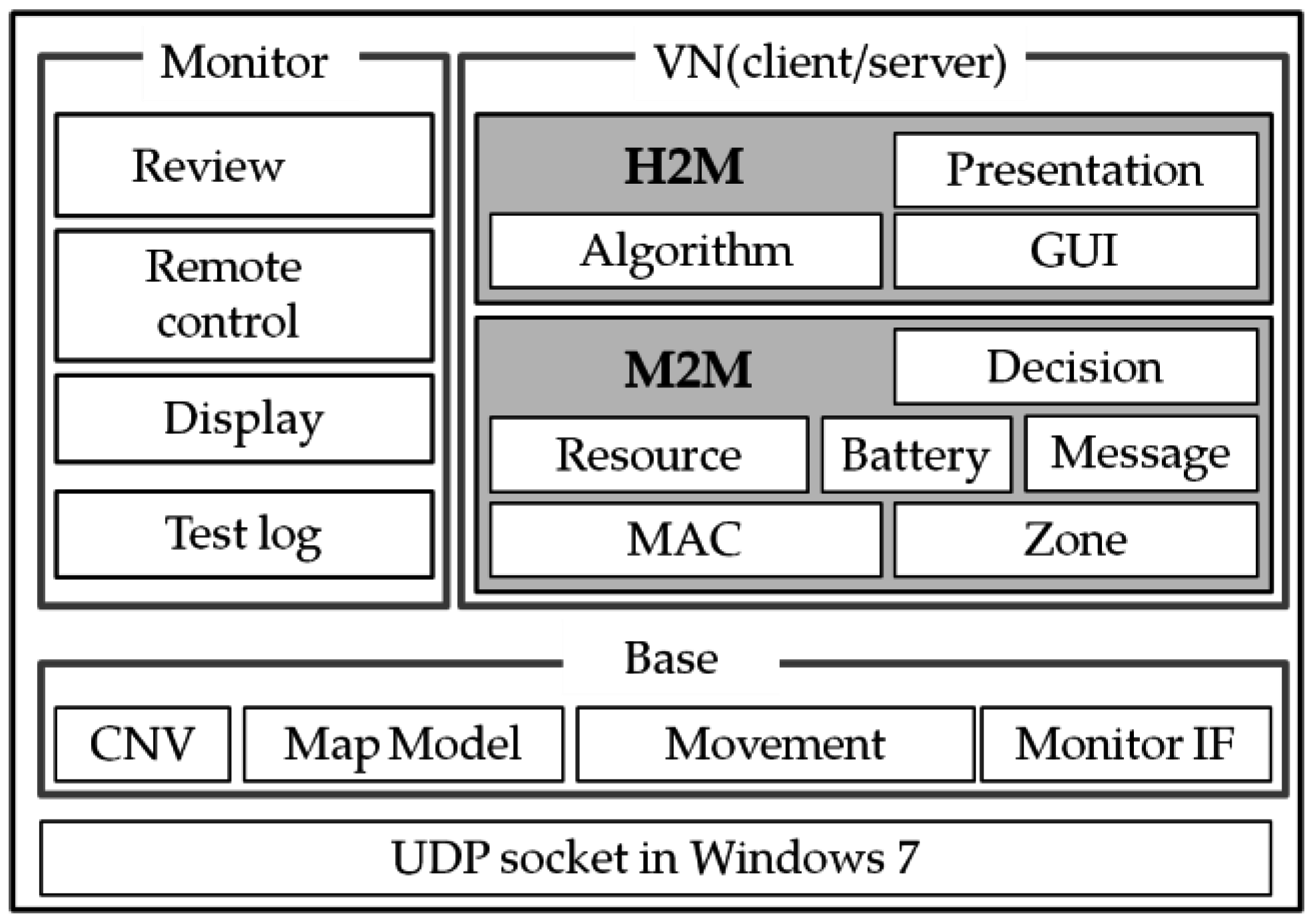
3.1.2. Functional Structure of a Robot

A robot mainly consists of an H2M (Human-to-Machine) function, an M2M function and a database that contains the location coordinates of all of the robots in the area.
The direction guidance algorithm described in Section 3.2 is implemented in the H2M function. This function provides a user interface used to control how to display arrows and identifiers (display location and display duration TD). The M2M function handles near field communication between robots and mobile terminals and communication between robots via mobile terminals. The distributed cooperative protocol using store-carry and forward-type M2M communication as proposed in Section 4.1 and the algorithm for identifying malfunctioning robots as proposed in Section 4.2 are implemented in this function. In places where users exist at a high density, a robot may simultaneously communicate with multiple mobile terminals. In order to prevent a robot from being congested in such a situation, a robot has a connection resource management function, which restricts the number of simultaneous connections using a table for managing the state of communication with each mobile terminal. Specifically, the number of simultaneous connections from mobile terminals to a robot is limited to NL in order to reduce each robot’s processing load for handling connection requests from mobile terminals. When a mobile terminal comes into the area covered by a robot that is already communicating with NL mobile terminals, the robot refuses to accept a connection request from this new mobile terminal.

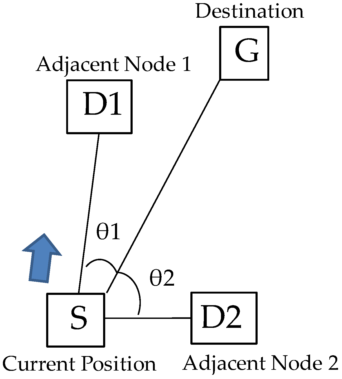
3.2. Guidance Based on the Angle-Based Algorithm

Guidance is provided based on a greedy algorithm, in which guidance is provided based on locally available information only. The authors have proposed this algorithm in [20]. This algorithm decides whether the user should go toward one adjacent node or toward another adjacent node based on the comparison between two angles: the angle between the line drawn from the user’s current location to the destination and the line drawn from the current location to the first adjacent node and the angle between the former line and the line drawn from the current location to the second adjacent node. This algorithm is described in detail below.
This angle-based algorithm is shown Figure 5. Let the angle between the line drawn from the current location, S, to the destination, G, and the line drawn from the current location to an adjacent robot, D1, be θ1 and the angle between the former line and the line drawn from the current location to another adjacent robot, D2, be θ2. Since θ1 < θ2 in Figure 5, the current robot selects D1 and guides the user toward D1.
A user is guided toward his or her destination as follows.
Step 1: When a mobile terminal comes into an area covered by the near-field communication of a robot, the robot registers ID of the terminal in a table.
Step 2: The robot sets the state of the terminal to a connected state in the table and at the same time initializes the counter for the terminal, TD.
Step 3: The gradient of the straight line between the current and destination locations is calculated by applying the location coordinates of the current signage unit, S(x1, y1), and those of the destination, G(x2, y2), to Equation (1).
θ = 180 π tan 1 ( y 2 y 1 x 2 x 1 )
Step 4: The robot then calculates the gradient of the straight line between the current location and each of the adjacent robots located in the four directions from the current location by applying the location coordinates of the adjacent robot to Equation (1).
Step 5: The robot checks the difference between the gradient calculated in Step 3 and that calculated in Step 4 and selects the robot that has the smallest difference as the next robot toward which the user should be guided.
Step 6: The robot calculates the difference, dx, between the x-coordinates of the current and next robots and the difference, dy, between the y coordinates of the current and next robots. If dx > dy, go to Step 7; else, go to Step 8.
Step 7: If dx > 0, “arrow to turn right” is displayed for TD seconds.
     dx < 0, “arrow to turn left” is displayed for TD seconds.
Step 8: If dy > 0, “arrow to go back” is displayed for TD seconds.
     dy < 0, “arrow to go straight ahead” is displayed for TD seconds.
Step 9: The robot decreases the value of TD at a certain interval. When the value of TD becomes zero, the robot removes the information about the mobile terminal concerned from the table, and the mobile terminal becomes idle.
Step 10: Until the destination robot becomes the current robot, repeat from Step 1.

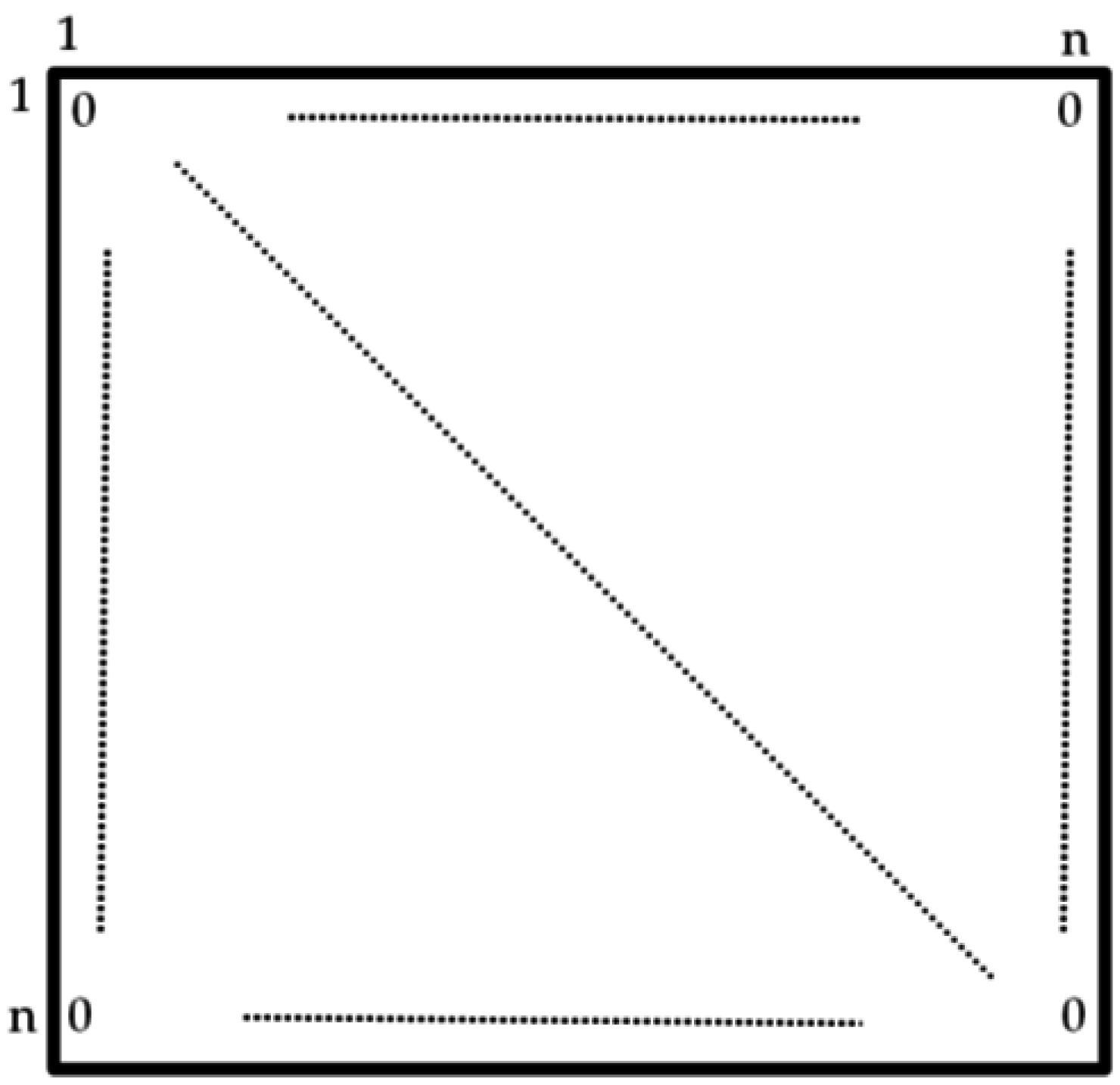
4. Method of Identifying Malfunctioning Robots Using the Byzantine Algorithm

Malfunctioning robots do not follow the direction guidance algorithm described in Section 3.2, but guide a user to a direction unrelated to the destination. Malfunctioning robots are identified using the algorithm used to solve the Byzantine generals’ problem [21]. This algorithm requires that the robots in the area share certain information. However, we do not allow robots to communicate with each other directly for two reasons. First, that would present a risk that malfunctioning robots send to other robots direction information that is different from what they display for users. Second, that would make it necessary to identify malfunctioning robots based on the directions each robot has displayed for users. Instead, robots communicate with each other using store-carry and forward-type M2M communication, in which information to be sent from one robot to another is stored in a user’s mobile terminal and is carried in the terminal and then forwarded to other robots as the user moves about. This section describes the algorithm for identifying malfunctioning robots. This algorithm is based on a distributed cooperative protocol for store-carry and forward-type M2M communication and on certain information shared by robots.

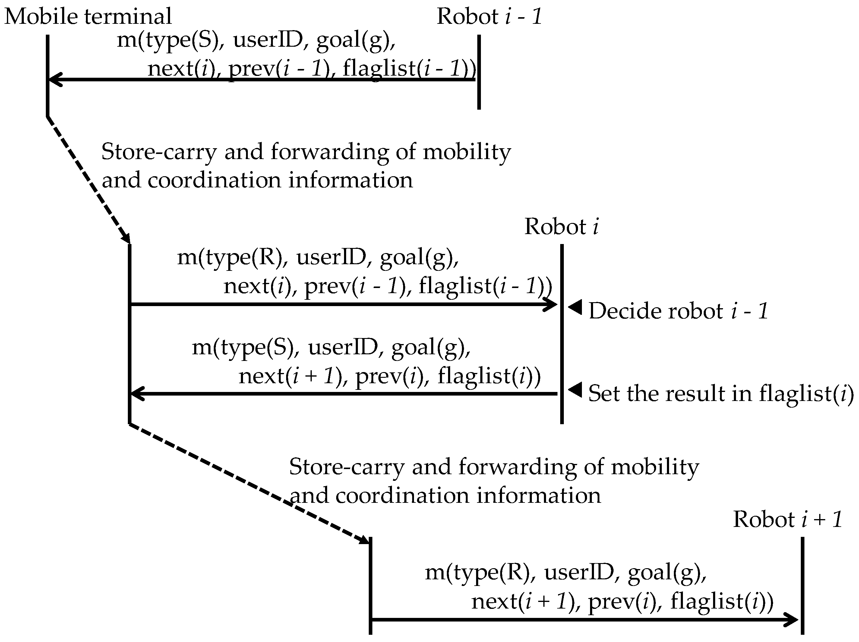
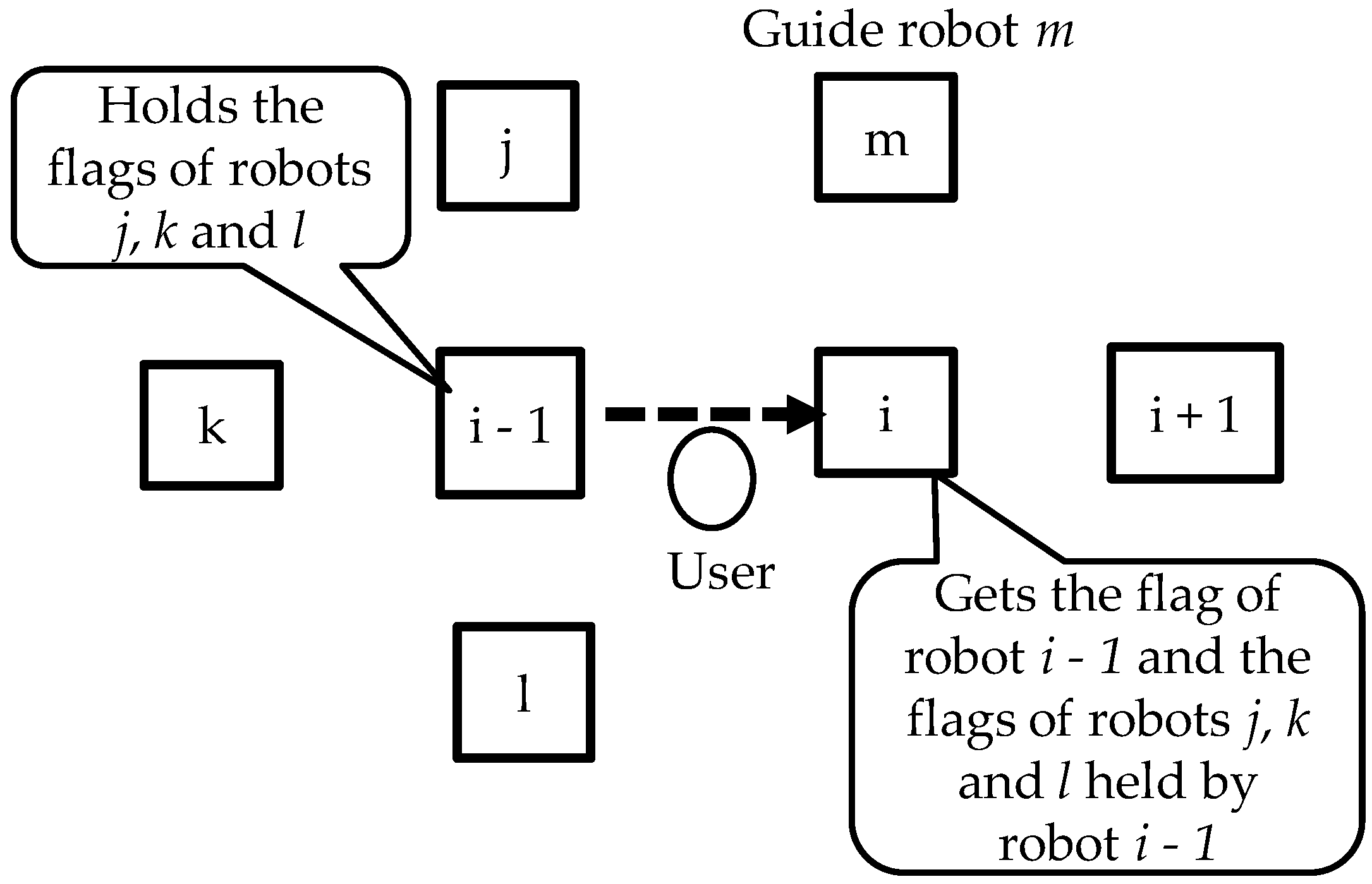
4.1. Distributed Cooperative Protocol for Store-Carry and Forward-Type M2M Communication

The general idea of a store-carry and forward-type M2M communication network is shown in Figure 6. Each message exchanged between a robot and a mobile terminal includes a message identifier (type), the user identifier (user ID), the robot ID of the robot located at the destination (goal), the robot ID of the robot toward which the user is to move (next), the robot ID received immediately before (prev) and a list of malfunctioning robots as identified by the robots by which the user has passed (flaglist).
Message exchange examples are described below based on Figure 6. When a mobile terminal communicates with robot A, it sends message m (which contains the type, user ID, goal, next, prev and flaglist) to the robot. After that, when the same mobile terminal communicates with robot B, it sends information about robot A, which gave it guidance immediately before, and receives guidance from robot B. After that, the mobile terminal communicates with robot C. It sends information about robots A and B and receives direction information from robot C. It compares the robot ID of the next robot toward which it is supposed to be guided immediately before and the robot ID of the robot toward which it has actually been guided. If the two robot IDs are different, the robot provisionally decides that the robot that provided guidance immediately before was malfunctioning and refrains from sharing the information in the flaglist.
The algorithm used by robots to process messages is described below. Messages are classified into two types: type(R) and type(S). Type(R) messages are guidance request messages that robots receive from mobile terminals. Type(S) messages are guidance messages that robots send to mobile terminals. The algorithm for identifying malfunctioning robots is described in Section 4.2.
Step 1: When robot i − 1 receives a guidance request message from a mobile terminal, it decides on the robot toward which the user should move in accordance with the algorithm described in Section 3.2. Robot i − 1 sets the value of next in i, the value of prev in i − 1 in the guidance message to send and sends the message to the mobile terminal. At the same time, it displays the user ID and the appropriate arrow on the screen.
Step 2: When the user comes near robot i in accordance with the guidance given by robot i − 1, his or her mobile terminal sends a guidance request message to robot i.
Step 3: Robot i decides the ID of the adjacent robot toward which it is to guide the user from the location coordinates (prev.x, prev.y) of robot i − 1 and the location coordinates (goal.x, goal.y) of the destination using the algorithm described in Section 3.2 and sets the ID in pnext.
Step 4: Robot i compares the values in next and pnext to check the legitimacy of robot i − 1.
Case 4-1: If the values in next and pnext are identical, robot i sets the value of the flag of robot i − 1 in its flaglist to “true”. It obtains flaglist(i − 1) of robot i − 1 contained in the guidance request message and shares information about how other robots have determined the malfunctioning of robots that are not adjacent to it.
Case 4-2: If the values in next and pnext are not identical, robot i sets the value of the flag of robot i − 1 in its flaglist to “false”. It does not obtain flaglist(i − 1) of robot i − 1 contained in the guidance request message.
Step 5: Robot i selects robot i + 1 toward which the user should move in accordance with the algorithm described in Section 3.2. It sets the value of next in i + 1 and the value of prev in i in the guidance message to send and sends the message to the mobile terminal. At the same time, it displays the user ID and an appropriate arrow on the screen.
Examples of message exchanges between a mobile terminal and robots as described above are shown in Figure 7.

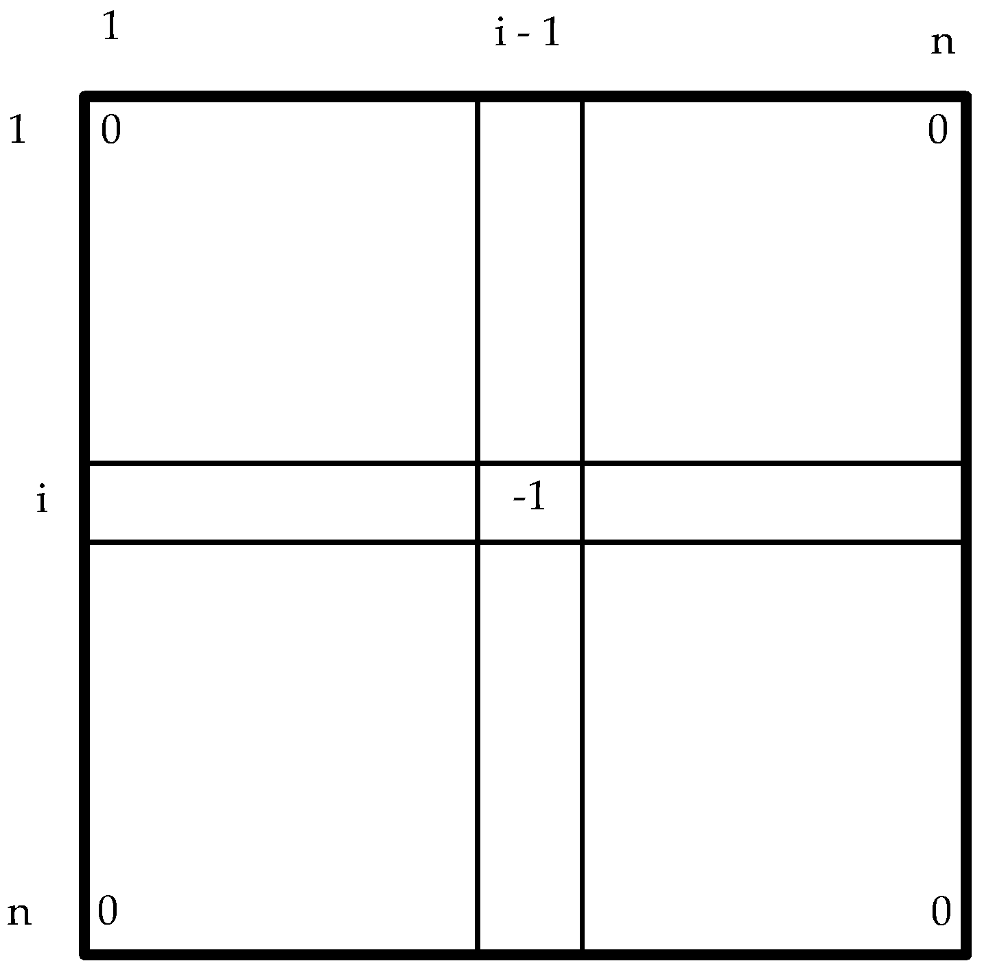
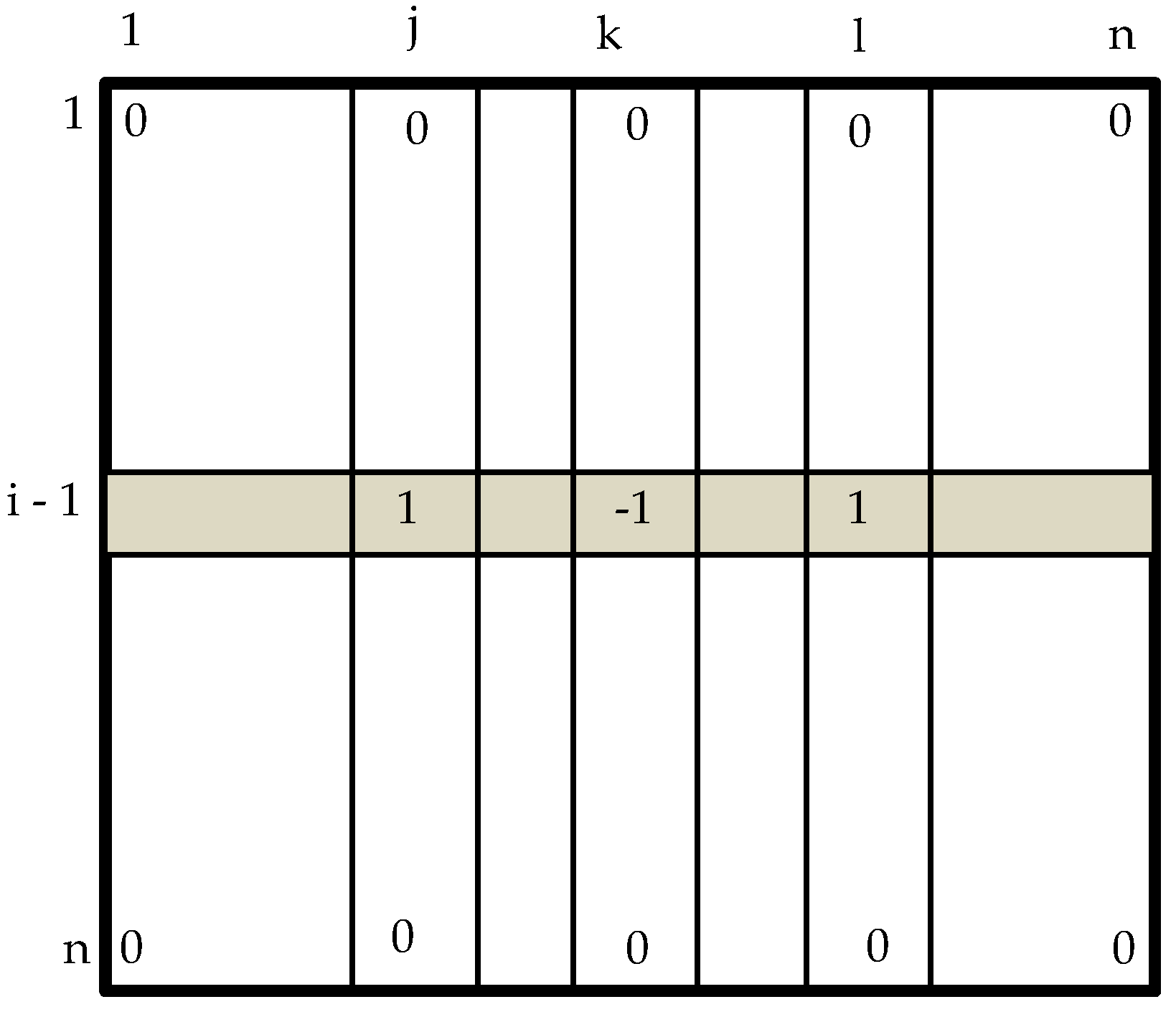
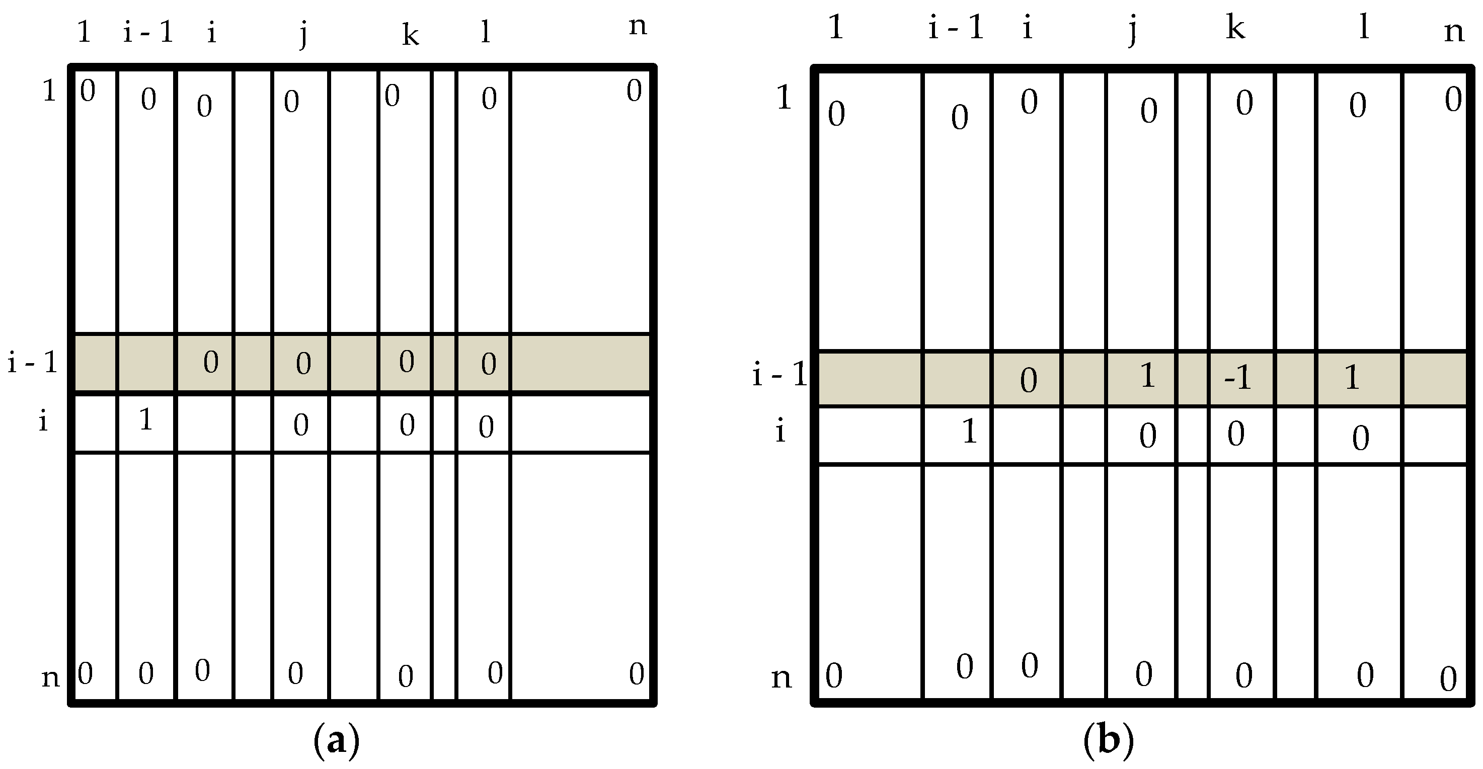
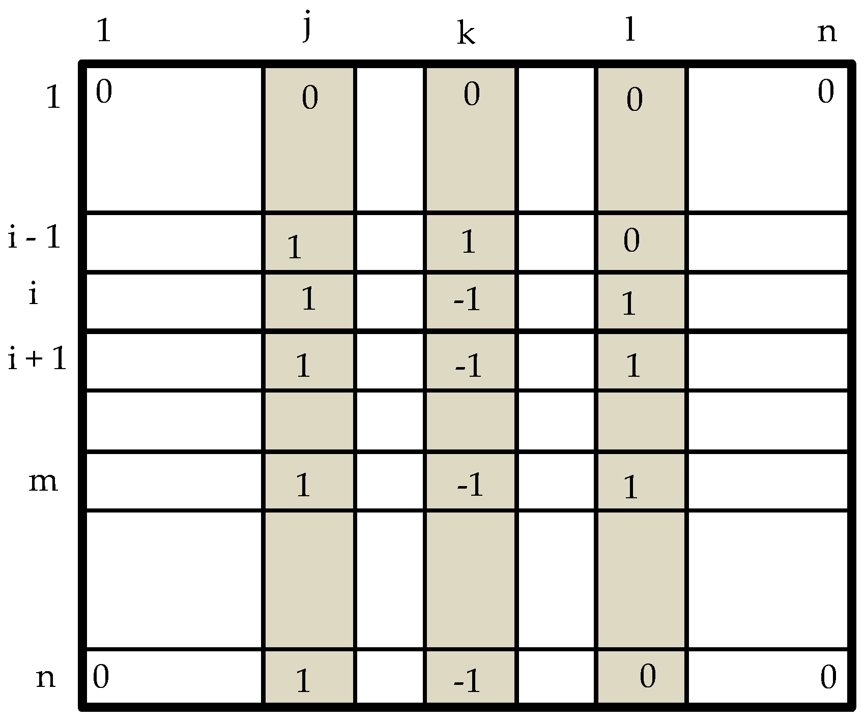
4.2. Algorithm for Identifying Malfunctioning Robots

Since there is only a small number of robots near each robot, the number of flags set in the flaglist is rather limited. To identify malfunctioning robots from flag values (true or false), robots must exchange the flag values set in other robots via mobile terminals using the protocol described in Section 4.1. Suppose there are n robots. To manage malfunctioning robots, each robot holds a flaglist, which takes the form of an n × n matrix (Fn) shown in Figure 8. Each element f in the Fn is initialized to “0”. The values (one to n) on the vertical axis of Figure 8 are the IDs of checking robots, and the values (one to n) on the horizontal axis are the IDs of robots that are checked. If robot i has provisionally decided that robot i + 1 is malfunctioning in Step 4 in Section 4.1, “−1”, indicating “false”, is set in the matrix, as shown in Figure 9.
Fn = {fij}1≤i,j≤n
When the number of flags for a certain robot (say robot A) in the flaglist of say robot B reaches a certain threshold number, robot B decides whether robot A is operating correctly or malfunctioning. Ideally, this decision should be made when flags for robot A are collected from all of the robots, but that is not likely to happen within a limited time because flaglist exchanges depend on the movements of mobile terminals. The number of flags that is considered sufficient for deciding whether a certain robot is malfunctioning is referred to as the “pseudo-synchronization number”, Nps. When the number of flags collected reaches Nps, a decision is made as to whether the robot concerned is malfunctioning. This is done by a majority vote as shown in Equation (3).
Number of “false” values of robot i ≥ (Nps ÷ 2)
The algorithm for determining a malfunction robot is as follows:
Step 1: Repeat the following until the column of Fn goes from j = 1 to n.
Step 2: At column j of Fn, calculate the number of elements where a provisional flag of either “true” or “false” is set, NXi.
Step 3: Examine whether the number of robots for which flags have been collected is Nps or higher.
Case 3-1: If the number is less than Nps (NXi < Nps), go to Step 1.
Case 3-2: If the number is equal to or greater than Nps (NXi ≥ Nps), go to Step 4.
Step 4: At column j of Fn, calculate the number of elements where “false” is set, NFi.
Step 5: Identify a malfunctioning robot in the following manner:
Case 5-1: If NFj < (Nps ÷ 2), determine that robot j is operating correctly. Go to Step 1.
Case 5-2: If NFj ≥ (Nps ÷ 2), determine that robot j is malfunctioning. Go to Step 6.
Step 6: Disqualify any robot that is found to be malfunctioning from being a guide robot. Go to Step 1.
The algorithm for determining a malfunctioning robot is described below using a specific example. Suppose that robots i − 1, i, I + 1, j, k, l and m are located as shown in Figure 10. In the flaglist of robot i − 1, the flags for nearby robots j, k and l are set as shown in Figure 11. When the user is guided from robot i − 1 to robot i and his or her mobile terminal communicates with robot i, the mobile terminal sends the flaglist of robot i − 1 to robot i. This flaglist is stored in the flaglist of robot i. Figure 12 shows the flaglist of robot i before and after the message reception.
A flaglist example for the case where Nps is five is shown below. In this example, “true” is represented by “1” and “false” by “−1”. In Figure 13, the number of flags for robot j and that for k are both five, which means that the pseudo-synchronization number is satisfied. Robot i sees that the number of “false” values for robot j is zero, and so, it decides that robot j is operating correctly. On the other hand, the number of “false” values for robot k is four. Therefore, robot i decides that robot k is a malfunctioning robot. The number of flags collected for robot i is three, which means that the pseudo-synchronization number is not yet satisfied. Therefore, no attempt is made to decide whether robot i is operating correctly or not.

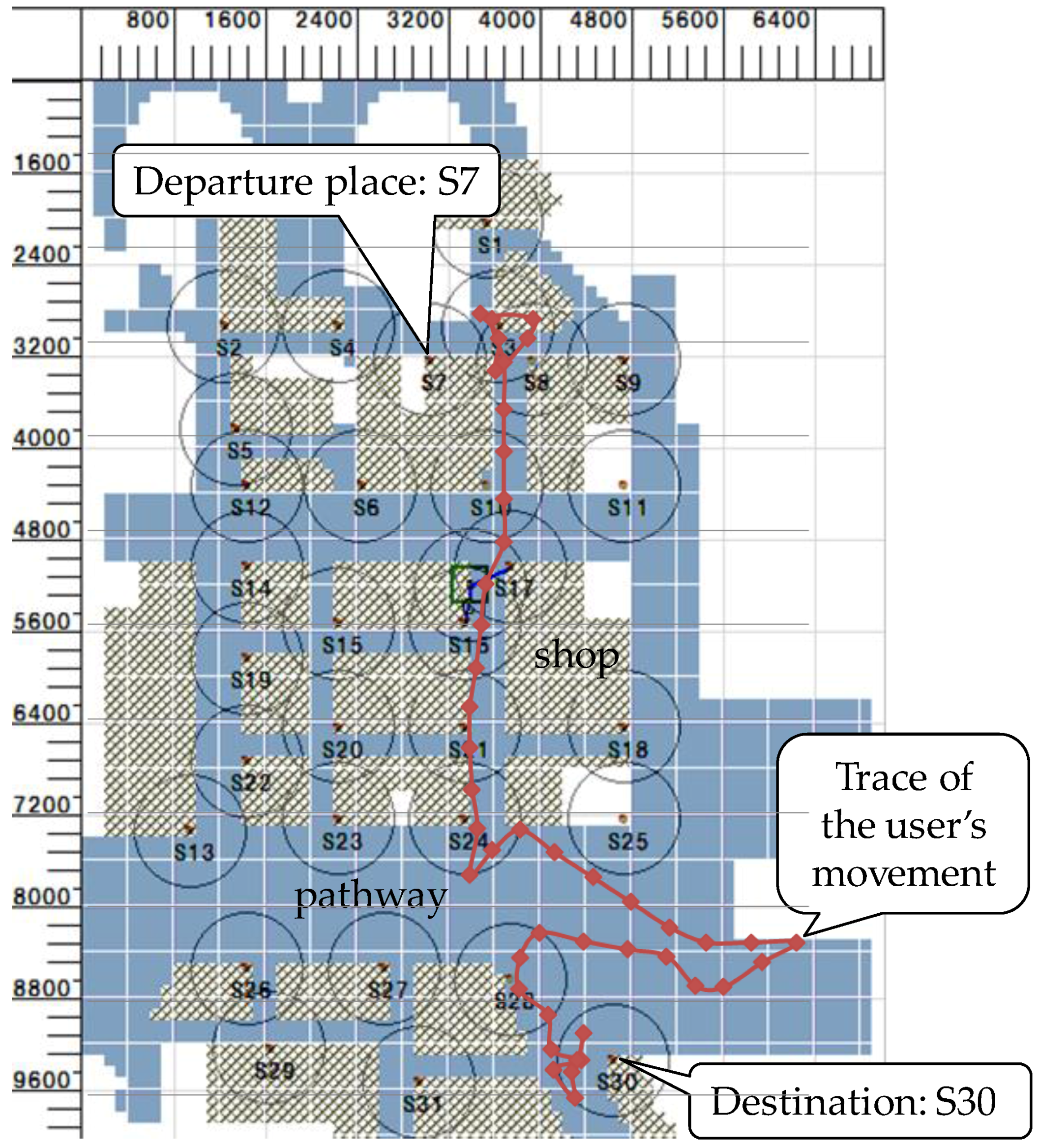
5. Evaluation System

We have built an evaluation system by adding the above-proposed functions to a simulator [22] that the authors had developed earlier. This system allows a variety of functions to be defined on a virtual node (VN) based on socket communication. The mobility (movement) of a VN can also be specified. Digital signage units and other electronic advertising media have become economically viable and have been installed in large numbers in recent years. They are often found in railway stations and shopping malls. Our evaluation assumes that a virtual robot is implemented on each of the signage units installed at different places in an underground shopping mall and that the robots provide a service of guiding individual users to the shops they want to visit. Specifically, we coded and implemented a 105-m-by-70-m area of an actual underground shopping mall called Tobu Hope Center [19]. The system displays the traces of the movements of VNs within the mall. Two types of VN are defined: mobile terminals (clients) and robots (servers). The M2M functions simulated include wireless zones required for near field communication (zone), processing of the distributed cooperative protocol that involves message exchanges (message) and connection resource management (resource). A function to compare collected items of information and identify malfunctioning robots (decision) is also implemented. The H2M functions implemented include the guidance algorithm (algorithm) and the function for controlling the screen display for users. The software configuration of the system is shown in Figure 14. The function for displaying the locations of malfunctioning robots has not been implemented. The software environment was built by installing Microsoft Visual C++2010 on Windows 7.
In this system, a robot is mounted on each of 31 signage units, S1 to S31, as shown in Figure 15. The figure also shows an example of a user moving from the departure place, S7, to the destination, S30, for the case where there is no malfunctioning robot.

6. Evaluation Results

This section presents simulation conditions and simulation results regarding the rate of identifying malfunctioning robots, the rate of reaching destination and the average length of time to reach the destination.

6.1. Simulation Conditions

There were 31 signage units. The number of users (number of mobile terminals) was varied from 10 to 100. The user’s behavior model was a random walk model. The users moved only on pathways. The processing interval was 1 s. The simulation duration was 10 min. The user’s moving speed was 3.6 km/h. The reach of wireless communication was 10 m. There were three malfunctioning robots (S5, S10 and S15). When a malfunctioning robot communicated with a mobile terminal, it displayed a randomly-selected direction arrow. These simulation conditions are summarized in Table 1.

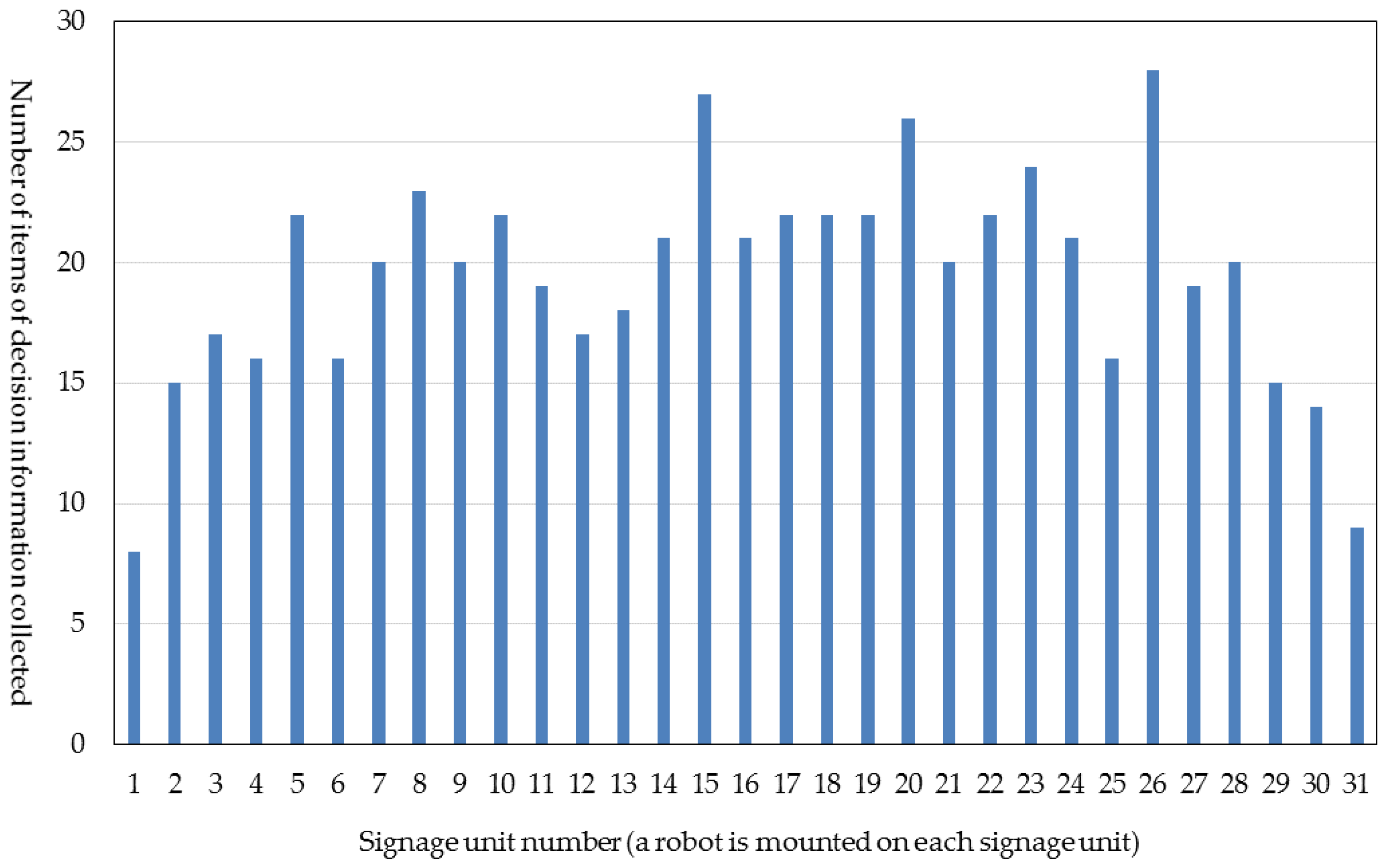
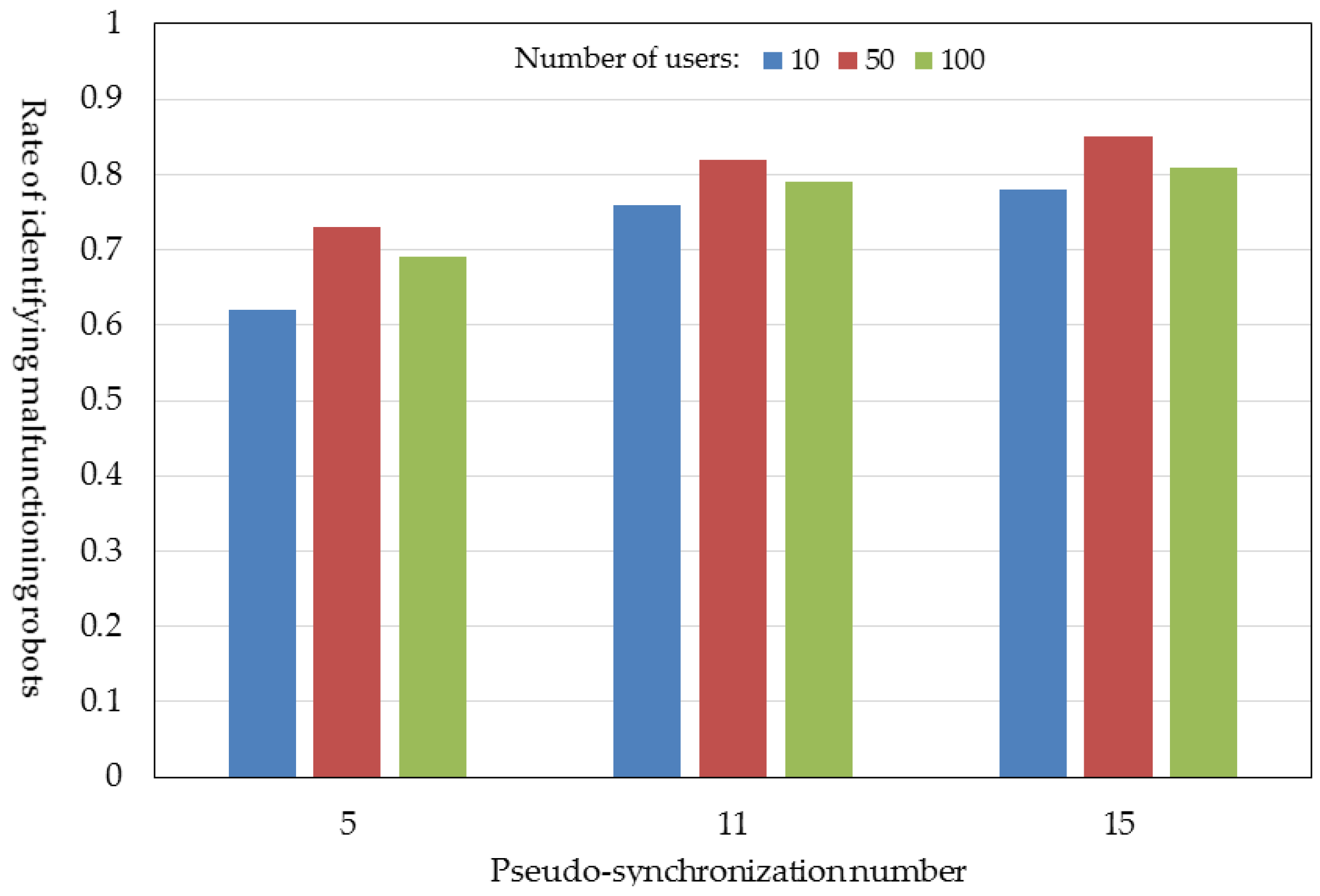
6.2. Number of Robots for Which Decision Information (Flag Value) Is Collected and the Pseudo-Synchronization Number

We measured the number of robots for which decision information (flag value) had been collected by the end of simulation. The result is shown in Figure 16. Those robots that were located at the edge of the mall area had fewer opportunities to communicate with mobile terminals, and thus, the number of robots for which decision information was collected was small. On the other hand, those near the center of the mall area had more users passing by and, thus, more opportunities to communicate with mobile terminals. They collected more items of decision information, with the result that more than 15 robots collected decision information for 15 or more robots. In fact, more than 90% of the 31 robots obtained decision information for 15 or more robots.

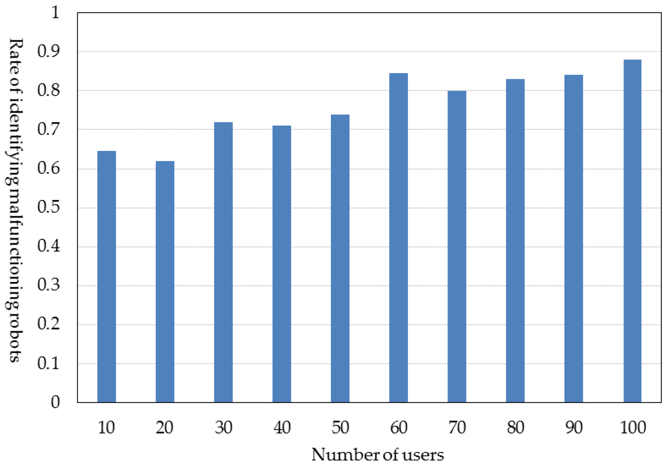
6.3. Rate of Identifying Malfunctioning Robots

The rate (probability) of identifying malfunctioning robots (identification rate) is defined as in Equation (4).
Rate   of   identifying   malfunctioning   robots = i = 1 N t T i / i = 1 N t F i
where Ti: the number of malfunctioning robots that are correctly identified by correctly-operating robot i; Nt: the number of correctly-operating robots within the area; Fi: the number of malfunctioning robots that should be identified by correctly-operating robot i.
The identification rate versus the number of users is shown in Figure 17. Overall, malfunctioning robots were identified at a probability of 0.7 to 0.8. The greater the number of users, the higher the identification rate because the greater the number of users passing by, the greater the number of robots to which flag values can be conveyed. However, the rate does not always improve with an increase in the number of users because of the restriction on the number of simultaneous connections to a robot. The identification rate (percentage) did not reach 100% because users stood still when they reached their destinations. This decreased the number of mobile terminals that communicated with robots to convey flag values.
We varied the pseudo-synchronization number from 5, 11 to 15. We also varied the number of users from 10, 50 to 100. The result is shown in Figure 18. The greater the pseudo-synchronization number, the greater the amount of information is available for identifying malfunctioning robots. Thus, in cases where the pseudo-synchronization number was 11 or 18, the identification rate went up to 0.7 to 0.8. Similarly, the greater the number of users, the higher the probability at which flag values are conveyed to other robots. Thus, the identification rate improves. However, the rate does not always improve with an increase in the number of users because of the restriction on the number of simultaneous connections to a robot.

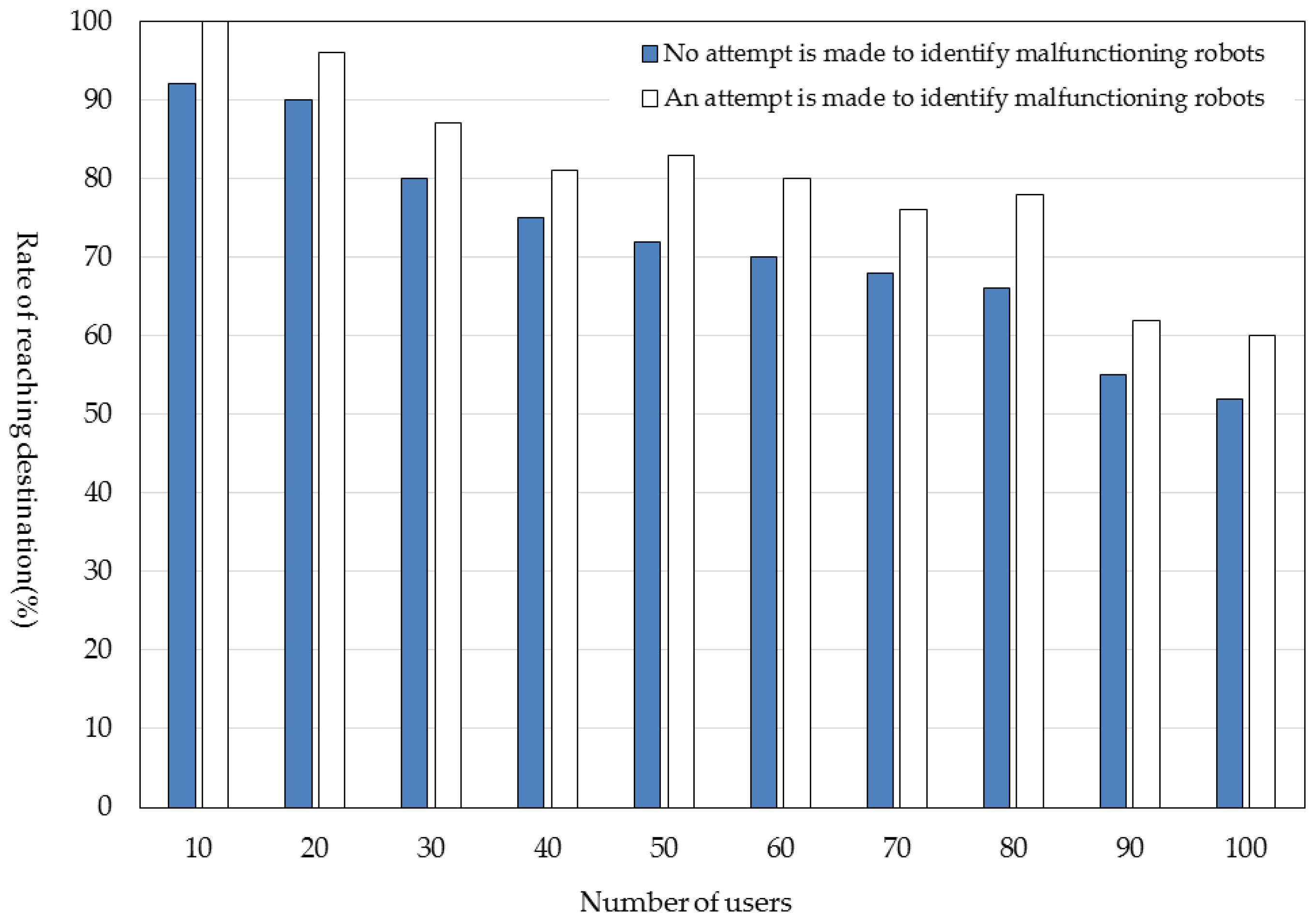
6.4. Rate of Reaching Destination

The rate (probability) at which users reach their destinations (reaching rate) is defined as in Equation (5).
Rate   of   reaching   destination = Number   of   users   who   reached   their   destinations Number   of   all   users
Comparison of the reaching rate for the case where no attempt was made to identify malfunctioning robots with the reaching rate for the case where such an attempt was made is shown in Figure 19. The reaching rate for the case where an attempt was made to identify malfunctioning robots is about 10% higher than that for the case where no such attempt was made. When malfunctioning robots were not identified and thus not eliminated, users were deceived by malfunctioning robots and failed to reach their destinations more often. Since the number of simultaneous connections that can be set up by each robot was limited, the reaching rate decreased as the number of users increased.

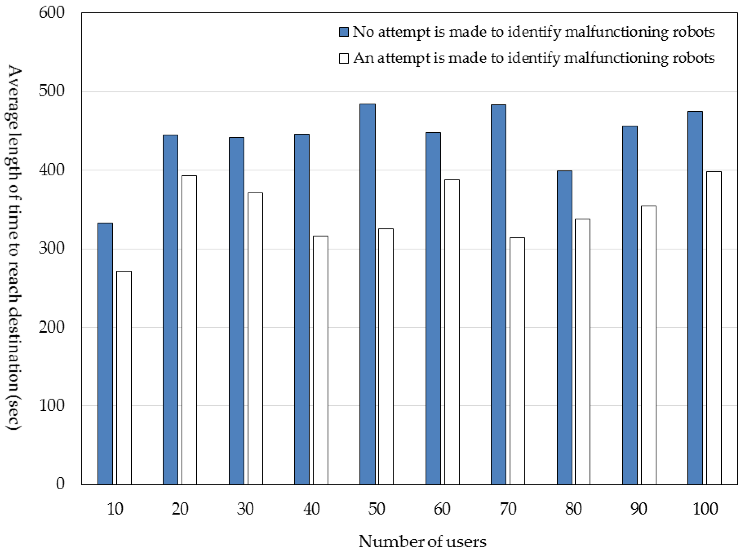
6.5. Average Length of Time to Reach Destination

The average length of time it took for users to reach their destinations is defined as in Equation (6).
  Average   length   of   time   to   reach   destination   = Total   length   of   time   to   reach   destination   of   the   users   who   reached   their   destinations Number   of   users   who   reached   their   destinations
The comparison of this average length of time for the case where no attempt was made to identify malfunctioning robots with that for the case where such an attempt was made is shown in Figure 20. The average length of time to reach the destination for the case where an attempt was made to identify malfunctioning robots was 1 to 2 min shorter than that for the case where no such attempt was made. When an attempt was made to identify malfunctioning robots, users were not guided to malfunctioning robots. This detoured users temporarily, but in the end, the average length of time it took to reach the destination was shortened.

7. Conclusions

This paper concerns a service in which robots guide users to their destinations. It has proposed a store-carry and forward-type M2M communication protocol enabling robots to work together and a method of identifying malfunctioning robots using the Byzantine algorithm. The effectiveness of these has been evaluated using simulation. It has been shown that malfunctioning robots can be identified correctly by making robots share information about how other robots judge other robots. The rate of identifying malfunctioning robots improves as the number of users increases because an increase in the number of users, who pass information about malfunctioning robots from one robot to another, provides a greater opportunity for robots to share this information. We have introduced the concept of the pseudo-synchronization number. Use of this number makes it possible to identify malfunctioning robots at a percentage of 70 or 80, even when each robot has not collected information about malfunctioning robots from all of the other robots.
Looking forward, it is necessary to evaluate the rate of identifying malfunctioning robots when the numbers and locations of malfunctioning robots are varied. It is also necessary to add to the evaluation system a function for making users who have reached their destinations move on to other destinations so that the number of moving users will stay more or less constant.

Author Contributions

Yoshio Suga designed the proposed method, developed the software prototype of the evaluation system, collected the evaluation data and wrote the initial draft of the paper. Kazumasa Takami provided the direction for his research activities and refined the proposed method, the analysis of the evaluation results and the writing of the paper. Both authors have read and approved the final manuscript.

Conflicts of Interest

The authors declare no conflict of interest.

References

  1. Chandrasekaran, B.; Conrad, J.M. Human-robot Collaboration: A Survey. In Proceedings of the Annual IEEE SoutheastCon Conferences (SoutheastCon 2015), Fort Lauderdale, FL, USA, 9–12 April 2015.
  2. Siegwart, R.; Arras, K.O.; Bouabdallah, S.; Burnier, D.; Froidevaux, G.; Greppin, X.; Jensen, B.; Lorotte, A.; Mayor, L.; Meisser, M.; et al. Robox at Expo.02: A Large Scale Installation of Personal Robots. Robot. Auton. Syst. 2003, 42, 203–222. [Google Scholar] [CrossRef]
  3. Shiomi, M.; Kanda, T.; Ishiguro, H.; Hagita, N. Interactive Humanoid Robots for a Science Museum. IEEE Intell. Syst. 2007, 22, 25–32. [Google Scholar] [CrossRef]
  4. Gockley, R.; Forlizzi, J.; Simmons, R. Interactions with a Moody Robot. In Proceedings of the 1st ACM SIGCHI/SIGART Conference on Human-Robot Interaction (HRI2006), Salt Lake City, UT, USA, 2–4 March 2006; pp. 186–193.
  5. Kanda, T.; Hirano, T.; Eaton, D.; Ishiguro, H. Interactive Robots as Social Partners and Peer Tutors for Children: A Field Trial. J. Hum. Comput. Interact. 2004, 19, 61–84. [Google Scholar]
  6. Tanaka, F.; Cicourel, A.; Movellan, J.R. Socialization between Toddlers and Robots at an early Childhood Education Center. Proc. Natl. Acad. Sci. USA 2007, 104, 17954–17958. [Google Scholar] [CrossRef] [PubMed]
  7. Tezuka, H.; Katafuchi, N.; Nakamura, Y.; Machino, T.; Nanjo, Y.; Iwaki, S.; Shimokura, K. Robot Platform Architecture for Information Sharing and Collaboration Among Multiple Networked Robots. J. Robot. Mechatron. 2006, 18, 325–332. [Google Scholar]
  8. Nakamura, Y.; Machino, T.; Motegi, M.; Iwata, Y.; Miyamoto, T.; Iwaki, S.; Muto, S.; Shimokura, K. Framework and Service Allocation for Network Robot Platform and Execution of Interdependent Services. Robot. Auton. Syst. 2008, 56, 831–843. [Google Scholar] [CrossRef]
  9. Liu, Y.; Yang, J. A Ubiquitous and Cooperative Service Framework for Network Robot System. In Proceedings of the 2nd International Conference on Intelligent Robotics and Applications (ICIRA 2009), Singapore, 16–18 December 2009.
  10. Shiomi, M.; Kanda, T.; Glas, D.F.; Satake, S.; Ishiguro, H.; Hagita, N. A Network Robot System for Cooperative Guide Service in a Shopping Mall. J. Robot. Soc. Jpn. 2011, 29, 544–553. [Google Scholar] [CrossRef]
  11. Murakami, Y.; Nakanishi, H. Proposing GUI for Remotely Controlling Guide Robots. IPSJ SIG Technical Reports 2008, 11(2008-HCI-127), 79–86. Available online: http://id.nii.ac.jp/1001/00036580/ (accessed on 14 August 2016).
  12. Gross, H.M.; Boehme, H.; Schroeter, Ch.; Mueller, S.; Koenig, A.; Einhorn, E.; Martin, Ch.; Merten, M.; Bley, A. TOOMAS: Interactive Shopping Guide Robots in Everyday Use-Final Implementation and Experiences from Long-Term Field Trials. In Proceedings of the 2009 IEEE/RSJ International Conference on Intelligent Robots and Systems (IROS’09), St. Louis, MO, USA, 10–15 October 2009; pp. 2005–2012.
  13. Kemmotsu, K.; Koketsu, Y.; Iehara, M. Human Behavior Recognition Using Unconscious Cameras and a Visible Robot in a Network Robot System. J. Robot. Auton. Syst. 2008, 56, 857–864. [Google Scholar] [CrossRef]
  14. Boswarthick, D.; Elloumi, O.; Hersent, O. M2M Communications: A Systems Approach; Wiley: Chichester, UK, 2012. [Google Scholar]
  15. Bojic, I.; Granjal, J.; Monteiro, E.; Katusic, D.; Skocir, P.; Kusek, M.; Jezic, G. Communication and Security in Machine-to-Machine Systems. Wirel. Netw.r Mov. Objects 2014, 8611, 255–281. [Google Scholar]
  16. Ren, Y.; Chuah, M.C.; Yang, J.; Chen, Y. Detecting Blackhole Attacks in Disruption-Tolerant Networks through Packet Exchange Recording. In Proceedings of the IEEE International Symposium on a World of Wireless Mobile and Multimedia Networks (WoWMoM), Montreal, QC, Canada, 14–17 June 2010; pp. 1–6.
  17. Djenouri, D.; Khelladi, L.; Badache, A.N. A Survey of Security Issues in Mobile Ad Hoc and Sensor Networks. IEEE Commun. Surv. Tutor. 2005, 7, 2–28. [Google Scholar] [CrossRef]
  18. Yang, H.; Luo, H.Y.; Ye, F.; Lu, S.W.; Zhang, L. Security in Mobile Ad Hoc Networks: Challenges and Solutions. IEEE Wirel. Commun. 2004, 11, 38–47. [Google Scholar] [CrossRef]
  19. Tobu Hope Center. Available online: http://www.tobu-hope.co.jp/ (accessed on 15 August 2016).
  20. Suga, Y.; Takahashi, D.; Takami, K. Guiding Users to Shops Using the Near-Field Communication between Signages and Mobile Terminals. In Proceedings of the 2nd International Conference on Mobile and Wireless Technology (ICMWT2015), Bangkok, Thailand, 23–25 June 2015.
  21. Lamport, L.; Shostak, R.; Pease, M. The Byzantine Generals Problem. ACM Trans. Program. Lang. Syst. 1982, 4, 382–401. [Google Scholar] [CrossRef]
  22. Yamaguchi, T.; Takami, K. A Reference Point Construction Method Using Mobile Terminals and the Indoor Localization Evaluation in the Centroid Method. Computers 2015, 4, 155–175. [Google Scholar] [CrossRef]
Figure 1. Classification of robot services and the position of the present research.
Computers 05 00030 g001
Figure 2. Classification of attacks on store-carry and forward-type robot-to-robot (R2R) ad hoc communication networks and the attack type covered by the present research.
Computers 05 00030 g002
Figure 3. Architecture for multiple robots to work together. Notes: GUI and presentation: display duration management; algorithm: guidance algorithm; decision: identification of malfunctioning robots; message: processing of the distributed cooperative protocol; resource: connection resource management; zone: processing of radio propagation area.
Computers 05 00030 g003
Figure 4. Example of navigation by guide robots at Tobu Hope Center (underground shopping mall) [19].
Computers 05 00030 g004
Figure 5. Angle-based algorithm. θ1 < θ2, so the direction is to D1.
Computers 05 00030 g005
Figure 6. Message exchanges in a store-carry and forward-type M2M communication network.
Computers 05 00030 g006
Figure 7. Examples of message exchanges between a mobile terminal and robots.
Computers 05 00030 g007
Figure 8. Fn structure of the flaglist held by each robot.
Computers 05 00030 g008
Figure 9. Example of the case where robot i decides that robot i − 1 is malfunctioning.
Computers 05 00030 g009
Figure 10. Layout of robots near robot i − 1.
Computers 05 00030 g010
Figure 11. Flaglist of robot i − 1.
Computers 05 00030 g011
Figure 12. Change in the flaglist of robot i after the message reception. (a) Flaglist before message reception; (b) flaglist after message reception.
Computers 05 00030 g012
Figure 13. Flaglist example of robot i (the element value is zero if no decision has been made, is one if “true” and is −1 if “false”).
Computers 05 00030 g013
Figure 14. Software configuration of the evaluation system. Notes: H2M: Human to Machine; presentation: display duration management; algorithm: guidance algorithm; decision: identification of malfunctioning robots; resource: connection resource management; battery: virtual node (VN) battery management; message: processing of the distributed cooperative protocol; MAC: MAC layer processing; zone: processing of radio propagation area; remote control: control of the movements of VNs on the monitor; display: drawing of the relative locations of VNs; base: basic emulator environment; CNV (conversion): association between the virtual IP address and real IP address; map model: underground shopping mall model; movement: movements of VNs; and monitor IF (interface): interface for image drawing on the monitor.
Computers 05 00030 g014
Figure 15. Underground shopping mall model, layout of signage units (robots) and a trace example of the user’s movement following the guidance given by robots.
Computers 05 00030 g015
Figure 16. Number of items of decision information collected by each robot by the end of the simulation.
Computers 05 00030 g016
Figure 17. Rate of identifying malfunctioning robots (pseudo-synchronization number = 15).
Computers 05 00030 g017
Figure 18. Change in the rate of identifying malfunctioning robots as the pseudo-synchronization number is changed.
Computers 05 00030 g018
Figure 19. Rate of reaching the destination (pseudo-synchronization number = 15).
Computers 05 00030 g019
Figure 20. Average length of time to reach destination (pseudo-synchronization number = 15).
Computers 05 00030 g020
Table 1. Simulation conditions.
ItemValue
Number of signage units31
Number of users (number of mobile terminals)Varied from 10 to 100
Behavior modelRandom walk
Moving speed3.6 km/h
Maximum number of simultaneous connections allowed: NL8
Display duration: TD30 s
Size of the underground shopping mall105 m × 70 m
Reach of wireless communication10 m
Simulation time10 min
Processing interval1 s
Number of simulation attempts5
Pseudo-synchronization number: NpsVaried from 5, 10 to 15
Guidance algorithmCorrectly operating robots: angle-based algorithm
Malfunctioning robot: random
Number of malfunctioning robots3 (S5, S10, and S15)

