3.1. Characterization of StarJet Prototype V2
Like mentioned before, results obtained with the previous setup V1 cannot be quantitatively compared to the current setup V2, because the designs of the actuator and the nozzle chips underwent major changes. Therefore, a full characterization of the novel device V2 was needed. As the StarJet technology features two different dispensing modes, the Drop-On-Demand-mode and the continuous-mode (for details see [
15]), experiments were performed using both operation modes. In continuous-mode, droplets are issued from the nozzle continuously at a certain “natural” frequency. This frequency primarily depends on dimensions of the ROT, the nozzle geometry, the liquid properties and the applied actuation pressure in combination with the rinse pressure. Keeping all parameters as constant as possible, still each nozzle chip design features an individual frequency range depending on the specific dimensions of nozzle diameter and star shaped bypass channels. For the first experiments with the StarJet V2, we used the “single channel” setup (
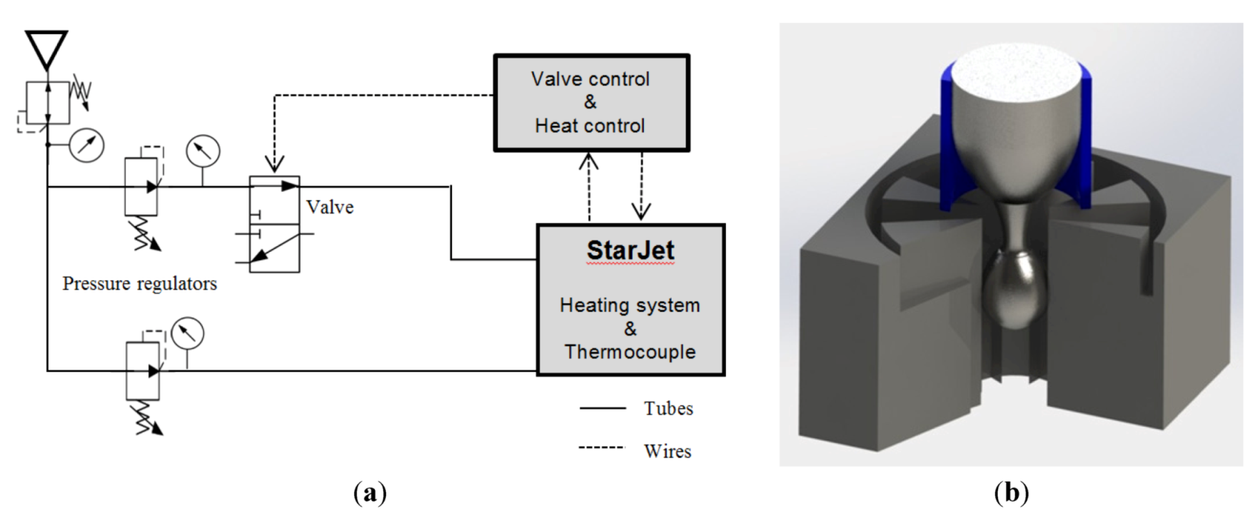
Figure 8) and compared the performance of different nozzle designs at different actuation pressures. In the “single channel” configuration, the internal channels for actuation and rinse pressure are connected, leading to a common inlet. Thus, the pressure values for actuation pressure and rinse pressure are kept on the same level during the experiments.
Figure 8.
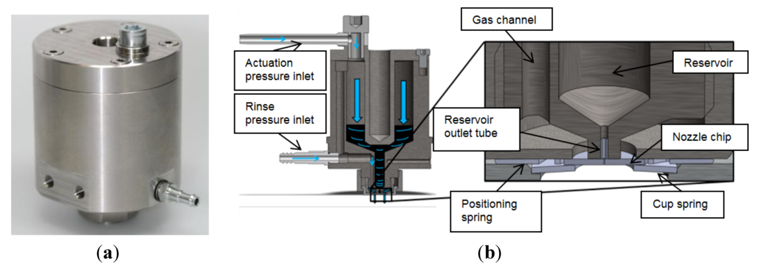
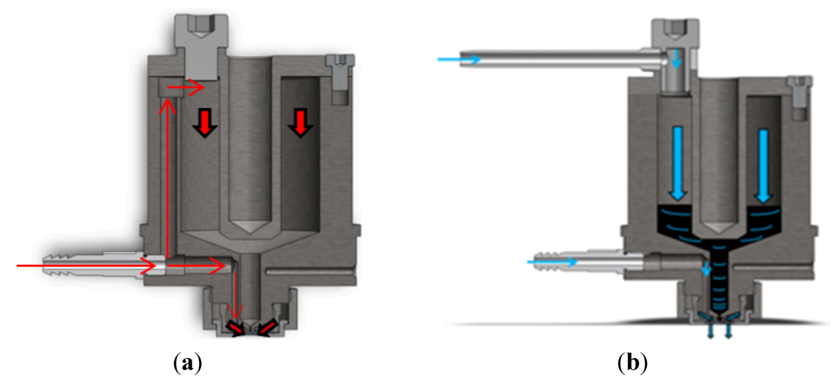
(a) Model cross section view of the StarJet V2 with a single gas supply for “single channel” operation; red arrows indicate the pneumatic gas flow. (b) Model cross section view of the StarJet V2 with two channel gas supply; blue arrows indicate the pneumatic gas flow.
Figure 8.
(a) Model cross section view of the StarJet V2 with a single gas supply for “single channel” operation; red arrows indicate the pneumatic gas flow. (b) Model cross section view of the StarJet V2 with two channel gas supply; blue arrows indicate the pneumatic gas flow.
Depending on the chip geometry (nozzle diameter, bypass channels,
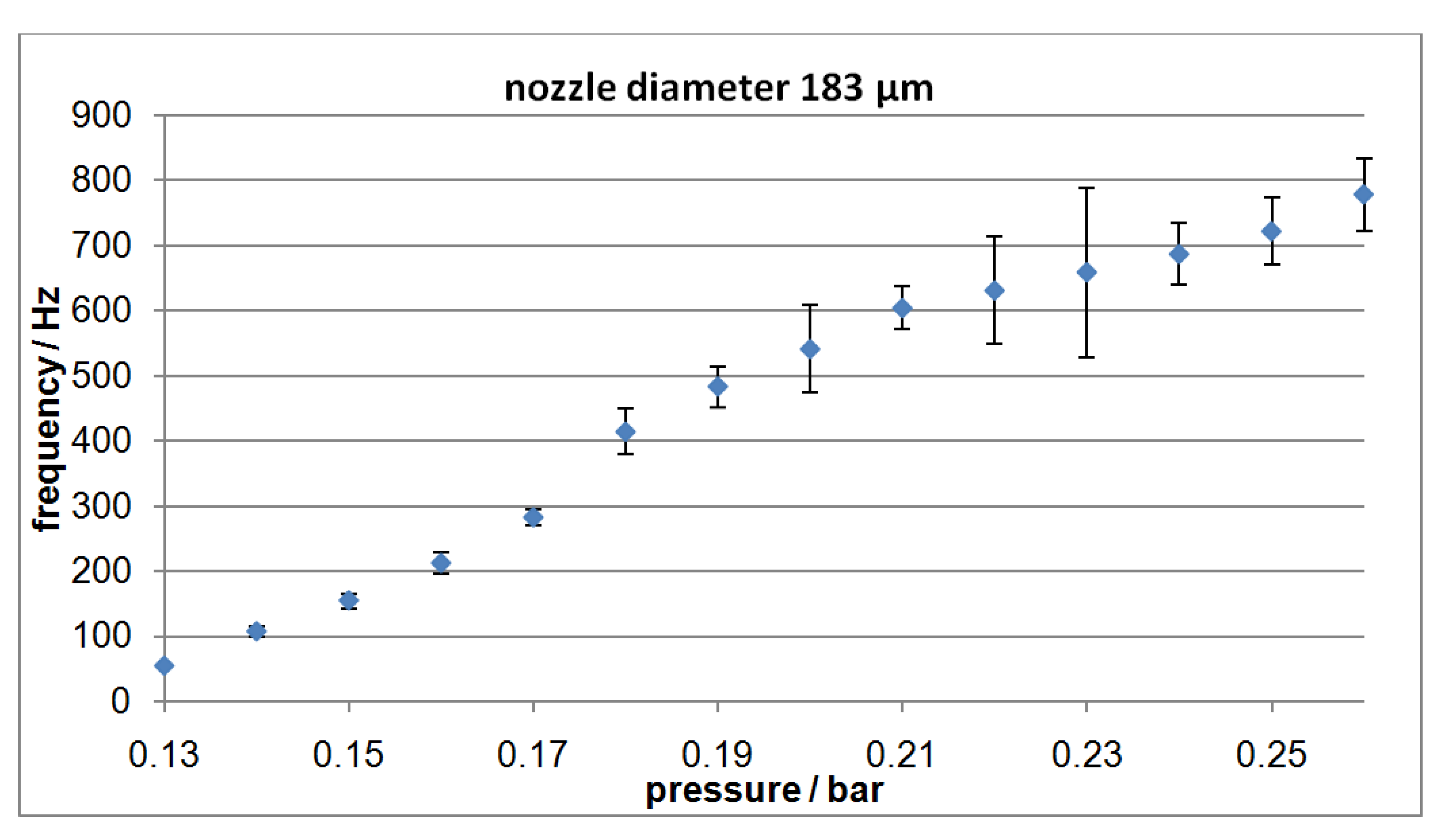
etc.), each type of nozzle chip can be operated in a certain frequency range. In that range, the droplet ejection frequencies can be adjusted in an almost linear way by the actuation pressure. Here, the minimum pressure, which is needed, depends on the nozzle design. For nozzles with smaller diameters, higher pressures are required.
Figure 9,
Figure 10 illustrate these circumstances. While
Figure 9 shows the correlation between the actuation pressure and the droplet generation frequency for a nozzle chip (#12) with a diameter of
D = 183 μm, the nozzle chip (#6) used for the experiments depicted in
Figure 10 had only a diameter of
D = 89 μm. The larger nozzle chip starts operation at a frequency of about 50 Hz at a minimum actuation pressure of 0.13 bar. By raising the pressure the frequency can be increased up to nearly 775 Hz before the chip stops generating droplets and starts continuous jetting at pressures higher than 0.26 bar. The smaller chip needs 0.18 bar to start operating like depicted in
Figure 10. Here, the adjustable range begins with a minimum frequency of approximately 740 Hz, and ends with almost 6500 Hz when a pressure of 0.32 bar is applied. When comparing the frequencies of the two nozzle chips for a fixed pressure value, for example at a pressure of 0.25 bar, it can be seen that the larger nozzle chip ejects droplets at approx.
f0.25bar = 720 Hz with a diameter of
D = 189 μm, while the smaller chip operates at a nearly 370% higher frequency of
f0.25bar = 2650 Hz and a droplet diameter of
D = 120 μm for the same pressure. This correspondents to a flow rate with respective coefficient of variation (CV) as calculated in
Table 2.
Table 2.
Calculated flow rate and coefficient of variation (CV) according to measurements depicted in
Figure 9,
Figure 10.
Table 2.
Calculated flow rate and coefficient of variation (CV) according to measurements depicted in Figure 9, Figure 10.
| Nozzle Chip Diameter | Mean Droplet Diameter | Minimum Flow rate | Maximum Flow rate | Minimum CV | Maximum CV |
|---|
| 183 μm | 189 μm | 175 nL/s | 2.7 μL/s | 0.7% | 19.7% |
| 89 μm | 120 μm | 669 nL/s | 5.8 μL/s | 3.0% | 12.3% |
Figure 9.
Droplet generation frequency as a function of the actuation pressure (one channel setup, nozzle chip (#12), number of measurements per data point N = 10.
Figure 9.
Droplet generation frequency as a function of the actuation pressure (one channel setup, nozzle chip (#12), number of measurements per data point N = 10.
Figure 10.
Droplet generation frequency as a function of the actuation pressure (one channel setup, nozzle chip (#6); number of measurements per data point, N = 10).
Figure 10.
Droplet generation frequency as a function of the actuation pressure (one channel setup, nozzle chip (#6); number of measurements per data point, N = 10).
The generated droplets were ejected into a surfactant-enriched water solution with a low surface tension in order to preserve a spherical droplet shape allowing a precise measurement of their diameter after solidification using an optical microscope. We have analyzed a sample of 387 droplets produced with a D = 144 μm diameter nozzle chip. In that case, the mean value amounts to Dmean = 148.4 μm with a standard deviation of 5.6 μm leading to a CV of 3.8%.
In order to improve our understanding of the dispensing process and especially the influence of the rinse pressure, the StarJet droplet generator V2 features two separate gas inlets (cf.
Figure 8b). Thus, the rinse pressure (lower inlet) can be adjusted independently of the driving pressure (upper inlet, cf.
Figure 8b). This enables droplet frequency adjustment at fixed driving pressure. If the rinse pressure applied via the bypass-channels is high enough to constrict the metal column, a droplet is generated. Otherwise, if
Prinse min is too small, the device starts producing a continuous molten metal jet.
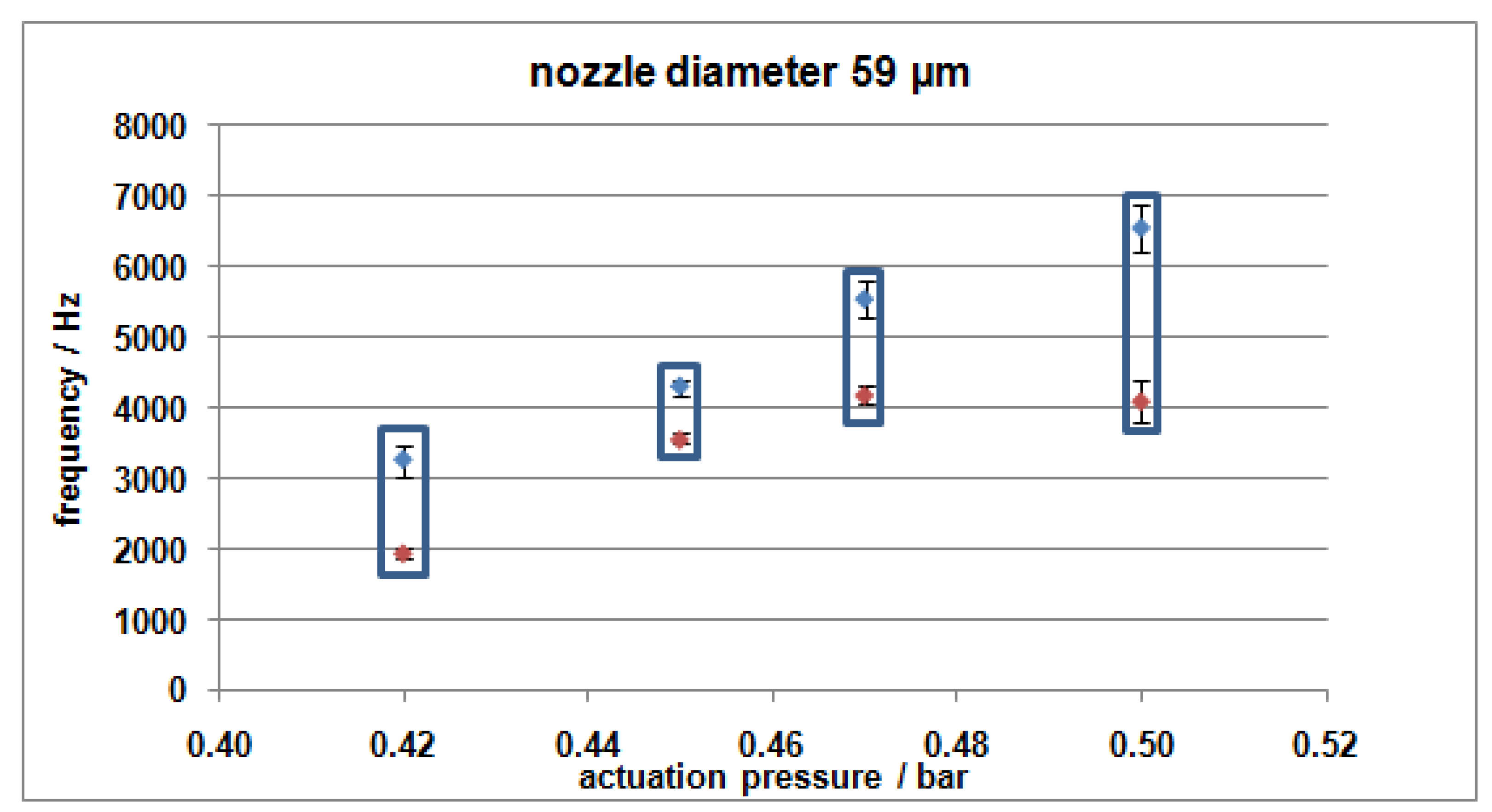
If the actuation pressure is kept at a constant value, the frequency rises with increasing rinse pressure up to a maximum value where the rinse pressure completely blocks the generation of droplets inside the nozzle and no liquid metal is ejected anymore at this actuation pressure value. In that way, the dispensing frequency can be controlled by the adjustment of these two pressure values. This zone is indicated by the blue frames in
Figure 11. Above a certain actuation pressure value, the liquid metal column is forced through the nozzle without being disturbed by the rinse pressure any more. Then, the maximum dispensing frequency for a certain nozzle chip design is exceeded. For instance
Figure 11 illustrates the dependency for a chip design with a nozzle diameter of 59 μm.
Figure 11.
Droplet generation frequency as a function of the rinse pressure (two channel setup) in combination with fixed actuation pressures. The blue marks (max. adjustable frequency for given actuation pressure) belongs to the highest rinse pressure for proper operation, and the red marks (min. adjustable frequency for given actuation pressure) belongs to the lowest rinse pressure for proper operation (nozzle diameter D = 59 μm).
In several experiments with different chip designs, frequencies in the range from
fmin = 200 Hz to
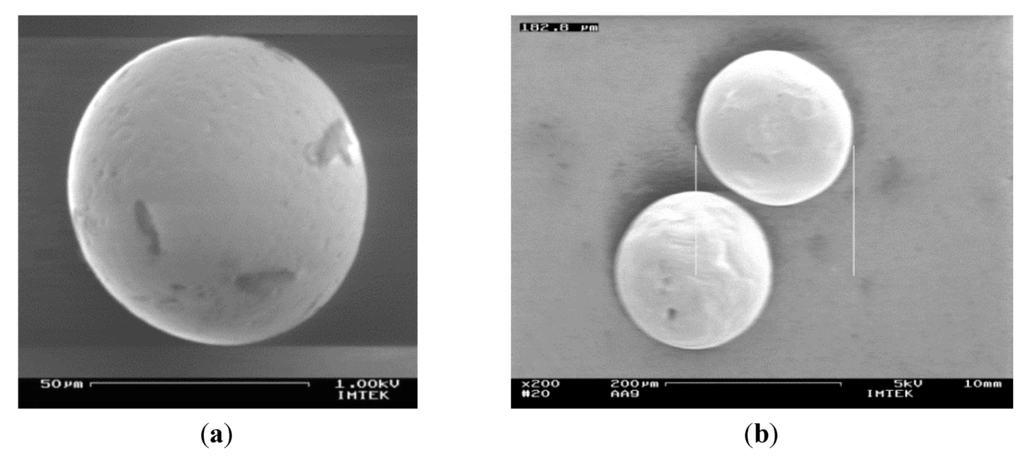
fmax = 11 kHz where evaluated. With the redesigned nozzle, a minimum droplet diameter of
Dmin = 60 μm (
Figure 12a) has been achieved using 50 μm nozzle chips (chip #5). We also observed that droplet trajectory and the occurrence of satellites can be optimized by the rinse pressure. The droplet diameter is primarily defined by the nozzle size (
D = 50 μm to 360 μm tested) and slightly influenced by the dispensing frequency.
For switching the device from continuous-mode to DoD-mode no setup changes are required. Only the control of the valve has to be changed. Instead of a continuous actuation pressure, the pressure is now applied in short pulses, each leading to the ejection of one single droplet. This is conducted by opening a solenoid valve periodically for a short time (typically
t = 2–5 ms). The rinse pressure is applied all the time to prevent oxidation at the nozzle outlet. A suitable valve opening time in combination with an appropriate actuation pressure has been experimentally determined for each nozzle chip, leading to the ejection of one single droplet. The used parameters are listed in
Table 3.
Table 3.
Printing parameters for Drop-on-Demand experiments.
Table 3.
Printing parameters for Drop-on-Demand experiments.
| | Nozzle Chip # 2 (59 μm) | Nozzle Chip # 6 (89 μm) | Nozzle Chip # 21 (144 μm) |
|---|
| Reservoir temperature | 320 °C | 320 °C | 500 °C |
| Valve opening time | 3 ms | 2 ms | 2 ms |
| Actuation pressure value | 0.25 bar | 0.2 bar | 0.2 bar |
| Rinse pressure value | 0.15 bar | 0.10 bar | 0.2 bar |
| Droplet diameter | 88 μm | 144 μm | 180 μm |
The printhead was successfully tested in DoD-mode for 5 h without interruption at frequencies up to 25 Hz and a temperature of
T = 320 °C. Then, the reservoir of the printhead was cleaned and filled with zinc alloy (ZAMAK, (Zn96Al4)
Tm = 420 °C). This was heated up to
T = 500 °C. Using a nozzle Chip #21 with an opening of
D = 144 μm, single monodisperse metal droplets were generated featuring a diameter of
D = 180 μm (see
Figure 12b).
Figure 12.
(a) SEM image of metal (solder: Sn95Ag4Cu) droplet dispensed into soar water with diameter of D = 60 μm. (b) SEM image of dispensed metal (ZAMAK: Zn96Al4) droplets with diameter of D = 180 μm.
Figure 12.
(a) SEM image of metal (solder: Sn95Ag4Cu) droplet dispensed into soar water with diameter of D = 60 μm. (b) SEM image of dispensed metal (ZAMAK: Zn96Al4) droplets with diameter of D = 180 μm.
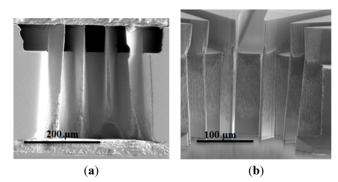
At the current development state of the StarJet, the limiting factor for the maximum operating temperature is the thermal stability of the used sealing materials (Nova-Mica-Thermex® up to 900 °C). Therefore, the so-far reached temperature of 500 °C does not reflect the upper limit of the system, and we plan to reach higher temperatures in order to print higher melting materials. In continuous mode, the lowest adjustable frequency was 200 Hz. Here, the limiting factor is the minimum achievable mass flow through the reservoir outlet tube, which is mainly defined by the actuation pressure that has to be applied to overcome the capillary pressure of the ROT. The maximum frequency is defined by the pressure value, which leads to a jetting behavior of the device. Then, the corresponding mass flow is too high and the molten metal, which enters the nozzle chip is not separated into single droplets. The size of the smallest droplets is defined by the nozzle chip. Here, the limiting factor is the fabricability of the nozzle chip geometry, because, due to decreasing diameters of the nozzle, the aspect ratio of the structures increases. This raises the difficulty of fabrication and especially the through etching of the nozzle chips. So far, we have successfully produced nozzle chips with diameters down to 50 μm.
3.2. Printing in DoD-Mode
For the printing experiments, we installed a nozzle (#6 with a diameter of
D = 59 μm) inside the printhead and heated it up to
T = 320 °C. We used solder (Sn95Ag4Cu) for these experiments, because this material provides a short heat-up and cool-down cycle, due to its low melting point (
Tmelt = 210 °C). For evaluating the long term stability of the process, we successfully printed a pattern consisting of more than 10,000 droplets onto a substrate using DoD-mode. Frequencies between 0.5 Hz and 25 Hz were selected. The pattern depicted in
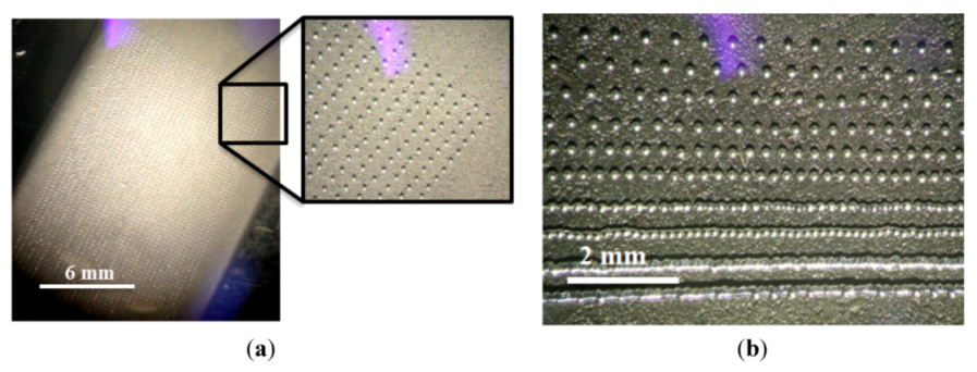
Figure 13 was printed without disruption at a frequency of 10 Hz with a pitch of 0.4 mm. The diameter of the droplets on the substrate was approximately 88 μm.
Figure 13.
(a) Picture of a Drop-on-Demand (DoD)-mode printed pattern (solder: Sn95Ag4Cu, droplet diameter D = 88 μm) using a constant pitch of 400 μm. (b) Picture of a DoD-mode printed pattern (solder: Sn95Ag4Cu, droplet diameter D = 144 μm) using an increasing pitch for each line (50 μm→500 μm).
Figure 13.
(a) Picture of a Drop-on-Demand (DoD)-mode printed pattern (solder: Sn95Ag4Cu, droplet diameter D = 88 μm) using a constant pitch of 400 μm. (b) Picture of a DoD-mode printed pattern (solder: Sn95Ag4Cu, droplet diameter D = 144 μm) using an increasing pitch for each line (50 μm→500 μm).
During the next experiments, we used a nozzle chip (#6) with a diameter of
D = 89 μm, resulting in droplets with diameters of approximately 144 μm. Here, the pitch was decreased continuously in steps of 50 μm from 0.5 mm to 0.05 mm. As can be seen in
Figure 13 (b), single droplets merge when the pitch gets smaller than the single droplet diameter. In that way, solid structures can be formed without using a reflow process.
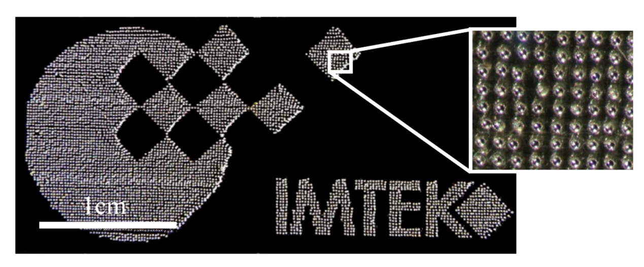
The software for controlling the stage system provides a so-called bitmap dispense mode, which enables to convert the pixels of a b/w bitmap into a grid of printed droplet with a given pitch. Using this mode, we printed the affiliation logo of our research institute on an aluminum substrate (see
Figure 14). Again, we used a nozzle chip (#2) with a diameter of
D = 59 μm, generating droplets of
D = 88 μm. This was done with a frequency of 5 Hz.
Figure 14.
Picture of a DoD-mode printed affiliation logo of the IMTEK; droplet diameter approx. 88 μm.
Figure 14.
Picture of a DoD-mode printed affiliation logo of the IMTEK; droplet diameter approx. 88 μm.
Again, using the nozzle chip (#6) with a diameter of
D = 89 μm (
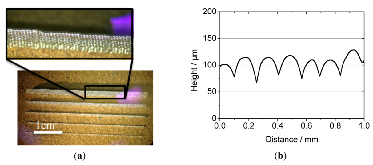
Ddroplet = 144 μm), a pitch of 150 μm and a droplet generation frequency of 10 Hz, we investigated the feasibility of fabricating three-dimensional structures. For instance, we printed multiple lines of solder on top of each other. The print distance was kept to 1.5 mm continuously by adjusting the z-axes. The printed walls had a length of 4 cm and heights up of 2 mm (see
Figure 15a). The rinse pressure was set to the minimal possible value leading to the generation of a droplet. In that way, the droplets had the lowest adjustable velocity when leaving the nozzle. Consequently, the droplets kept their spherical shape when they hit the surface (see
Figure 15a). So, the printed structures had a regular surface with average surface roughness of
Rt = 6.3 μm (see
Figure 15b,
Figure 16).
Figure 15.
(a) Picture of in DoD-mode printed IMTEK logo, droplet diameter approximately 144 μm. (b) Surface measurement of the printed wall.
Figure 15.
(a) Picture of in DoD-mode printed IMTEK logo, droplet diameter approximately 144 μm. (b) Surface measurement of the printed wall.
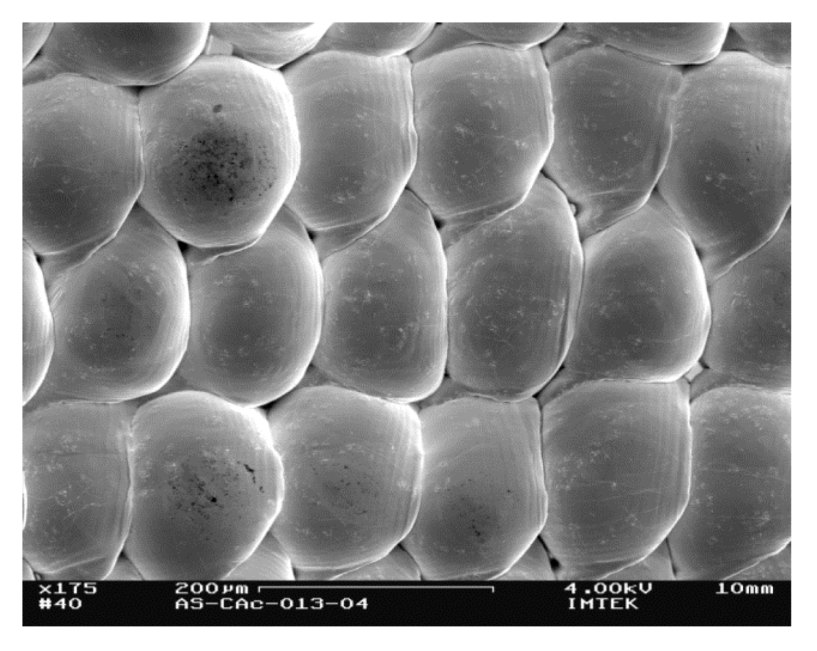
The close-up view shows that single droplets are precisely placed on top of each other without failures. Thus, strongly uniform structures can be created without, e.g., a thermal reflow process. This example demonstrates the small deviations of the droplet trajectory from the symmetry axis of the nozzle and the high uniformity of the droplets.
Figure 16.
Close up view (SEM picture) of in DoD-mode wall; droplet diameter approximately 144 μm.
Figure 16.
Close up view (SEM picture) of in DoD-mode wall; droplet diameter approximately 144 μm.
3.3. Printing in Continuous-Mode
For the printing experiments using the continuous-mode we printed droplets onto a rotating substrate. In that way, the pitch could be adjusted by adapting the distance between the center of the substrate and the printhead manually. We used a nozzle chip (#6) with a diameter of
D = 89 μm, ejecting droplets with diameters of
D = 120 μm, and the device was heated up to
T = 250 °C (
pactuation =
prinse = 0.3 bar). In contrast to the printing experiments in DoD-mode, the printing distance between the nozzle and the substrate was fixed at 15 mm and could not be adapted during printing. Using a frequency of approximately
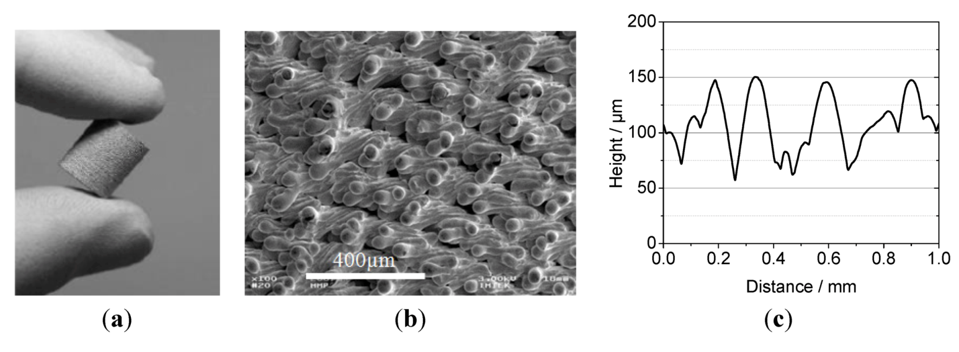
f = 4 kHz and a pitch two times larger than the respective droplet diameter, we created tube-like structures with porous walls, like depicted in
Figure 17.
Figure 17.
(a) Picture of a printed tube (diameter 10 mm). (b) SEM picture of the surface of a continuous-mode printed tube. (c) Surface measurement of the printed tube.
Figure 17.
(a) Picture of a printed tube (diameter 10 mm). (b) SEM picture of the surface of a continuous-mode printed tube. (c) Surface measurement of the printed tube.
The close-up view (see
Figure 17b) reveals that the droplets lose their spherical shape and solidify in a deformed state, while impinging on the solid. This leads to the high surface roughness, as well as to an enhanced wall thickness of 300 μm compared to the droplet diameter of
D = 120 μm. Based on the results of S.D. Aziz [
20], the reason for the splashing of the droplets is probably the higher velocity of the flying droplets caused by the larger rinse pressures. The surface of the printed structure has again been measured with a profiler (Tencor, P11) to characterize the roughness of the walls. The structure exhibits an average surface roughness of
Rt = 15.1 μm (see
Figure 17c).
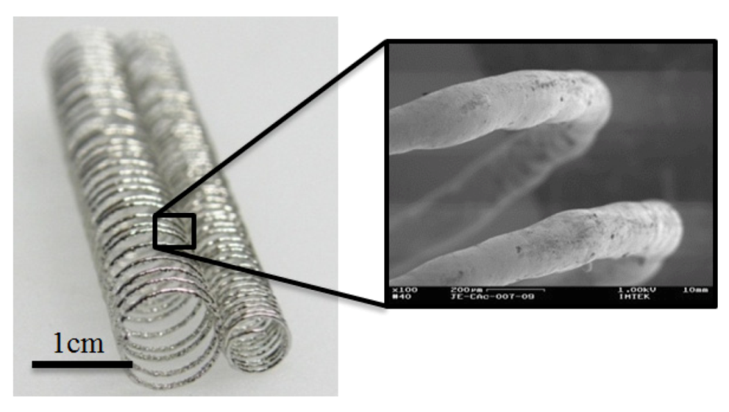
Figure 18.
Picture of two coils (Diameter 10 mm/6 mm) printed at 350 °C metal temperature with close up view (SEM-picture) of the surface.
Figure 18.
Picture of two coils (Diameter 10 mm/6 mm) printed at 350 °C metal temperature with close up view (SEM-picture) of the surface.
By dispensing (frequency of 5.5 kHz,
T = 350 °C) single droplets onto a horizontal spinning axis mounted on a linear stage while moving this spinning axis under the printhead, coils can be fabricated (see
Figure 18) using continuous operation mode. The adaptation of the dispensing frequencies and the rotation velocity of the axis allowed for printing homogeneous structures (pitch approx. 50 μm). Here, the single droplets merge after impact, resulting again in a solid structure (see close-up in
Figure 18). The samples have been created at room temperature without any additional heat conditioning or post treatment.
Remarkably, only minor oxidization occurs on the surface of the printed structures, which is attributed to the pneumatic actuation by nitrogen, as described above. These examples demonstrate that it is possible to influence the properties of the printed structures (morphology, porosity, wall thickness, roughness, etc.) by variation of the process parameters considerably.


