

Research on Detection and Safety Analysis of Unfavorable Geological Bodies Based on OCTEM-PHA


1
School of Resources and Safety Engineering, Central South University, Changsha 410083, China
2
Zijin School of Gelolgy and Mining, Fuzhou University, Fuzhou 350108, China
*
Author to whom correspondence should be addressed.
Remote Sens. 2023, 15(15), 3888; https://doi.org/10.3390/rs15153888
Submission received: 22 June 2023
/
Revised: 23 July 2023
/
Accepted: 4 August 2023
/
Published: 5 August 2023
(This article belongs to the Special Issue Remote Sensing for Geohazards Monitoring: Towards Refined Risk Analysis and Management)
Abstract
:The caving method and mining disturbance may cause geological issues. The advance prediction of unfavorable geological bodies should be conducted to ensure product safety in the underground mine. In this study, we proposed the OCTEM-PHA analysis process and analyzed the Tongkeng Mine in Guangxi. Further, we conducted opposing-coil transient electromagnetic method (OCTEM) detection on four detection lines in T5-1 stope at mine level 386 by using portable geological remote sensing equipment and created inversion maps. Plot profiles and coupling were analyzed with inversion maps to explore the five types of risk factors presented in the mine. The preliminary hazard analysis (PHA) method was used for five types of risk factors to predict the accident consequence and develop safety countermeasures. The results indicate the following: (1) the OCTEM-PHA safety analysis process for unfavorable geological bodies is realistic and feasible. (2) OCTEM shows an excellent response to both high- and low-resistance anomalies in practical engineering applications. The coupling analysis of profiles and inversion maps helps visually analyze the area of apparent resistivity anomalies. (3) The studied mine did not show overhanging formed by the overlying rock layer and large loose void areas. However, the crumbling mining area should be further optimized for balanced mining, the treatment of groundwater and surface water should be improved, and the comparative analysis with the follow-up detection results should be increased.
1. Introduction
As shallow resources in the mining industry continue to be exhausted, most metal mines have gradually shifted to medium-deep mining, and underground mining creates more safety problems [1,2,3]. During mining operations, mining disturbances may cause surface deformation, subsidence, and damage to surface structures [4], such as roof caving, rock strata movement, surface subsidence, water inrush [5], and other geological disasters, which are not conducive to safe production work. Among many mining methods, the caving method has the advantages of low cost, high efficiency, and various applications in underground mining at home and abroad [6]. However, studies have shown that caving mining can cause stress redistribution in the surrounding rock, resulting in rock movement and cracking [7,8], causing vast safety hazards. Therefore, conducting geological remote sensing detection of the hidden geological bodies regularly in the mining process [9] and safety analysis on the detection results, as well as formulating safe and effective management mechanisms, is essential for safe and efficient mining.
Currently, the detection methods of unfavorable geological bodies in rock masses, including the DC method detection, seismic method detection, ground penetration radar (GPR) detection, electromagnetic method detection [10,11], as well as joint multi-method detection that integrates these methods [12,13], are becoming increasingly mature and abundant. Among them, the DC method includes laying electrodes using the direct current power supply and studying the change in an electric field to detect unfavorable geological bodies. Cao et al. [14] used multifractal theory for data processing of DC method results and obtained a good response in both high- and low-resistance identification. Wang [15] proposed a ground–borehole direct current method, which supplies DC power on the ground and receives the potential difference in the borehole. The results show that this method significantly responds to per-borehole anomalies. Zhou et al. [16] designed three boreholes for advanced water exploration into a “triangular cone” and conducted advanced detection combined with the direct current method. The results showed that the response result of this method was far superior to the traditional detection method. The arrangement of electrodes in the DC method is limited by the roadway environment and is affected by the complex terrain, which is relatively difficult to install. The seismic method uses the different manifestations of seismic wave propagation in non-uniform geological bodies to predict unfavorable geological bodies. Hao et al. [17] used the seismic method to predict two mining voids in the excavation workings and deduced the exact location and size of the mining voids. Wei et al. [18] explained the judgment basis for the effective identification of goaf using the time section characteristics of the seismic method. Ismail et al. [19] used the seismic reflection wave method to determine whether the structural damage of a house in Southern Illinois was caused by the collapse of an old underground coal mine, and the results showed that landslide was a more rational reason for the collapse of the house. However, terrain and other factors easily affect the seismic method, which requires high-quality data processing and analysis. The GPR method is based on the propagation characteristics of high-frequency electromagnetic waves to predict unfavorable geological bodies. Zhang et al. [20] concluded that GPR has advantages in the estimation of water content and hydrodynamic characteristics. Hou et al. [21] divided the application fields of GPR into four fields, including bridges, road pavements, underground utilities, and urban subsurface risks. However, the signal of GPR would be weak or even miss the target under the conditions of high surface water content, diverse fillings, and corrosion of buried objects. Although the above methods can be used for remote sensing of geological bodies under non-contact conditions, the above methods are not considered due to the difficulty of electrode installation in the complex terrain of the DC method, the simple effect of the seismic method on terrain factors, and the effect of GPR on the surrounding environment. Compared with these methods, the transient electromagnetic method (TEM) overcomes the disadvantages of narrow underground space, it is easy to implement, and it is more sensitive to low-resistivity anomalies. Thus, it has apparent advantages in the process of advanced underground detection. Under different conditions, the electrical properties of the mine’s geological body will change. The apparent resistivity will increase when the geological body structure is loose or when there is goaf. The apparent resistivity decreases when the local body is rich in water. Due to its sensitivity to low-resistivity bodies, TEM has become an essential method for detecting unfavorable geological bodies [22], and several studies have been conducted on TEM. Xue et al. [23] proposed a TEM to detect air-filled goaf and water-filled goaf and verified that it was consistent with drilling results. Danielsen et al. [24] developed the PATEM system and HiTEM system for groundwater detection in Denmark, which have higher detection accuracy. Wu et al. [25] conducted TEM detection with the combination of superconductive quantum interference device (SQUID) magnetometry and found that the SQUID TEM system has advantages, such as long effective observation time, high signal-to-noise ratio, and high apparent survey depth. Yu et al. [26] found that water-rich extraction zones consistently exhibited extremely low resistivity with distinct closed circles in resistivity contours and highlighted the large-loop TEM technique as an effective method for studying water-rich extraction zones in rugged terrain conditions. Chang et al. [27] used the finite-difference time-domain method to simulate the transient electromagnetic response of water-filled goaf, indicating that the subsurface TEM is highly capable of identifying low-resistance anomalies and can accurately identify the water content of the extraction zones. Compared with the traditional TEM, the opposing-coil TEM (OCTEM) has further advantages. It uses a dual coil source to establish a primary field zero flux-receiving plane, eliminates the influence of the primary field on the receiving coil, can solve the shallow detection blind area problem of the traditional TEM, and has higher detection accuracy and lateral resolution [28,29]. Moreover, in the actual detection process, the use of highly integrated portable remote sensing equipment makes the detection process more flexible and convenient. Considering the depth of the detection area, geological conditions [30], the response characteristics to low-resistance bodies, multi-terrain compatibility, and convenience, we selected OCTEM as the detection method in this study.
The safety analysis method identifies the hazard factors, evaluates the risk, and implements countermeasures according to the evaluation results. At present, the popular methods include preliminary hazard analysis (PHA), failure modes and effects criticality analysis (FMECA), hazard and operability study (HAZOP), job hazard analysis (JHA), event tree analysis (ETA), and fault tree analysis (FTA). Among these, the PHA method, which is a safety qualitative analysis method, is a method for the qualitative assessment of internal hazards and criticality [31]. It can identify the potential dangers in the system, determine the risk level, and propose safety countermeasures to prevent accidents from occurring, which can be used as a supplement for post-risk management [32,33]. The FMECA method ensures high system performance by prioritizing failure modes and is a proactive reliability and risk management technique [34] that can be effectively used for fault diagnosis and location detection, as well as to improve system effectiveness [35]. The HAZOP method, initially used for hazard evaluation of chemical plants by exploring the effect of deviations from the design conditions, has been expanded in recent years to several fields for studying the hazards and operability of the system [36]. The JHA method is an effective method for risk assessment and management of operational processes by identifying hazards and reducing or eliminating risks at industrial sites through monitoring or improving operational procedures [37]. The ETA method lists all possible events of the system on a tree diagram and analyzes the cause, development, and outcome of the accident by logical reasoning from the starting state of the event and is suitable for the quantitative assessment of significant hazards [38]. The FTA method, which starts with the outcome event and analyzes the direct and potential causes of the accident in an anachronic manner, is an essential tool for probabilistic risk assessment and is widely used to determine the reliability of systems [39]. Among these methods, the FMECA method is applicable to the analysis of product or system failures, and the JHA method is applicable to the analysis of operational processes and does not apply to the research area of this study. The HAZOP method applies to the discovery of new hazards (e.g., design phase and existing production units), and the effect of HAZOP analysis is more dependent on the experience of HAZOP team leaders and participants, not applicable to the study area herein in terms of relevant fields and requirements for conducting the study. Although the ETA method can derive the accident probability through quantitative analysis, the probability value of each link event is difficult to determine under the condition that the geophysical prospecting results are used as the initial event. The FTA method, which is a deductive analysis method, is logically opposite to this study. Comparing the characteristics of each safety analysis method, since the PHA method is more suitable for qualitative safety analysis before engineering activities, the process is simple, the implementation efficiency is high, and the analysis results are specific and intuitive, the PHA method with more operational and practical was selected to analyze the geological remote sensing results.
In summary, in the field of geological remote sensing, the existing research mainly focuses on optimizing the detection method, aiming at accurately identifying the apparent resistivity anomaly area with higher accuracy. Combining detection results with effective safety analysis methods, effectively analyzing the results, and developing appropriate safety countermeasures to achieve the ultimate safety goals must be included in the actual study. Introducing safety analysis methods helps understand the security issues behind the anomaly detection results, which can innovatively solve practical problems. Therefore, this study proposes the OCTEM-PHA analysis process, considering the Guangxi Tongkeng mining area as an example for analysis. The OCTEM method is used for detection, coupled analysis of the unfavorable geological bodies within the detection range is conducted by plotting inversion maps and profiles, and the PHA method for the risk factors derived from the analysis is employed. Further, the consequences of accidents and formulation of safety countermeasures are predicted, providing ideas for geological forecasting in the actual production process of the mine.
2. Instruments and Methods
2.1. Detection Instruments and Principles
The detection used the HPTEM-18 high-precision transient electromagnetic remote sensing system, mainly composed of a high voltage current box, connecting rod, metal coil, connecting cable, and wireless control laptop (Figure 1). The system has the following advantages:
- Using a transceiver micro-antenna makes the device small and light in weight.
- The innovative use of the OCTEM can eliminate coupling between transceiver coils.
- Using the dyadic center coupling principle can improve lateral resolution.
- Using unified standard micro-coil pair magnetic source, susceptible magnetic induction receiver sensor, high-speed 24-bit acquisition card, and high-density measurement technology can realize shallow high-precision transient electromagnetic detection.
Figure 1.
HPTEM-18 high precision transient electromagnetic system and test schematic diagram.
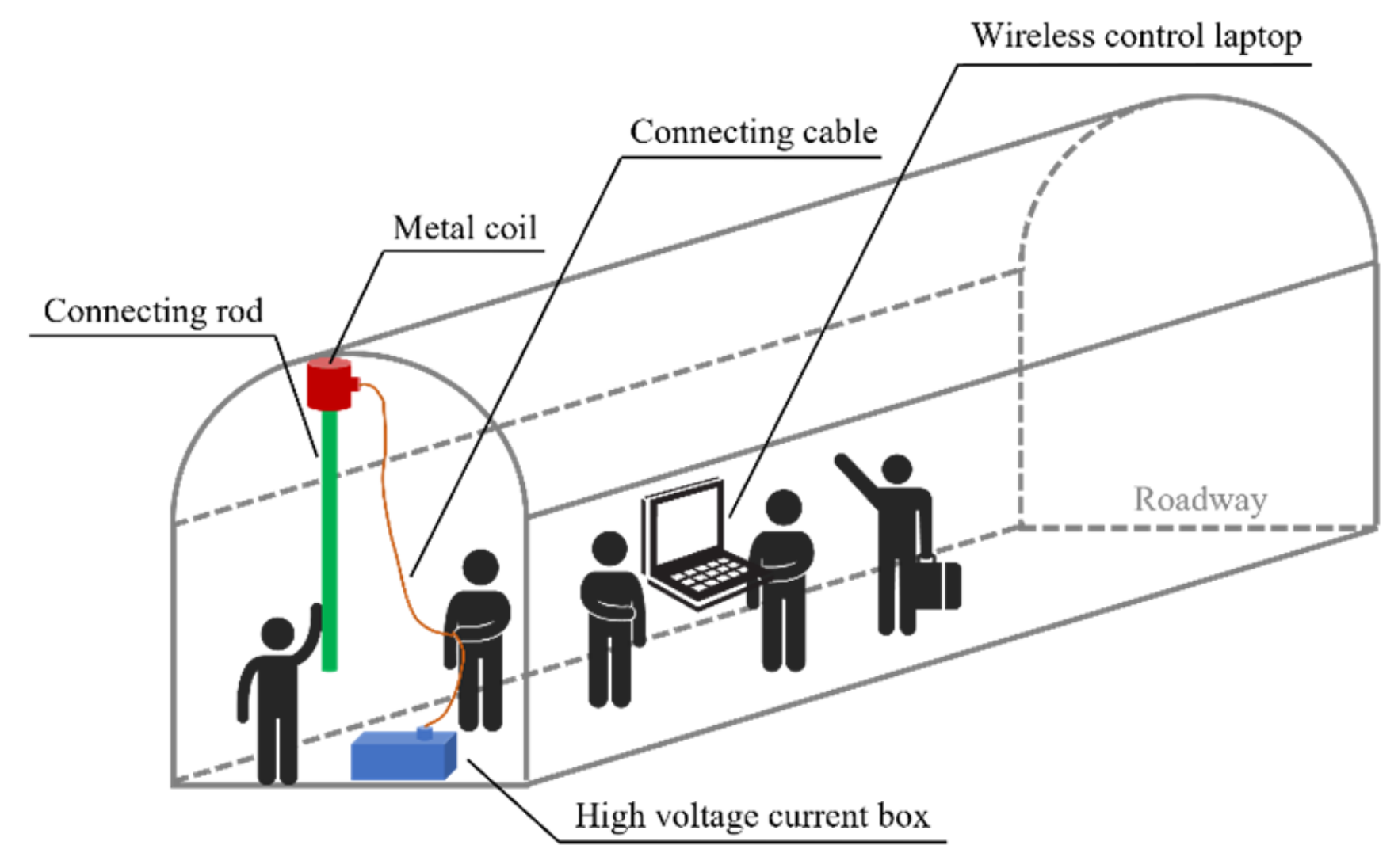
It is necessary to lift the connecting rod and place the metal coil on the measuring point when detecting. The current of the metal coil comes from the high-voltage current box, and the data are transmitted wirelessly to a wireless control notebook.
Figure 2 shows the principle of OCTEM. In this method, the parallel co-axial, same-size forward transmitting coil, and reverse transmitting coil are passed with equal and opposite current I. The receiving coil is placed between the two transmitting coils and receives the primary field generated by the dual coils with a vertical magnetic field of 0. The purpose of eliminating the mutual inductance phenomenon and the detection blind zone can be achieved [40].
The trend of the induced electric potential over time was directly measured using OCTEM, and the OCTEM decay curves of each detection line were plotted in double logarithmic coordinates, as shown in Figure 3. Among them, the “jitter jump” phenomenon of the decay curve appears at approximately 900 ms in line 1, which comes from the interference of the equipment at the working site [13]. In addition to the “jitter jump” phenomenon of line 1, the decay curve of each line tends to be smooth, indicating that the noise is weak and meets the detection requirements [27].
2.2. Detection Area and Test Scheme
The Tongkeng mining area is the research object of this study. The Tongkeng mine used many caving methods and open stope methods in the early days, forming many difficult-to-mine sections and residual ore bodies, such as loose and broken and filling overlapping areas. Under frequent ground pressure activities, collapse zones, and broken ore pillars appeared on a large scale [43]. Although most of the subsequent filling work has been carried out in recent years, many empty areas exist due to the inability to connect the top due to water secretion and settlement of the filling body. Local sections had the threat of caving or collapse, and there is a significant hidden danger to mine safety production. Therefore, in order to ensure the development of safety work, it is necessary to detect and analyze the unfavorable geological bodies of the Tongkeng mine. In order to ensure safe mining, some areas where safety cannot be determined were marked, and several survey lines were planned to detect their geological manifestations. Among them, the four survey lines arranged at the T5-1 stope at mine level 386 have the widest detection coverage and the most obvious resistivity variation characteristics, so the detection results of this stope were selected for the study.
The scene of this detection is the T5-1 stope at level 386 in the Guangxi Tongkeng mining area, which has four detection lines (Figure 4). Among them, lines 1, 2, and 3 are semicircular, starting from the direction of the bottom plate on one side of the roadway, collecting data every 30° and seven times in total. Line 4 is straight, placing the metal coil on the top plate, collecting data every 2 m and five times in total. Generally, the measuring points of the semicircular line are arranged on the semicircular section of the roadway, and the geological conditions in the semicircular area with a radius of 100 m can be obtained. The measuring point of the straight line is usually arranged on the roof or bottom of the roadway, and the geological condition in the rectangular area from the detection line to the square 100 m below the detection line can be obtained.
2.3. OCTEM-PHA Analysis Process
The distribution of hazard levels for the PHA method is shown in Table 1.
The inversion maps generated by OCTEM detection reflect the location, scale, and water richness degree of the apparent resistivity anomaly area in the detection area, reflecting the type and specific location of the risk factors existing in the corresponding area, which can be used as the risk factors in the PHA method and to start the PHA analysis. This study combines OCTEM detection in the field of geological remote sensing with the PHA method in the field of safety science and proposes the OCTEM-PHA analysis process. The flow chart is shown in Figure 5.
Using the process shown in Figure 5, it is helpful to carry out comprehensive hazard identification for the hidden danger areas detected by geophysical exploration, analyze the potential risks of various bad geological conditions, determine the hazard level, and develop countermeasures.
3. OCTEM Detection Results Analysis
3.1. Comparison of OCTEM Inversion Results and Profiles
In this study, the detection area is at level 386–486, and the rock types in the detection area from the bottom to the top include the Luofu Formation marl mudstone (), Liujiang Formation siliceous rock (), Wuzhishan Formation wide-banded limestone (), and Wuzhishan Formation fine-banded limestone (), as shown in Figure 6. In recent years, researchers have launched resistivity studies of the Dachang mining area in Guangxi. Wang Zhong et al. [44] measured the resistivity of rock samples from the Dachang mining area, and the resistivity of the surrounding rocks (limestone and siliceous rocks) within the mine was greater than n × 1000 Ω·m. Wei Mingxun et al. [45] summarized the data from a mining area in the northwest of Guangxi and concluded that the resistivity of mudstone in the region varies from 68 to 99,100 Ω·m (average resistivity of 682 Ω·m), the marl resistivity varies from 82 to 1000 Ω·m (average resistivity of 466 Ω·m), the siliceous rock resistivity varies from 169 to 15,800 Ω·m (average resistivity of 7600 Ω·m), and the limestone resistivity varies from 570 to 722,900 Ω·m (average resistivity of 1970 Ω·m). Yang Kangkang [46] combined the previous results and the drilling results of the tailings reservoir in Lutang, Dachang Town, Nandan County, Guangxi Province. Additionally, they concluded that the resistivity of marl and mudstone is n × 10–1000 Ω·m, and the resistivity of limestone is greater than 1000 Ω·m. Due to differences in equipment, testing time, and environmental variability, the resistivity of rocks greatly varies. However, simultaneously, the same area using the same equipment detection inversion results will not show resistivity’s “sudden change” (resistivity suddenly increased or suddenly decreased). The reason for this situation is the existence of unfavorable geological bodies. When the detection area is a water-filled fissure or water-filled goaf, the resistivity decreases. On the other hand, the resistivity increases when the detection area is an air-filled fissure or air-filled goaf [23,26,47].
Figure 7, Figure 8, Figure 9 and Figure 10 show the OCTEM inversion results and profiles of detection lines 1–4 in the T5-1 stope at level 386. The inversion results reflect the detection area’s high- and low-resistance characteristics, and the profiles visually reflect the structures corresponding to the apparent resistivity anomaly area.
Figure 7a shows the inversion results of line 1. The result shows an extensive range of low-resistance values with apparent resistivity of less than 600 Ω·m. The horizontal range is 58 m to the left of the line and 30 m to the right, and the vertical range is the height of the line to 70 m above the line. In this low-resistance area, there are three low-resistance anomaly areas with apparent resistivity less than 280 Ω·m. In the triangle low-resistance abnormal area A, the horizontal range of A is 14–44 m to the left of the line, and the vertical range is the height of the line to 22 m above the line. In the low-resistance abnormal area B, the horizontal range of B is 14 m to the left of the line and 8 m to the right, and the vertical range is the height of the line to 30 m above the line. In the low-resistance abnormal area C, the horizontal range of C is 26 m to the left of the line and 5 m to the right, and the vertical range is 28–46 m above the line. Moreover, there is a high-resistance abnormal area D with an apparent resistivity of 920 Ω·m. Finally, the horizontal range of D is 56–72 m to the right of the line, and the vertical range is the height of the line to 12 m above the line.
Figure 7b shows a profile of the detection area of line 1. The figure shows that the low-resistance value area corresponds to the T502 waste rock filling area, T502 caving area, 203# panel pillar caving area, R3 caving area, R3 waste rock filling area, roadways, and part of the structureless area (located at levels 418–428 and levels 440–455). Among the low-resistivity areas, the profile distribution of the three areas with lower resistivity is as follows. Area A mainly corresponds to the T502 caving area, the T502 waste rock filling area, and the roadways. Area B mainly corresponds to the 203# panel pillar caving area. Area C corresponds to the structureless area at the 418–428 level, the T502 waste rock filling area, and the 203# panel pillar caving area. Area D, with a higher resistivity, corresponds to the 92# pillar group caving area and the structureless area at the 386–392 level.
Figure 8a shows the inversion results of line 2. The result shows an extensive range of low-resistance values with an apparent resistivity of less than 600 Ω·m. The horizontal range is 75 m to the left of the line and 44 m to the right, and the vertical range is the height of the line to 64 m above the line. In this low-resistance area, there are three resistance anomaly areas: Ovel high-resistance abnormal area E with apparent resistivity of approximately 680 Ω·m, the horizontal range of E is 6–22 m to the left of the line, and the vertical range is 4–16 m above the line; Ovel low-resistance abnormal area F with an apparent resistivity of 200 Ω·m, the horizontal range of F is 10 m to the left of the line and 8 m to the right, and the vertical range is 18–40 m above the line; and high-resistance abnormal area G with an apparent resistivity of 680 Ω·m, the horizontal range of G is 4–16 m to the right of the line, and the vertical range is the height of the line to 18 m above the line. There is a low-resistance abnormal area H with an apparent resistivity of 600 Ω·m, the horizontal range of H is 62–70 m to the right of the line, and the vertical range is the height of the line to 6 m above the line.
Figure 8b illustrates a profile of the detection area of line 2. The figure shows that the low-resistance value area corresponds to the T501 caving area, 203# panel pillar caving area, 92# pillar group caving area, roadways, and part of the structureless area (located at levels 386–428 and levels 440–455). Among the low-resistivity areas, the profile distribution of the three resistivity anomaly areas is as follows. The E area with a relatively high resistivity corresponds to the 203# panel pillar caving area; the F area with a relatively low resistivity corresponds to the 203# panel pillar caving area and the structureless area at the 418–428 level; and the G area with a relatively high resistivity corresponds to the 92# pillar group caving area, roadways, and the structureless area at the 386–392 level. Area H, with low resistivity, corresponds to the structureless area at the 386–392 level.
Figure 9a shows the inversion results of line 3. The result shows that for low-resistance abnormal area I with an apparent resistivity of approximately 520 Ω·m, the horizontal range of area I is 22–30, 42–48, and 65–80 m to the left of the line. In Ovel high-resistance abnormal area J with apparent resistivity of approximately 1000 Ω·m, the horizontal range of J is 12–38 m to the left of the line, and the vertical range is 10–30 m above the line. In low-resistance abnormal area K with apparent resistivity of approximately 440 Ω·m, the horizontal range of K is 13 m to the left of the line and 32 m to the right, and the vertical range is the height of the line to 65 m above the line. In high-resistance abnormal area L with apparent resistivity of more than 1000Ω·m, the horizontal range of L is 56–94 m to the right of the line, and the vertical range is the height of the line to 40 m above the line.
Figure 9b shows a profile of the detection area of line 3. The figure shows that area I, with low resistivity, corresponds to roadways at the 386 level. Area J, with high resistivity, corresponds to the T501 caving area and the structureless area at the 392–418 level. Area K, with low resistivity, corresponds to the T501 caving area and the structureless area at the 418–428 level. Area L, with high resistivity, corresponds to the T306 waste rock filling area, R3 filling area, 14# caving area, roadways at the 386 level, and the structureless area at the 386–405 level.
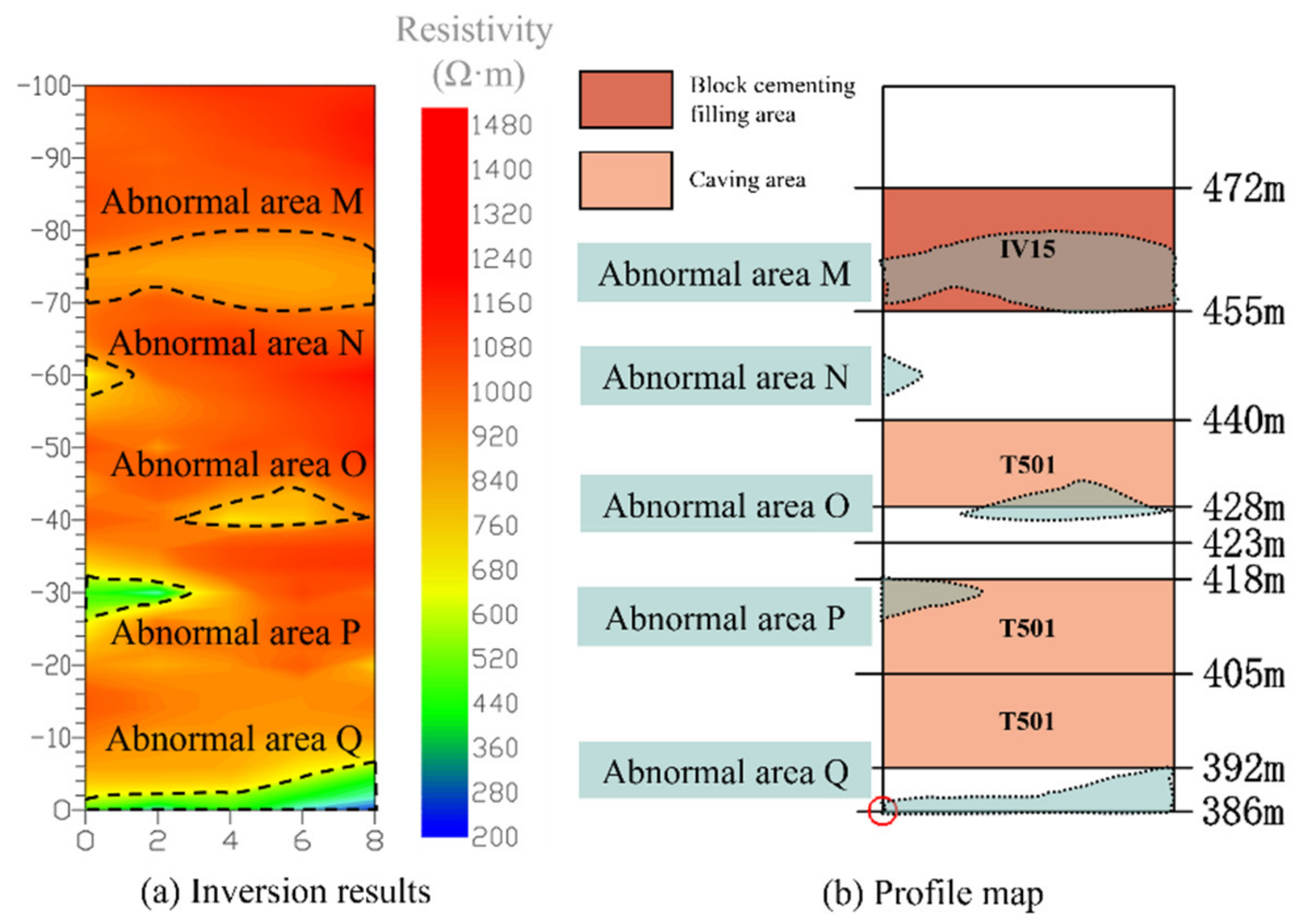
Figure 10a shows the inversion results of line 4, which is a straight line with one detection point every 2 m and a total of five detection points. The result shows that there is a low-resistance abnormal area M with apparent resistivity of approximately 920 Ω·m at 70–80 m above detection points 1–5. There is a low-resistance abnormal area N with apparent resistivity of 680 Ω·m at 58–62 m above detection points 1–2. Moreover, there is a low-resistance abnormal area O with apparent resistivity of 680 Ω·m at 40–466 m above detection points 2–5. Additionally, there is a low-resistance abnormal area P with apparent resistivity of 440 Ω·m at 58–62 m above detection points 1–3. Finally, there is a low-resistance abnormal area Q with apparent resistivity less than 440 Ω·m at the height of the line to 7 m above the line.
Figure 10b is a profile of the detection area of line 4. The figure shows that the M area with low resistivity corresponds to the IV15 block cementing filling area. Area N with low resistivity corresponds to the structureless area at the 440–455 level. Area O with low resistivity corresponds to the structureless area at the 423–428 level and T501 caving area. Area P with low resistivity corresponds to the T501 caving area. Area Q with low resistivity corresponds to the structureless area at the 386–392 level.
3.2. Analysis of Resistivity Anomaly Areas
The profiles were coupled and analyzed with the OCTEM inversion maps with marked anomalous regions and discussed as follows.
Line 1. As shown in Figure 7, among the known structures, some areas contain more water and should be focused on, such as the T502 waste rock filling area, T502 caving area, 203# panel pillar caving area, R3 caving area, and R3 waste rock filling area. The water content of the rock body is high in the area, from 56 m to the left of the line to 30 m to the right. There is a risk of water seepage and hydrops in the nearby roadways. The structural body of the 92# pillar group caving area at the 392 level is loose. Among the unknown structures, there may be a water-filled fissure or water-filled goaf in an area that ranges from the left (30 m) to the right (30 m) of the line, and the vertical range is the 440–455 level. There may be a water-filled fissure or water-filled goaf in an area that ranges from the left (50 m) to the right (30 m) of the line, and the vertical range is the 418–428 level. There may be a loose structure or air-filled goaf on the right (56–72 m) of the line, and the vertical range is the 386–392 level.
Line 2. As shown in Figure 8, among the known structures, including the T501 caving area, 203# panel pillar caving area, and 92# pillar group caving area with high water content, more attention should be paid to the water content in the 203# panel pillar caving area at the 405–418 level. The water content of the rock body is high in the area, from 70 m to the left of the line to 40 m to the right, and there is a risk of water seepage and hydrops in the nearby roadways. Among the unknown structures, there may be water-filled fissures or water-filled goaf in an area that ranges from the left (60 m) to the right (30 m) of the line, and the vertical range is the 418–428 level. There may be a water-filled fissure or water-filled goaf on the left 40–70 m of the line, and the vertical range is the 392–418 level. There may be a water-filled fissure or water-filled goaf on the right 62–70 m of the line.
Line 3. As shown in Figure 9, among the known structures, the structural body of the T501 caving area is loose, and the caving area contains an extensive range of water; the structural bodies of the T306 waste rock filling area, R3 waste rock filling area, and 14# caving area are loose. The water content of the rock body is high on the left 22–80 m of the line, and there is a risk of water seepage and hydrops in the nearby roadways. Among the unknown structures, there may be a water-filled fissure or water-filled goaf on the left 20–38 m of the line, and the vertical range is the 392–418 level. There may be a water-filled fissure or water-filled goaf on the right 10–18 m of the line, and the vertical range is the 418–428 level. There may be loose structure or air-filled goaf on the right 56–90 m of the line, and the vertical range is the 418–428 level. There may be loose structure or air-filled goaf on the right 60–95 m of the line, and the vertical range is the 386–405 level.
Line 4. As shown in Figure 10, among the known structures, including the IV15 block cementing filling area and the T501 caving area with high water content, more attention should be paid to the water content in the T501 caving area. Among the unknown structures, there may be water-filled fissures or water-filled goaf at the 386–392, 423–428, and 440–455 levels above the detection line. Among the anomalous areas previously mentioned, some of them are detected in more than one line (e.g., 203# panel pillar caving area, R3 waste rock filling area, 92# pillar group caving area, T501 caving area, and roadways at the 386–392 level). The detection results among the lines verify each other, indicating that the inversion results obtained by the OCTEM method show good correspondence to both high-resistance and low-resistance anomalies, and the detection results are reliable.
3.3. PHA Analysis
The detection results of the 1–4 detection lines were mainly divided into risk factors in known structural areas and risk factors in unknown structural areas.
(1) Known structural area (i.e., the caving or filling area or the roadways) already existed in the profile. The caving area or filling area may have either a high-resistance anomaly (loose structural body) or a low-resistance anomaly (water-filled). The surrounding rock of the roadways contains water, and there are risks of water seepage and accumulation.
(2) Unknown structure area (i.e., the area where the corresponding structure does not exist on the profile) contains both high-resistance anomaly (loose structure or air-filled goaf) and low-resistance anomaly (water-filled fissure or water-filled goaf).
The risk factors detected by the OCTEM can be analyzed by the PHA. On the basis of the traditional PHA table, the spatial position and line number of the above risk factors were summarized, which is convenient to reflect the specific location of each risk factor more intuitively. The possible trigger events and consequences of each risk factor were analyzed. According to the risk level distribution in Table 1, the risk levels were determined according to the principle of “no loss as level Ⅰ, no casualties as level Ⅱ, casualties as level Ⅲ, destructive casualties as level Ⅳ”, and finally, the consequence were listed. The PHA analysis is shown in Table 2.
It was confirmed on site that there was no overhang and a large loose void area formed by the overlying rock layer in the summarized anomaly area, as shown in Table 2. However, the corresponding high-resistance anomaly areas are all loose structures, the overlying loose rock body has a tendency to further loose movement toward the caving stope, and there is uneven subsidence due to the influence of the early mass adoption of the caving method and the continuous influence of mining activities. Due to the influence of local precipitation, the corresponding low-resistance areas all have a certain degree of water accumulation. Based on the PHA analysis results and the results confirmed on-site, the following safety management suggestions are proposed.
- (1)
- The caving mining area must be further optimized to realize balanced mining. The unsafe factors of excessive local settlement of rock layers must be reduced due to unbalanced mining. Then, the draw control must be strengthened, the uniformity of ore release must be improved, and the local overhang brought by uneven ore output must be reduced.
- (2)
- The treatment of groundwater and surface water must be improved. The Tongkeng deposit is filled with water due to fissure water and atmospheric precipitation. Due to the high local precipitation, the detection results show that the resistance anomaly area is mainly a water-rich, low-resistance area. Thus, the water treatment in the water-rich area should be strengthened to reduce the impact of water on the mine during underground mining.
- (3)
- The comparative analysis must be increased with the following detection results, the caving and filling mining interface must be strengthened, and technical reserves and planning must be proposed.
4. Conclusions
In this study, the safety analysis of OCTEM-PHA was carried out by taking the Tongkeng Mine in Guangxi as an example. In the process of analysis, the portable geological remote sensing equipment was used to carry out OCTEM detection of the mine’s 386 level T5-1 stope and created the inversion maps. Then, we combined the geological data of the mine to analyze the apparent resistivity abnormal area, used the plan from the different elevations of the mine to plot profiles, and coupled the profiles with the inversion maps. Moreover, we analyzed the five types of risk factors existing in the mine. Using the elevation plan of the mine to draw a profile map and coupling the profile map with the inversion map of the TEM, we analyzed five types of risk factors existing in the mine. The PHA method was used to analyze the five types of risk factors, predict the consequences of accidents, and formulate countermeasures. The following research results were achieved.
(1) The OCTEM-PHA analysis process is proposed by combining the characteristics and correlation of the OCTEM method and the PHA safety analysis method. This process is helpful for the comprehensive identification of danger sources, analysis of potential risks of various adverse geological conditions, determination of risk levels, and formulation of countermeasures. Moreover, this method has practical feasibility.
(2) Opposing-coil TEM (OCTEM) has an excellent response to both high- and low-resistance anomalies in engineering practice and can effectively detect loose areas of mine structures, water-filled areas, and goaf. Using the elevation plan of the mine to draw a profile map and coupling the profile map with the inversion map of TEM can directly show the structure of the resistance anomaly area. It is helpful to further analyze the reason for abnormal resistivity and provide the corresponding safety technical measures.
(3) Using PHA analysis, safety countermeasures are provided for the five types of risk factors existing in the case mine. In the case confirmed on site, there is no hanging and large loose goaf formed by overlying strata in the mine. However, due to the continuous influence of mining activities and the factors of local fissure water and precipitation, loose rock mass and water-bearing rock mass exist on site. It is suggested to optimize the caving mining area further to achieve balanced mining, improve groundwater and surface water treatment, and increase the comparative analysis with subsequent detection results.
Author Contributions
Conceptualization, T.Z. (Tan Zhou) and J.H.; methodology, T.Z. (Tan Zhou); software, T.Z. (Tao Zhu); validation, T.Z. (Tao Zhu), J.H., G.W. and T.Z. (Tan Zhou); formal analysis, T.Z. (Tao Zhu) and J.H.; investigation, G.W. and T.Z. (Tan Zhou); resources, J.H.; data curation, T.Z. (Tao Zhu) and T.Z. (Tan Zhou); writing—original draft preparation, T.Z. (Tao Zhu); writing—review and editing, J.H., G.W. and T.Z. (Tan Zhou); visualization, T.Z. (Tao Zhu); supervision, J.H.; project administration, G.W.; funding acquisition, J.H. All authors have read and agreed to the published version of the manuscript.
Funding
This work was supported by the National Natural Science Foundation of China (grant number 52274182).
Data Availability Statement
The data that support the findings of this study are available from the corresponding author upon reasonable request.
Acknowledgments
Thanks to Tongkeng Mine for providing the detection site.
Conflicts of Interest
The authors declare that they have no conflict of interest.
References
- Ranjith, P.G.; Zhao, J.; Ju, M.H.; De Silva, R.V.; Rathnaweera, T.; Bandara, A.K. Opportunities and Challenges in Deep Mining: A Brief Review. Engineering 2017, 3, 546–551. [Google Scholar] [CrossRef]
- Wang, X.; Huang, F.; Fan, X.; Shahabi, H.; Shirzadi, A.; Bian, H.; Ma, X.; Lei, X.; Chen, W. Landslide susceptibility modeling based on remote sensing data and data mining techniques. Environ. Earth Sci. 2022, 81, 1–19. [Google Scholar] [CrossRef]
- Li, W.; Fan, X.; Huang, F.; Chen, W.; Hong, H.; Huang, J.; Guo, Z. Uncertainties Analysis of Collapse Susceptibility Prediction Based on Remote Sensing and GIS: Influences of Different Data-Based Models and Connections between Collapses and Environmental Factors. Remote Sens. 2020, 12, 4134. [Google Scholar] [CrossRef]
- Fang, Z.H.; Wang, L.G.; Xiong, Z.Y. Mining Disturbance Analysis in Metal Mine Based on Micromine-FLAC3D Coupling Technology. J. Min. Saf. Eng. 2012, 29, 870–875. (In Chinese) [Google Scholar]
- Zhang, G.H.; Jiao, Y.Y.; Wang, H.; Cheng, Y.; Chen, L.-B. On the Mechanism of Inrush Hazards hen Denghuozhai Tunnel Passing Through Granite Contact Zone. Tunn. Undergr. Space Technol. 2017, 68, 174–186. [Google Scholar] [CrossRef]
- Liu, X.T.; Chen, C.X.; Xia, K.Z.; Zheng, X.W.; Wang, T.L.; Yuan, J.H. Investigation of the Time-Dependent Strata Movement Behaviour Caused by Caving Method. Rock Soil Mech. 2023, 44, 563–576. (In Chinese) [Google Scholar] [CrossRef]
- Xia, K.; Chen, C.; Wang, T.; Zheng, Y.; Wang, Y. Estimating the Geological Strength Index and Disturbance Factor in the Hoek-Brown Criterion Using the Acoustic Wave Velocity in the Rock Mass. Eng. Geol. 2022, 306, 106745. [Google Scholar] [CrossRef]
- Song, X.; Chen, C.; Xia, K.; Yang, K.; Chen, S.; Liu, X. Analysis of the Surface Deformation Characteristics and Strata Movement Mechanism in the Main Shaft Area of Chengchao Iron Mine. Environ. Earth Sci. 2018, 77, 335. [Google Scholar] [CrossRef]
- Chang, Z.; Du, Z.; Zhang, F.; Huang, F.; Chen, J.; Li, W.; Guo, Z. Landslide Susceptibility Prediction Based on Remote Sensing Images and GIS: Comparisons of Supervised and Unsupervised Machine Learning Models. Remote Sens. 2020, 12, 502. [Google Scholar] [CrossRef] [Green Version]
- Wang, L.; Liu, Y.; Yin, C.; Su, Y.; Ren, X.; Zhang, B. Three-Dimensional Dual-Mesh Inversions for Sparse Surface-to-Borehole TEM Data. Remote Sens. 2023, 15, 1845. [Google Scholar] [CrossRef]
- Ren, H.; Lei, D.; Wang, Z.; Fu, C. A Mesh Mapping-Based Cooperative Inversion Strategy for Airborne Transient Electromagnetic and Magnetic Methods. Remote Sens. 2023, 15, 125. [Google Scholar] [CrossRef]
- Cao, B.; Wang, J.; Du, H.; Tao, Y.; Liu, G. Research on Comprehensive Detection and Visualize of Hidden Cavity Goaf. Sci. Rep. 2022, 12, 1–21. [Google Scholar] [CrossRef]
- Luo, X.; Gong, S.; Huo, Z.; Li, H.; Ding, X. Application of Comprehensive Geophysical Prospecting Method in the Exploration of Coal Mined-Out Areas. Adv. Civ. Eng. 2019, 2019, 1–17. [Google Scholar] [CrossRef] [Green Version]
- Cao, J.; Sun, L.; Wu, C. Separation of DC Elecrical Method Anomaly by Using Multifractral Modelling. Fresenius Environ. Bull. 2022, 31, 11014–11019. [Google Scholar]
- Wang, P. Advanced Detection Technology of Ground-Borehole DC Resistivity Method. Earth Sci. 2023, 1–11. Available online: http://kns.cnki.net/kcms/detail/42.1874.p.20221005.1221.004.html (accessed on 22 April 2023). (In Chinese).
- Zhou, G.Q.; Wang, Y.F.; Chen, X.H.; Yue, M.X.; Zhai, F.Q.; Yang, X.D.; Wu, X.P.; Cao, Y.; Cui, Y. Research on Forward Modeling of “Triangular Cone” Type Direct Current Method For Heading Detection. J. China Coal Soc. 2022, 47, 3015–3023. (In Chinese) [Google Scholar] [CrossRef]
- Hao, L.; Li, N.; Xu, X.; Zhang, Q.; Chen, L.; Sun, F. Detecting Goaf Ahead of the Mine Tunnel Using SAP: A Case Study in Iron Mine, China. Geotech. Geol. Eng. 2022, 40, 883–897. [Google Scholar] [CrossRef]
- Wei, H.X.; Cha, W.F.; Feng, C.L. Analysis of Characteristics of Seismic Section in Goaf Area. Prog. Geophys. 2014, 29, 1808–1814. (In Chinese) [Google Scholar]
- Ismail, A.; Abdelnaby, A.; Larson, T. High-resolution P- and S-wave Seismic Reflection Followed by Engineering Modeling for Geotechnical Site Characterization in Southern Illinois. J. Environ. Eng. Geophys. 2017, 22, 375–384. [Google Scholar] [CrossRef]
- Zhang, M.; Feng, X.; Bano, M.; Xing, H.; Wang, T.; Liang, W.; Zhou, H.; Dong, Z.; An, Y.; Zhang, Y. Review of Ground Penetrating Radar Applications for Water Dynamics Studies in Unsaturated Zone. Remote Sens. 2022, 14, 5993. [Google Scholar] [CrossRef]
- Hou, F.; Rui, X.; Fan, X.; Zhang, H. Review of GPR Activities in Civil Infrastructures: Data Analysis and Applications. Remote Sens. 2022, 14, 5972. [Google Scholar] [CrossRef]
- Xue, G.; Chen, W.; Cheng, J.; Liu, S.; Yu, J.; Lei, K.; Guo, W.; Feng, X. A Review of Electrical and Electromagnetic Methods for Coal Mine Exploration in China. IEEE Access 2019, 7, 177332–177341. [Google Scholar] [CrossRef]
- Xue, G.Q.; Yan, Y.J.; Cheng, J.L. Researches on Detection of 3-D Underground Cave Based on TEM Technique. Environ. Earth Sci. 2011, 64, 425–430. [Google Scholar] [CrossRef]
- Danielsen, J.E.; Auken, E.; Jorgensen, F.; Sondergaard, V.; Sorensen, K.I. The Application of the Transient Electromagnetic Method in Hydrogeophysical Surveys. J. Appl. Geophys. 2003, 53, 181–198. [Google Scholar] [CrossRef]
- Wu, J.; Zhi, Q.; Deng, X.; Wang, X.; Chen, X.; Zhao, Y.; Huang, Y. Deep Gold Exploration with SQUID TEM in the Qingchengzi Orefield, Eastern Liaoning, Northeast China. Minerals 2022, 12, 102. [Google Scholar] [CrossRef]
- Yu, C.; Liu, X.; Liu, J.; Li, E.; Yue, P.; Yan, S. Application of Transient Electromagnetic Method for Investigating the Water-Enriched Mined-Out Area. Appl. Sci. 2018, 8, 1800. [Google Scholar] [CrossRef] [Green Version]
- Chang, J.; Su, B.; Malekian, R.; Xing, X. Detection of Water-Filled Mining Goaf Using Mining Transient Electromagnetic Method. Ieee Trans. Ind. Inform. 2020, 16, 2977–2984. [Google Scholar] [CrossRef]
- Xi, Z.Z.; Long, X.; Zhou, S.; Huang, L.; Song, G.; Hou, H.T.; Wang, L. Opposing Coils Transient Electromagnetic Method for Shallow Subsurface Detection. Chin. J. Geophys. 2016, 59, 3428–3435. (In Chinese) [Google Scholar]
- Yang, G.; Xie, C.; Wu, T.; Wu, X.; Zhang, Y.; Wang, W.; Liu, G. Detection of Permafrost in Shallow Bedrock Areas with the Opposing Coils Transient Electromagnetic Method. Front. Environ. Sci. 2022, 10, 909848. [Google Scholar] [CrossRef]
- Wen, L.; Cheng, J.; Huang, S.; Zhou, J.; Han, Y.; Li, F.; Zhao, J. Review of Geophysical Exploration on Mined-out Areas and Water Abundance. J. Environ. Eng. Geophys. 2019, 24, 129–143. [Google Scholar] [CrossRef]
- Xu, Q.; Xu, K.; Li, L.; Yao, X. Assessment of Petrochemical Enterprise Using the Cloud Model, PHA-LOPA and the Bow-Tie Model. R. Soc. Open Sci. 2018, 5, 180212. [Google Scholar] [CrossRef] [Green Version]
- Yan, F.; Xu, K. Methodology and Case Study of Quantitative Preliminary Hazard Analysis Based on Cloud Model. J. Loss Prev. Process Ind. 2019, 60, 116–124. [Google Scholar] [CrossRef]
- Hfaiedh, N.; Kabiche, S.; Delescluse, C.; Balde, I.-B.; Merlin, S.; Carret, S.; de Pontual, L.; Fontan, J.-E.; Schlatter, J. Performing a Preliminary Hazard Analysis Applied to Administration of Injectable Drugs to Infants. J. Eval. Clin. Pract. 2017, 23, 875–881. [Google Scholar] [CrossRef]
- La Fata, C.M.; Giallanza, A.; Micale, R.; La Scalia, G. Improved FMECA for Effective Risk Management Decision Making by Failure Modes Classification under Uncertainty. Eng. Fail. Anal. 2022, 135, 106163. [Google Scholar] [CrossRef]
- Shen, G.-X.; Sun, S.-G.; Zhang, Y.-Z.; Wang, Z.-Q.; Chen, B.-K.; Ma, C. System Failure Analysis Based on DEMATEL-ISM and FMECA. J. Cent. South Univ. 2014, 21, 4518–4525. [Google Scholar] [CrossRef]
- Dunjo, J.; Fthenakis, V.; Vilchez, J.A.; Arnaldos, J. Hazard and Operability (HAZOP) Analysis. A Literature Review. J. Hazard. Mater. 2010, 173, 19–32. [Google Scholar] [CrossRef]
- Li, W.; Sun, Y.; Cao, Q.; He, M.; Cui, Y. A Proactive Process Risk Assessment Approach Based on Job Hazard Analysis and Resilient Engineering. J. Loss Prev. Process Ind. 2019, 59, 54–62. [Google Scholar] [CrossRef]
- Ozfirat, M.K.; Ozkan, E.; Kahraman, B.; Sengun, B.; Yetkin, M.E. Integration of Fisk Matrix and Event Tree Analysis: A Natural Stone Plant Case. Sadhana-Acad. Proc. Eng. Sci. 2017, 42, 1741–1749. [Google Scholar] [CrossRef]
- Kabir, S. An Overview of Fault Tree Analysis and its Application in Model Based Dependability Analysis. Expert Syst. Appl. 2017, 77, 114–135. [Google Scholar] [CrossRef] [Green Version]
- Wang, L.; Dai, Y.F.; Liu, B.; Long, X.; Lin, J.; Chen, X.P. Research on Rapid Detection of Seawater Intrusion Based on Opposing-Coil Transient Electromagnetic Method. Prog. Geophys. 2023, 38, 1397–1407. (In Chinese) [Google Scholar]
- Cui, X.L. A Study on Detection of Goaf Water of Tianli-Tianxin Coal Mine Based on Transient Electromagnetic Method. IOP Conf. Ser. J. Phys. 2019, 1176, 062055. [Google Scholar] [CrossRef]
- Wu, G.; Yang, G.; Tan, H. Mapping Coalmine Goaf Using Transient Electromagnetic Method and High Density Resistivity Method in Ordos City, China. Geod. Geodyn. 2016, 7, 340–347. [Google Scholar] [CrossRef] [Green Version]
- Wang, H.X.; Chen, H.; Zhang, S.G.; Wan, C.C. In Situ Fragmentation Blasting Technology in Mining of High Stress Broken Ore Body. Nonferrous Met. Eng. 2015, 5, 8–12. (In Chinese) [Google Scholar]
- Wang, Z.; Zhang, X.L.; Luo, R.L.; Wang, Z.H. Abnormal Characteristic of TEM Response for Prospecting Depth and Margin Area of Tin Polymetallic Deposit in Dachang. J. Guilin Univ. Technol. 2009, 29, 303–309. (In Chinese) [Google Scholar]
- Wei, M.X.; Li, S.P.; Qi, J.; Huang, W.F.; Tao, Y.; Yang, C.F. Application of Magnetotelluric Sounding Method in the Survey and Evaluation of Shale Gas Resources in North Guangxi. Miner. Resour. Geol. 2022, 36, 614–621. (In Chinese) [Google Scholar] [CrossRef]
- Yang, K.K. Lutang Tailing Pond’s Karst Development Characteristics and Its Groundwater Environment Impact; Guilin University of Technology: Guilin, China, 2021. (In Chinese) [Google Scholar]
- Mu, Y.; Qiu, H.; Xu, H.; Li, J. Electromagnetic Response Characteristics Research on Mine Different Geological Body. IOP Conf. Ser. Earth Environ. Sci. 2019, 237, 062015. [Google Scholar]
- Zhang, G.H.; Wang, C.T.; Jiao, Y.Y.; Wang, H.; Chen, L.-B. Deposits Sources of Inrush Hazards for the Liangshan Tunnel Passing Through Deeply Buried Granite. Tunn. Undergr. Space Technol. 2019, 92, 103058. [Google Scholar] [CrossRef]
- Zhang, G.H.; Jiao, Y.Y.; Ma, C.X.; Wang, H.; Chen, L.-B.; Tang, Z.-C. Characteristics of Granite Contact Zone and Treatment Measures for Inrush Hazards During Tunnel Construction–A Case Study. Eng. Geol. 2018, 235, 64–80. [Google Scholar] [CrossRef]
Figure 2.
Schematic of the opposing-coil transient electromagnetic method (OCTEM).
Figure 3.
OCTEM decay curve of each detection line.

Figure 4.
Distribution of detection lines in T5-1 stope at level 386.
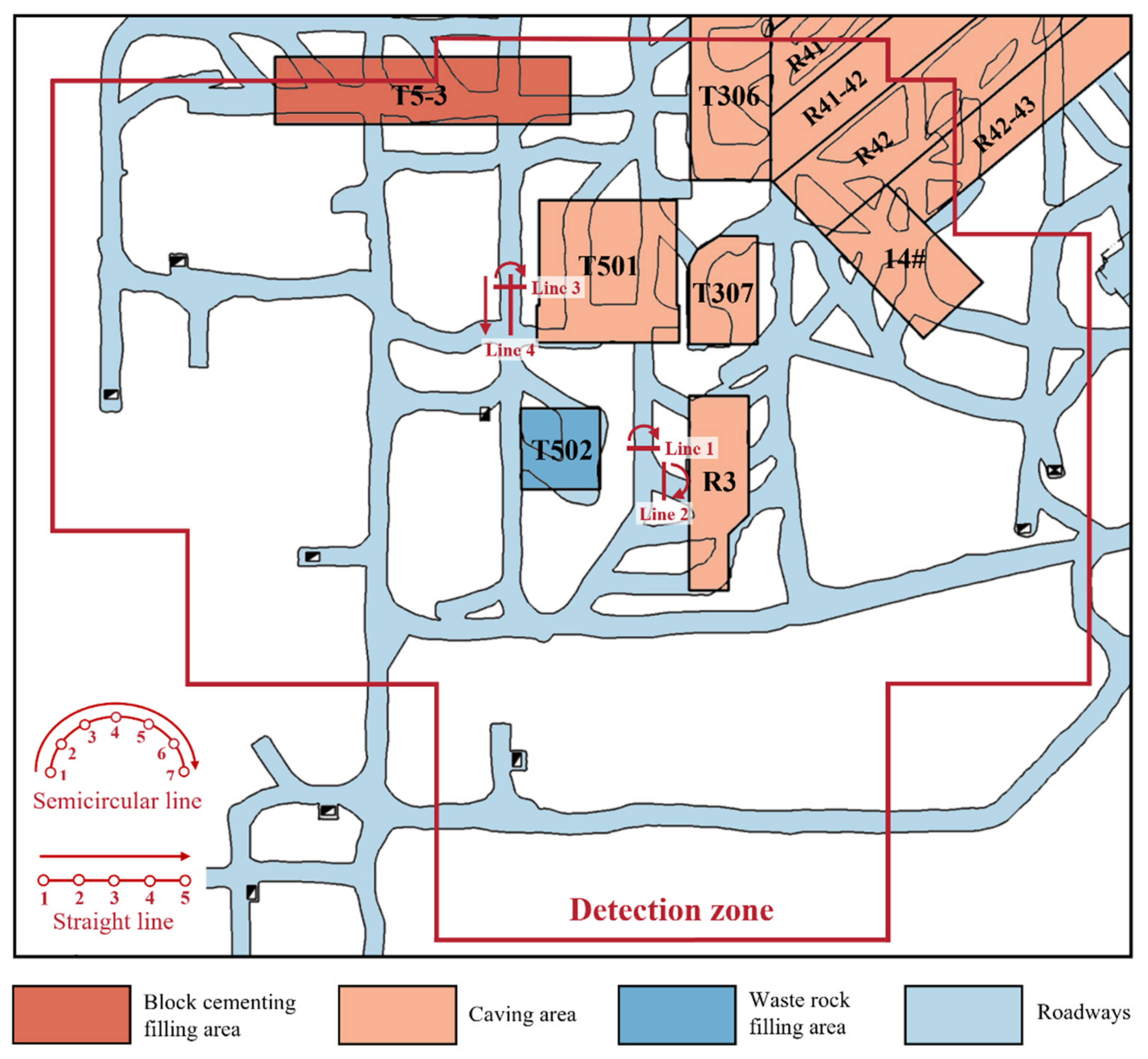
Figure 5.
OCTEM-PHA analysis process.
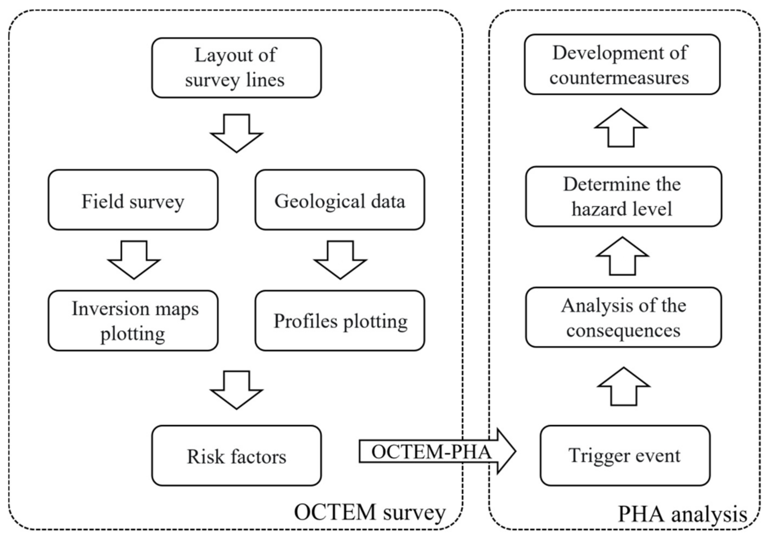
Figure 6.
Geological profile of the detection area.
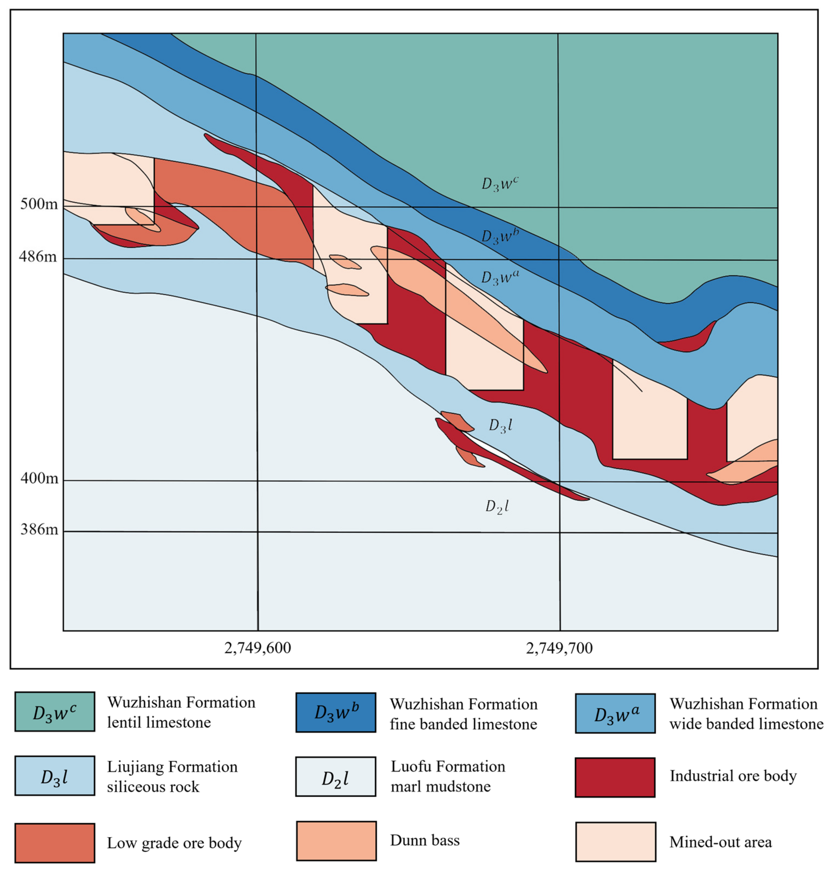
Figure 7.
Comparison of TEM inversion results and profile of line 1.

Figure 8.
Comparison of TEM inversion results and profile of line 2.
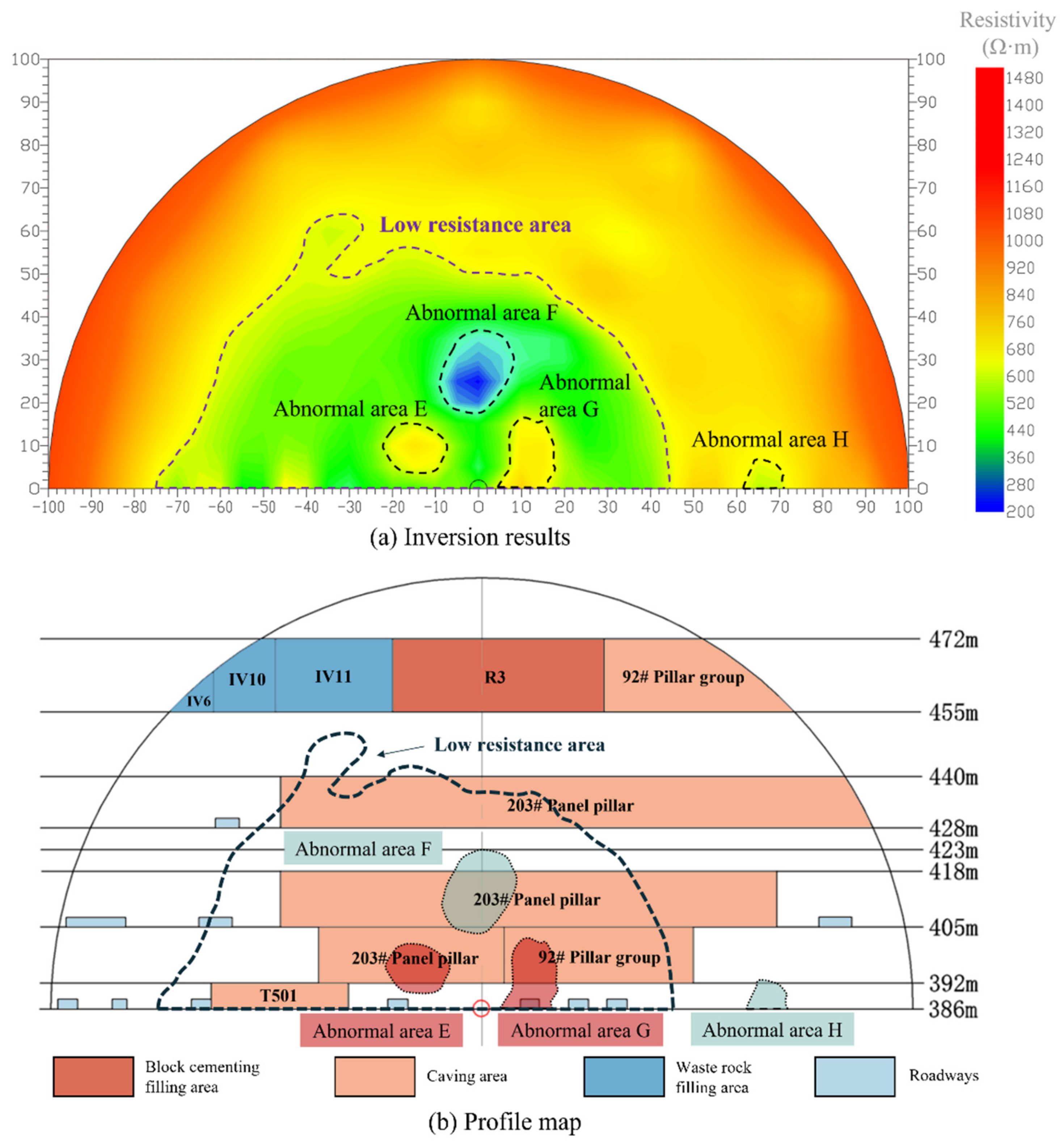
Figure 9.
Comparison of TEM inversion results and profile of line 3.

Figure 10.
Comparison of TEM inversion results and profile of line 4.

Table 1.
PHA risk level distribution.
| Level | Severity Level | Possible Consequences |
|---|---|---|
| Ⅰ | Safe | Does not cause injury or disease, no loss of system, negligible |
| Ⅱ | Marginal | On the verge of an accident that will not cause casualties and system damage for the time being but should be eliminated or controlled |
| Ⅲ | Dangerous | Will cause casualties and system damage, must take immediate measures to control |
| Ⅳ | Catastrophic | Destructive, can cause death or system obsolescence, must try to eliminate |
Table 2.
PHA analysis table for resistivity anomaly area.
| Risk Factor | Horizontal Range of Anomalous Area | Vertical Range of Anomalous Area (Level) | Trigger Event | Consequence | Risk Level | Countermeasure |
|---|---|---|---|---|---|---|
| Known caving areas or filling areas contains water | T502 filling area and caving area | 386–418; 428–440 |
|
|
|
|
| 203# panel pillar caving area | 392–418; 428–440 | |||||
| R3 filling area and caving area | 386–418; 428–440 | |||||
| 92# pillar group caving area | 392–405 | |||||
| T501 caving area | 386–418; 428–440 | |||||
| IV15 filling area | 455–472 | |||||
| Known caving areas or filling areas loose structure | 92# pillar group caving area | 392–405 | Ground pressure imbalance increases with mining operation disturbance. | Collapse, spalling and roof falling, or object attacks occur in the surrounding area. | Ⅲ | Organize special personnel with geological drilling equipment to check the caving area (or filling area) and verify the results of physical exploration; take measures such as hanging nets, anchor rods, and slurry spraying to reinforce. |
| T501 caving area | 386–418; 428–440 | |||||
| T306 filling area | 405–418 | |||||
| R3 filling area | 405–418 | |||||
| 14# caving area | 386–418 | |||||
| Surrounding rock of roadways contains water | Left 56 m to right 30 m of line 1 | 386–392 |
|
|
|
|
| Left 70 m to right 40 m of line 2 | 386–392 | |||||
| Left 22 m–80 m of line 3 | 386–392 | |||||
| Hidden water-filled fissure or water-filled goaf | Left 30 m to right 30 m of line 1 | 440–455 |
|
|
|
|
| Left 50 m to right 30 m of line 1 | 418–428 | |||||
| Left 60 m to right 30 m of line 2 | 418–428 | |||||
| Left 40 m–70 m of line 2 | 392–418 | |||||
| Right 62 m–70 m of line 2 | 386–392 | |||||
| Area above line 4 | 386–392; 423–428; 440–455 | |||||
| Hidden loose structure or air-filled goaf | Right 56 m–72 m of line 1 | 386–392 |
|
|
|
|
| Left 20 m–38 m of line 3 | 392–418 | |||||
| Right 10 m–18 m of line 3 | 418–428 | |||||
| Right 56 m–90 m of line 3 | 418–428 | |||||
| Right 60 m–95 m of line 3 | 386–405 |
Disclaimer/Publisher’s Note: The statements, opinions and data contained in all publications are solely those of the individual author(s) and contributor(s) and not of MDPI and/or the editor(s). MDPI and/or the editor(s) disclaim responsibility for any injury to people or property resulting from any ideas, methods, instructions or products referred to in the content. |
© 2023 by the authors. Licensee MDPI, Basel, Switzerland. This article is an open access article distributed under the terms and conditions of the Creative Commons Attribution (CC BY) license (https://creativecommons.org/licenses/by/4.0/).
Share and Cite
MDPI and ACS Style
Zhu, T.; Hu, J.; Wen, G.; Zhou, T. Research on Detection and Safety Analysis of Unfavorable Geological Bodies Based on OCTEM-PHA. Remote Sens. 2023, 15, 3888. https://doi.org/10.3390/rs15153888
AMA Style
Zhu T, Hu J, Wen G, Zhou T. Research on Detection and Safety Analysis of Unfavorable Geological Bodies Based on OCTEM-PHA. Remote Sensing. 2023; 15(15):3888. https://doi.org/10.3390/rs15153888
Chicago/Turabian StyleZhu, Tao, Jianhua Hu, Guanping Wen, and Tan Zhou. 2023. "Research on Detection and Safety Analysis of Unfavorable Geological Bodies Based on OCTEM-PHA" Remote Sensing 15, no. 15: 3888. https://doi.org/10.3390/rs15153888
Note that from the first issue of 2016, this journal uses article numbers instead of page numbers. See further details here.