


Radar Observation of the Lava Tubes on the Moon and Mars


1
Institute for Advance Study, Shenzhen University, Shenzhen 518060, China
2
Institute of Moon–Base Exploration and Observation, Shenzhen University, Shenzhen 518060, China
*
Author to whom correspondence should be addressed.
Remote Sens. 2023, 15(11), 2850; https://doi.org/10.3390/rs15112850
Submission received: 1 May 2023
/
Revised: 24 May 2023
/
Accepted: 25 May 2023
/
Published: 30 May 2023
(This article belongs to the Special Issue Ground Penetrating Radar (GPR) Applications in Earth, Moon and Planetary Exploration)
Abstract
:The detection of lava tubes beneath the surfaces of the Moon and Mars has been a popular research topic and challenge in planetary radar observation. In recent years, the Moon–based ground penetrating radar (GPR) carried by the Chinese Chang’e–3/–4 mission, the RIMFAX radar carried by the Mars mission Perseverance, and the RoSPR radar and MOSIR radar carried by China’s Tianwen–1 orbiter have extensively promoted the exploration of the underground space of extraterrestrial bodies, which is crucial for the future utilization and development of these spaces. This paper expounds on the principles, methods, and detection results of using GPR to detect lava tubes on the Moon and Mars. First, lava tubes’ formation mechanism and morphological characteristics are outlined, followed by an introduction to GPR’s working principles and classification. The advantages, disadvantages, and prospects of different types of radar in detecting the lava tubes are analyzed. Finally, the distribution of lava tubes on the Moon and Mars is briefly summarized, and the potential utilization of lava tubes is discussed. We believe that the GPR technique is an effective geophysical method for exploring the underground structures of the Moon and Mars, and the lava tubes beneath the surface of extraterrestrial bodies can provide important references for selecting future Moon and Mars bases.
1. Introduction
In recent years, the Moon and Mars have been popular celestial bodies for human deep space exploration. Over a hundred exploration missions have been conducted for the Moon and Mars [1,2,3]. In general, the exploration modes for the Moon and Mars can be divided into orbiter missions and in situ lander or rover missions. Significant scientific achievements have been made in the study of the shallow subsurface structure, material composition, terrain, and landforms of the Moon and Mars through these exploration modes [1,4,5,6,7]. However, despite the high–resolution and multi–spectral imaging of the surfaces of Mars and the Moon, as well as the sampling and analysis of their surfaces using rovers, we have limited knowledge of the potential existence and conditions of underground lava tubes. Lava tubes are tunnel–like structures within lava flows and can vary in diameter, length, and shape [8,9]. Due to the Moon and Mars both having low–gravity environments, the lava tubes on these celestial bodies can have volumes that are 1–3 orders of magnitude larger than those found on Earth [8].
Studying the internal structure of these lava tubes and their distribution in the shallow subsurface of celestial bodies has always been challenging. However, with the development of modern radar technology in the past 30 years, ground penetrating radar (GPR) have gradually become the most effective technology for investigating the subsurface structures of celestial bodies. This has been successfully applied in exploring the shallow subsurface of the Moon and Mars. For example, the Chang’e–3 and Chang’e–4 missions to the Moon carried Moon–based GPR, and the Mars exploration missions, Tianwen–1 and Perseverance, carried RoSPR and RIMFAX radar [7,10,11,12,13,14,15,16]. The GPR emits electromagnetic pulse signals from its transmitting antenna. These signals encounter different geological layers beneath the surfaces of celestial bodies and produce reflected echoes due to differences in dielectric constants. The echoes are received by the receiving antenna, providing information on various geological layers and underground structures [1,11,17]. By analyzing the electromagnetic characteristics of the radar echoes and underground structure information, it is hoped that we can locate the position of the lava tubes beneath the surfaces of the Moon and Mars, as well as obtain their physical morphology and size [18]. For example, based on Lunar Radar Sounder (LRS) data, Kaku et al. [19] provided the first evidence of intact buried lava tubes beneath the surface in the Marius Hills region of the Moon. Ding et al. [7] first reported the existence of a buried underground cavity structure with a height of approximately 3.1 m beneath the Chang’e–3 landing area using the Moon–based GPR onboard the Chang’e–3 rover. Due to the frequent volcanic activity and impact events that both the Moon and Mars experienced in their history [20,21,22], a large number of unobserved lava tubes and cavities are expected to exist beneath the surfaces of these celestial bodies [7,8,23]. These subsurface spaces can provide important references for selecting future lunar and Martian base sites [24,25]. Lava tubes can provide natural shelters or serve as essential spaces for human–built habitats on these planets [26]. Inside these tubes, artificial habitats can be constructed, creating conditions for achieving self–sufficiency in essential resources such as oxygen, water, and food for humans on these planets in the future [27].
This paper provides a comprehensive review of previously published research on the structures and distribution of lava tubes on the Moon and Mars based on radar observations. This paper is structured as follows: Section 2 summarizes the formation mechanisms of lava tubes on celestial bodies. Section 3 discusses the principles of the radar observations of lava tubes using both orbiting and in situ radar. Section 4 describes the physical parameter features (see Section 4.1), certain echo characteristics (see Section 4.2), and radar mechanisms for identifying lava tubes (see Section 4.3). Section 5 and Section 6 review the distribution of lava tubes observed by radar on the Moon and Mars. In conclusion, we provide a perspective on the potential advantages of utilizing lava tubes on the Moon and Mars, as well as the prospects for the future radar observation of lava tubes on these celestial bodies.
2. Mechanisms of Lava Tube Formation on the Moon and Mars
Lava tubes are special underground cavities formed during volcanic eruptions from flowing lava. The formation process of lava tubes involves the eruption of magma deep within the celestial bodies. Lava tubes form when a lava flow advances across the ground, the top and sides freeze, and the molten interior drains out [28]. Due to the extremely high temperature inside the lava flow and cooler temperatures in the surrounding environment, the outer layer of the lava cools and solidifies. Under the insulating effect of the hard outer shell, the inner lava remains hot and continues to flow. As time passes, the solidified walls of lava slowly thicken. At the same time, the top of the tube becomes stable, thus creating a tubular passage underground. The lava flow stops when the eruption ends, and the lava inside the tube flows out, ultimately forming a lava tube [8,23,29]. Figure 1 illustrates a lava tube formed during the Tolbachik volcanic eruption.
Lava tubes can become buried beneath the surface due to several natural long–term geophysical processes. One of the reasons is volcanic activity. As new eruptions arise, the resultant lava flows can accumulate and eventually submerge pre–existing formations. Another contributing factor is tectonic activity, including seismic vibrations and earth crustal displacement, capable of inducing displacement on the earth’s surface and concealing surface structures. The effects of meteorite impacts, specifically sputtering, may also induce lava tube burial. Given an adequate timescale, lava tubes can become buried and preserved beneath layers of sediment and rock.
Two solidification mechanisms are typically present in lava tubes on the Moon and Mars: the inflation and roofing of a channel [8,29,31]. The inflation mechanism of lava tubes usually occurs in slow–moving lava flows, often as pahoehoe lava. Pahoehoe lava flows are characterized by their slow speed and relatively low viscosity, resulting in a rope–like appearance [32]. During the process of inflation, the pahoehoe lava flow expands and forces the crust to break [33]. The pieces of crust form the support of the lava tube and eventually create a hollow tube [8,29]. In this mechanism, the outer shell of the lava tube’s surface essentially cools and solidifies in situ [29]. Lava tubes originating by roofing arise through several formation mechanisms. Crust formation along channel edges via cooling can result in solidification, which subsequently progresses downstream in a V–shape [8,29,34]. This creates a “zippering” effect over the channel. Another mechanism is in channels with stable flow, the surface develops a scum or crust that thickens either through the periodic overflow of lava or cooling on the underside of the layer [29,34]. This thickening results in the structure becoming stable. A similar mechanism whereby a roof is constructed from previously solidified crustal plates that have broken loose and been carried downstream also occurs. These plates fuse to the channel sides and to each other, forming the roof of the channel. Finally, more turbulent lava flows can result in the formation of lava tubes through splashing, spattering, and lava overflow, which create levees along the edges of the channel. These levees eventually congregate in an arch over the channel and fuse together to form the lava tube roof [8,29,34].
Despite the similarities in the lava tube formation mechanism between the Moon, Mars, and Earth, significant differences could exist in the volume and length of lava tubes due to factors such as the low–gravity environment of these planetary bodies. The surface gravity environment of a planet can influence the maximum theoretical size of lava tubes. Given the surface gravity of Mars, which is approximately one–third of Earth’s gravity, and the Moon, which is even less at approximately one–sixth of Earth’s gravity, the formation of large–scale lava tubes is facilitated to a greater extent compared to Earth. On Earth, the diameter of lava tubes usually ranges from several meters to several tens of meters. On Mars, it could extend to several hundreds of meters, and on the Moon, the diameter of lava tubes could reach up to several kilometers. Overall, the volume of lava tubes on Mars may be about ten times that on Earth, while on the Moon, it is even larger, up to over a thousand times that on Earth [8,18,35].
3. The Principle of GPR to Detect Lava Tubes
Because lava tubes on the Moon and Mars are usually buried beneath the surface, the penetrating feature of radar makes it an excellent tool for observing subsurface lava tubes. GPR is a device mainly employed on Earth, which utilizes electromagnetic waves to determine the distribution of subsurface materials [36,37]. Radar is a geophysical method. Its principle of operation is as follows: the radar transmitter generates a carrier–free microsecond pulse, which is then radiated or coupled to the planetary surface through the transmitting antenna. When the signal propagates in the subsurface medium, if it encounters non–uniform media or different interfaces, it will generate signals reflected and scattered by electromagnetic waves. After the receiving antenna of the radar receives the reflected and scattered signals, corresponding detection data are obtained through processes such as amplification and the sampling of the receiver. By analyzing, processing, and imaging the detection data, the distribution characteristics of subsurface structures, such as the position, shape, and depth parameters of subsurface materials, can be obtained [7,37].
3.1. Orbiting Radar Sounders
Orbiting radar are carried by spacecraft and launched into orbit by a rocket to observe and survey the planetary surface while orbiting around the target planet. This type of radar has high resolution, large coverage area, and a high signal–to–noise ratio, which can quickly obtain shallow subsurface radar images of the target planet [1]. However, this technology is expensive in terms of cost.
In 1972, the Apollo Lunar Sounder Experiment (ALSE) was carried out on the Apollo 17 mission to the Moon to detect electromagnetic discontinuities beneath the lunar surface, revealing underground geological structures [38]. The preliminary experimental results show that the radar successfully detected the features of the lunar surface and subsurface structures, such as rifts, faults, and volcanic flows [38,39], providing valuable experience and technology for the application of radar systems in planetary resource surveys in the future.
In 2007, the Japanese Selenological and Engineering Explorer (SELENE) carried the LRS, which can penetrate deeper into the subsurface compared to ALSE and reach depths of several kilometers [40]. In addition, LRS uses frequency modulation technology to improve distance resolution and distinguish the strength difference between the surface echo and subsurface echo. LRS is the second attempt to use radar sounders to explore the subsurface of the Moon after ALSE. The basic parameters of these two radar sounders are shown in Table 1, and the conceptual diagram can be seen in Figure 2.
The operating principle of the ALSE and LRS (shown in Figure 3) is the same. The electromagnetic pulse transmitted by the radar antenna penetrates the lunar surface and subsurface. When the pulse encounters a boundary with a discontinuity in dielectric constant, such as the lunar surface or subsurface layer, it generates an echo signal that is received by the radar receiving antenna. Compared to the potential diameter of lunar lava tubes, which can be in the order of kilometers, the signal wavelength is in the order of meters. Therefore, this technology is particularly suitable for detecting the existence of large lava tubes beneath the lunar surface [19,42]. By analyzing the electromagnetic characteristics received from the lunar surface and subsurface, we can search for hidden lava tubes beneath the lunar surface and further analyze their morphological characteristics, including the diameter, shape, and the presence of any void space or other materials within the tubes, and ascertain the material properties at the top and bottom of the lava tubes.
ALSE and LRS were not explicitly designed for detecting lava tubes. However, Kaku et al. [19] utilized data from LRS and found several locations on the Moon with unique echo patterns, suggesting the existence of intact lava tubes beneath those areas. Some of the detected areas were consistent with the results of gravity data from the Gravity Recovery and Interior Laboratory (GRAIL) vehicle mission, which also supported the presence of underground cavities consistent with very large lava tubes [45]. GRAIL was a dual–spacecraft mission to explore the surface and internal gravitational variations on the Moon. By analyzing GRAIL data, scientists could create high–resolution models of the lunar gravity field, revealing information about the Moon’s structure, composition, and evolution [46]. Therefore, GRAIL helps identify mass–deficit areas and assists in detecting lava tubes. Kaku’s research confirms the feasibility of using lunar orbiting radar sounders to detect lava tubes [19].
LRS has a larger detection depth but a lower center frequency, which results in a lower vertical resolution (75 m at free space), making it only suitable for detecting larger lava tubes. It is not suitable for detecting smaller–scale lava tubes. Kobayashi et al. [47] inferred that LRS has the potential to image shallow lava tubes. To better utilize the lava tube resources on the Moon, Sood et al. [48] proposed the design of high–frequency orbiting radar sounders for detecting shallow and small–scale lava tubes. They suggested using GRAIL gravity data analysis to locate potential volcanic tube candidate regions and develop a satellite with high–frequency radar detection instruments. The satellite would fly between 10 and 20 km above the Moon’s surface and determine whether there are hollow structures several meters to several kilometers beneath the lunar surface. In addition, the detection results could be compared with the known location of skylights on the lunar surface to validate the existence and size of the lava tubes.
Currently, the Mars Express mission of the European Space Agency is equipped with Mars Advanced Radar for Subsurface and Ionosphere Sounding (MARSIS), and the Mars Reconnaissance Orbiter mission carries SHARAD (Shallow Radar). The Tianwen–1 orbiter is equipped with Mars Orbiter Subsurface Investigation Radar (MOSIR), all successfully operated in the Mars orbit. The basic parameters of these radars are detailed in Table 2, and their conceptual diagrams can be found in Figure 4.
MARSIS was the first spacecraft–borne radar designed to detect subsurface objects on Mars [49]. The main scientific goal of MARSIS is to map the distribution of solid and liquid water in the upper crust of Mars. This radar is a dual–channel low–frequency detector, which operates between 1.3 and 5.5 MHz for underground exploration. The wavelength for underground detection is between 60 and 160 m, and it can detect geological structures up to 5 km below the upper crust of Mars [49]. Since August 2005, MARSIS has been collecting data on Mars and transmitting information to Earth.
SHARAD is a high–frequency spacecraft–borne exploration radar provided by the Italian Space Agency (ASI) for NASA’s Mars Reconnaissance Orbiter (MRO) mission. Its design goal is similar to that of MARSIS, which aims to map the upper 1 km of Mars’ surface and detect water and ice underground [53,54]. Unlike MARSIS, however, SHARAD uses a center frequency of up to 20 MHz and sacrifices the penetration depth for a finer vertical resolution, thereby obtaining subsurface radar images of Mars with a vertical resolution of approximately 15 m [15]. They complement each other, with SHARAD providing high–resolution images and MARSIS providing a high–penetration depth and low–resolution images.
In 2020, the Tianwen–1 mission carried MOSIR to Mars. The design of MOSIR aims to use cross–polarization radar echoes to detect surface and subsurface structures on Mars [51,55]. The radar uses low–frequency and high–frequency channels, which allow it to detect depths of over 100 m and produce high–resolution subsurface radar images of Mars [52,56]. MOSIR can achieve cross–polarization radar echoes, which can enhance the detection of underground interfaces and structures with different dielectric properties, thus supplementing the detection results of MARSIS and SHARAD. MOSIR works with the Mars Rover Subsurface Penetrating Radar (RoSPR) released by Tianwen–1 for the detailed on–site investigations of the landing area and other selected regions.
3.2. In Situ Ground Penetrating Radar
In situ GPR refers to a radar sent to the planet’s surface via rocket launch for on–site exploration. The general working principle of this type of radar [1,11] is to generate ultra–wideband unmodulated picosecond pulses through the transmitter, radiate the pulses towards the planet’s surface through the transmitting antenna, and couple the ultra–wideband electromagnetic pulse signal to the surface. During the signal propagation, if there are variations such as non–uniform layers, interfaces of different media, or lava tubes, the signal will produce the reflection, transmission, and scattering phenomena of electromagnetic waves. The receiving antenna receives the reflected and scattered signals, and the corresponding detection data are obtained after being amplified and sampled by the receiver. By analyzing, processing, and imaging the data, evidence of the lava tubes can be obtained, thereby determining the location of the lava tubes on the exploration route of the rover.
The Moon–based GPR can achieve high–precision subsurface geological structure and regolith thickness detection and has a higher resolution than orbiting radar sounders [18,57]. Therefore, this technology is expected to become one of the essential tools for lava tube detection and exploration. However, the limitation of this technology is that its detection area is limited compared to an orbiter.
The Chang’e–3 spacecraft was the first spacecraft to achieve a soft landing on the Moon since the Soviet spacecraft Luna 24 in 1976 [58]. Since the successful landing of the Chang’e–3 lunar mission carrying GPR in 2013, three missions, including Chang’e–3 (CE–3), Chang’e–4 (CE–4), and Chang’e–5 (CE–5), have used GPR for lunar subsurface exploration [59,60,61]. Figure 5 shows the corresponding equipment carried by these missions. The basic parameters of these radars are listed in Table 3. Among them, the radars carried by CE–3 and CE–4 are the same and use single–antenna radar [62]. The difference between CE–4 and CE–3 is that CE–3 landed on the nearside of the Moon, while CE–4 landed on the far side of the Moon [63]. In addition, the CE–5 mission carried the Lunar Regolith Penetrating Radar. This radar uses an ultra–wideband (UWB) array imaging technology and innovatively designed multiple antenna arrays to obtain the high–resolution (5 cm) imaging results of lunar rock layers [64,65]. However, the CE–5 radar was fixed to the lander, assisting in the drilling and sampling process without moving.
In the future, China will launch its Chang’e–7 (CE–7) lunar probe [13]. It is expected to carry a multi–polarized and single–polarized detection functional lunar radar. The CE–7 lunar radar payload aims to determine the shallow characteristics of the lunar surface to detect the thickness, water ice, and layering structure of the lunar regolith, providing a scientific basis for the study of the shallow lunar structure. Furthermore, it is also expected to be used for detecting geological features, such as lava tubes, under the lunar surface [69]. Table 3 presents basic information about the CE–3, CE–4, CE–5 and CE–7 lunar probes.
Currently, the subsurface structures of Mars have been probed using the Radar Imager for Mars’ subsurface experiment (RIMFAX) launched by NASA and the Mars Rover Penetrating Radar (RoPeR) launched by the China National Space Administration [12,74]. In the future, the European Space Agency (ESA) plans to launch the Water Ice and Subsurface Deposit Observation on Mars (WISDOM) in 2028 to explore the subsurface of Mars. The basic parameters of these radar systems are shown in Table 4 and the Images of rovers are shown in Figure 6. It has been determined that there are a total of 272 cones present within the site RoPeR [75]. It is believed that the rootless cones developed from explosive interactions between surficial lavas and surface groundwater [76,77,78], which can be considered since the site RoPeR probably had volcanic activities in the past. The location chosen for the WISDOM landing site was Oxia Planum, which features a mafic composition, a massive appearance, and a resistance to erosion [79]. These characteristics indicate the possibility of explosive deposits or lava flows being present in the area [79]. These Martian GPRs have the potential to detect subsurface structures such as lava tubes or voids up to a depth of a few hundred meters beneath the Martian surface.
RIMFAX is a GPR deployed on the Perseverance rover during the Mars 2020 mission, and it was the first ground–based radar used for subsurface exploration on Mars [12]. Compared to orbital radar such as SHARAD or MARSIS, RIMFAX employs stepped frequency continuous wave (SFCW) technology that covers a wider frequency range (150–1200 MHz) with a high dynamic range and broad bandwidth. This technology increases the penetration depth into the Martian soil, resulting in high–resolution and high–sensitivity data, which is complementary to other instruments measuring surface properties or deeper layers. It can thus be used to locate the positions of lava tubes [81].
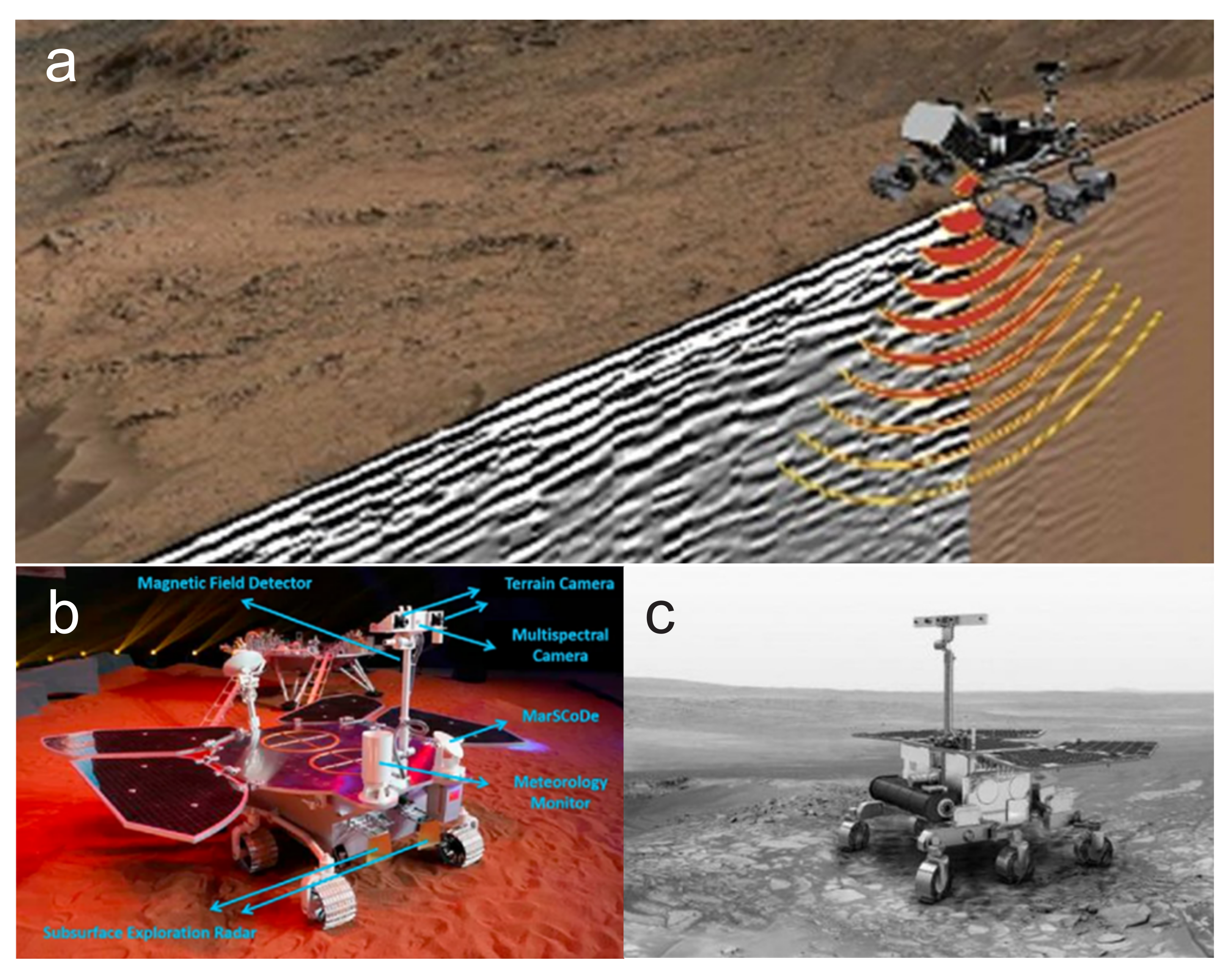
Figure 6.
Images of the rovers, including Perseverance, Zhurong, and ExoMars. (a) Scene of Perseverance driving on the surface of Mars, including the transmission of radar waves towards the subsurface by RIMFAX and the visualization of underground topography and stratigraphic structures [12]. (b) Model of the Zhurong [82]. (c) Image of the ExoMars [83].
RoPeR is a GPR launched along with the Tianwen–1 spacecraft in the same year as the Perseverance rover. Similarly to WISDOM, which will be carried by the ExoMars rover in the future, RoPeR collects data using complete polarization to explore the subsurface structure of Mars and detect the presence of water and ice beneath the Martian surface [74,84]. The complete polarization radar employs four antennas, and the polarization rotation properties of the subsurface can be measured by analyzing the data relationships between antenna combinations [85]. Full–polarization radar has been used on Earth to identify subsurface anomalies, such as cracks and pipelines [86,87]. By utilizing the polarization properties of RoPeR and future WISDOM, it is hoped that features such as lava tubes or cavities beneath the surface of Mars will be detected from multiple perspectives.
RoPeR and WISDOM utilize a polarization–sampling mode to detect subsurface water ice [84]. Under specific conditions, water ice can generate a coherent backscattering effect [88], which results in abnormally high–intensity radar signals and a high circular polarization ratio (CPR) [89]. Besides detecting water ice, studies have also found that geological targets, such as lava flows, rock surfaces, and lunar impact crater deposits can produce a high CPR, which deserves further exploration. Therefore, RoPeR and WISDOM could potentially use CPR to further investigate lava tubes.
4. Ground Penetrating Radar for Exploring Lava Tubes
In the previous sections, we introduced the existing GPR on the Moon and Mars and their working principles. In this chapter, we will focus on the characteristics of lava tubes and explore how radar data can be used to identify lava tubes.
4.1. Physical Properties of Lava Tubes
4.1.1. Morphological Properties of Lava Tubes
As shown in Figure 7a, lava tubes extend horizontally and have a cross–section that is generally arched, circular, elliptical, keyhole–shaped, or an irregular polygon, as shown in Figure 7c–f [8]. The top, sidewalls, and bottom of a lava tube are typically composed of solidified basalt. Since most lava tube walls have thin tops, the top layer of the tube near the surface sometimes collapses, especially when a channel is roofed over. The collapsed structure of the lava tube forms a skylight, which the satellite’s camera can directly observe. A chain of skylights is helpful for researchers to directly infer the size of the lava tube. In rare cases, the route of the lava tube can be determined on a map based on the arrangement of individual skylights and collapsed chains.
Basaltic volcanism is widespread on the lunar nearside [90]. Unlike Earth, volcanic activity on the Moon ceased two billion years ago [91,92], and no atmosphere exists. It can be inferred that the interior of lunar lava tubes is a vacuum. For Mars, based on the eruption record, Platz and Michael [93] inferred that Mars is still in an active state of volcanism. Throughout the entirety of human documentation, no active eruptions were found to feed active lava tubes at any location on Mars. The utilization of impressive infrared mapping techniques, such as the Thermal Emission Spectrometer and the Thermal Emission Imaging System, would be capable of exposing any ongoing eruption [94,95]. Furthermore, the release of volcanic gases during an eruption would be clearly distinguishable by the Trace Gas Orbiter instruments [96].
Regarding the scale of lava tubes, the longest mapped lava tube on Earth is Kazamura Cave in Hawaii, which is 41.8 km long [97]. In contrast, lava tubes on the Moon and Mars could be several hundreds of kilometers long, and their volume is larger, approximately 1–3 orders of magnitude larger than the Earth’s [8]. Figure 7b shows the large pits that may be the skylights of lava tubes captured by MRO.

4.1.2. Dielectric Properties of Lava Tubes
The dielectric properties of a lava tube with its surrounding environment are crucial in the radar detection of lava tubes. Electromagnetic waves emitted by GPR can penetrate the ground and propagate underground. Those among these waves that reach the lava tube’s location are reflected at the interface and are detected by the radar antenna, which measures the amplitude and propagation time of the energy reflected by underground anomalies. These anomalies are determined by contrasting the dielectric properties of the lava tube with that of the background medium and comprise the permittivity and loss tangent, which are crucial in differentiating the lava tube from the surrounding environment.
Dielectric permittivity, also known as dielectric constant, is an indicator that measures the degree to which a medium polarizes an electric field as electromagnetic waves propagate through it. The dielectric constant can be a real number (independent of frequency) or a complex number (frequency–dependent). The real part of the dielectric constant indicates the degree of polarization of the medium, and the higher the value of the real part, the stronger the response of the medium to the electric field. The imaginary part of the dielectric constant is related to the losses in the medium, indicating its ability to absorb the electric field, and is related to the medium’s energy absorption rate [99].
According to Martinez and Byrnes [100], in the GPR field, the dielectric constant is crucial in determining the speed at which electromagnetic waves penetrate through a substance, as well as the reflection coefficient at different material interfaces. The propagation speed determines how deep the radar signal can penetrate and how long it takes to return, while the reflection coefficient determines how much signal is reflected to the receiver and how much is transmitted through the interface. With this information, the dielectric constant of the subsurface materials can be estimated. Measurements of the dielectric constant of Apollo regolith samples indicate that the dielectric constant depends on the density (or equivalent porosity) and composition of the subsurface materials and is more significant in the absence of moisture [6,101,102]. Lava tubes typically have walls made of solidified basaltic lava, which generally has a higher density and dielectric constant than ordinary soil and rock.
The loss tangent describes electromagnetic waves’ energy loss as they pass through a material. It is defined as the ratio of the loss response of the electric field E to the lossless response in the curl equation:
Here, is the angular frequency of the wave, and are the real and imaginary parts of the dielectric constant of the corresponding material, respectively, and is the material’s conductivity.
Losses in GPR propagation mainly include geometric losses, attenuation losses, and scattering losses [42]. Geometric losses result from the increase in radial distance between the radar target and the sensor; attenuation losses result from the dielectric properties of the terrain; and scattering losses result from inhomogeneous media. Scattering losses can be used to compare whether there is a difference in the loss tangent between potential lava tube and non–lava tube areas to determine the possibility of potential lava tubes. When the loss tangent in potential lava tube areas is lower than in surrounding non–lava tube areas, the geometry loss of electromagnetic waves in air or vacuum can be ignored. However, when electromagnetic waves propagate in a medium, the frequency of the echo signal will broaden, resulting in a frequency shift. The slope of the frequency shift is theoretically related to the tangent value of the attenuation loss angle of electromagnetic waves in the medium [103]. The common loss tangent value estimation methods include frequency shift and amplitude attenuation [104]. In near–field detection mode, the amplitude of the reflected signal of the lunar radar is easily affected by scattering, geometric propagation, and coupling between the transmitting and receiving antennas, so the frequency shift method is relatively reliable.
During the radar observation of the lava tubes, we can analyze the dielectric properties of the lava tubes based on the radar echo signals. For example, we can estimate the dielectric constant and loss tangent of the surrounding material to determine whether it is dense rock. Then, we can estimate the loss tangent and dielectric constant of the cavity area inside the lava tube. Generally, the interior of the cavity is a vacuum, so when the estimated values are close to those of the vacuum, it can be used as one of the criteria for judgment.
4.2. Radar Echo Features of Lava Tubes
There are several geometries an orbiting radar sounders radar can scan over a lava tube [105]:
- Perpendicular (the radar motion trajectory is perpendicular to the axis of the lava tube);
- Center–parallel (the radar moves along the axis of the lava tube);
- Off–center parallel (the radar deviates from the axis of the lava tube but remains parallel to it);
- Diagonal (the radar moves at a certain angle to the axis of the lava tube). These scanning methods are shown in Figure 8.
A lava tube’s top and bottom air/rock interfaces can produce strong radar pulse reflections [105]. Additionally, the reflections at the top and bottom of the tube show opposite polarities. The polarity change is because soil/rock has a higher dielectric constant than air [105]. The top of the lava tube goes from a high dielectric constant to a low dielectric constant, producing the same polarity as the transmitted echo. On the other hand, the bottom goes from a low dielectric constant to a high dielectric constant, producing the opposite polarity to the transmitted echo. Therefore, the radar echo from a lava tube manifests as two vertically oriented hyperbolas, one originating from the top of the tube and one originating from the bottom, each composed of a bright hyperbola superimposed on some more chaotic and darker echoes. Furthermore, a clear phase reversal appears on the top hyperbola, allowing for the identification and characterization of the tube through radar data [18].
Carrer et al. [42] conducted a simulation comparing four different radar scanning geometries for lava tubes, resulting in four different radar images. Comparing the parallel scanning geometry (Figure 9c) with the diagonal scanning method (Figure 9d) reveals that the brightness of the two vertically aligned hyperbolas is similar. The top one corresponds to the apex of the lava tube, while the bottom hyperbola corresponds to the tube base, which are salient features of the lava tube [106]. The radar’s center frequency and bandwidth largely determine these features’ fidelity. The main difference between the two methods is that the diagonal scanning method is more stretched in space, with the degree of stretching related to the angle between the direction of the radar motion and the lava tube’s axis.
Regardless of the crossing direction, we can observe in each radar image that the upper and lower echoes of the lava tube exhibit a 180° phase shift due to the propagation characteristics of the electromagnetic waves. When an electromagnetic wave enters a high dielectric constant zone from a low dielectric constant zone (Figure 10a), the polarization direction of the electromagnetic wave will be flipped at the interface (Figure 10b). However, when an electromagnetic wave enters a low dielectric constant zone from a high dielectric constant zone (Figure 10c), the polarization direction of the echo signal does not flip (Figure 10d). In practical situations, when the radar transmitter emits a positive pulse, the polarization direction of the ground–reflected echo signal should be negative.
The polarization direction will be deflected as the vacuum has a low dielectric constant while the planet’s surface has a relatively high dielectric constant. As the electromagnetic pulse propagates in the medium and reaches the cavity’s upper interface, the echo signal’s polarization direction remains consistent with the emission wave. When the signal propagates to the cavity’s bottom interface, the echo signal’s polarization is deflected, in opposition to the emission wave’s. In theory, phase reversal can be used as an effective criterion for lava tube identification. However, in practice, the interference patterns among multiple echoes caused by cracks and irregular tube tops in the lava tube’s covering layer are complicated, making it difficult to determine the polarization of the reflection from the cavity space. In this case, the key to locating the lava tube is to identify high–amplitude reflections from the top of the tube and separate them from other reflection areas in the radar image, such as hard rocks, which can be used as one of the criteria for judging the lava tube [18,105].
Esmaeili et al. [18] constructed three synthetic models for the Valentine Cave on Earth based on the different dielectric properties of Earth, the Moon, and Mars (Figure 11). The research results suggest that the GPR technology used to detect lava tubes on Earth can be extended to the Moon and Mars.
4.3. Mechanisms of Radar Detection of Lava Tubes
The radar echo features of lava tubes can be summarized as follows:
- Two vertically aligned hyperbolic curves are formed, with a bright hyperbolic curve hanging over some more disordered and darker echoes.
- The phase difference between the radar echoes of the two curves is 180°.
These are characteristics that can distinguish the echoes of lava tubes from noise. By combining the difference in dielectric properties between lava tubes and underground structures, radar can effectively locate lava tubes.
During actual radar detection, craters and volcanic vents are the main surface features that cause underground interference. The lunar surface contains a multitude of craters of varying sizes, which can create features with two vertically aligned hyperbolic curves, easily mistaken for lava tubes [42]. Since volcanic vents and lava tubes have drastically different shapes, it is not easy to differentiate between them based on power characteristics. However, the phase information of the signal provides a vital differentiation criterion. While the hyperbolic curves of craters and volcanic vents exhibit the same phase, the hyperbolic curves of lava tubes show an apparent phase reversal in their upper part, providing a means of distinguishing between noise and lava tube echoes.
Therefore, the radar detection process for identifying lava tubes can be summarized as follows (Figure 12):
- Collect radar data and subject them to preprocessing;
- Denoise the data and extract the apparent hyperbolic curve echoes from the potential cavity areas;
- Extract the polarity of the echo signal at the cavity’s upper edge and compare it with the polarity of the incident wave to make a preliminary judgment;
- Estimate the dielectric properties (dielectric constant and loss tangent) of the cavity and surrounding non–cavity areas and compare their differences;
- Make a final judgment and output the result.
4.4. TubeX Project
NASA sponsored the TubeX program to explore lava tubes beneath the surface of celestial bodies using geophysical methods, particularly GPR, seismic, and electromagnetic techniques, to plan potential base locations on extraterrestrial surfaces [18,29]. The GPR technology was applied in the field detection of lava tubes in the lava bed National Park in California, USA (Figure 13), and the imaging of the Skull lava tube using GPR was carried out (Figure 13e) [107]. The lava tube exhibits hyperbolic curve features in the radar image, with the upper and lower curves characterizing the vertical depth of the lava tube, which is about 18 m, consistent with the measured values, verifying the feasibility of using GPR to detect lava tubes [108,109]. Therefore, GPR technology has the potential to detect lava tubes on celestial bodies.
5. Distribution of Lava Tubes on the Moon
Three methods can be used to detect lava tubes on celestial bodies: image detection, radar detection, and direct detection [18,110].
- Image detection involves analyzing the surface images of celestial bodies to detect possible lava tubes. This method can indirectly discover some anomalies on the surfaces of celestial bodies, such as skylights and collapsed lava tubes, but cannot directly detect the interior of lava tubes.
- Radar detection, as discussed in this paper, can detect the location of lava tubes at deeper layers compared to image detection, with the advantages of high resolution, high sensitivity, and fewer interferences from other features on extraterrestrial surfaces.
- Direct detection involves using rovers or other equipment to enter the lava tube and measure the physical quantities including temperature, gas composition, and magnetic field fluctuations to analyze the lava tube’s structure, composition, and characteristics. This method requires advanced technology and is challenging to operate, but it can reveal more detailed lava tube structures and features.
Currently, remote sensing has been widely used in lava tube–related research [8,111]. Some researchers have also applied radar detection to search for lava tubes [7,19]. However, direct detection is still in the theoretical stage due to high costs and implementation difficulties. Torrese et al. [110] pointed out that electrical resistivity tomography (ERT) is particularly suitable for identifying cavities and geological boundaries and can be used for planetary volcanic–like stratigraphic surveys. Compared with GPR, ERT can provide a greater survey depth and is less sensitive to conductive cover layers [110]. Wagner and Robinson [112] provides a comprehensive summary of lunar pits, in which they identify the challenges associated with viewing pit interiors from the Moon’s surface, and traversing these interiors. Due to the steep slopes, loose materials, and presence of large boulders, they suggest that initial pit exploration should be carried out using flying vehicles. Miaja et al. [113] designed a crane model that can deploy detection robots into the interior of a cave; Kalita et al. [114] proposed a small spherical robot platform called SphereX, with a volume of only a few liters and a mass of a few kilograms, which is capable of jumping and rolling, and which can be used for detecting lava tubes. In addition, Hooper et al. [115] proposed a new concept called “green reconnaissance”. This method aims to solve the pollution caused by the rocket exhaust and water sublimation to ensure the accuracy of scientific research. Following the principles of maximizing site protection and reducing pollution, this method uses instruments and robots to conduct scientific surveys underground.
Haruyama et al. [111] used two high–resolution cameras on the SELENE (Kaguya) probe: the terrain camera (TC) and multi–band imager (MI), and discovered a possible lava tube skylight in the Marius Hills area on the near side of the Moon, as shown in Figure 14. These two cameras can capture the images of the lunar surface under different solar illumination conditions and estimate the depth and shape of the opening by comparing the shadows and brightness in the images. The skylight the article discovered is an approximately circular hole with a diameter of about 65 m and an estimated depth of between 80 and 88 m. It is located in a curved ravine, without obvious volcanic ejecta or adjacent pits, and may be related to potential faults or vein structures. The article suggests that this hole is a skylight of a lava tube, a small hole formed by the collapse of a lava tube roof due to cooling or impact. The article also points out that this lava tube may be covered by a thin layer of lava (20–25 m), which helps to protect it from meteoroid impacts.
Kaku et al. [19] also utilized data from the SELENE Lunar Radar Sounder (LRS) to search for intact lunar lava tubes in the Marius Hills region of the Moon. The researchers conducted surveys near the area and discovered a unique echo pattern characterized by a steep drop in echo power, followed by a sizeable second peak. This echo pattern is similar to those observed from known lava tubes on Earth, leading the researchers to speculate that this could be evidence of lava tubes on the Moon. The lava tube is situated beneath a rille, referred to as the Marius Hills Hole (MHH), in the Marius Hills area of the Moon, which may have been formed due to volcanic activity. The entrance of the lava tube is a large cave called the Marius Hills Hole, with a diameter and depth of 50 m. The lava tube’s interior may be spacious, with heights exceeding 15 m and lengths possibly extending up to several dozens of kilometers. To further verify this hypothesis, the researchers extended their search area to 13.00–15.00° N or 301.85–304.01° E around MHH and observed similar LRS echo patterns at several locations, as shown in Figure 15. These results suggest the possibility of intact lunar lava tubes in the Marius Hills region.
Lava tubes are a specific type of subsurface cavity. In the CE–3 mission, Ding et al. [7] utilized a high–frequency Moon–based GPR carried by the Yutu rover to detect a potential underground cavity, as shown in Figure 16. The cavity was situated within the ejecta deposits of overlapping Ziwei craters, with surrounding materials having a relatively low dielectric constant. By simulating the propagation of electromagnetic waves in the media, the authors estimated the shape and size of the cavity. The potential cavity was estimated to be approximately 3.1 m in height, with an unknown width. Although the width was not constrained, researchers could speculate on the shape at its top. This discovery suggests that more similar natural structures may exist underground on the Moon, which could serve as essential resources for future lunar exploration missions to provide ideal shelters and protection.
6. Distribution of Lava Tubes on Mars
Zhao et al. [116] identified 38 lava tubes in the Tharsis region of southeastern Mars and analyzed their morphological and distributional characteristics using high–resolution imagery and terrain data, as shown in Figure 17. These tubes appear in the form of winding ridges on the lava plains. The lava tubes have three main cross–sectional shapes: circular, double–ridged, and flat–crested (as shown in Figure 18), and are accompanied by other features such as branching, axial fissures, collapse depressions, protruding lava flows, and lava deltas fed from the tubes. These lava tubes primarily formed during the late Hesperian period and remained active until the Hesperian–Amazonian boundary.
Mansilla et al. [117] detected underground structures from the late Amazonian lava flows in the Elysium Mons region using the SHARAD radar instrument on the MRO. Five consecutive underground reflectors and a long chain of pits were discovered. These underground reflectors are situated at the base of a lava fan, at depths of approximately 35–79 m, forming around 59 million years ago. The lava fan stands 80 m above the surrounding terrain and retains marks from past events on its surface. The long chain of pits is located above a lava flow to the north, at a depth of about 30 m, and is believed to have formed from the collapse of a lava tube. The article estimated the diameter of the lava tube to be 30 m and its length to be 1.5 km, making it one of the giant known lava tubes on Mars [117]. Currently, the potential lava tubes have been reported in the Solis Planum, Echus Chasma, Arsia, and Olympus regions on Mars [8,116,117]. Those potential lava tubes need to be further investigated by radar observation. Table 6 lists the information on potential lava tubes on Mars.
7. The Potential Utilization of Lava Tubes: Indications to the Sites for Future Bases on the Moon and Mars
Lava tubes differ from regular tunnels because they do not require artificial maintenance or support structures, displaying natural forms and stable environments. They can be a natural barrier to potential hazards such as cosmic rays and meteorite impacts. Furthermore, the interiors of lava tubes have unique environmental conditions. The temperature can gradually reach a constant temperature at a depth of approximately one meter below the lunar surface. Recent studies have shown that the constant temperature reached inside lunar lava tubes is approximately 290 K [118]. Lava tubes can potentially be widely used in transportation, infrastructure construction, scientific research, and many other fields. They may play an essential role in constructing future bases on the Moon and Mars. Due to their natural formation and relatively stable characteristics, lava tubes’ long–term stability and operating ability are relatively high, potentially making them a safe, reliable, and convenient form of usage. They also provide a mild, stable, and safe environment for the long–term scientific exploration and habitation, enabling the establishment of future human habitats in lunar underground spaces, as conceptualized in Figure 19. These may provide excellent environmental protection for the lives and work of future astronauts.
In addition, researching lava tubes also has significant scientific research value. The formation, location, age, composition, and morphology of lava tubes are closely related to the geological histories of planets. By analyzing lava tubes, we can better understand the geological characteristics of different depth areas inside the planet, infer the structure and evolutionary history of the planet’s interior, and help scientists understand the situation beneath the planet’s subsurface [46]. Moreover, studying lava tubes is also essential in exploring the possibility and characteristics of extraterrestrial life. Léveillé and Datta [27] have stated that lava tubes can provide protection against extreme weather fluctuations such as dust storms and can better avoid the effects of cosmic–ray radiation compared to the Martian surface. Consequently, there may be biological markers preserved in cave minerals, such as chemical, molecular, isotopic, and morphological markers, which can potentially become the best evidence for the past existence of life, thereby better understanding the possible forms and characteristics of extraterrestrial life.
8. Conclusions and Perspectives
This paper systematically reviews the formation mechanism of lava tubes on the Moon and Mars, as well as the principles of GPR detection, and summarizes the terrain changes and dielectric properties of lava tubes. These features can help us better analyze the radar echoes of lava tubes and determine their feasible detection mechanisms. By analyzing the current detection of lava tubes on the Moon and Mars, it is affirmed that radar has enormous potential in detecting lava tubes. In the future, there will be more radar observations, such as CE–7 and WISDOM, to explore lava tubes and underground cavities on the Moon and Mars. New radars will carry new equipment and technology to provide the radar images with higher signal–to–noise ratios, a deeper detection depth, and higher resolution to better understand the Moon’s and Mars’s geological features. However, merely locating lava tubes through radar detection is just the beginning. Additional equipment is needed for further exploration to fully utilize the resources of lava tubes on the Moon and Mars.
Although orbiting–based radar can perform the global and comprehensive detection of valuable lava tubes, its low resolution prevents the accurate detection of individual or small lava tubes. Therefore, it is necessary to use high–precision radar onboard the rover to conduct the refined scanning of confirmed targets for subsequent utilization and development. In the future, robots will also enter lava tubes for in–site exploration, which requires accurate detection maps to help plan exploration routes for robots and further understand the situation of the lava tubes (such as determining the robustness and capacity of the lava tubes for future human settlements through wall thickness and material). Once the suitability of the lava tube is confirmed, the construction of underground human exploration bases can commence, heralding a promising new era of subterranean exploration on the Moon and Mars.
Author Contributions
Conceptualization, C.D.; methodology, X.Q. and C.D.; software, X.Q. and C.D.; validation, X.Q. and C.D.; formal analysis, X.Q. and C.D.; investigation, X.Q. and C.D. resources, C.D.; data curation, X.Q. and C.D.; writing—original draft preparation, X.Q. and C.D.; writing—review and editing, C.D.; visualization, C.D.; project administration, C.D.; supervision, C.D. funding acquisition, C.D. All authors have read and agreed to the published version of the manuscript.
Funding
This work is supported by the National Natural Science Foundation of China (Grant No. 42241139 and 42004099), the Opening Fund of the Key Laboratory of Lunar and Deep Space Exploration, Chinese Academy of Sciences (No. LDSE202005), the Fund of Shanghai Institute of Aerospace System Engineering (No. PZ_YY_SYF_JY200275), and the Shenzhen Municipal Government Investment Project (No. 2106_440300_04_03_901272).
Conflicts of Interest
The authors declare no conflict of interest.
Correction Statement
This article has been republished with a minor correction to the existing affiliation information.
"Institute of Advance Study" should change to "Institute for Advanced Study". This change does not affect the scientific content of the article.
References
- Ding, C.; Feng, J.; Zheng, L.; Dai, S.; Xing, S.; Xiao, Y.; Su, Y. A Review of Applications of Radar-Detection Techniques in Lunar Explorations. Astron. Res. Technol. 2015, 12, 228–242. [Google Scholar] [CrossRef]
- Zheng, Y.C. Mars exploration in 2020. Innovation 2020, 1, 100036. [Google Scholar] [CrossRef]
- Crawford, I.; Anand, M.; Cockell, C.; Falcke, H.; Green, D.; Jaumann, R.; Wieczorek, M. Back to the Moon: The scientific rationale for resuming lunar surface exploration. Planet. Space Sci. 2012, 74, 3–14. [Google Scholar] [CrossRef] [Green Version]
- Burns, J.A. The four hundred years of planetary science since Galileo and Kepler. Nature 2010, 466, 575–584. [Google Scholar] [CrossRef] [PubMed]
- Carr, M.H. The Surface of Mars; Cambridge University Press: Cambridge, UK, 2007; Volume 6. [Google Scholar]
- Carrier, W.D., III; Olhoeft, G.R.; Mendell, W. Physical Properties of the Lunar surface. Lunar Sourcebook, a User’s Guide to the Moon; Cambridge University Press: Cambridge, UK, 1991; pp. 475–594. [Google Scholar]
- Ding, C.; Xiao, Z.; Su, Y. A potential subsurface cavity in the continuous ejecta deposits of the Ziwei crater discovered by the Chang’E-3 mission. Earth Planets Space 2021, 73, 53. [Google Scholar] [CrossRef]
- Sauro, F.; Pozzobon, R.; Massironi, M.; De Berardinis, P.; Santagata, T.; De Waele, J. Lava tubes on Earth, Moon and Mars: A review on their size and morphology revealed by comparative planetology. Earth-Sci. Rev. 2020, 209, 103288. [Google Scholar] [CrossRef]
- Blair, D.M.; Chappaz, L.; Sood, R.; Milbury, C.; Bobet, A.; Melosh, H.J.; Howell, K.C.; Freed, A.M. The structural stability of lunar lava tubes. Icarus 2017, 282, 47–55. [Google Scholar] [CrossRef]
- Elachi, C.; Cimino, J.; Settle, M. Overview of the Shuttle Imaging Radar-B preliminary scientific results. Science 1986, 232, 1511–1516. [Google Scholar] [CrossRef] [PubMed]
- Fang, G.Y.; Zhou, B.; Ji, Y.C.; Zhang, Q.Y. Lunar Penetrating Radar onboard the Chang’e-3 mission. Res. Astron. Astrophys. 2014, 14, 1607. [Google Scholar] [CrossRef]
- Hamran, S.E.; Paige, D.A.; Amundsen, H.E.F.; Berger, T.; Brovoll, S.; Carter, L.; Damsgård, L.; Dypvik, H.; Eide, J.; Eide, S.; et al. Radar Imager for Mars’ Subsurface Experiment—RIMFAX. Space Sci. Rev. 2020, 216, 128. [Google Scholar] [CrossRef]
- Li, C.; Wang, C.; Wei, Y.; Lin, Y. China’s present and future lunar exploration program. Science 2019, 365, 238–239. [Google Scholar] [CrossRef]
- Ono, T.; Kumamoto, A.; Nakagawa, H.; Yamaguchi, Y.; Oshigami, S.; Yamaji, A.; Kobayashi, T.; Kasahara, Y.; Oya, H. Lunar Radar Sounder Observations of Subsurface Layers Under the Nearside Maria of the Moon. Science 2009, 323, 909–912. [Google Scholar] [CrossRef] [PubMed] [Green Version]
- Seu, R.; Phillips, R.J.; Biccari, D.; Orosei, R.; Masdea, A.; Picardi, G.; Safaeinili, A.; Campbell, B.A.; Plaut, J.J.; Marinangeli, L.; et al. SHARAD sounding radar on the Mars Reconnaissance Orbiter. J. Geophys. Res. Planets 2007, 112, E5. [Google Scholar] [CrossRef]
- Zhou, B.; Shen, S.; Lu, W.; Liu, Q.; Tang, C.; Li, S.; Fang, G. The Mars rover subsurface penetrating radar onboard China’s Mars 2020 mission. Earth Planet. Phys. 2020, 4, 345–354. [Google Scholar] [CrossRef]
- Jol, H.M. Ground Penetrating Radar Theory and Applications; Elsevier: Amsterdam, The Netherlands, 2008. [Google Scholar]
- Esmaeili, S.; Kruse, S.; Jazayeri, S.; Whelley, P.; Bell, E.; Richardson, J.; Garry, W.B.; Young, K. Resolution of Lava Tubes With Ground Penetrating Radar: The TubeX Project. J. Geophys. Res. Planets 2020, 125, e2019JE006138. [Google Scholar] [CrossRef]
- Kaku, T.; Haruyama, J.; Miyake, W.; Kumamoto, A.; Ishiyama, K.; Nishibori, T.; Yamamoto, K.; Crites, S.T.; Michikami, T.; Yokota, Y.; et al. Detection of Intact Lava Tubes at Marius Hills on the Moon by SELENE (Kaguya) Lunar Radar Sounder. Geophys. Res. Lett. 2017, 44, 10155–10161. [Google Scholar] [CrossRef]
- Brož, P.; Bernhardt, H.; Conway, S.J.; Parekh, R. An overview of explosive volcanism on Mars. J. Volcanol. Geotherm. Res. 2021, 409, 107125. [Google Scholar] [CrossRef]
- Ivanov, B.A. Mars/Moon Cratering Rate Ratio Estimates. Space Sci. Rev. 2001, 96, 87–104. [Google Scholar] [CrossRef]
- Spudis, P.D. Chapter 39—Volcanism on the Moon. In The Encyclopedia of Volcanoes, 2nd ed.; Sigurdsson, H., Ed.; Academic Press: Amsterdam, The Netherlands, 2015; pp. 689–700. [Google Scholar] [CrossRef]
- Valerio, A.; Tallarico, A.; Dragoni, M. Mechanisms of formation of lava tubes. J. Geophys. Res. Solid Earth 2008, 113. [Google Scholar] [CrossRef]
- Haruyama, J.; Morota, T.; Kobayashi, S.; Sawai, S.; Lucey, P.G.; Shirao, M.; Nishino, M.N. Lunar holes and lava tubes as resources for lunar science and exploration. In Moon: Prospective Energy and Material Resources; Springer: Berlin/Heidelberg, Germany, 2012; pp. 139–163. [Google Scholar]
- Horz, F. Lava tubes-potential shelters for habitats. In Lunar Bases and Space Activities of the 21st Century; Lunar and Planetary Institute: Houston, TX, USA, 1985; pp. 405–412. [Google Scholar]
- Benaroya, H. Turning Dust to Gold: Building a Future on the Moon and Mars; Springer Science & Business Media: Berlin/Heidelberg, Germany, 2016. [Google Scholar]
- Léveillé, R.J.; Datta, S. Lava tubes and basaltic caves as astrobiological targets on Earth and Mars: A review. Planet. Space Sci. 2010, 58, 592–598. [Google Scholar] [CrossRef]
- Kauahikaua, J.; Cashman, K.V.; Mattox, T.N.; Heliker, C.C.; Hon, K.A.; Mangan, M.T.; Thornber, C.R. Observations on basaltic lava streams in tubes from Kilauea Volcano, island of Hawai’i. J. Geophys. Res. Solid Earth 1998, 103, 27303–27323. [Google Scholar] [CrossRef]
- Bell, E.; Schmerr, N.; Young, K.; Esmaeili, S.; Garry, W.B.; Jazayeri, S.; Kruse, S.; Richardson, J.; Whelley, P. Field Mapping and Modeling of Terrestrial Lava Tube Magnetic Anomalies as an Analog for Lunar Lava Tube Exploration and Prospecting. J. Geophys. Res. Planets 2022, 127, e2021JE007140. [Google Scholar] [CrossRef]
- Sharygin, V.V.; Kamenetsky, V.S.; Zhitova, L.M.; Belousov, A.B.; Abersteiner, A. Copper-Containing Magnesioferrite in Vesicular Trachyandesite in a Lava Tube from the 2012–2013 Eruption of the Tolbachik Volcano, Kamchatka, Russia. Minerals 2018, 8, 514. [Google Scholar] [CrossRef] [Green Version]
- Crown, D.A.; Scheidt, S.P.; Berman, D.C. Distribution and Morphology of Lava Tube Systems on the Western Flank of Alba Mons, Mars. J. Geophys. Res. Planets 2022, 127, e2022JE007263. [Google Scholar] [CrossRef]
- Duraiswami, R.A.; Bondre, N.R.; Managave, S. Morphology of rubbly pahoehoe (simple) flows from the Deccan Volcanic Province: Implications for style of emplacement. J. Volcanol. Geotherm. Res. 2008, 177, 822–836. [Google Scholar] [CrossRef]
- Hon, K.; Kauahikaua, J.; Denlinger, R.; Mackay, K. Emplacement and inflation of pahoehoe sheet flows: Observations and measurements of active lava flows on Kilauea Volcano, Hawaii. Geol. Soc. Am. Bull. 1994, 106, 351–370. [Google Scholar] [CrossRef]
- Peterson, D.W.; Holcomb, R.T.; Tilling, R.I.; Christiansen, R.L. Development of lava tubes in the light of observations at Mauna Ulu, Kilauea Volcano, Hawaii. Bull. Volcanol. 1994, 56, 343–360. [Google Scholar] [CrossRef]
- Theinat, A.K.; Modiriasari, A.; Bobet, A.; Melosh, H.J.; Dyke, S.J.; Ramirez, J.; Maghareh, A.; Gomez, D. Lunar lava tubes: Morphology to structural stability. Icarus 2020, 338, 113442. [Google Scholar] [CrossRef]
- Daniels, D.J. Ground Penetrating Radar; IET: Stevenage, UK, 2004; Volume 1. [Google Scholar]
- Zeng, Z.; Liu, S.; Xuan, F. Principle and Application of Ground Penetrating Radar; Beijing Electronics Industry Press: Beijing, China, 2010. [Google Scholar]
- Porcello, L.J.; Jordan, R.L.; Zelenka, J.S.; Adams, G.F.; Phillips, R.J.; Brown, W.E.; Ward, S.H.; Jackson, P.L. The Apollo lunar sounder radar system. Proc. IEEE 1974, 62, 769–783. [Google Scholar] [CrossRef]
- Platz, T.; Byrne, P.K.; Massironi, M.; Hiesinger, H. Volcanism and tectonism across the inner solar system: An overview. Geol. Soc. London, Spec. Publ. 2015, 401, 1–56. [Google Scholar] [CrossRef]
- Ono, T.; Oya, H. Lunar Radar Sounder (LRS) experiment on-board the SELENE spacecraft. Earth Planets Space 2000, 52, 629–637. [Google Scholar] [CrossRef] [Green Version]
- Ohtake, M.; Haruyama, J.; Matsunaga, T.; Yokota, Y.; Morota, T.; Honda, C.; LISM Team. Performance and scientific objectives of the SELENE (KAGUYA) Multiband Imager. Earth Planets Space 2008, 60, 257–264. [Google Scholar] [CrossRef] [Green Version]
- Carrer, L.; Gerekos, C.; Bruzzone, L. A multi-frequency radar sounder for lava tubes detection on the Moon: Design, performance assessment and simulations. Planet. Space Sci. 2018, 152, 1–17. [Google Scholar] [CrossRef]
- Wang, R.; Yan, S. A Review of Application of Surface Penetrating Radar in the Moon and Deep-space Exploration. Astron. Res. Technol. 2020, 17, 492–512. [Google Scholar]
- Ono, T.; Kumamoto, A.; Kasahara, Y.; Yamaguchi, Y.; Yamaji, A.; Kobayashi, T.; Oshigami, S.; Nakagawa, H.; Goto, Y.; Hashimoto, K.; et al. The Lunar Radar Sounder (LRS) Onboard the KAGUYA (SELENE) Spacecraft. Space Sci. Rev. 2010, 154, 145–192. [Google Scholar] [CrossRef]
- Zuber, M.T.; Smith, D.E.; Watkins, M.M.; Asmar, S.W.; Konopliv, A.S.; Lemoine, F.G.; Melosh, H.J.; Neumann, G.A.; Phillips, R.J.; Solomon, S.C. Gravity field of the Moon from the Gravity Recovery and Interior Laboratory (GRAIL) mission. Science 2013, 339, 668–671. [Google Scholar] [CrossRef] [Green Version]
- Crawford, I.A.; Joy, K.H. Lunar exploration: Opening a window into the history and evolution of the inner Solar System. Philos. Trans. R. Soc. A Math. Phys. Eng. Sci. 2014, 372, 20130315. [Google Scholar] [CrossRef] [Green Version]
- Kobayashi, T.; Kim, J.H.; Lee, S.R. HF (5 MHz) imaging of the moon by Kaguya lunar radar sounder off nadir echo data. IEEE Trans. Geosci. Remote Sens. 2018, 56, 3709–3714. [Google Scholar] [CrossRef]
- Sood, R.; Melosh, H.J.; Howell, K.C. Lunar Advanced Radar Orbiter for Subsurface Sounding (Laross): Lava Tube Exploration Mission. In Proceedings of the 26th AAS/AIAA Space Flight Mechanics Meeting, Napa, CA, USA, 14–18 February 2016; Volume 158, pp. 3823–3837. [Google Scholar]
- Jordan, R.; Picardi, G.; Plaut, J.; Wheeler, K.; Kirchner, D.; Safaeinili, A.; Johnson, W.; Seu, R.; Calabrese, D.; Zampolini, E. The Mars express MARSIS sounder instrument. Planet. Space Sci. 2009, 57, 1975–1986. [Google Scholar] [CrossRef]
- Li, C.; Zhang, R.; Yu, D.; Dong, G.; Liu, J.; Geng, Y.; Sun, Z.; Yan, W.; Ren, X.; Su, Y.; et al. China’s Mars Exploration Mission and Science Investigation. Space Sci. Rev. 2021, 217, 57. [Google Scholar] [CrossRef]
- Fan, M.; Lyu, P.; Su, Y.; Du, K.; Zhang, Q.; Zhang, Z.; Dai, S.; Hong, T. The Mars Orbiter Subsurface Investigation Radar (MOSIR) on China’s Tianwen-1 Mission. Space Sci. Rev. 2021, 217, 8. [Google Scholar] [CrossRef]
- XIONG, S. Orbiter-based subsurface sounding radar for searching water ice on Mars. ACTA Geol. Sin. 2021, 95, 2823–2842. [Google Scholar] [CrossRef]
- Seu, R.; Biccari, D.; Orosei, R.; Lorenzoni, L.; Phillips, R.; Marinangeli, L.; Picardi, G.; Masdea, A.; Zampolini, E. SHARAD: The MRO 2005 shallow radar. Planet. Space Sci. 2004, 52, 157–166. [Google Scholar] [CrossRef]
- Orosei, R.; Ding, C.; Fa, W.; Giannopoulos, A.; Hérique, A.; Kofman, W.; Lauro, S.E.; Li, C.; Pettinelli, E.; Su, Y.; et al. The global search for liquid water on Mars from orbit: Current and future perspectives. Life 2020, 10, 120. [Google Scholar] [CrossRef]
- Hong, T.; Su, Y.; Fan, M.; Dai, S.; Lv, P.; Ding, C.; Zhang, Z.; Wang, R.; Liu, C.; Du, W.; et al. Flight Experiment Validation of Altitude Measurement Performance of MOSIR on Tianwen-1 Orbiter. Remote Sens. 2021, 13, 5049. [Google Scholar] [CrossRef]
- Hong, T.; Su, Y.; Dai, S.; Zhang, Z.; Du, W.; Liu, C.; Liu, S.; Wang, R.; Ding, C.; Li, C. An Improved Method of Surface Clutter Simulation Based on Orbiting Radar in Tianwen-1 Mars Exploration. Radio Sci. 2022, 57, e2022RS007491. [Google Scholar] [CrossRef]
- Ding, C.; Li, Q.; Xu, J.; Lei, Z.; Li, J.; Su, Y.; Huang, S. Moon-Based Ground Penetrating Radar Derivation of the Helium-3 Reservoir in the Regolith at the Chang’E-3 Landing Site. IEEE J. Sel. Top. Appl. Earth Obs. Remote Sens. 2023, 16, 2764–2776. [Google Scholar] [CrossRef]
- Li, C.; Xing, S.; Lauro, S.E.; Su, Y.; Dai, S.; Feng, J.; Cosciotti, B.; Di Paolo, F.; Mattei, E.; Xiao, Y.; et al. Pitfalls in GPR data interpretation: False reflectors detected in Lunar radar cross sections by Chang’e-3. IEEE Trans. Geosci. Remote Sens. 2017, 56, 1325–1335. [Google Scholar] [CrossRef]
- Honglei, L.; Chunyu, D.; Xuesen, X.; Jinhai, Z.; Yong, W.; Yangting, L. Review on the in situ spectroscopy and radar remote sensing on the Moon. Rev. Geophys. Planet. Phys. 2021, 52, 373–390. [Google Scholar]
- Ding, C.; Su, Y.; Xing, S.; Dai, S.; Xiao, Y.; Feng, J.; Liu, D.; Li, C. Numerical simulations of the lunar penetrating radar and investigations of the geological structures of the lunar regolith layer at the Chang’E 3 landing site. Int. J. Antennas Propag. 2017, 2017, 3013249. [Google Scholar] [CrossRef] [Green Version]
- Wang, R.; Su, Y.; Ding, C.; Dai, S.; Liu, C.; Zhang, Z.; Hong, T.; Zhang, Q.; Li, C. A novel approach for permittivity estimation of lunar regolith using the lunar penetrating radar onboard Chang’E-4 rover. Remote Sens. 2021, 13, 3679. [Google Scholar] [CrossRef]
- Dai, S.; Su, Y.; Xiao, Y.; Feng, J.Q.; Xing, S.G.; Ding, C.Y. Echo simulation of lunar penetrating radar: Based on a model of inhomogeneous multilayer lunar regolith structure. Res. Astron. Astrophys. 2014, 14, 1642. [Google Scholar] [CrossRef]
- Ding, C.; Xiao, Z.; Wu, B.; Li, Y.; Prieur, N.C.; Cai, Y.; Su, Y.; Cui, J. Fragments Delivered by Secondary Craters at the Chang’E-4 Landing Site. Geophys. Res. Lett. 2020, 47, e2020GL087361. [Google Scholar] [CrossRef]
- Xiao, Y.; Su, Y.; Dai, S.; Feng, J.; Xing, S.; Ding, C.; Li, C. Ground experiments of Chang’e-5 lunar regolith penetrating radar. Adv. Space Res. 2019, 63, 3404–3419. [Google Scholar] [CrossRef]
- Su, Y.; Wang, R.; Deng, X.; Zhang, Z.; Zhou, J.; Xiao, Z.; Ding, C.; Li, Y.; Dai, S.; Ren, X.; et al. Hyperfine structure of regolith unveiled by Chang’E-5 lunar regolith penetrating radar. IEEE Trans. Geosci. Remote Sens. 2022, 60, 1–14. [Google Scholar] [CrossRef]
- Li, C.; Liu, J.; Ren, X.; Zuo, W.; Tan, X.; Wen, W.; Li, H.; Mu, L.; Su, Y.; Zhang, H.; et al. The Chang’e 3 Mission Overview. Space Sci. Rev. 2015, 190, 85–101. [Google Scholar] [CrossRef]
- Li, C.; Zuo, W.; Wen, W.; Zeng, X.; Gao, X.; Liu, Y.; Fu, Q.; Zhang, Z.; Su, Y.; Ren, X.; et al. Overview of the Chang’e-4 Mission: Opening the Frontier of Scientific Exploration of the Lunar Far Side. Space Sci. Rev. 2021, 217, 35. [Google Scholar] [CrossRef]
- Wang, J.; Zhang, Y.; Di, K.; Chen, M.; Duan, J.; Kong, J.; Xie, J.; Liu, Z.; Wan, W.; Rong, Z.; et al. Localization of the Chang’e-5 Lander Using Radio-Tracking and Image-Based Methods. Remote Sens. 2021, 13, 590. [Google Scholar] [CrossRef]
- CLEP. A Notice on the Selection of the Payload Competition for the Fourth Phase of the Chang’e-7 Mission in the Lunar Exploration Project; China’s Lunar and Deep Space Exploration: Beijing, China, 2020; Available online: http://www.clep.org.cn/n6020511/c6810049/content.html (accessed on 1 May 2023).
- Feng, J.; Siegler, M.A.; White, M.N. Shallow Regolith Structure and Obstructions Detected by Lunar Regolith Penetrating Radar at Chang’E-5 Drilling Site. Remote Sens. 2022, 14, 3378. [Google Scholar] [CrossRef]
- Jia, Y.; Zou, Y.; Ping, J.; Xue, C.; Yan, J.; Ning, Y. The scientific objectives and payloads of Chang’e-4 mission. Planet. Space Sci. 2018, 162, 207–215. [Google Scholar] [CrossRef]
- Li, Y.; Lu, W.; Fang, G.; Zhou, B.; Shen, S. Performance verification of Lunar Regolith Penetrating Array Radar of Chang’E-5 mission. Adv. Space Res. 2019, 63, 2267–2278. [Google Scholar] [CrossRef]
- Xing, S.G.; Su, Y.; Feng, J.Q.; Dai, S.; Xiao, Y.; Ding, C.Y.; Li, C.L. The penetrating depth analysis of Lunar Penetrating Radar onboard Chang’e-3 rover. Res. Astron. Astrophys. 2017, 17, 046. [Google Scholar] [CrossRef]
- Zou, Y.; Zhu, Y.; Bai, Y.; Wang, L.; Jia, Y.; Shen, W.; Fan, Y.; Liu, Y.; Wang, C.; Zhang, A.; et al. Scientific objectives and payloads of Tianwen-1, China’s first Mars exploration mission. Adv. Space Res. 2021, 67, 812–823. [Google Scholar] [CrossRef]
- Huang, H.; Liu, J.; Wang, X.; Chen, Y.; Zhang, Q.; Liu, D.; Yan, W.; Ren, X. The Analysis of Cones within the Tianwen-1 Landing Area. Remote Sens. 2022, 14, 2590. [Google Scholar] [CrossRef]
- Bruno, B.C.; Fagents, S.; Hamilton, C.; Burr, D.; Baloga, S. Identification of volcanic rootless cones, ice mounds, and impact craters on Earth and Mars: Using spatial distribution as a remote sensing tool. J. Geophys. Res. Planets 2006, 111, E6. [Google Scholar] [CrossRef]
- Xiao, L.; Wang, C. Geologic features of Wudalianchi volcanic field, northeastern China: Implications for Martian volcanology. Planet. Space Sci. 2009, 57, 685–698. [Google Scholar] [CrossRef]
- Wu, B.; Dong, J.; Wang, Y.; Rao, W.; Sun, Z.; Li, Z.; Tan, Z.; Chen, Z.; Wang, C.; Liu, W.C.; et al. Landing Site Selection and Characterization of Tianwen-1 (Zhurong Rover) on Mars. J. Geophys. Res. Planets 2022, 127, e2021JE007137. [Google Scholar] [CrossRef]
- Quantin-Nataf, C.; Carter, J.; Mandon, L.; Thollot, P.; Balme, M.; Volat, M.; Pan, L.; Loizeau, D.; Millot, C.; Breton, S.; et al. Oxia Planum: The landing site for the ExoMars “Rosalind Franklin” rover mission: Geological context and prelanding interpretation. Astrobiology 2021, 21, 345–366. [Google Scholar] [CrossRef]
- Ciarletti, V.; Clifford, S.; Plettemeier, D.; Le Gall, A.; Hervé, Y.; Dorizon, S.; Quantin-Nataf, C.; Benedix, W.S.; Schwenzer, S.; Pettinelli, E.; et al. The WISDOM Radar: Unveiling the Subsurface Beneath the ExoMars Rover and Identifying the Best Locations for Drilling. Astrobiology 2017, 17, 565–584. [Google Scholar] [CrossRef]
- Sugak, V.G. Stepped Frequency Continuous Wave Ground Penetrating Radar applications. In Proceedings of the 2016 9th International Kharkiv Symposium on Physics and Engineering of Microwaves, Millimeter and Submillimeter Waves (MSMW), Kharkiv, Ukraine, 20–24 June 2016; pp. 1–6. [Google Scholar] [CrossRef]
- Xu, W.; Liu, X.; Yan, Z.; Li, L.; Zhang, Z.; Kuang, Y.; Jiang, H.; Yu, H.; Yang, F.; Liu, C.; et al. The MarSCoDe Instrument Suite on the Mars Rover of China’s Tianwen-1 Mission. Space Sci. Rev. 2021, 217, 64. [Google Scholar] [CrossRef]
- Dorizon, S.; Ciarletti, V.; Plettemeier, D.; Benedix, W.S. Performance validation of the ExoMars 2018 WISDOM GPR in ice caves, Austria. Planet. Space Sci. 2016, 120, 1–14. [Google Scholar] [CrossRef]
- Dong, Z.; Feng, X.; Zhou, H.; Liu, C.; Lu, Q.; Liang, W. Assessing the Effects of Induced Field Rotation on Water Ice Detection of Tianwen-1 Full-Polarimetric Mars Rover Penetrating Radar. IEEE Trans. Geosci. Remote Sens. 2022, 60, 4507313. [Google Scholar] [CrossRef]
- Feng, X.; Zhou, H.; Liu, C.; Zhang, Y.; Liang, W.; Nilot, E.; Zhang, M.; Dong, Z. Particle Center Supported Plane for Subsurface Target Classification based on Full Polarimetric Ground Penetrating Radar. Remote Sens. 2019, 11, 405. [Google Scholar] [CrossRef] [Green Version]
- Miwa, T.; Sato, M.; Niitsuma, H. Subsurface fracture measurement with polarimetric borehole radar. IEEE Trans. Geosci. Remote Sens. 1999, 37, 828–837. [Google Scholar] [CrossRef]
- Sassen, D.S.; Everett, M.E. 3D polarimetric GPR coherency attributes and full-waveform inversion of transmission data for characterizing fractured rock. Geophysics 2009, 74, J23–J34. [Google Scholar] [CrossRef]
- Peters, K.J. Coherent-backscatter effect: A vector formulation accounting for polarization and absorption effects and small or large scatterers. Phys. Rev. B 1992, 46, 801. [Google Scholar] [CrossRef] [PubMed]
- Fa, W.; Cai, Y. Circular polarization ratio characteristics of impact craters from Mini-RF observations and implications for ice detection at the polar regions of the Moon. J. Geophys. Res. Planets 2013, 118, 1582–1608. [Google Scholar] [CrossRef]
- Campbell, B.A.; Hawke, B.R.; Carter, L.M.; Ghent, R.R.; Campbell, D.B. Rugged lava flows on the Moon revealed by Earth-based radar. Geophys. Res. Lett. 2009, 36. [Google Scholar] [CrossRef] [Green Version]
- Li, Q.L.; Zhou, Q.; Liu, Y.; Xiao, Z.; Lin, Y.; Li, J.H.; Ma, H.X.; Tang, G.Q.; Guo, S.; Tang, X. Two-billion-year-old volcanism on the Moon from chang’e-5 basalts. Nature 2021, 600, 54–58. [Google Scholar] [CrossRef] [PubMed]
- Li, C.; Su, Y.; Pettinelli, E.; Xing, S.; Ding, C.; Liu, J.; Ren, X.; Lauro, S.E.; Soldovieri, F.; Zeng, X.; et al. The Moon’s farside shallow subsurface structure unveiled by Chang’E-4 Lunar Penetrating Radar. Sci. Adv. 2020, 6, eaay6898. [Google Scholar] [CrossRef] [Green Version]
- Platz, T.; Michael, G. Eruption history of the Elysium Volcanic Province, Mars. Earth Planet. Sci. Lett. 2011, 312, 140–151. [Google Scholar] [CrossRef]
- Christensen, P.R.; Bandfield, J.L.; Hamilton, V.E.; Ruff, S.W.; Kieffer, H.H.; Titus, T.N.; Malin, M.C.; Morris, R.V.; Lane, M.D.; Clark, R.; et al. Mars Global Surveyor Thermal Emission Spectrometer experiment: Investigation description and surface science results. J. Geophys. Res. Planets 2001, 106, 23823–23871. [Google Scholar] [CrossRef]
- Edwards, C.; Nowicki, K.; Christensen, P.; Hill, J.; Gorelick, N.; Murray, K. Mosaicking of global planetary image datasets: 1. Techniques and data processing for Thermal Emission Imaging System (THEMIS) multi-spectral data. J. Geophys. Res. Planets 2011, 116, E10. [Google Scholar] [CrossRef]
- Korablev, O.; Montmessin, F.; Trokhimovskiy, A.; Fedorova, A.A.; Shakun, A.; Grigoriev, A.; Moshkin, B.; Ignatiev, N.; Forget, F.; Lefèvre, F.; et al. The Atmospheric Chemistry Suite (ACS) of three spectrometers for the ExoMars 2016 trace gas orbiter. Space Sci. Rev. 2018, 214, 1–62. [Google Scholar] [CrossRef] [Green Version]
- Allred, K. Kazumura Cave, Hawaii. In Encyclopedia of Caves; Elsevier: Amsterdam, The Netherlands, 2019; pp. 619–626. [Google Scholar] [CrossRef]
- Greeley, R.; Fagents, S.A.; Harris, R.S.; Kadel, S.D.; Williams, D.A.; Guest, J.E. Erosion by flowing lava: Field evidence. J. Geophys. Res. Solid Earth 1998, 103, 27325–27345. [Google Scholar] [CrossRef]
- Zajícová, K.; Chuman, T. Application of ground penetrating radar methods in soil studies: A review. Geoderma 2019, 343, 116–129. [Google Scholar] [CrossRef]
- Martinez, A.; Byrnes, A.P. Modeling Dielectric-Constant Values of Geologic Materials. Curr. Res. Earth Sci. 2001, 1–16. [Google Scholar] [CrossRef]
- Strangway, D.W.; Chapman, W.B.; Olhoeft, G.R.; Carnes, J. Electrical properties of lunar soil dependence on frequency, temperature and moisture. Earth Planet. Sci. Lett. 1972, 16, 275–281. [Google Scholar] [CrossRef]
- Feng, J.; Su, Y.; Ding, C.; Xing, S.; Dai, S.; Zou, Y. Dielectric properties estimation of the lunar regolith at CE-3 landing site using lunar penetrating radar data. Icarus 2017, 284, 424–430. [Google Scholar] [CrossRef]
- Ding, C.; Su, Y.; Lei, Z.; Zhang, Z.; Song, M.; Liu, Y.; Wang, R.; Li, Q.; Li, C.; Huang, S. Electromagnetic Signal Attenuation Characteristics in the Lunar Regolith Observed by the Lunar Regolith Penetrating Radar (LRPR) Onboard the Chang’E-5 Lander. Remote Sens. 2022, 14, 5189. [Google Scholar] [CrossRef]
- Lauro, S.E.; Baniamerian, J.; Cosciotti, B.; Mattei, E.; Pettinelli, E. Loss tangent estimation from ground-penetrating radar data using Ricker wavelet centroid-frequency shift analysis. Geophysics 2022, 87, H1–H12. [Google Scholar] [CrossRef]
- Conyers, L.B. Ground-Penetrating Radar for Archaeology; Altamira Press: Walnut Creek, CA, USA, 2013. [Google Scholar]
- Ding, C.; Xiao, Z.; Su, Y.; Cui, J. Hyperbolic reflectors determined from peak echoes of ground penetrating radar. Icarus 2021, 358, 114280. [Google Scholar] [CrossRef]
- Esmaeili, S.; Kruse, S.; Jazayeri, S.; Alfred, S.; Young, K.; Whelley, P.; Richardson, J.; Garry, B.; Bell, E. Modeling of the GPR response to lava tubes on the Earth, Moon, and Mars. In Proceedings of the 18th International Conference on Ground Penetrating Radar, Golden, CO, USA, 14–19 June 2020; pp. 428–431. [Google Scholar] [CrossRef]
- Kruse, S.; Esmaeili, S.; Jazayeri, S.; Alfred, S.; Bell, E.; Connor, C.; Courtland, L.; Gallant, E.; Grady-Weill, K.; Molisee, D.; et al. Highs and lows: Using GPR to map cinder cones, lava flows, and lava tubes on Earth to support studies of the Moon and Mars. In Proceedings of the 18th International Conference on Ground Penetrating Radar, Golden, CO, USA, 14–19 June 2020; pp. 432–435. [Google Scholar] [CrossRef]
- Esmaeili, S.; Jazayeri, S.; Kruse, S.; Bell, E.; Whelley, P.; Richardson, J.; Young, K.; Brent Garry, W. Mapping lava tubes with ground penetrating radar. In Proceedings of the SEG International Exposition and Annual Meeting, Online, 11–16 October 2020. [Google Scholar] [CrossRef]
- Torrese, P.; Pozzobon, R.; Rossi, A.P.; Unnithan, V.; Sauro, F.; Borrmann, D.; Lauterbach, H.; Santagata, T. Detection, imaging and analysis of lava tubes for planetary analogue studies using electric methods (ERT). Icarus 2021, 357, 114244. [Google Scholar] [CrossRef]
- Haruyama, J.; Hioki, K.; Shirao, M.; Morota, T.; Hiesinger, H.; Van Der Bogert, C.H.; Miyamoto, H.; Iwasaki, A.; Yokota, Y.; Ohtake, M.; et al. Possible lunar lava tube skylight observed by SELENE cameras. Geophys. Res. Lett. 2009, 36. [Google Scholar] [CrossRef] [Green Version]
- Wagner, R.; Robinson, M. Lunar Pit Morphology: Implications for Exploration. J. Geophys. Res. Planets 2022, 127, e2022JE007328. [Google Scholar] [CrossRef]
- Miaja, P.F.; Navarro-Medina, F.; Aller, D.G.; León, G.; Camanzo, A.; Suarez, C.M.; Alonso, F.G.; Nodar, D.; Sauro, F.; Bandecchi, M.; et al. RoboCrane: A system for providing a power and a communication link between lunar surface and lunar caves for exploring robots. Acta Astronaut. 2022, 192, 30–46. [Google Scholar] [CrossRef]
- Kalita, H.; Gholap, A.S.; Thangavelautham, J. Dynamics and Control of a Hopping Robot for Extreme Environment Exploration on the Moon and Mars. In Proceedings of the 2020 IEEE Aerospace Conference, Big Sky, MT, USA, 7–14 March 2020. [Google Scholar] [CrossRef]
- Hooper, D.M.; Ximenes, S.W.; Patrick, E.L.; Wells, R.; Shaffer, A.; Necsoiu, M. Leto Mission Concept for Green Reconnaissance of the Marius Hills Lunar Pit. Planet. Sci. J. 2023, 4, 26. [Google Scholar] [CrossRef]
- Zhao, J.; Huang, J.; Kraft, M.D.; Xiao, L.; Jiang, Y. Ridge-like lava tube systems in southeast Tharsis, Mars. Geomorphology 2017, 295, 831–839. [Google Scholar] [CrossRef]
- Mansilla, F.; Zorzano, M.P.; Giannakis, I.; Ruiz, J. Unveiling the Subsurface of Late Amazonian Lava Flows at Echus Chasma, on Mars. Remote Sens. 2023, 15, 1357. [Google Scholar] [CrossRef]
- Horvath, T.; Hayne, P.O.; Paige, D.A. Thermal and Illumination Environments of Lunar Pits and Caves: Models and Observations From the Diviner Lunar Radiometer Experiment. Geophys. Res. Lett. 2022, 49, e2022GL099710. [Google Scholar] [CrossRef]
Figure 1.
(a) The entrance of a lava tube formed during the Tolbachik volcanic eruption between 2012 and 2013, located in the Kamchatka Peninsula (eastern Russia) [30]. (b) The interior of the lava tube, with the ceiling covered by stalactites [30].
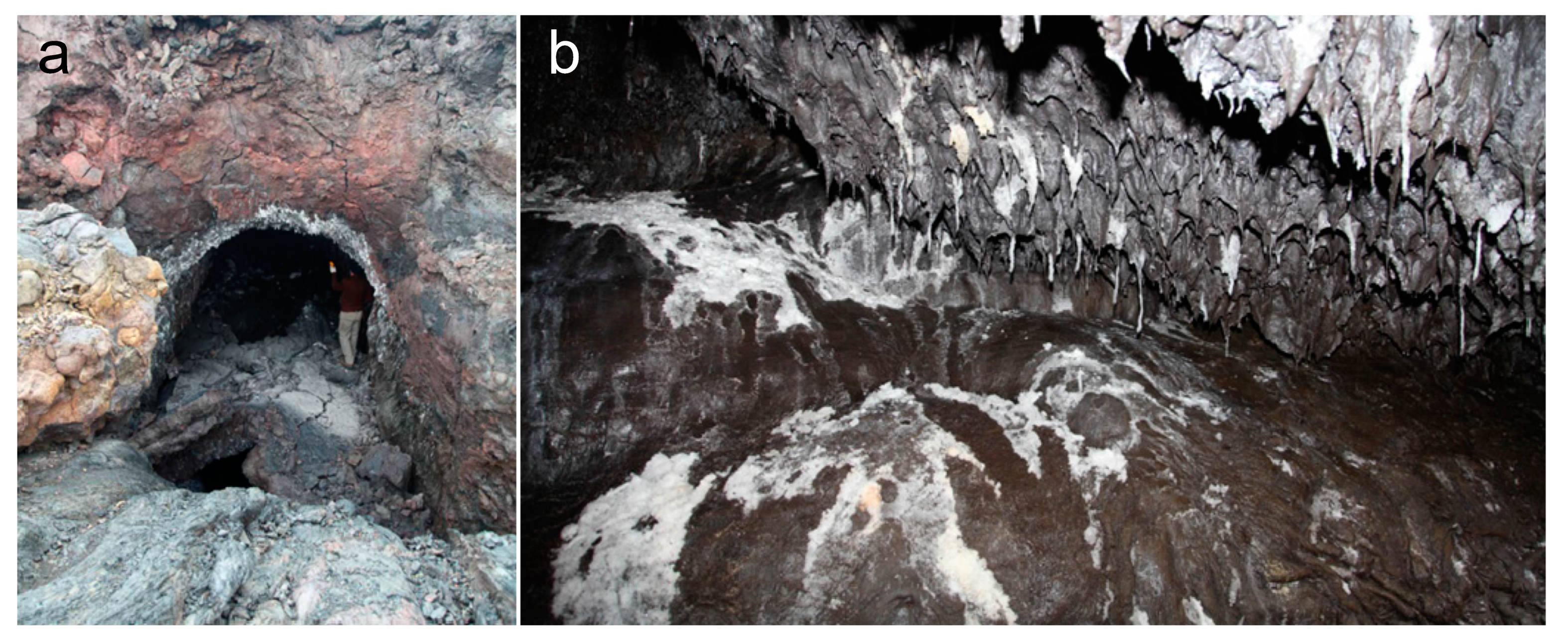
Figure 2.
Schematic diagrams of spacecraft detection on the Moon, which carry orbiting radar sounders. (a) ALSE onboard the Apollo 17 mission detecting the lunar surface (Credit: NASA/SCIENCE PHOTO LIBRARY). (b) Lunar Radar Sounder onboard SELENE mission [41].
Figure 2.
Schematic diagrams of spacecraft detection on the Moon, which carry orbiting radar sounders. (a) ALSE onboard the Apollo 17 mission detecting the lunar surface (Credit: NASA/SCIENCE PHOTO LIBRARY). (b) Lunar Radar Sounder onboard SELENE mission [41].
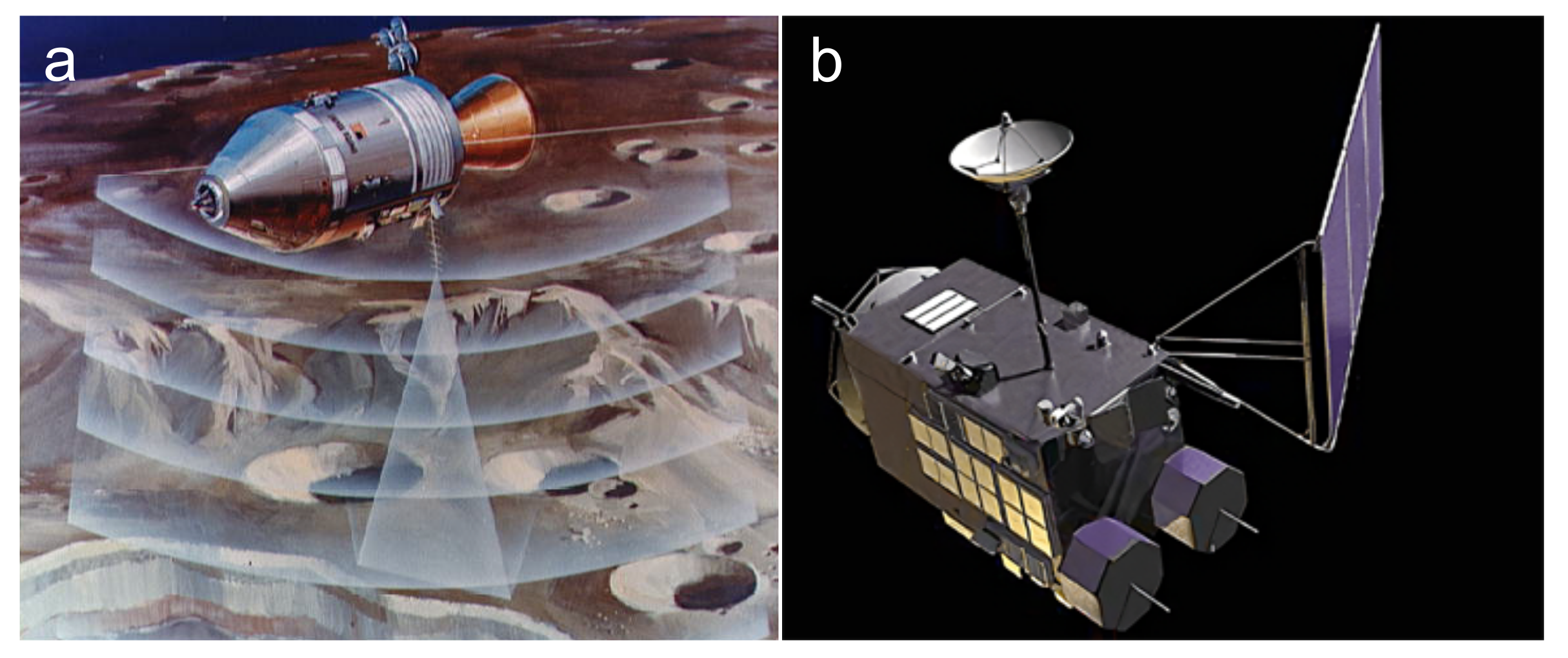
Figure 3.
(a) Schematic diagram illustrating the operating principle of ALSE [43]. (b) Schematic diagram illustrating the operating principle of LRS [44].

Figure 4.
Schematic diagram of Mars planetary orbiters, which carry the planetary orbiter radar sounders. (a) MARSIS [49]. (b) SHARAD (Credit: NASA/JPL/Corby Waste). (c) MOSIR [50].

Figure 5.
Schematic of the Moon–based GPR deployed in the Chang’e missions. (a) Yutu–1 rover of the CE–3 mission [66]. (b) Yutu–2 rover of the CE–4 mission [67]. (c) Lander of the CE–5 mission [68].
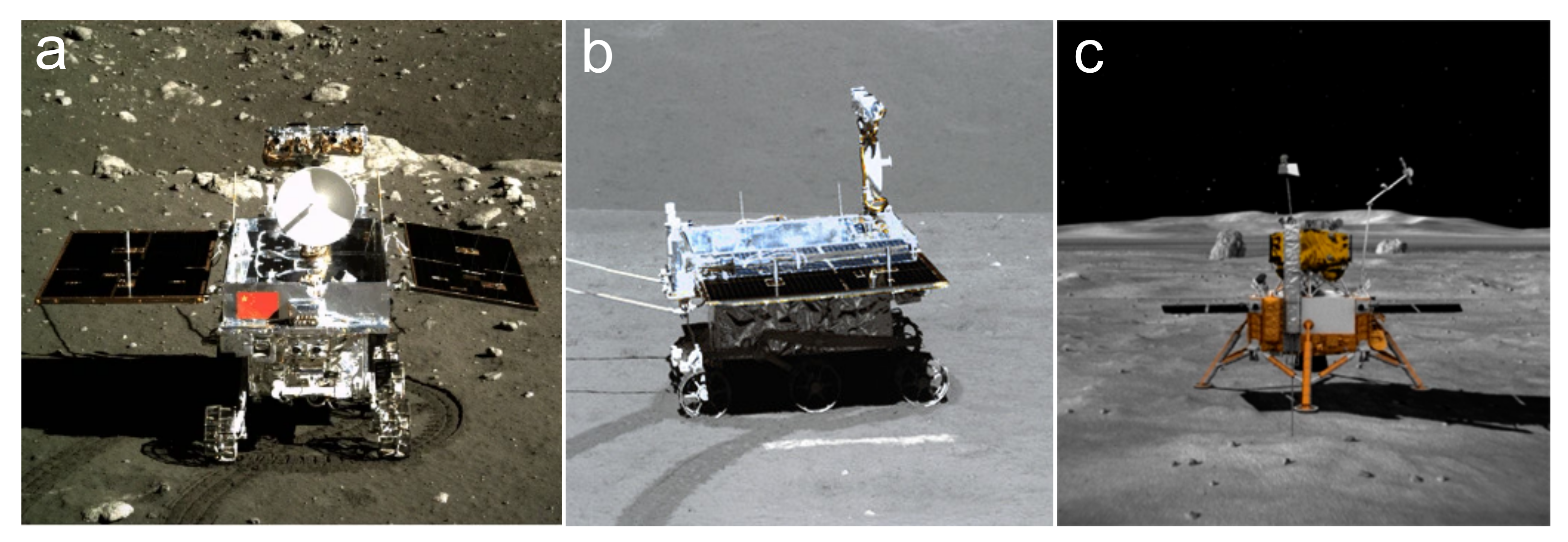
Figure 8.
The simplified lava tube model proposed by Carrer et al. [42]. The top panel illustrates how the lava tube is scanned by radar, and the bottom panel provides an example of a vertically oriented simulated radar image. Key features of the terrain correspond to features on the radar image as follows: (a) the planetary surface; (b) the apex of the lava tube; (c) the tube walls; (d) the central part of the tube base; (e) the rest of the tube base; and (f) subsurface features derived from the model.
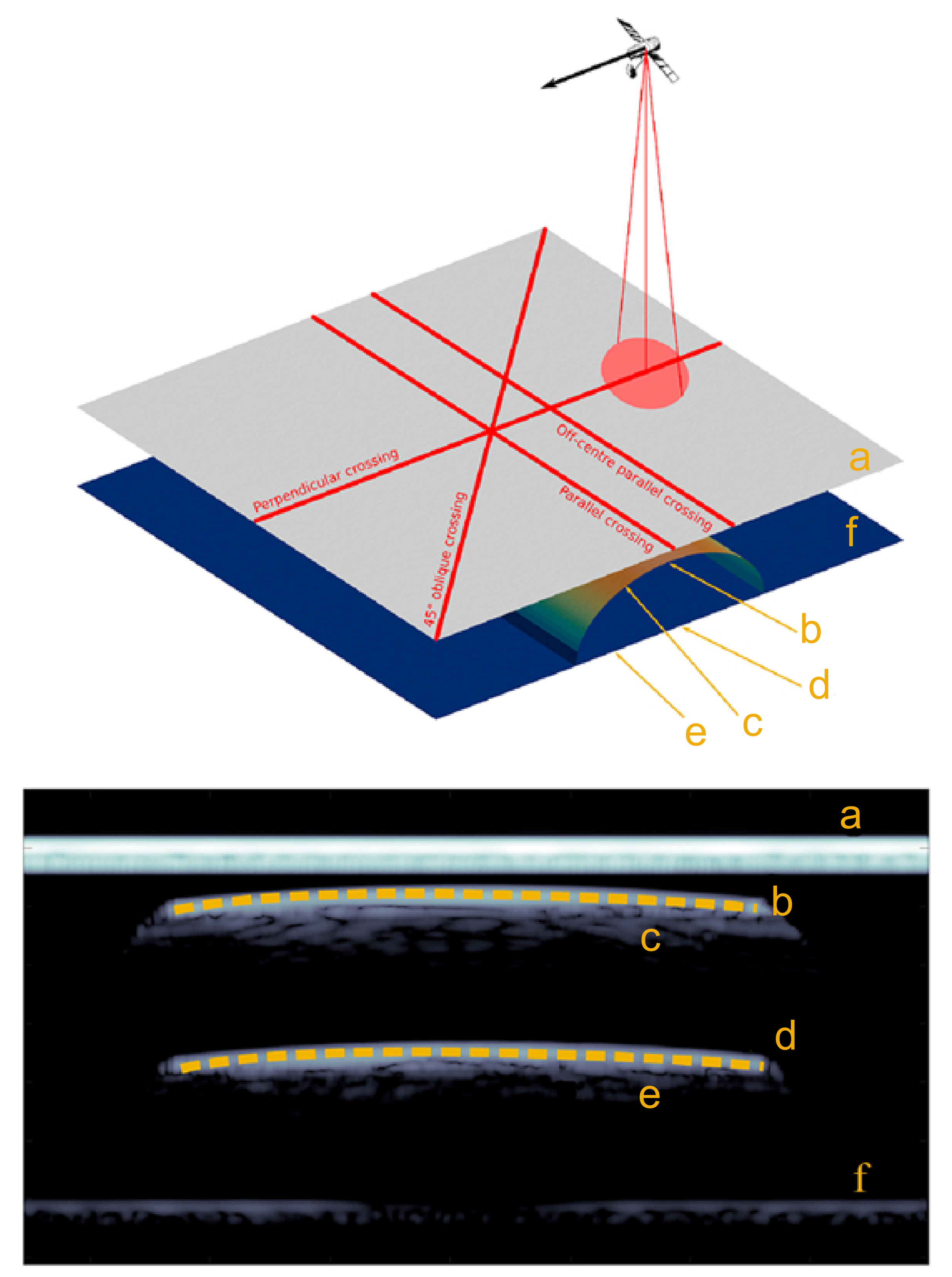
Figure 9.
The radar images obtained via different scanning methods for a lava tube [42]. (a,b) Perpendicular and diagonal scanning of the radar on the lava tube, respectively. (c,d) Radar image obtained via perpendicular and diagonal scanning, respectively. The radar image highlights the phase reversal between the reflections at the top and bottom of the lava tube. The dimensions on the horizontal axis of panels (c,d) are different in scale.
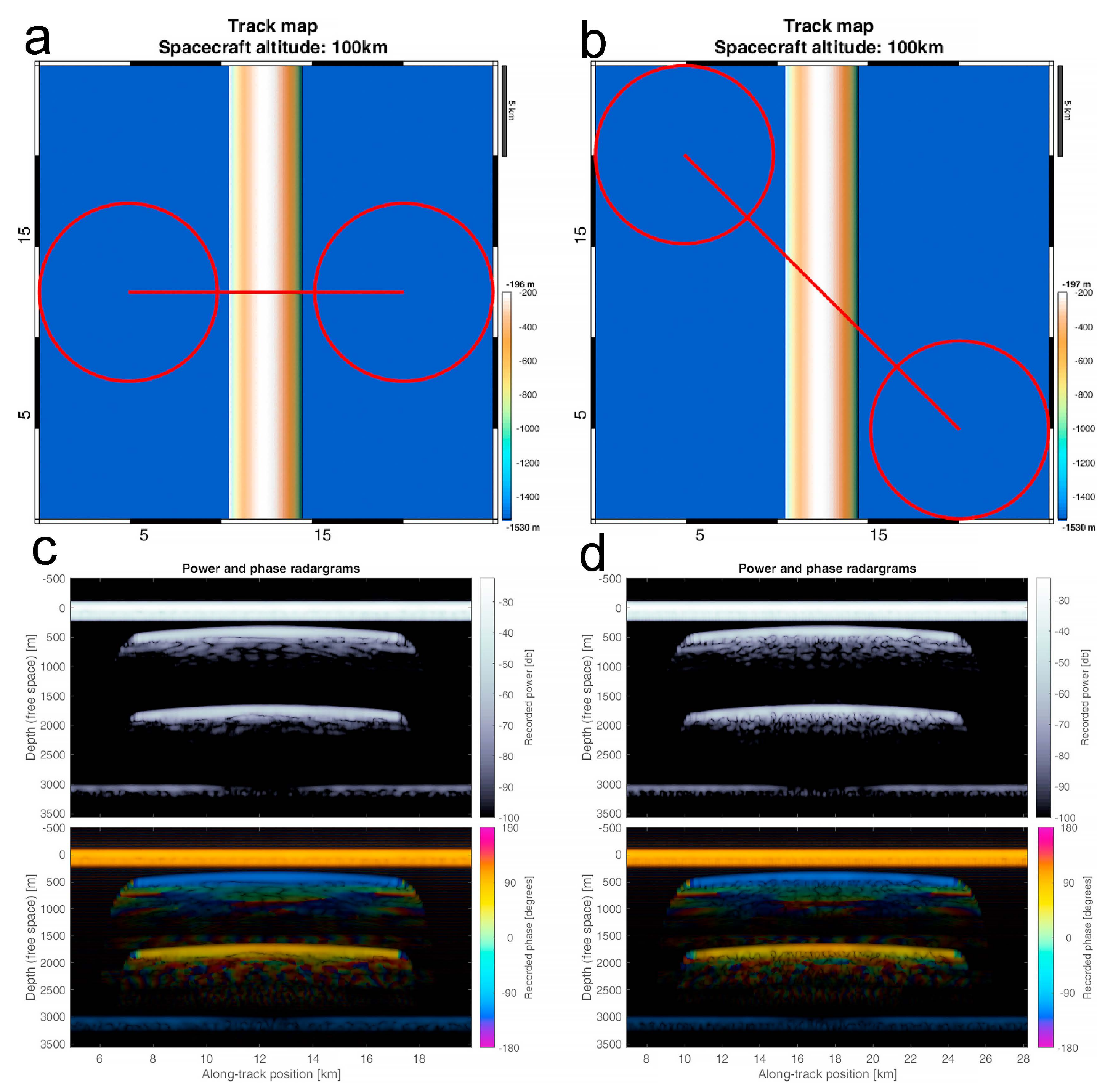
Figure 10.
The polarization change of the radar sounders electromagnetic pulse wave at the interface. (a,b) The case where the low dielectric constant enters the high dielectric constant. (c,d) The case where the high dielectric constant enters the low dielectric constant.
Figure 10.
The polarization change of the radar sounders electromagnetic pulse wave at the interface. (a,b) The case where the low dielectric constant enters the high dielectric constant. (c,d) The case where the high dielectric constant enters the low dielectric constant.
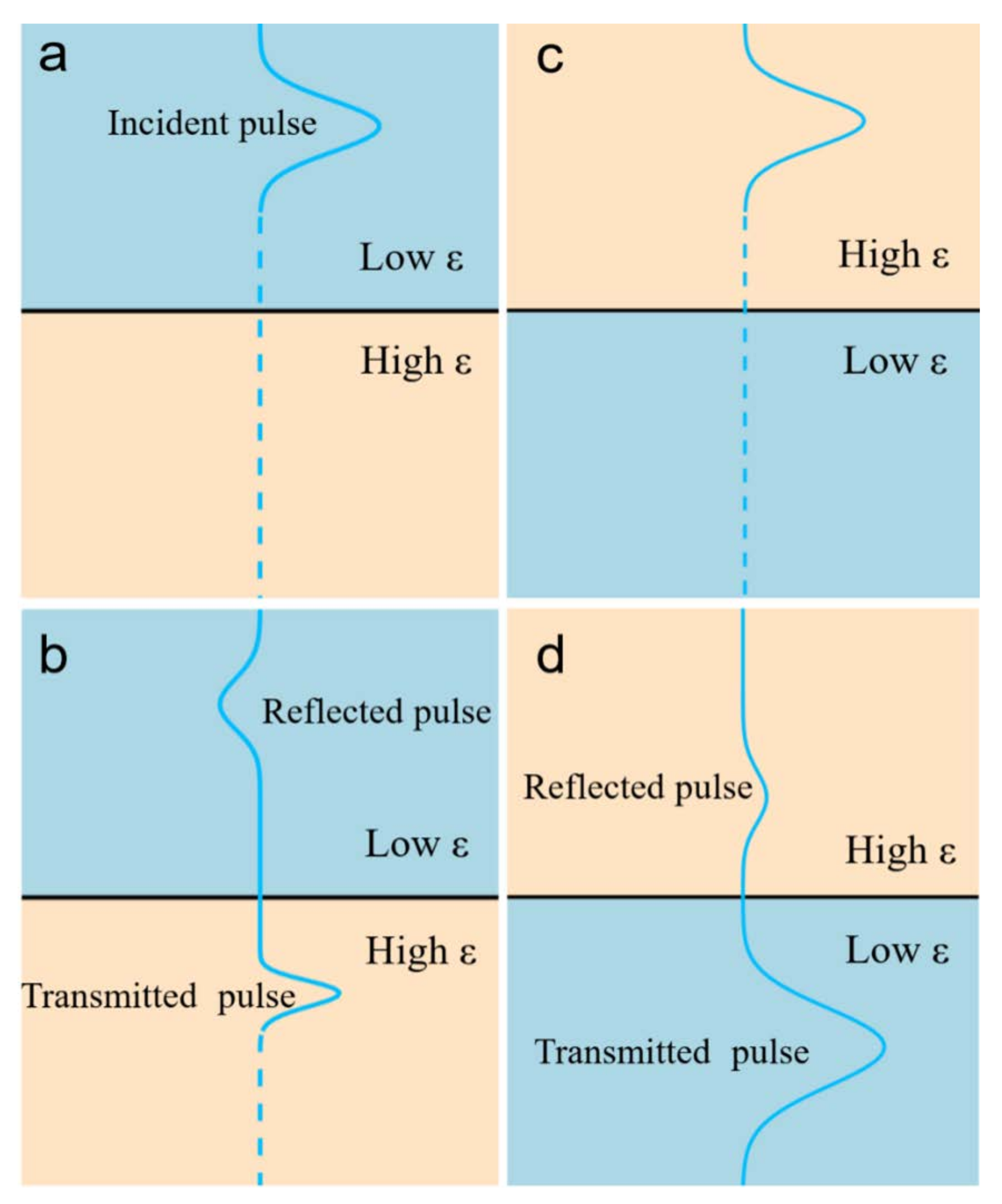
Figure 11.
The three synthetic models generated for Earth, the Moon, and Mars [18]. (a) Models used in the simulation, where the color depth represents the relative dielectric constant, with white being 0. Radar image generated from the synthetic model for a lava tube on Earth (b), Mars (c), and the Moon (d). The white arrow indicates the reflector of the bottom of the lava tube.
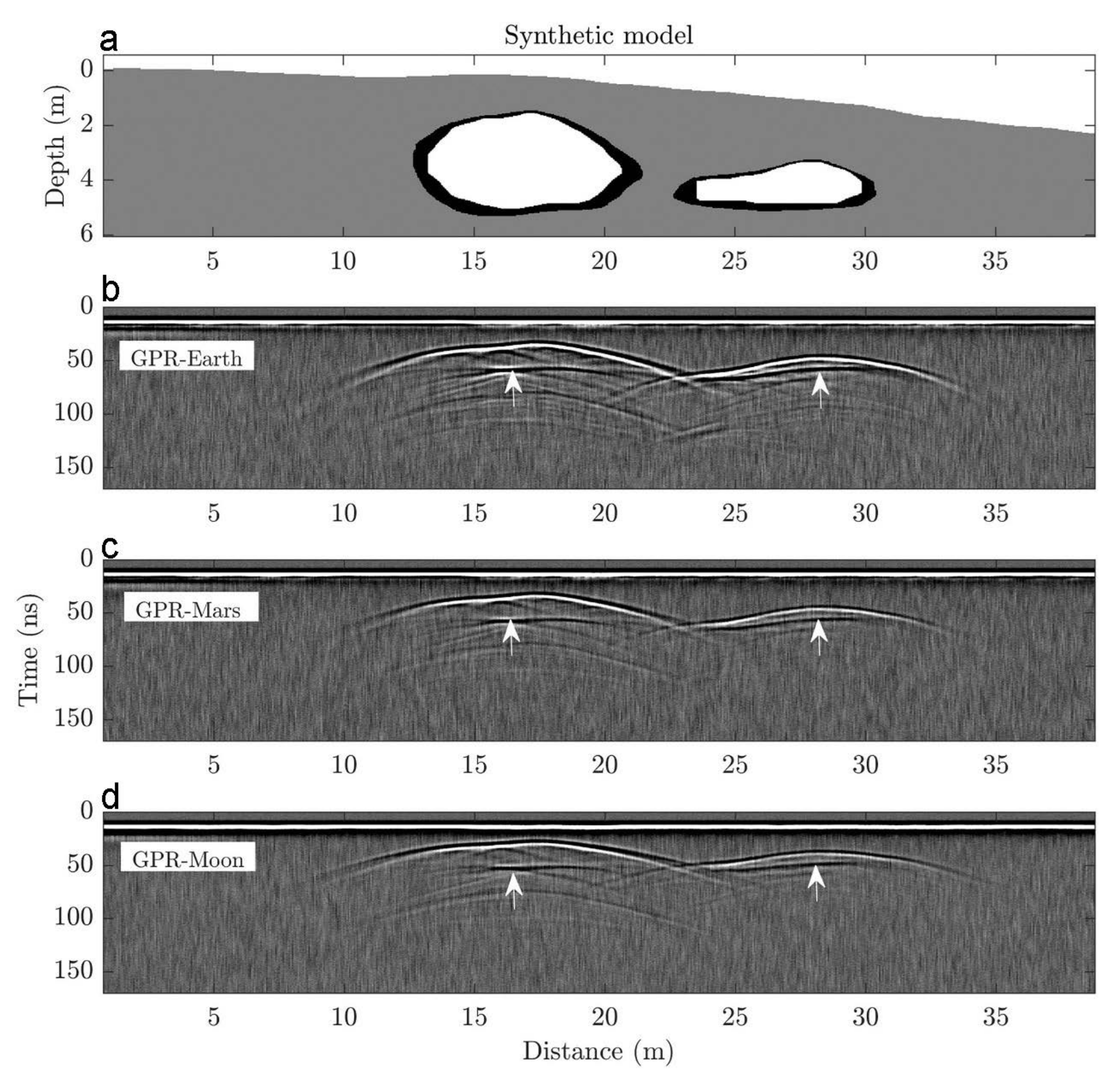
Figure 12.
Judgment flowchart lava of the tubes observed by the GPR.
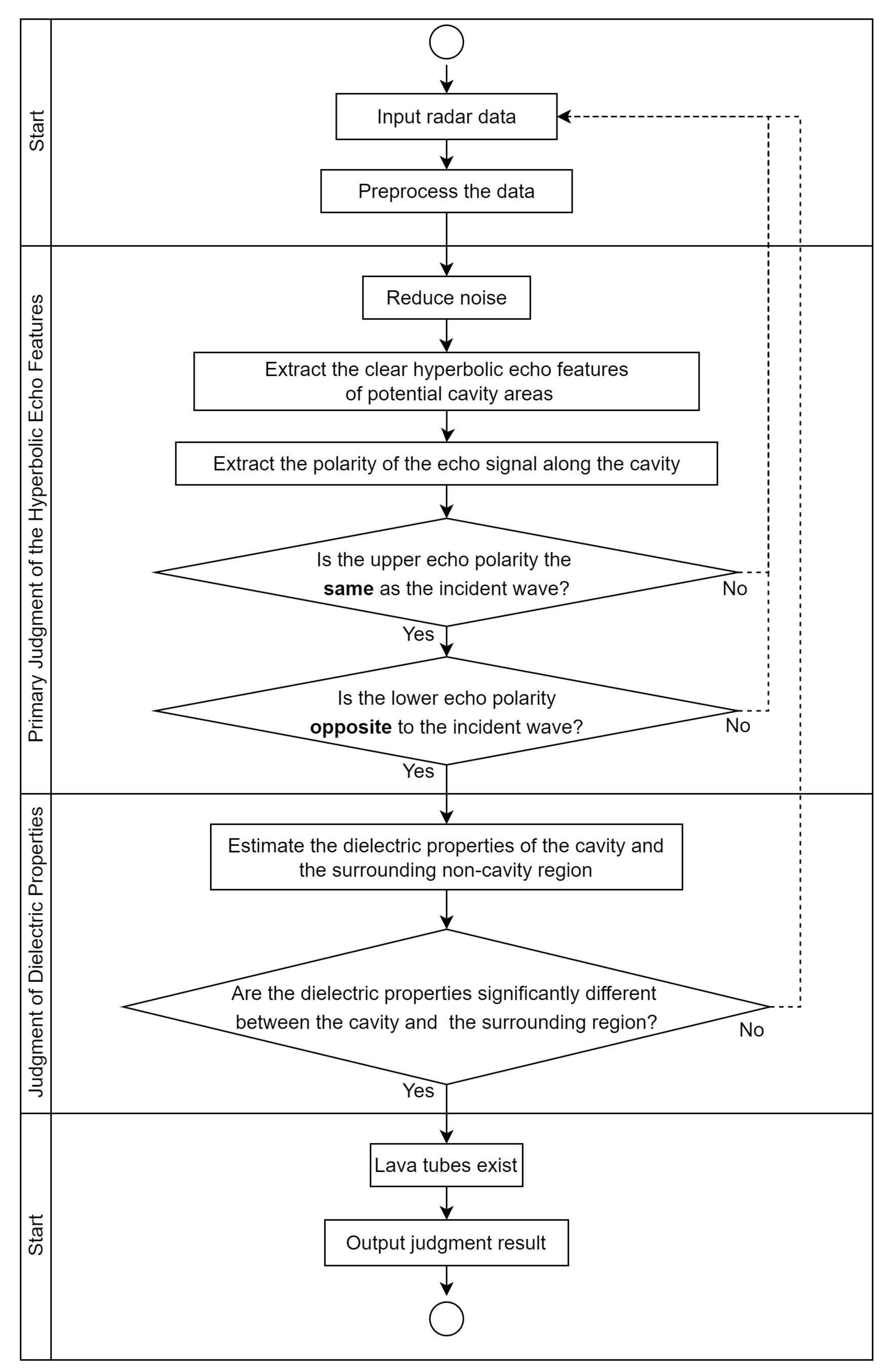
Figure 13.
(a) Location information of the lava tube in the field experiment on the ground. (b–d) Internal views of three different lava tubes, with the depth of the Skull lava tube being approximately 18 m. The white circle represents a researcher (with a height of approximately 1.8 m) used to compare the height of the lava tube [29]. (e) Radar image of the Skull lava tube [18].

Figure 14.
Potential image of a lunar lava tube skylight with a diameter of 65 m in the Marius Hills area [111]. (a) Panoramic view of the region, showing the designated area for crater counting marked by a solid white polygon. (b) Marius Hills Hole (MHH). (c–f) Magnified images of the MHH, with arrows indicating the direction of sunlight illumination (I) and camera perspective (V).
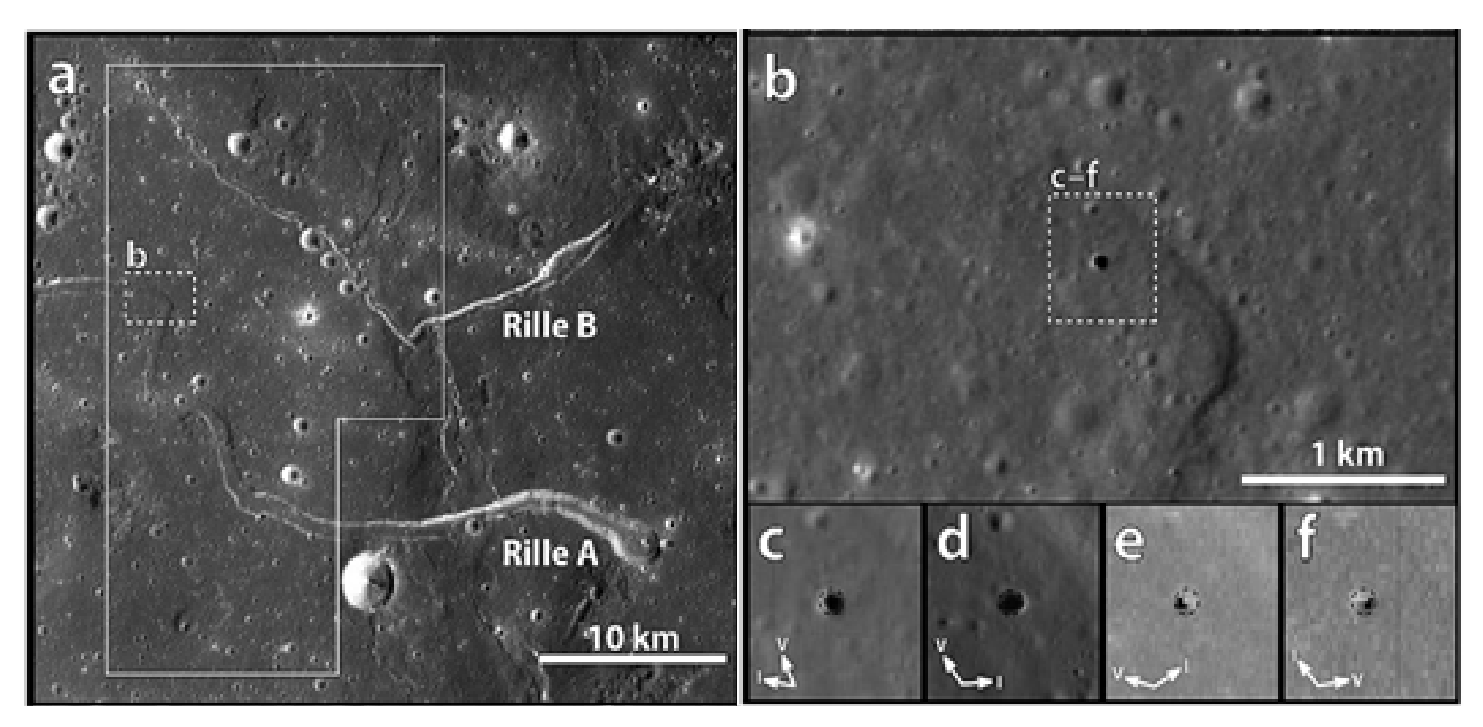
Figure 15.
Candidate sites of potential underground caverns in the Marius Hills region [19]. The color of the circles represents the power difference between the first and second echo peaks (Prb). The lower the Prb value, the greater the possibility of the existence of underground lava tubes.
Figure 15.
Candidate sites of potential underground caverns in the Marius Hills region [19]. The color of the circles represents the power difference between the first and second echo peaks (Prb). The lower the Prb value, the greater the possibility of the existence of underground lava tubes.

Figure 16.
A subsurface cavity was discovered in the area of the Ziwei crater [7].
Figure 16.
A subsurface cavity was discovered in the area of the Ziwei crater [7].

Figure 17.
The distribution of sinuous ridges in the Tharsis region of southeastern Mars (solid white lines) [116]. The white dashed lines indicate the channels connected to these winding ridges.
Figure 17.
The distribution of sinuous ridges in the Tharsis region of southeastern Mars (solid white lines) [116]. The white dashed lines indicate the channels connected to these winding ridges.
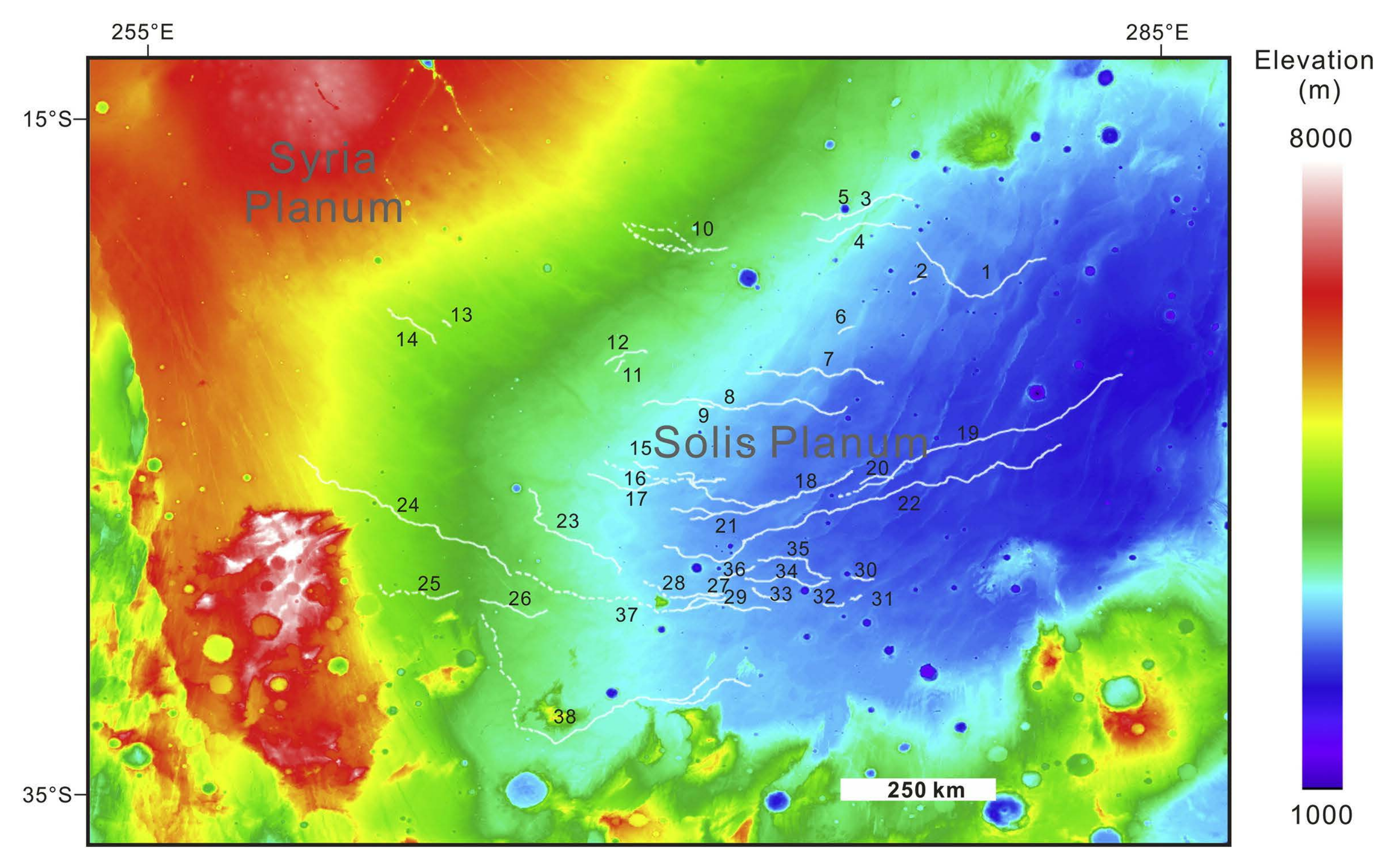
Figure 18.
Cross–sectional shapes of the sinuous ridges (a,b) and two typical cross–sectional elevation profiles (f,g) [116]. (a) Dome–shaped. (b) Double–ridged. (c) Double–ridged, with two lateral ridges (indicated by arrows) located at the top of a high, broad ridge. The area shown in the box shows the process of the double–ridged shape transitioning into a dome–shaped shape as the lateral ridges degrade. (d) Flat–crested. (e) Process of a flat–topped shape (indicated by the yellow arrow) transitioning into a dome–shaped shape (indicated by the white arrow). (f) Elevation profile along the AB line in panel (a). (g) Elevation profile along the AB line in panel (d).
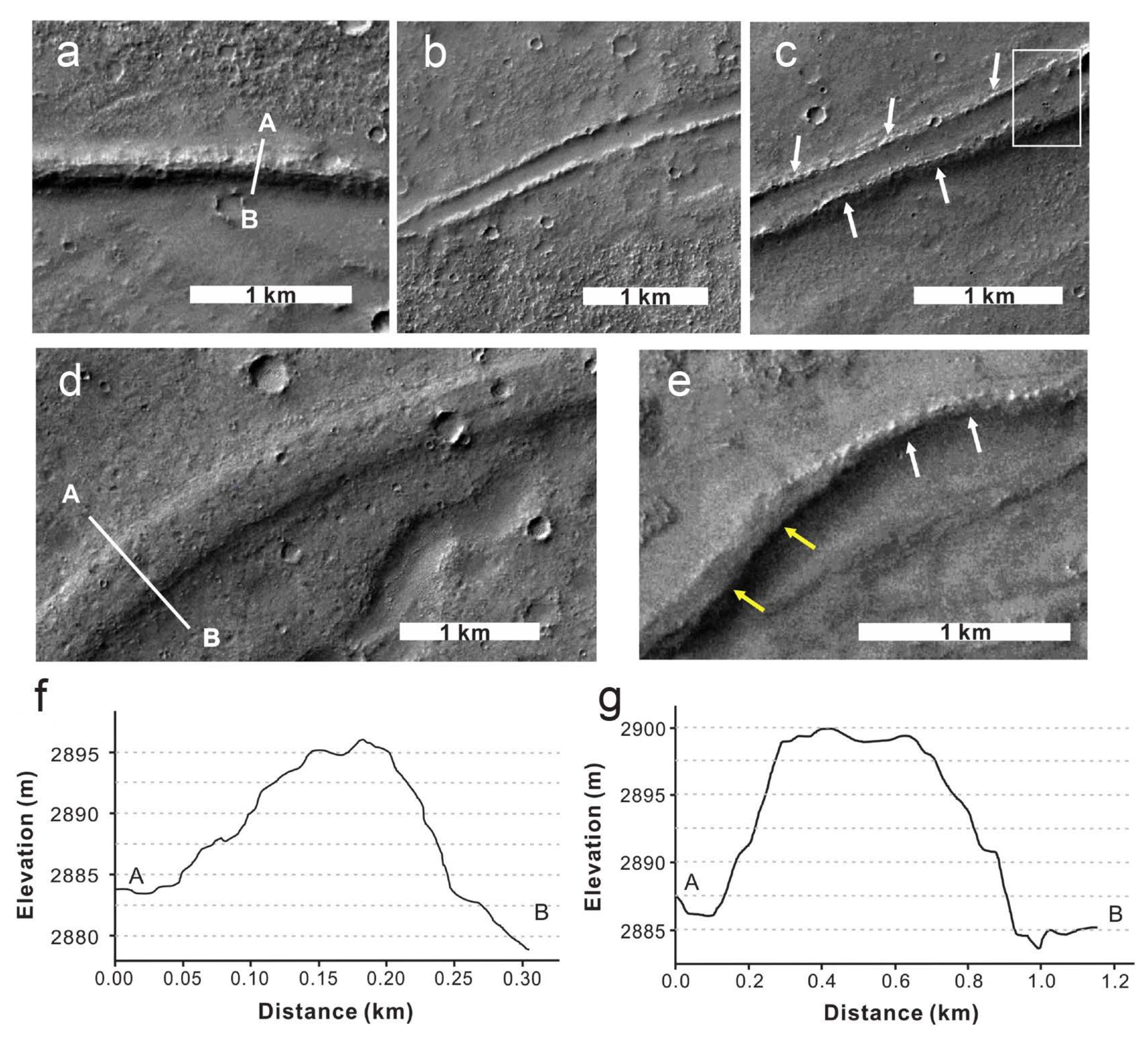
Figure 19.
Conceptual diagram of base construction in a lava tube on the Moon. (a) Diagram of astronauts exploring lunar lava tube (Source: Mars Institute/Pascal Lee). (b) Envisioning the drawing of a lava tube base (Source: Sebastian Luca).
Figure 19.
Conceptual diagram of base construction in a lava tube on the Moon. (a) Diagram of astronauts exploring lunar lava tube (Source: Mars Institute/Pascal Lee). (b) Envisioning the drawing of a lava tube base (Source: Sebastian Luca).
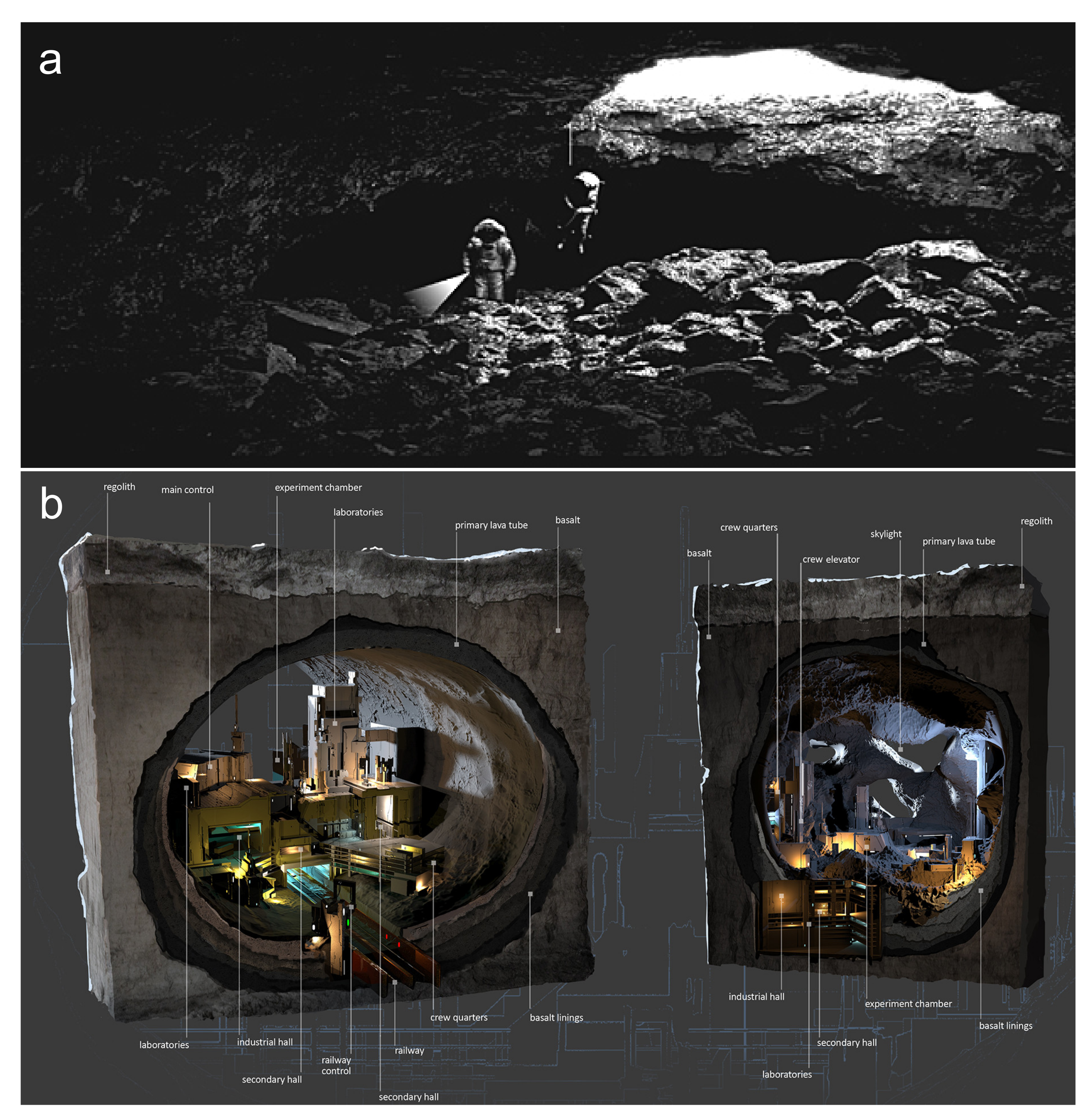

| Radar | ALSE | LRS | ||
|---|---|---|---|---|
| Orbiter | Apollo 17 | SELENE | ||
| Launch year | 1972 | 2007 | ||
| Status | HF1 | HF2 | VHF | – |
| Wavelength (m) | 60 | 20 | 2 | 60 |
| Center frequency (MHz) | 5.266 | 15.8 | 158 | 5 |
| Detection depth (m) | 1300 | 800 | 160 | 5000 |
| Vertical resolution (m) | 300 | 100 | 10 | 75 |
| Power (w) | 130 | 118 | 95 | 800 |
Channel 1 of high frequency. Channel 2 of high frequency. Very high frequency. LRS is available in 1 MHz and 15 MHz optional.
| Radar | MARSIS | SHARAD | MOSIR |
|---|---|---|---|
| Orbiter | Mars Express | Mars Reconnaissance | Tianwen–1 |
| Launch year | 2005 | 2006 | 2020 |
| Orbital altitude (km) | 250–900 | 250–300 | 265 |
| Center frequency (MHz) | 1.3–5.5 | 15–25 | LF: 10–20 HF: 30–50 |
| Detection depth (km) | 0.5–5 | 0.1–1 | 0.1–1 |
| Vertical resolution (m) | 150 | 15 | 30(LF)/7.5(HF) |
| Power (W) | 10 | 10 | ≥100 |
| Mission | CE–3/4 | CE–5 | CE–7 | ||
|---|---|---|---|---|---|
| Launch year | 2013/2018 | 2020 | 2026 (est.) | ||
| Status | LF | HF | – | LF | HF |
| Center frequency (MHz) | 60 | 500 | 2000 | 60 | 800 |
| Detection depth (m) | ≥100 | ≤30 | ≥2 | ≥400 | ≥40 |
| Thickness resolution (m) | Meter–sized | 0.3 | Centimeter–sized | 2 | 0.15 |
The parameters of the CE–7 lunar radar are from the China Lunar Exploration and Space Engineering Center (CLEP) bidding requirements.
| Radar | RIMFAX | RoPeR | WISDOM | ||
|---|---|---|---|---|---|
| Rover | Perseverance | Zhurong | ExoMars | ||
| Launch Year | 2020 | 2020 | 2028 (est.) | ||
| Status | LF | HF | LF | HF | – |
| Center frequency (MHz) | 375 | 675 | 55 | 1300 | 1750 |
| Detection depth (m) | ≥10 | ≥10 | ≥3 | 3–10 | |
| Thickness resolution (cm) | 10–20 | 20–40 | Meter–sized | Centimeter–sized | 3 |
| Location | Coordinates | Data Source and Analysis Method | Reference |
|---|---|---|---|
| Marius | 14.2°N, 56.7°W | SELENE Image detection | Haruyama et al. [111] |
| Marius | 13.00–15.00°N, 55.99–58.15°W | SELENE Radar detection | Kaku et al. [19] |
| Mare Imbrium | 44.1214°N, 19.5116°W (CE–3 landing site) | Yutu rover Radar detection | Ding et al. [7] |
| Marius | 13.096°N, 57.056°W | Kaguya, LRO LOLA Image detection | Sauro et al. [8] |
| Gruithuisen | 34.618°N, 43.467°W | ||
| Hyginus Rill Tectonic | 8.384°N, 5.630°E |
| Location | Coordinates | Data Source and Analysis Method | Reference |
|---|---|---|---|
| Solis Planum | 15–35°S, 260–285°E | CTX, HiRISE Image detection | Zhao et al. [116] |
| Echus Chasma | 1.0°N, 278.0°E | SHARAD Radar detection | Mansilla et al. [117] |
| Arsia North | 3.062°S, 123.930°W | CTX, HiRISE Image detection | Sauro et al. [8] |
| Arsia South | 14.377°S, 119.949°W | CTX stereo–pairs, HiRISE Image detection | |
| Olympus | 19.456°N, 133.399°W | CTX stereo–pairs Image detection |
Disclaimer/Publisher’s Note: The statements, opinions and data contained in all publications are solely those of the individual author(s) and contributor(s) and not of MDPI and/or the editor(s). MDPI and/or the editor(s) disclaim responsibility for any injury to people or property resulting from any ideas, methods, instructions or products referred to in the content. |
© 2023 by the authors. Licensee MDPI, Basel, Switzerland. This article is an open access article distributed under the terms and conditions of the Creative Commons Attribution (CC BY) license (https://creativecommons.org/licenses/by/4.0/).
Share and Cite
MDPI and ACS Style
Qiu, X.; Ding, C. Radar Observation of the Lava Tubes on the Moon and Mars. Remote Sens. 2023, 15, 2850. https://doi.org/10.3390/rs15112850
AMA Style
Qiu X, Ding C. Radar Observation of the Lava Tubes on the Moon and Mars. Remote Sensing. 2023; 15(11):2850. https://doi.org/10.3390/rs15112850
Chicago/Turabian StyleQiu, Xiaohang, and Chunyu Ding. 2023. "Radar Observation of the Lava Tubes on the Moon and Mars" Remote Sensing 15, no. 11: 2850. https://doi.org/10.3390/rs15112850
Note that from the first issue of 2016, this journal uses article numbers instead of page numbers. See further details here.